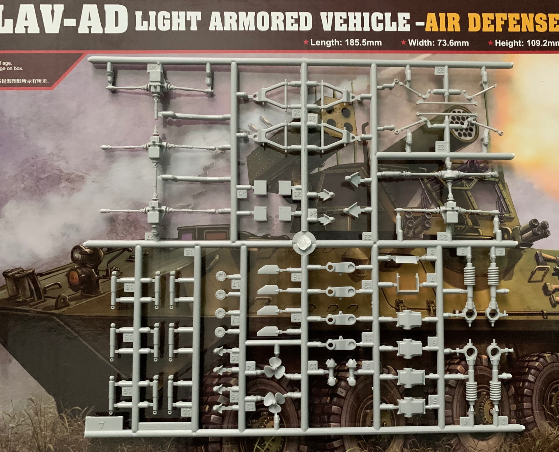
I have Def Wheels so the only parts missing are 2x A19 and 1x A18 struts.
The current need is the R knowledge. I have the Eduard PE set, looks like plumbing on the bottom hull for the outriggers. Anything else I might be missing?
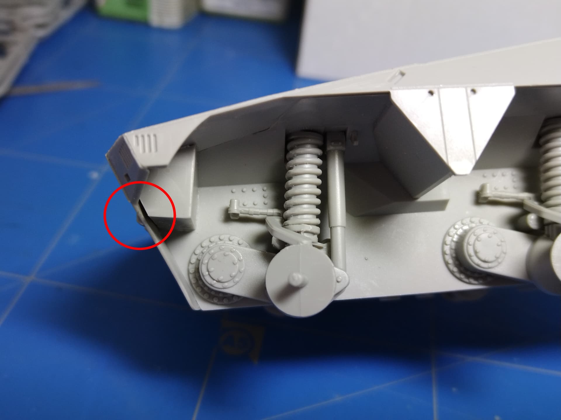
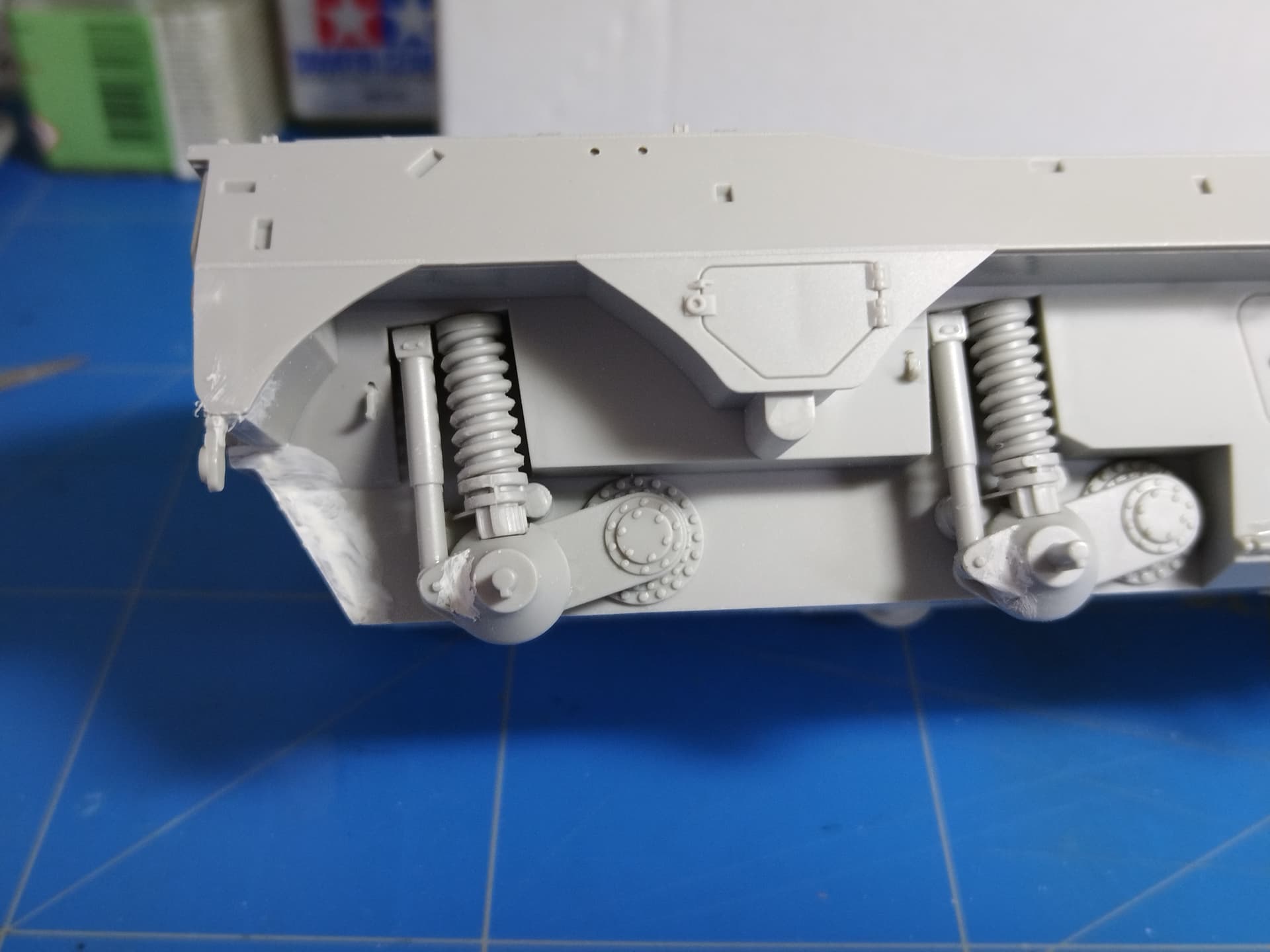
Here are some progress and some more issues. As I always do I assembled the hull prior to adding any details. The seams are far from perfect and putty was mandatory. Not a big deal but it’s time consuming. Wht I’m more worried about is the large gap under the headlight compartment. The gap is present on both sides no matter how I tried to press the front panel. Styrene will come to the rescue.
The front wheels are steered and glued in their final position.
That’s always the issue isn’t it. A small insignificant gap like can add hours onto a simple part of the build. It is annoying they still get things like this wrong.
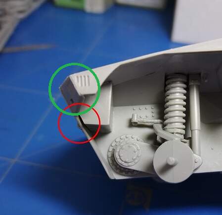
Hi Olivier. The fit on yours is very different to mine. I think your issue is the front plate has been glued in slightly forward, possibly because the hull top may be a tad out of alignment with the bottom - hence your gaps.
Your plate seems to be attached to the front of the side sections with the front having a noticeable seam, where the join should be on the bevel on the corner.
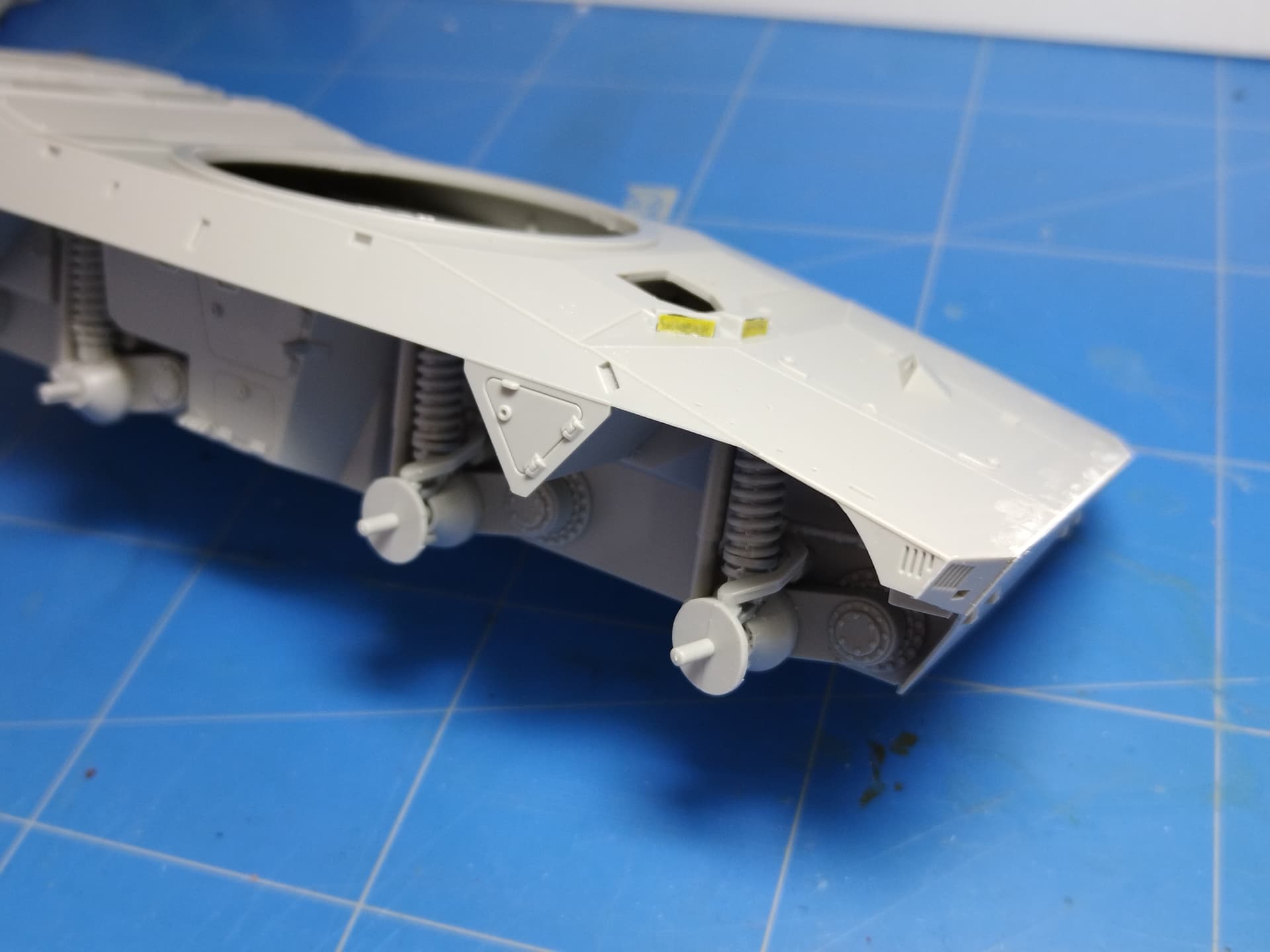
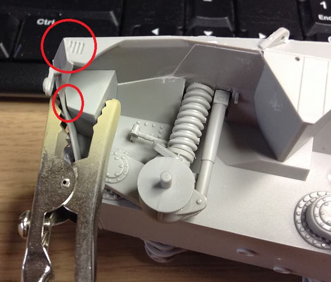
This means the top of the front plate is too far from the hull. I needed to clean off flash there. If you glue the front between the side sections, and have the bevel the front panel is closer to the hull. This is how mine looks:
I have a much smaller gap on the headlight housing (I have left mine off and will attach after painting in case the headlight can be seen through the holes)
I glued the front plate to the hull first and the only the top of the hull.
The front plate to the hull attachment looked OK with no misalignment. Obviously it was not.
I guess your option of not gluing the headlight housing is the best. Too late for me.
My kit has quite a lot of flash in places and there was a fair bit of movement for placement of the upper hull. I’m thinking that in cleaning up the flash, and checking the alignment so many times, it also helped the alignment of parts. It was more luck than good judgement. Good luck with the rest of the build.
I suppose the crane being working leads onto ----- will you have it up, with a load under slung and the support legs down … or crane stowed and supports up ? did you say there was an issue with the supports ? I forget ??
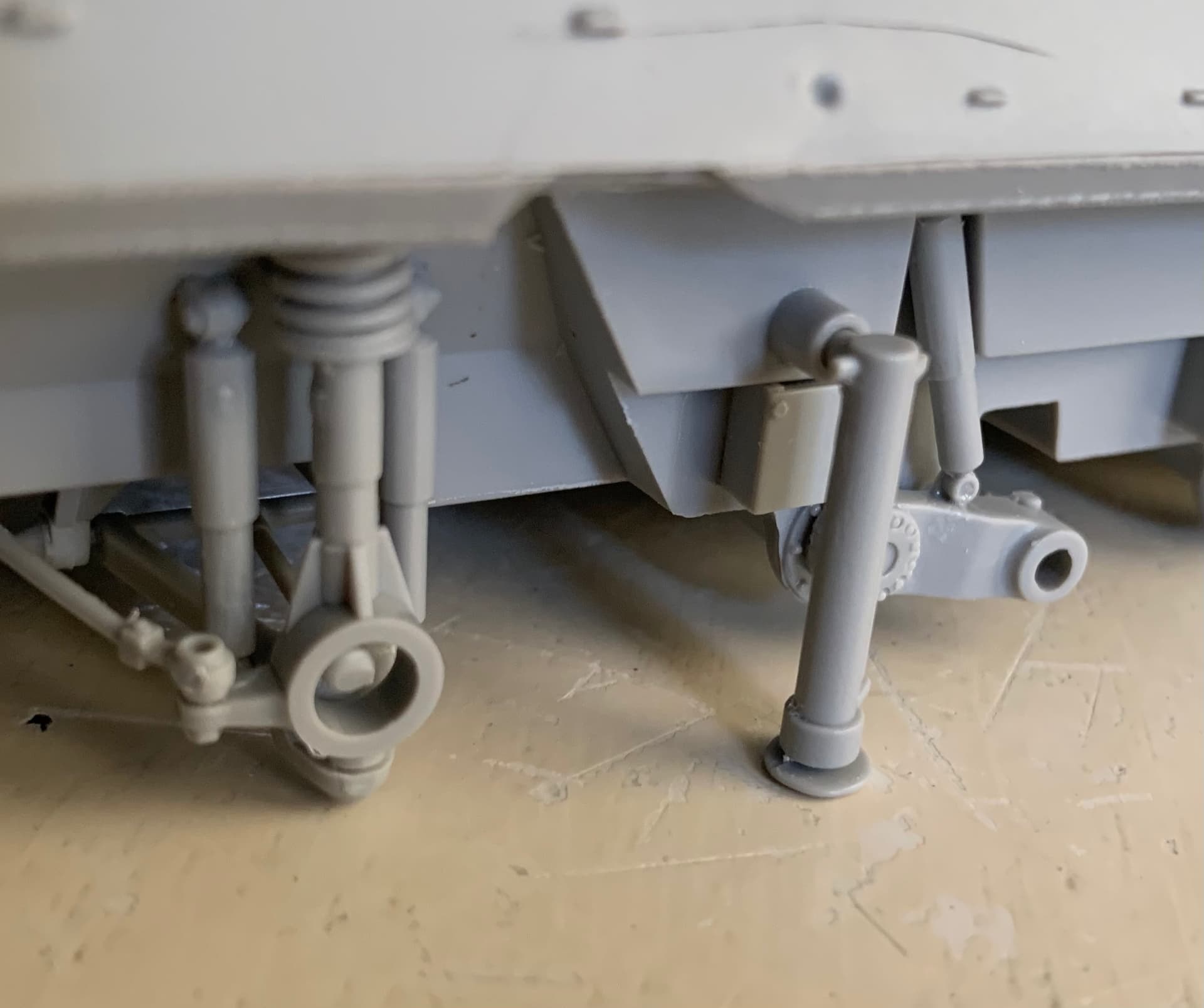
The issues with the outriggers is they are molded for travel and not for under load. I assume if using the crane the out riggers should be deployed but that might be dependent on load and angle of crane. Also need to add the hoses for the outriggers.
That’s why I have held off that next step. Built most of the kit in the living room watching TV. Now, I have to build in the hobby room for the rest. Might start my LAV-AD kit next to get to the same point.
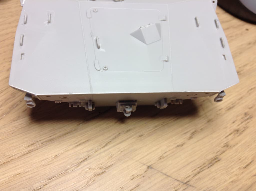
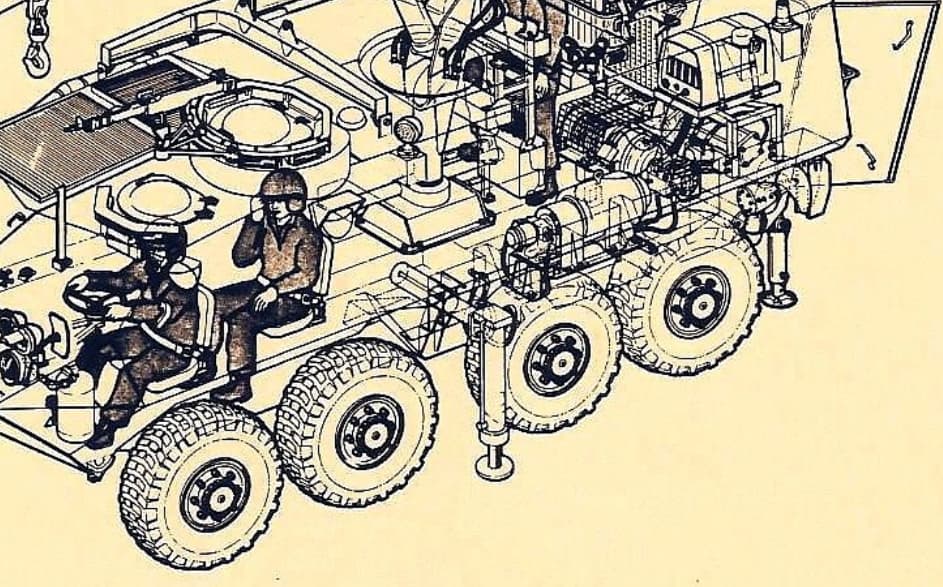
I am not sure if the outriggers on the LAV go out and how far if they did but I would use a rod to extent the pad to the ground. That is just for the hull outriggers. I am not sure where the other outriggers hanging on the rear would go. Looks like the jacks are stored on the front left on the hull.
I can find photos of the crane “deployed” not under a load but not the outriggers. @white4doc, doc you got a photo or can you describe if you have seen one with deployed outriggers?
Doing the geometry stuff:
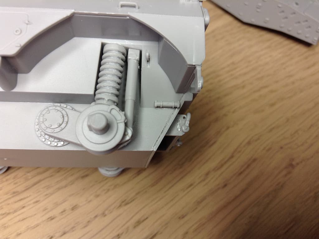
The outrigger is stored for travel with the foot plate pushing against the notch in the hull.
It needs to swing down to rest against the ground.
Can it swing down and pass the wheel in front of the outrigger.
Does it need to be pulled out to bypass the wheel?
The spades on sticks are to keep the vehicle from sliding backwards when winching.
Don’t know where they attach to the vehicle though. One possible option could be that
they attach to the winch frame but the two images I have found that show the winch don’t show any obvious attachment points.
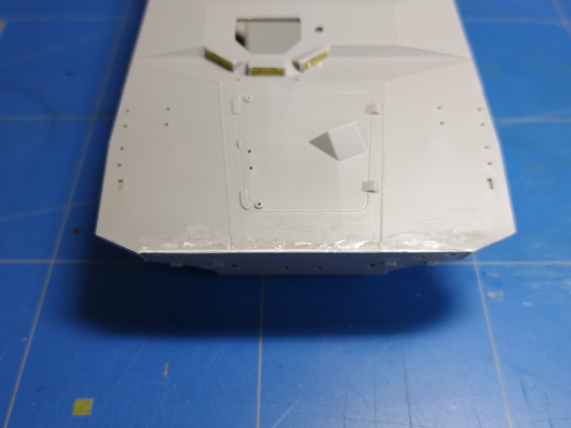
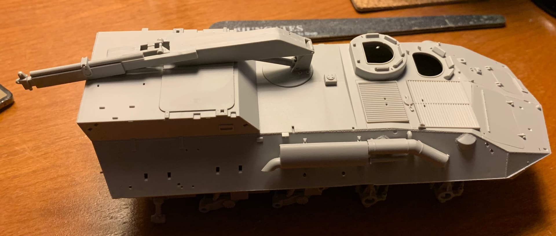
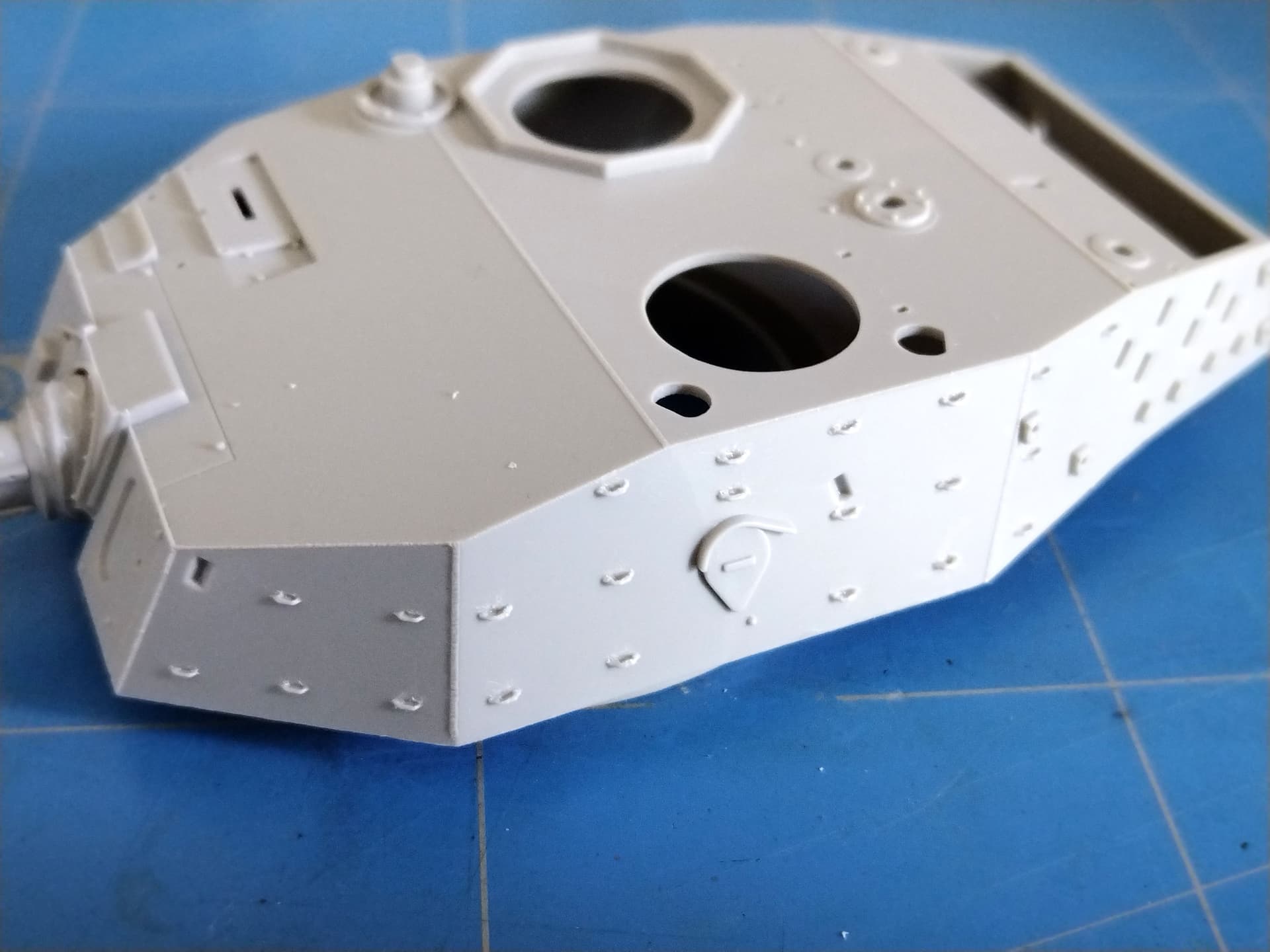
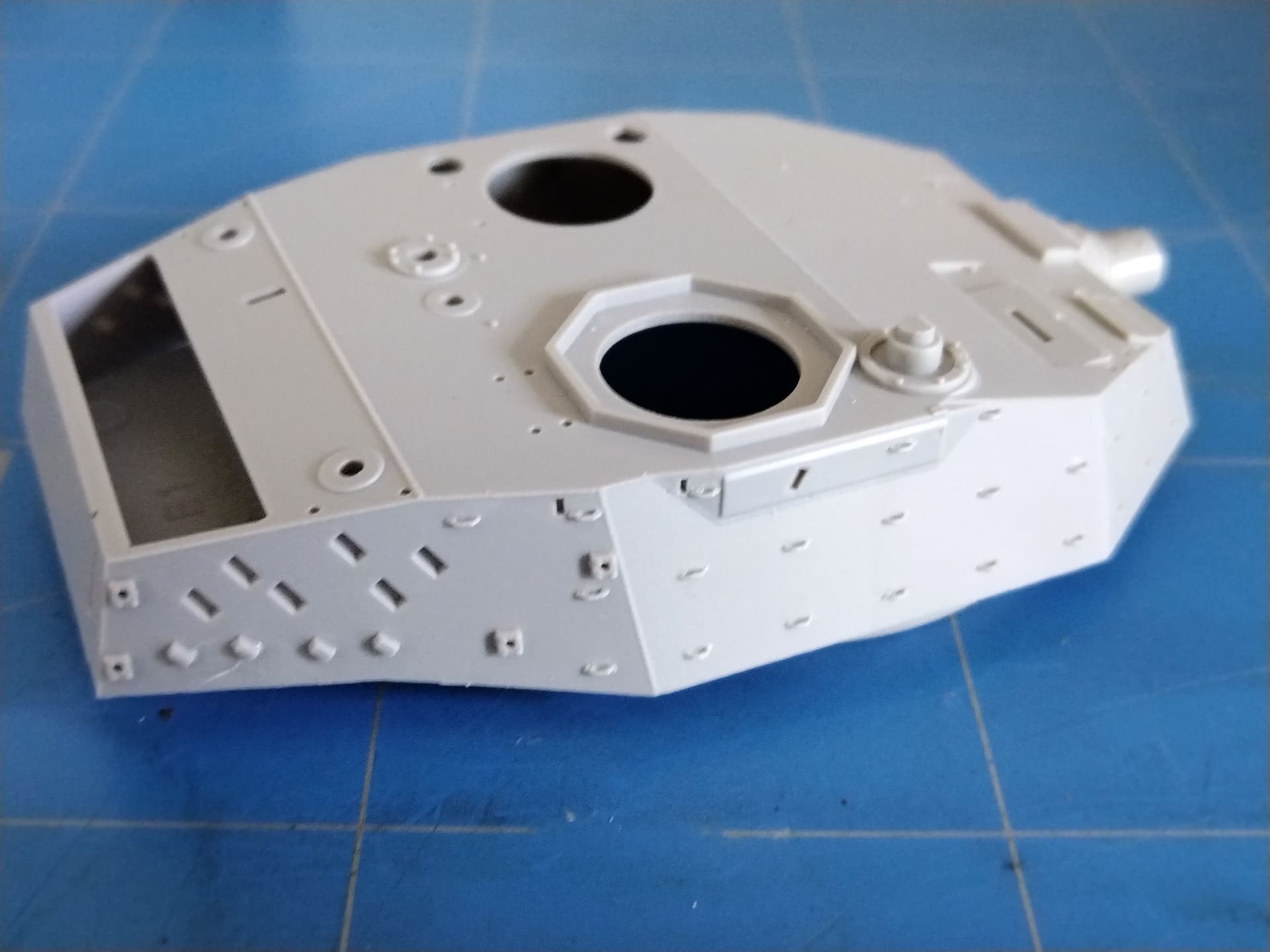
I managed to get some free time to make a little progress on the Rooikat. The turret shell is assembled and I tackled the tie-downs. As usual those are solid molded. Considering their number and how well they are aligned I didn’t try to replace them. Instead I used a sharp blade to carve them so I create the illusion of welded tie-downs. I’m quite satisfied with the result. A pin-wash when time comes will achieve the illusion I guess.