BLOG: Kitty Hawk 1/35 SH-60B Seahawk

Again, input from my readers caused me more work. It was one of those two-steps back and one forward.

I tried to save the damaged door window, but it was a mess. The other two door windows in the kit were for other version of the Sikorsky bird inlcuding the Blackhawk and their cockpit door windows varied slightly in configuration. I woke up thinking about this and decided to go for it. The model’s coming out too good to let that crappy window detract from it.

I filed and sanded the replacement and got it to fit reasonably well.

I installed it without mess up, repainted the door’s interior and did some trim painting around the outside. This took quite a while.

I then repainted the landing gear shock strut to do it like it’s supposed to be. Still needs just bit of tending loving care.

Here’s the fixed door and the towed sonar rear portion freehand. No decals for that. I had to blend Tamiya yellow and white to get to the lighter yellow.

And I’m repainting the sonobuoy bays. The inside is tan, and the holes are completely black as I could see looking more closely to some photos. I didn’t finish this job today. I got the tan done and most of the black. I will have to back paint the body color next session.

The main struts need some brake lines. I should add them since I added all those tubes on the rotor head.

Till next time…

8 Likes

A reader on one of the other forums piloted the Seahawk and has continued to provide me with invaluable prototype information about the real bird and I’ve incorporated everything he’s told me. Yesterday he told be about the real colors of the antenna and the sonobuoy dispenser. And he showed me the brake lines on the main gear.

I put in the brake lines. I used magnet wire and diameters of Albion tubing to make a faux fitting. I made a strap clamp out of wine bottle foil. This stuff works great, but you first must remove any printing or coating on it with acetone. The coating prevents good gluing.

I realize that is not the kind of clamp they actually use, but the kind they use is really hard to model.

i then finished all the painting on the sonobuoy rack and it looks much better. I also painted the break line leaving the brass natural metal since the actual junction is natural metal also.

Lastly, I stripped the decal off the airbrake on the MAD (magnetic anolmaly detector) which I have been erroneaously calling a towed sonar device, and painted it flat white to simulate the styrofoam that they are now made of. I will paint the aluminum pad that holds it on tomorrow.

That brings us up to date. I need details of the engine bay cover latch. I’m going to mount both the bay door and the cockpit door with bent wires. We’re getting closer to the end each day. I still have the running lights to install, do the powder weathering, and then mount the blades and the tail boom. I have to paint and install the main rotor folding in clamps. And it will be done.

Meanwhile, if y’all are interested in ship stuff, I’ve started another thread on this site in the building of the missing interior for the new Takom 1:72 USS Missouri 16" main turret. The model’s cool, but has nothing but the exterior shell. I’m drawing and will 3D print all of the interior apparatus down to the first projectile deck. I’ve finished the main guns yesterday, and starting working on the below turret decks.

Here’s the guns…

Here’s the link to the thread.

Bis Morgan… (see you tomorrow.)

7 Likes

My Seahawk pilot has given me more suggestions including how each blade (main and tail) are color coded and used in managing the main rotor folding process. The blade clamps are also color coded to their respective blades. The colors are also on the main rotor hub. I’m going to color some tiny strips of Tamiya tap and add this micro-details. The scheme is Forward starboard blade is Blue , Aft Starboard blade is Red , Forward Port Blade is Yellow and Aft Port Blade is black .

I finished all the weathering I’m going to do. I dirtied the bottom up and added dirt on the walking arees on the roof. I got the engine door installed, broke it off in handling the model improperly and glued it back on again. I got the front door mounted with wire. And I spent WAYYYYY to much time screwing around with the tiny marker lights on the wheel sponsons and the windshield wipers. Didn’t finish them, but will do so today.

Here’s the bottom: Notice the wheels are now on.

And here’s the model showing its newly attached doors. I’m very happy I was able to fix that door window. Dodged a bullet on that one.

Lastly, the wipers. I find that some of the smallest details drive me the most crazy. It’s the Pareto principle at work, except it’s 3% of the parts take 90% of the work (and aggravation). It’s a small gluing area and they weren’t drying correctly. I ended up using gel CA. I’m wiring them on since the mount points weren’t holes, just tiny flat spots. I want the model to be able to put for the long haul.

When laying the model on its side while putting on the cockpit door I broke off the port side mirror. Glued it on with gel CA and then broke it off again. This time I’m going to J-B Weld it and then not touch it again.

6 Likes

Will you be blogging the turret exclusively over at FSM rather than here ? Those guns look great !

It’s looking great. I can’t wait to see it completed w/the folded rotors.

Find the turret build right here… Takom Iowa Class Mark 7, 16"50Cal Turret with Full Interior Start-to-Finish - #19 by Builder2010

In the middle of an ice/sleet/rain/snow storm today and into tomorrow. Good day to spend some time in the basement building cool things.

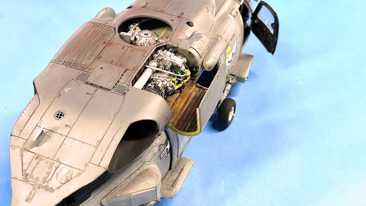
It was pointed out to me that I mounted the engine hatch at the wrong angle, but couldn’t get the work platfom part flat. Well… after carefully looking at a guy kneeling on the hatch and working on the engine, I realized that I put the wear strips on the wrong wing of the hatch. The strips go to the hinge side, not the outside. With that understanding, I removed the strips, fixed the paint, made new strips, applied them and redid the weathering. I also had to repair where I had glued the door in the wrong position to the helicopeter’s body. All’s well that ends well.

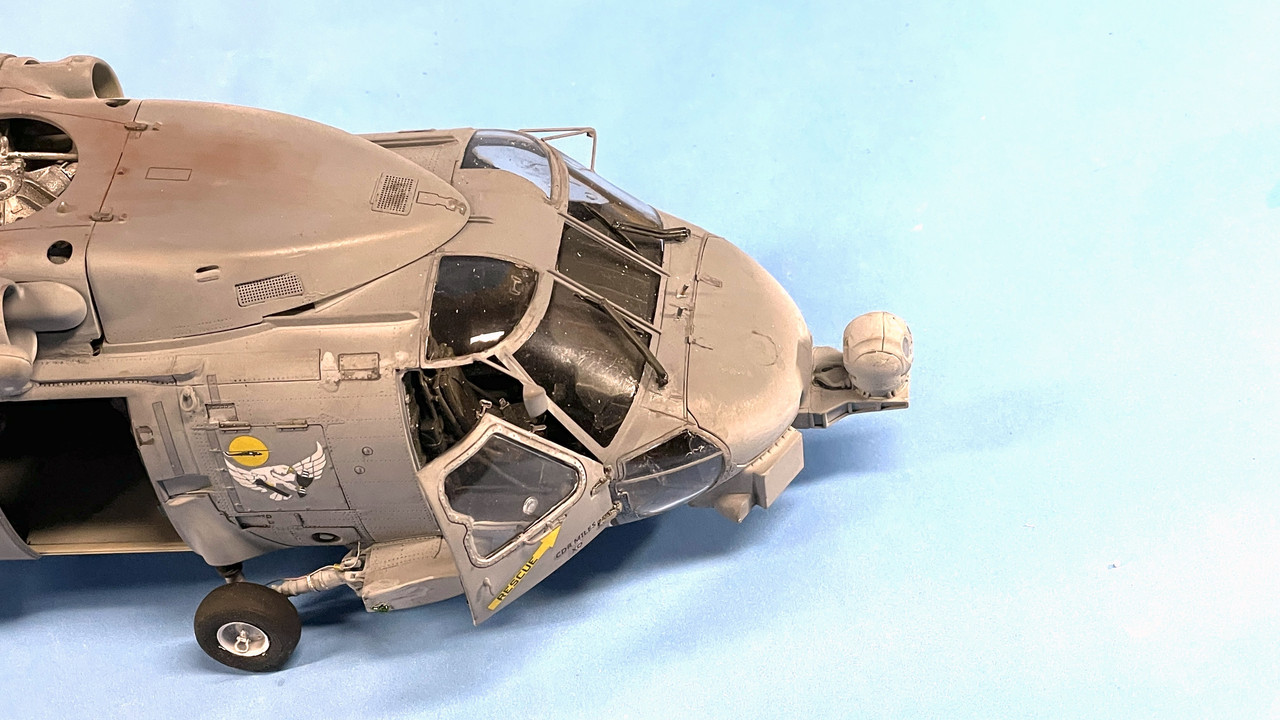
I then got the wipers on using the wire. Touchy, but not too difficult.

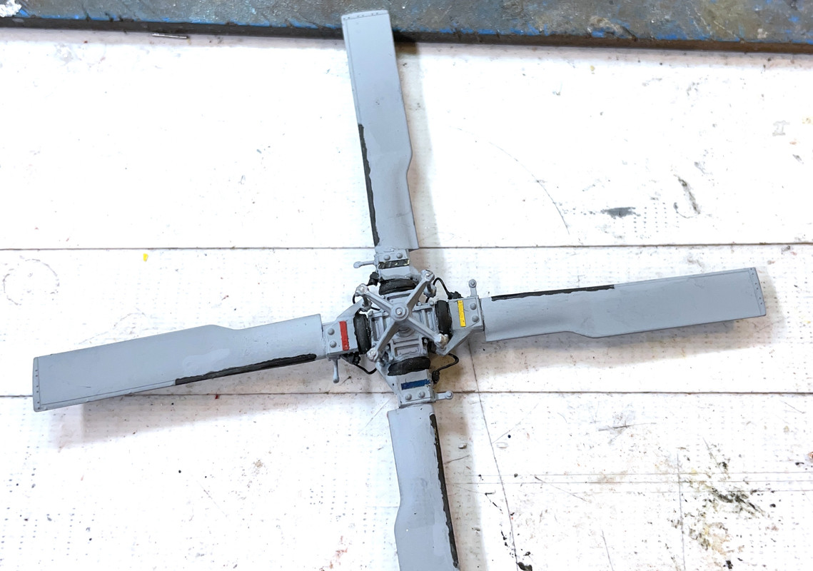
Lastly, based on Svt40’s additional info, I’m adding the color-coding strips to the various places identifying all the blades, their holders and other parts. I painted some Tamiya tape and attempting to use that. It’s not sticking as I wish it should. I think I’ll give it a little patch of clear gloss since things stick to gloss better than flat.

Onward and upward!

It looks like they had to destroy one of these Seahawks in that successful ISIS raid last night. Mechanical troubles. In look how complex these beasts are it’s amazing they work at all.

5 Likes

It was one of those days where I spent 30% of my time doing new stuff and 70% of my time fixing crap that I broke off.

For the new stuff, I built the blade support racks and their associated blade clamps. The kit parts have a very narrow, scale-ish, connection between the forward half of the two-part assemblies and the main part. There are two sets that vary in size. I was seiriously concerned that this narrow part wasn’t going to make it especially after it got softened by the solvent cement in its proximity.

I fixed this by drilling and applying a piece of 0.014 guitar string and a corresponding hole at the correct angle in the main part. I put on accelerator and then pooled some thin CA in the joint. Much, much stonger.

You can’t use sprue cutters to cut guitar string (or any music wire for that matter). It’s so hard it will put nice half-moon dents in the cutters and ruin them. You need a good hardened cutter. I have a Xuron Hard Wire Cutter. But surprisingly, my 30 year-old Channellock long-nose pliers have a cutter near the hinge and cut hard wire with no damage. It’s all abou the metallurgy. Chinese tools generally don’t hold up.

The Xuron cutters can’t cut a tiny piece due to the thickness of the jaws, so a bit was sticking out the bottom of the assembly. This will imapale you so it needed to be removed. I used the Dremel with a diamond-coated burr. Took my time and didn’t grind away the much softer plastic surrounding the wire.

The blade clamps were another small assembly that too much too much time due to the poor engineerig. They needed to be glued together OFF the blade since I’m going to airbrush the entire blade clamp, but I needed it to be spaced as it would be on the blade. I measured the blade’s thickness at the point where the clamps go and then used a piece of cardboard of that width to glue the clamps. When they were reasonably set, I placed them on the blades to finally cure.

Here is the gluing set up.

And here’s all the parts waiting for paint (on Monday).

I glued the rearview mirror back on. First I tried 30 minute epoxy, but it wasn’t viscous enough to stay put and there was no way to clamp it. I wiped off the epoxy and then used some epoxy putty. This worked! It help the part still and cured hard. The mirror is firmly attached. It needs a little cleanup which I’ll do next week.

While fussing with the mirror, I had the model supported on a foam block. It fell off and a main wheel came off, a tailwheel came of and the scissors link broke again. That’s the seond time it broke off since I replaced the original with my 3D printed one. It had become a mess. I still had some printed ones left over, so I made a new one. This one I actually got the hinge wired too. Needs painting.

I painted the main rotor color coding. The tape idea wasn’t working so well. Besides the hub there’s also coding on the swash plate connection links.

Lastly, I got all the loadout items installed. Had to reglue the torpedo. Very small contact area for these parts… i.e., really fragile. This is NOT A TOY! IT IS NOT FOR CHILDREN TO PLAY WITH!

So, that was a pretty big week! Got a lot done and it’s almost finished. What’s left is putting on the main rotor blades with their stowage clamps, and put on the tail boom in the folded position. I may use epopxy putty on this application due to the small gluing area and the weight of the part.

The blade mounts when you look at a prototype image show a connection into the fuselage to locke them into position. The model does not have this, but I’m going to add it. Otherwise, all those blades are just hanging out there.

All y’all have a nice, safe weekend.

6 Likes

Spent a lot of time today fussing with getting the blades mounted and didn’t finish. I did get the blade racks installed. i found that there was a pin on one end of the bottom member that could go into the holes in the fuselage if there were holes there. There were keyslot-shaped engravings at the correct locations on the strbrd-side. I measured the pin and drilled out those areas. Then I realized that I had put the mounting pins on the wrong end of this member and had all the paint schemes backwards.

I had to make new pin on the rear set using Evergreen round styrene of a very similar diameter. The front one’s pin was intact and I was able to use this. I repainted all their bottoms to conform to the scheme on the rotor head. I also added all the blade clamps before painting. The red was air brushed. The rest was hand painted.

Then came the real fun. Getting the kit’s plastic blades into the scale-like attachment points. I was able to use metal pins on all of them without further wrecking the plastic components. Getting these things in was approaching a horror show. At one point I over-torqued one of the hubs and broke it off. I reglued it.

The remaining blade was an hour’s worth of work. Besides using another 3D printed knuckle after I wrecked the first one, I also had to fix where I destroyed the connection journel for the de-icing wiring. I broke the copper wire off from manhandling the knuckles to stay glued. So I re-drilled the tiny hole to reapply the copper. Then it happened again. This time I broke off the carbide tiny drill in the hole and couldn’t get it out meaning I couldn’t redrill it. It’s impossible to re-drill a hole with a chunk of tungsten-carbide buried in it.

I ended up cutting the whole journel off and replacing it with some Albion micro-tubing. That too took wayyyyy to long because I kept losing pieces as I was cutting them off using the razor blade. It was getting late. I was getting tired and hungry and the basement was getting cold.

I finally got that done and next session I’ll get this blade finally mounted.

As you all know by following my work, I generally do not give up. I will keep trying until I get it. Meanwhile, the blades will need repainting due to all the messing around with them.

4 Likes

It’s coming along. Unfortunately, your rotor blades are on backwards.
http://upload.wikimedia.org/wikipedia/commons/8/88/US_Navy_050525-N-0167B-011_An_Aviation_Electronics_Technician_performs_corrosion_control_on_an_HH-60H_Seahawk_helicopter.jpg

3 Likes

OMG! They were such a bear to get on in the first place, AND NOW I TO GET THEM OFF AND DO IT AGAIN!!! UGH!! But it must be done. I’m 3D printing the mating half of the blade knuckle since I’m anticipating having to maybe break something in getting them reversed and I want to replace the damage end with the hole broken out. Wish me luck. I’ll report back when surgery is underway.

2 Likes

Lucky for me and Gino, having spent the time to pin those blades instead of gluing them, I was able to remove the blades reasonably easy without causing much damage or taking too much time.

While trying to get the blades back on I re-torqued the knuckle that I broke yesterday and rebroke it. This time, knowing that more CA wasn’t going to do the trick, I drilled and inserted a 1/32" diameter phos-bronze pin. It was much more secure after regluing.

I got three of the four blades in again. The last one is the one with the 3D printed end. I just printed the mating half which I’ve also pre-prepared with hole positions to pin the parts together and to the end of the blade since I’m also cutting of the battered plastic end. This will give me two good eyes into which I will put the mounting pin.

Tomorrow, the blades will be on I promise. I’m still having trouble positioning them fully folded. The resin knuckles and the plastic blade ends do not conform well to each other. I’ve had to grind away little bits of the blade end to let it swing further towards the hub’s center.

Meawhile, I’m continuing to draw like mad on the Iowa Turret Project. I got the gun loading apparatus finished. This was a very challegning SketchUp task. Here is the cradle in the loading position. The gun is held at 5° during the loading procedure. This gun can be reloaded in 30 seconds.

And here it is in the firing position. There’s still more detail to add around this equipment which I will eventually get to.

Again, I’m fully describing this project elsewhere in the forum.

6 Likes

Good deal. I’m glad the blades weren’t too hard to redo. Looking forward to seeing it all together.

First of all I’m getting this error when trying to enter yesterday’s post in the FSM Forum.

111377277_ScreenShot2022-02-10at1_23_12PM.thumb.png.06b7dd9abe98d40b91868c59d66f5c9c.png

And I can’t seem to enter a new post in the troubleshooting forum. Any ideas?

Secondly, I did (FINALLY) get the four blades attached to the hub. My new parts worked although they still required a styrene spacer and then do some creative carving of both the claw and the rotation motor head on the hub to get the new parts to sit correctly on the hub. Again, the pinning idea was the reason I could do this at all. The hub’s taken quite a beating and will need some TLC to bring it back to it’s prior self.

Here are the two sets of claws. I’m glad I made a bunch since I did use a few before I got it right.

1524273320_SH-60BBladeHubPrints.thumb.jpg.b22b9ac3c61d524da22531ddb7e7caeb.jpg

And here are the four blade facing in the correct direction. The broken hub came loose again, but the pin I inserted kept it in position. I’m letting it float until I put the blades into their racks and then I’ll hit it with some CA. I have to hook up the blade deicer lines and repaint the rest that show their underlying copper. Actually, considering the abuse it took and the number of times I dropped it on the floor, the fact that it looks this good is a minor miracle. I have to put back most of those PE straps on the ends of the blade lock indicators. I have to touch up the blade paint, detail the sensors on the hub end and do some slight weathering on the bolt heads.

124940519_SH-60BBladesON.thumb.jpg.fb087c746e36441a09fe50d80a6f40f5.jpg

2 Likes

No idea on the Finescale Modeler issues.

The rotors are looking good though.

I finished the rotor head, did the repaint, connected the deice lines, and refinished the blades including painting the pop-out nitrogen leak indicator. I also did the anti-collision belly light and finish painted the rear landing gear. I fixed all the blade lock indicators putting on fresh little slivers of PE fret to complete them. They do need some touch up paint. And I notice that I didn’t trim the phos-bronze rotating pins.

There may be a few more areas needing attention such as cleaning up the accent around the blade bolts.

While mounting the rotor and attempting to position the blades into the holders, I broke one of the holders. I also knocked off one of the blade clamps. I drilled both and pinned them.

Ran out of time today to put it all back together. I also broke off the engine hatch by grabbing the model in the wrong spot. It’s a very delicate beast. It will be finished on Monday.

So everyone have a happy Super Bowl Sunday! I’d like Cincy to win, but really don’t care who does as long as it’s a good game that doesn’t embarrass anyone.

6 Likes

Big day! Had a gall bladder imaging session this morning to see if it’s working right and finished the Seahawk this afternoon. Won’t know about the gall bladder for a couple of days, but you’ll learn about the finished Seahawk tonight.

Before putting the rotor on I had to get the tail boom on. I chose to use epoxy putty since there wasn’t much gluing surface for conventional adhesive AND the surfaces themselves were not very secure. I put a wad of putty on the back of the fuze side of the ResKit hinge component and pushed the parts together. Had to hold it for a while by hand and then used some tape. The putty cures pretty fast, and while this was going on I removed a lot of the stuff that had oozed out of the joint all over the place.

After it cured I did more fine cleaning using various dental tools. BTW: you may want to ask you dentist if he has any tools that are no longer usable in the practice, but could be very useful for us modelers. I got a bunch from my dentist. After cleaning I had to go back and touchup paint any areas that degraded during all this fussing.

I did final touchup on the main rotor, trimmed all the extra-long pins that are now holding the blade hubs, and did final finish on all the wires and bits.

I had to repair the rear blade brace since it fractured right near the fuze joint. Don’t know when it happened. I drilled and pinned it. Not easy with the model so far completely and the brace glued to it. Kitty Hawk styrene was a bit brittle and broke way too often way too easily. The rotor went on easily and all the blades aligned perfectly with the braces. Miracle!

I then remembered that I had to add paint and add the missile warning sensors that go onto the port and strbrd EMS pods in front, and the HF antenna wire. I also had to reattach the open engine cover this time with wire. It’s now a bit flexible so you can bump it without it fracturing off. CA is too darn brittle!

For the antenna, I used E-Z Line Lycra inserted into a 0.030" Albion micro tube held with some thin CA. For those that haven’t use E-Z Line, it’s great for rigging antenna and small naval ship rigging. It is hugely elastic and when slightly stretched stays taut. It also glues almost instantly with thin CA. I think it has to do with the huge surface area within the fiber itself. The stands making up the yarn are very fine. The tube was inserted into a hole I drill in the fuze at the antenna entry point. Also a pain in the butt since the model (including the rotor) was already there and in the way.

With that it was done. I still plan on doing the base, but the model stands on its own nicely. Here’s the album.

So there you have it. Work started in mid-Oct and ended in mid-Feb about 4 months of pretty intensive work. My opinion of the model:
Pros:

  1. Beautiful surface detail especially with the addition of the ResKit parts.
  2. Lots of choices on build and configuration. (Huge amount of parts still left on many sprues.)
  3. It’s a great model in a great scale. You can really go to town on super-detailing.
    Cons:
  4. Instructions leave something to be desired. Terrible instructions on creating the stowed version
  5. That reversed part HD33 that i had to redraw and 3D print.
  6. Styrene was fragile and broke at the worst possible times. You better be a good problem solver.
  7. The ResKit parts did not mate 100% accurate with the kit’s requiring further problem solving.
  8. Fits - While having the interior as a separate box seemed like a good idea at the time, in reality it made getting a good main joint nearly impossible requiring a lot of filling.

It was singularly the most complex aircraft build I ever did and I’ve been building models almost non-stop since 1954 at my 9th birthday. I’ve made a practice recently to have each project I attempt to push my skills. This project did not disappoint. That said, I love how the rotor head and engine came out. They met the image I had in my mind’s eye and for that all the work was worth it.

8 Likes

Wow! What a wonderful wild and whirly ride you’ve taken us on! — loved every minute — well, excluding drills snapping, parts breaking, and rotors reversing. All said… some really amazing recoveries which lead to Kitty to looking absolutely gorgeous. :star::star::star::star::star:

Thank’s for that ride! :helicopter:
—mike

I’m a little sad. You have finished that beautiful work.

All the process has been amazing and perfectly solved. TBH, the 60 is my fav chopper in any of its versions, and yours is very very nice. Superb finish. Infact, my wife asked me what to buy for me at Valentine’s day and I asked for a MH-60S like yours, but no luck, I got an A-10 instead.

Congratulations.

Fantastic build! Looks great!

A real beauty of a build and its great to see it all together now and looking awesome.