The last image is an update of the left side blanket! ![]()
![]()
The last image is an update of the left side blanket! ![]()
![]()
The side panel turned out great. Btw, I see gold color wiring and pyramid shaped boxed on both side of the panel and is that something you are looking to add also? ![]()
![]()
Are you madness’ fat prey, Mike? ![]()
I know what you mean, but these mini pyramids would be 2,5 mm x 1,5 mm x 1,7 mm, and that’s really too much of a good thing, God save me from that. ![]()
![]()
Last night I had a dream … ![]()

One should never say never … ![]()
![]()
Hello everybody and thanks for liking, ![]()
the procedures are familiar from the right side, i.e. first the marking of the tape strips and their attachment at the blanket. ![]()


After this stressful puzzle work, it was time to determine the dimensions of the modules again,

which I first have drawn on cardboard (0,5 mm), only this time on the left side there are 14 modules, which I have checked off in green on my template so that I don’t lose track and none are forgotten. ![]()
Then all modules were cut out, ![]() and placed on the template for testing.
and placed on the template for testing. ![]()

Then it was time to glue all modules onto the aluminium foil.

I don’t feel like doing anything more today, ![]() because I want one time to go to bed earlier than usual too.
because I want one time to go to bed earlier than usual too. ![]()
Hopefully I have a nice dream, ![]() tomorrow is another day.
tomorrow is another day. ![]()
![]()
That looked like a good dream with yummy for your tummy!!
Don’t panic, a man without tummy is a cripple. ![]()
![]()
Hello everybody,
first to cut out the 14 modules, ![]() which was again a pure game of patience.
which was again a pure game of patience. ![]()
Then I also separated the Blanket at the interface to the Panel rods system.


Then the edges were colored black.


This was followed by the structuring of the modules, partly with the Pigment Liner, or just with a fine needle, as can be seen in this image. ![]()

And just for testing, the modules were placed on the Blanket, what doesn’t look bad at all. ![]()

Gluing it on was again a good training for my eye. ![]()

And when put together, the Blanket looks like this.

Then I’ve added a few missing ‘markings’ and then started gluing the two parts onto the side wall again, starting with the smaller upper half. ![]()
For this but I had to go back to see how I did it with the special holder, ![]()

but what I managed to do it again,

as one can see. ![]()

Then everything was to clamp new again to glue the lower Blanket part. ![]()

But what once has proven itself, really couldn’t go wrong. ![]()

And so it was too,


and so I was absolutely thrilled with my work. ![]()
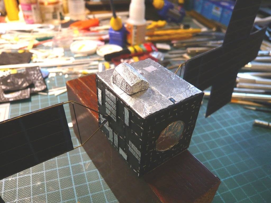
Now I can calmly turn to the Blanket for the front side, which admittedly does not have any Modules, but does have a few tricky details such as this awe-inspiring cannon-like Deep Space Optical Communications (DSOC), ![]()
whereby I will be content with the simplified model form from the video,

which should become tricky enough. ![]()
![]()
So much work going into this … superb effort all round
I agree with John. The amount of detail in this tiny thing is amazing. In the end, I think you might have to change your plans of hanging this from the ceiling and place it under the glass.
Thanks John and Mike, ![]()
I also like this little thing more and more too. ![]()
![]()
Hello everybody,
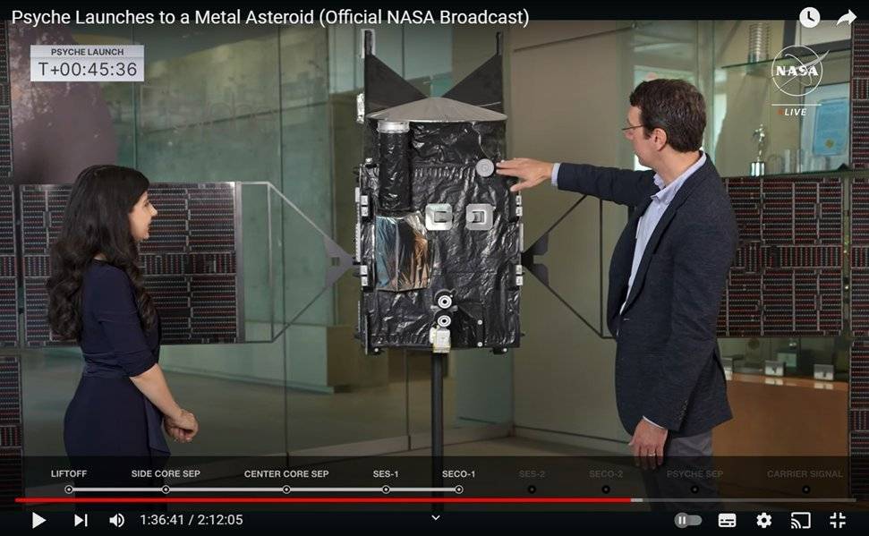
so I took a closer look at the DSOC Flight Laser Transceiver. ![]()
In the NASA model it looks like this, as it was to be seen many times before.

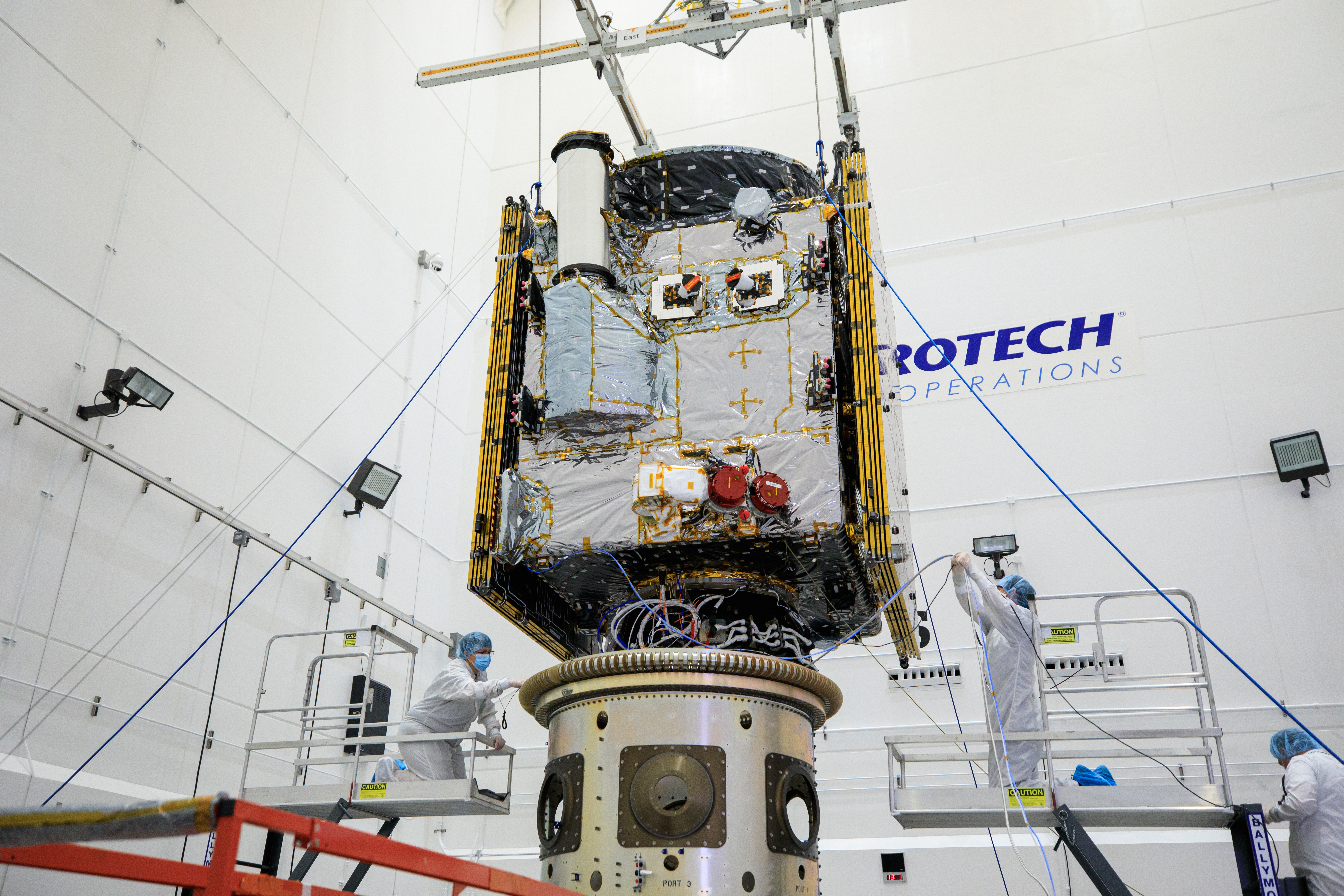
This is an image from end of September 2023, shortly before the start of the mission, which shows the arrangement of the spacecraft on the Payload attach fitting,
via which the spacecraft was connected in the protective Payload fairings to the tip of the Falcon-9 Heavy with the rocket.
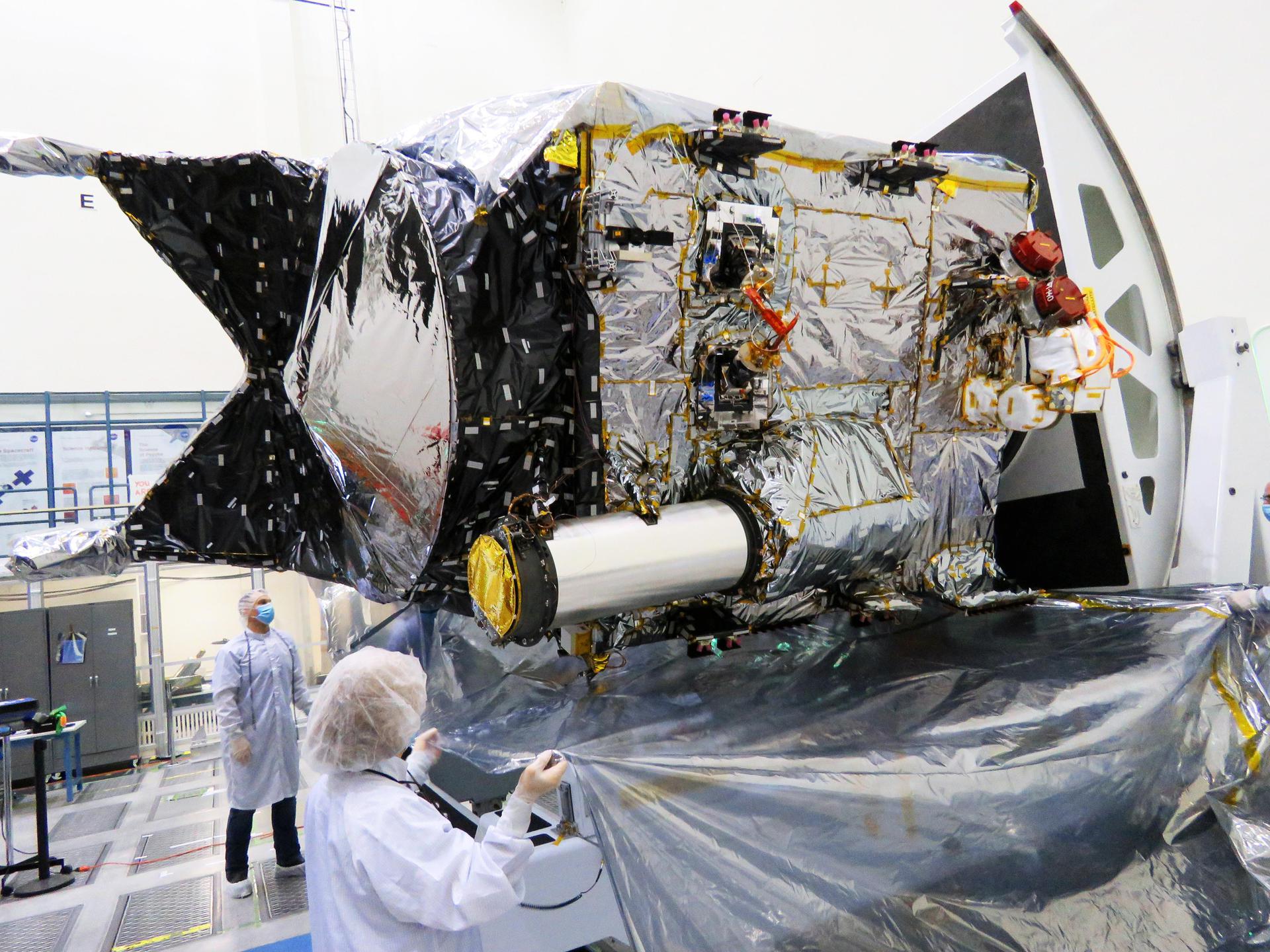
In this earlier photo from December 2021 the spacecraft can be seen in a clean room at the Jet Propulsion Laboratory (JPL) in Southern California.
The tube-like gray/silver tubular part protruding from the side of the spacecraft is the DSOC’s sunshade. The wrapped, unshaped lower bulge to which the sunshade is attached is DSOC’s transceiver, which consists of a near-infrared laser transmitter to send high-rate data to Earth and a sensitive photon-counting camera to receive ground-transmitted low-rate data. ![]()
Just looking at this complex structure initially was rather formidable and looked like tricky. ![]() But to be frightened of it is no option for me, and that is why I thought, whether, how and from what material I could scratch this monster.
But to be frightened of it is no option for me, and that is why I thought, whether, how and from what material I could scratch this monster. ![]()
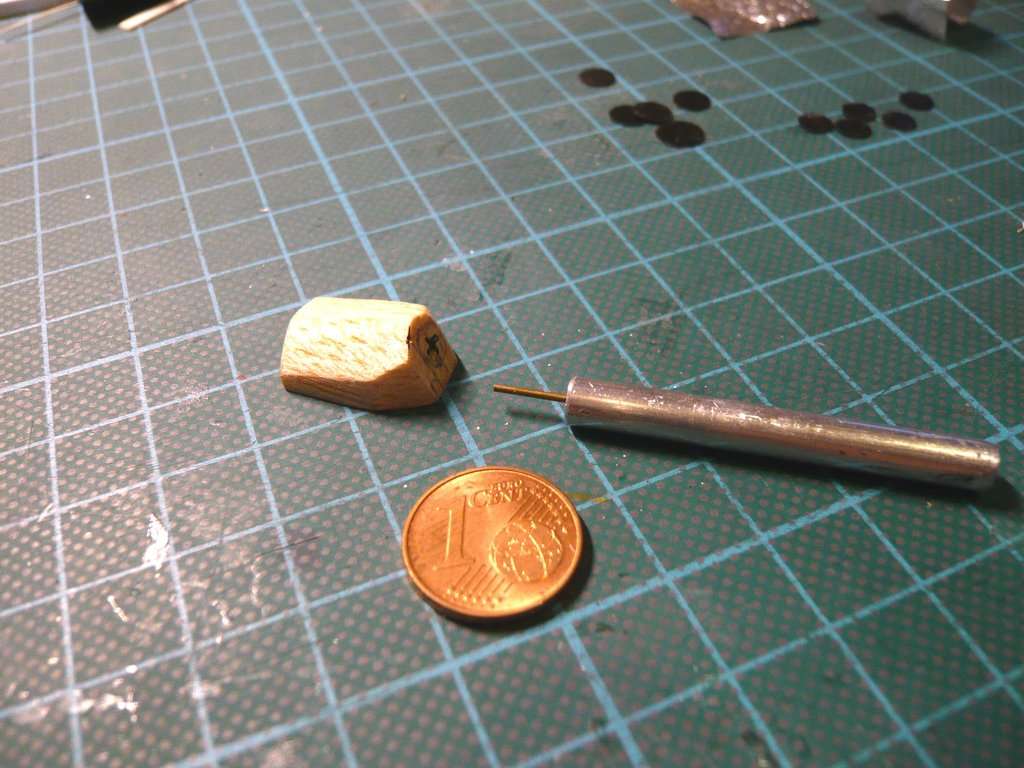
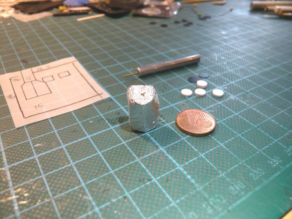
The most difficult part is the unshaped substructure, which I have been considering for a long time on both various original and model photos from different perspectives before I gradually understood its shape and was able to determine the required dimensions for its scratch-building using reference dimensions (length, width, height) of the spacecraft. ![]()
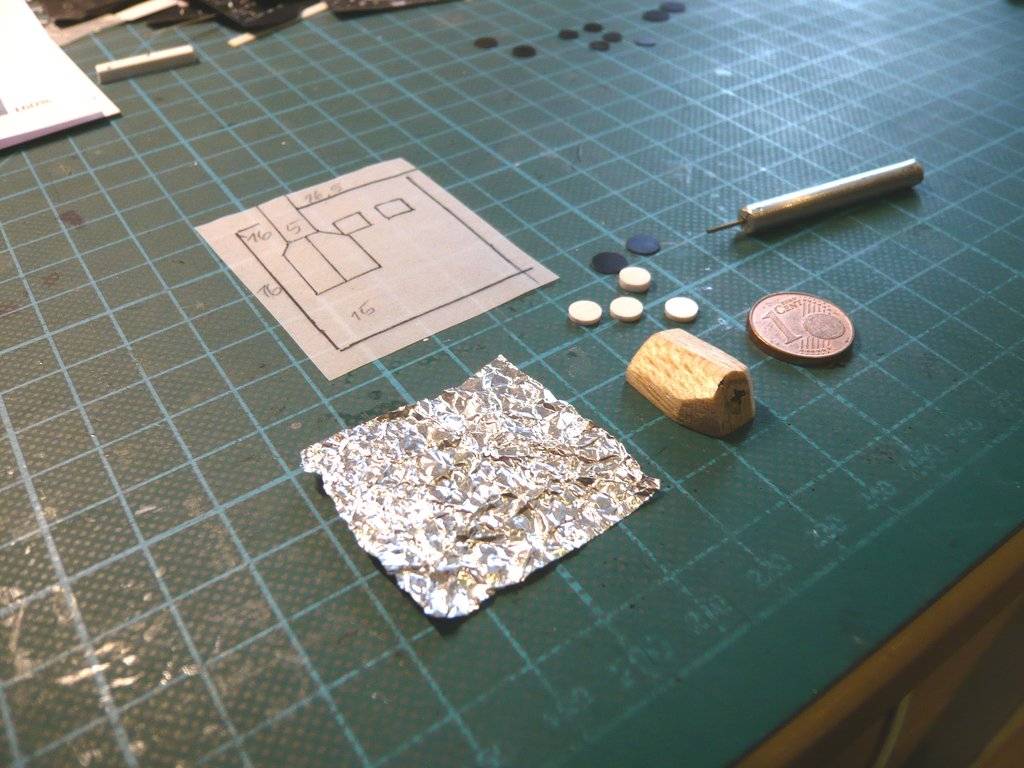
While the sun screen should be relatively easy to manufacture by using a corresponding round rod, I thought of a suitable Balsa block for the asymmetrical, laterally beveled wedge-shaped substructure, which first had to be manufactured/processed accordingly, and in the end “only” would have to be wrapped in aluminum foil. ![]()
An essential aid for understanding the complex shape of the substructure was this photo, which shows the top view, i.e. the top on which the tube-like sun screen is mounted, which allowed me to determine the dimensions and scale them. ![]()

First of all, it was about the design of the side view, which I have corrected and adapted several times. ![]()


On this true-scaled model front side I drew the outline of the substructure so that I could later transfer it to the aluminum foil blanket of the front and cut it out for better gluing the substructure.

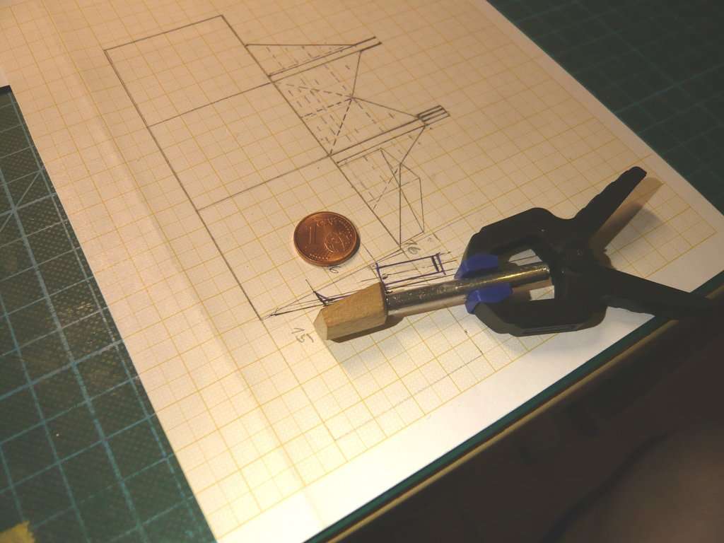
Then I’ve looked for a suitable Balsa block and drew the outline of the side view on it.


Then I started to saw out the longer, slanted contour with a fine saw,

whereby, as always, a stable mount is important. ![]()

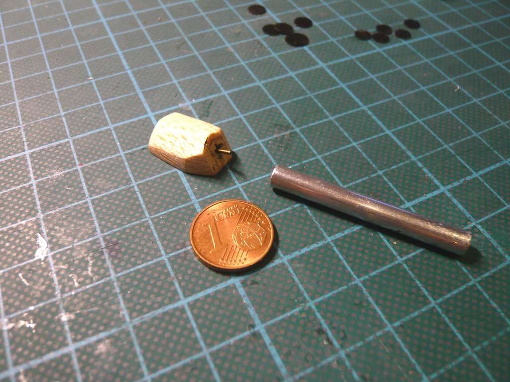
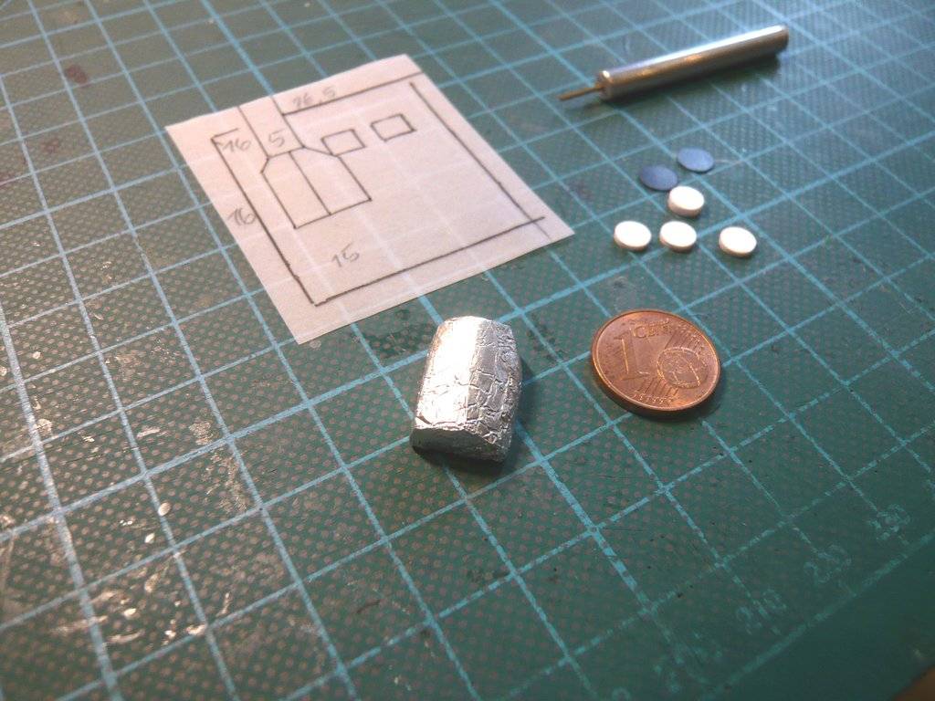
After the first cut was finished,

the upper slant was then sawed off and the blank was smoothed a bit.

And as the test fitting on my sketch shows, that is quite well done.

The next step is to attach the side slants, which may not should become quite so easy, ![]() but the beginning has been made.
but the beginning has been made. ![]()
![]()
Great pictures and nice update ![]()
Thanks John, ![]()
I knew you would like this, stay tuned and have fun. ![]()
![]()
Hello everybody,
and on we go with the tricky DSOC Flight Laser Transceiver, today with its front, which I first transferred to transparent paper, ![]()


to pierce the corner points onto the aluminum foil Blanket.

As one can see already from the previous image, the artificial light is a problem when taking photos which is why I always have to adjust the brightness of images first that are sometimes too dark. ![]()

That’s why I used a small tripod and didn’t take the photo against the lamplight, but once again at a right angle to it,

which looks much better. ![]()

I’ve then cut the footprint of the small DSOC block carefully with the cutter and drawn the areas for the two Star Tracker onto the transparent template,

then pierced it through the foil blanket,

and also cut out, as well as added a round rod (Ø 4 mm) for the Sun screen provisionally. ![]()


Since the sun screen also has a black cap on top, as one can see on this image,

[color=blue]Source: NASA/JPL-Caltech[/color]
I’ve also bought some black silicone hose for it,

with which I can indicate this. ![]()

After that I’ve glued the aluminum foil blanket onto the front side,

and then added the Balsa bottom part,

before the spacecraft has returned back to its safe parking position,

which should be enough for today. ![]()
![]()
Looking good buddy. That photo of your camera in tripod reminds me of my father because he had purchased a Sony camera that looked very similar to yours. He got it from sears locally and I think we still have it someplace. It worked great.
This far in and still finding new bits to add to the already meticulous detailing …great work ![]()
Thanks Mike and John for your nice compliments, ![]()
BTW, it’s an awesome Panasonic LUMIX with MEGA O.I.S./28 mm WIDE for taking fantastic photos. ![]()
Yeah, this little spacecraft with its crazy tricky details is day by day truly a challenge even for me, who is not scratch-building only since yesterday. ![]()
![]()
Hello everybody,
although the sad thoughts of Judy Gale Roberts’s sudden death still run through my mind, I want to come back to the front of the spacecraft, where some details are waiting for me. ![]()
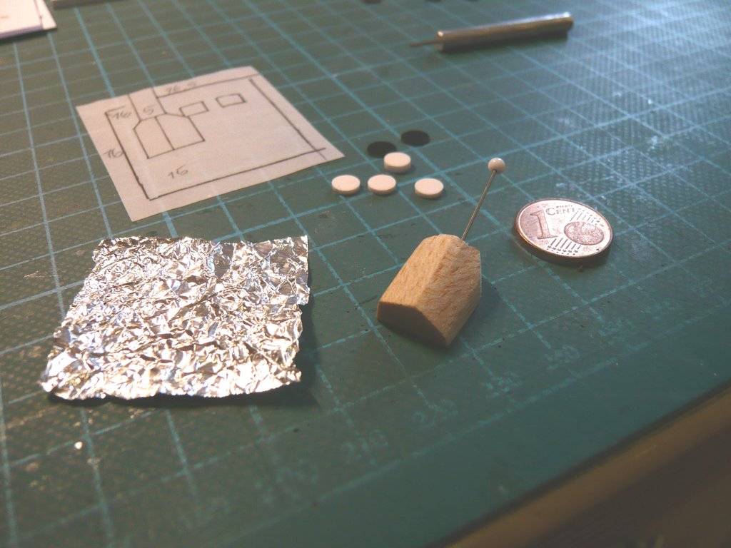
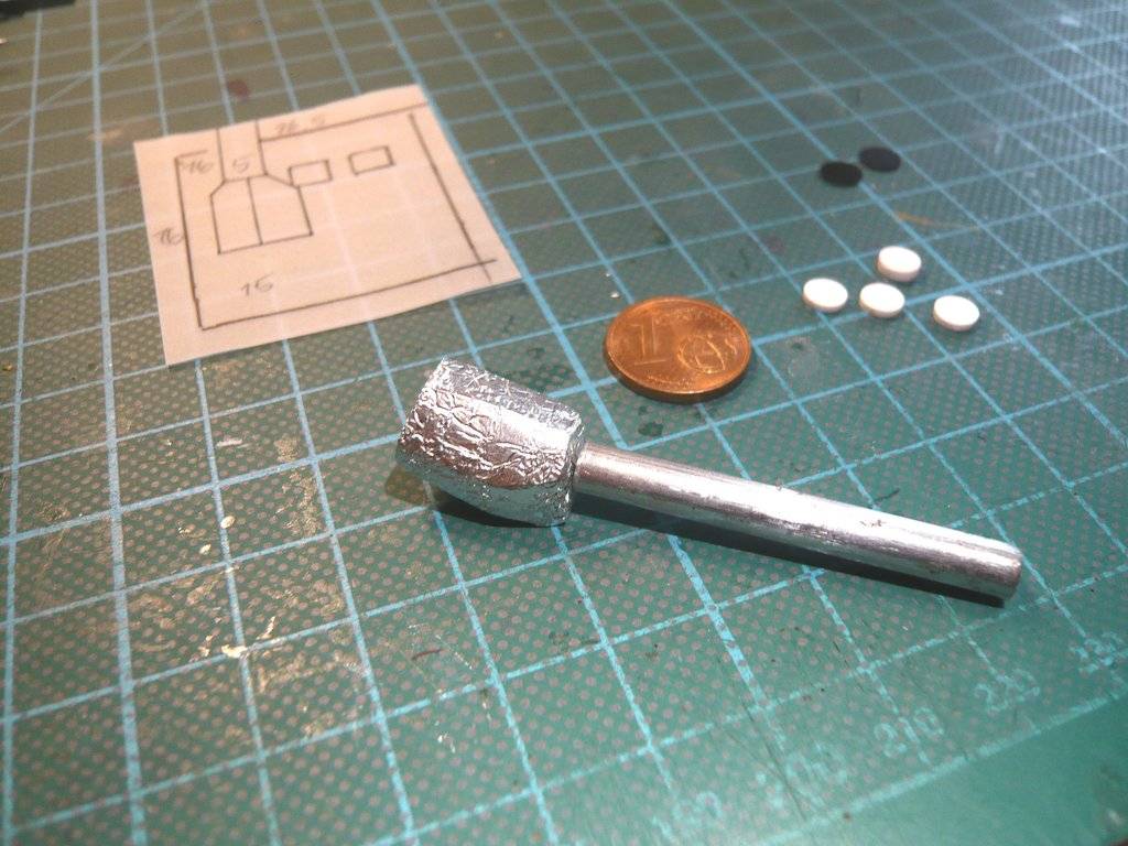
First, I thought about how best to attach the aluminum round rod (Ø 5 mm) for the DSOC sun protection onto the Balsa block for the lower part (DSOC transceiver) so that it has a suitable guide for a stable hold when gluing and sits in the right place straight away. ![]()
And this should be possible with a guide pin, which is why I first drilled out the balsa block by hand with a drill (Ø 0,9 mm) about 8 mm deep,
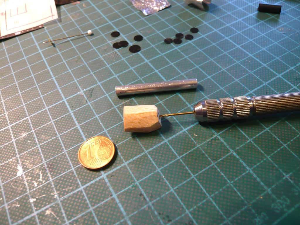
Since I needed a secure holder for drilling the round rod, I clamped it in my mini vice and then started to carefully drill the rod from above by hand.
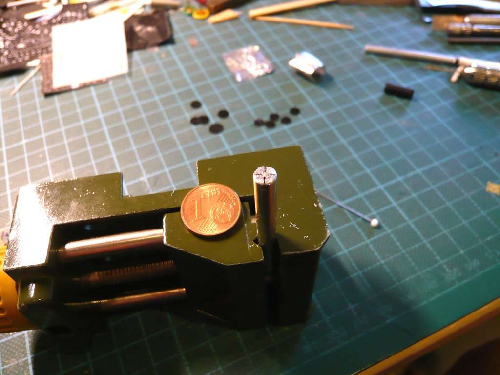
However, since a defined guide is required for the central drilling of the rod, I took out my motor with SAN OU drill chuck B10, 0,6-6 mm, which I had purchased for such horizontal drilling,
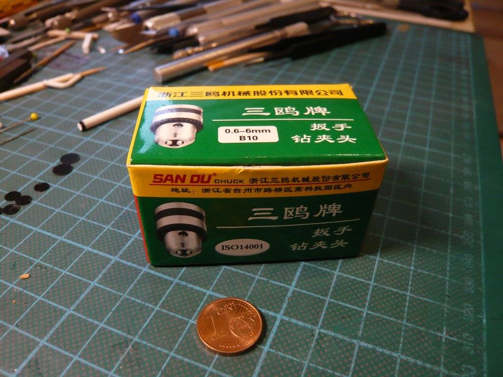
which my friend Arno (McPhönix) upgraded with a rotation speed control. ![]()
After clamping the motor to the table top and adjusting the vice to the exact height, I drilled a same hole of about 5 mm into the round rod at low speed,
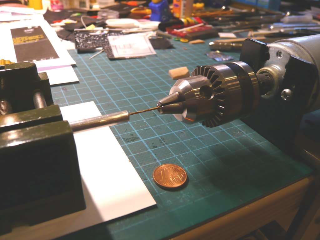
into which a suitable guide pin can now be glued. ![]()
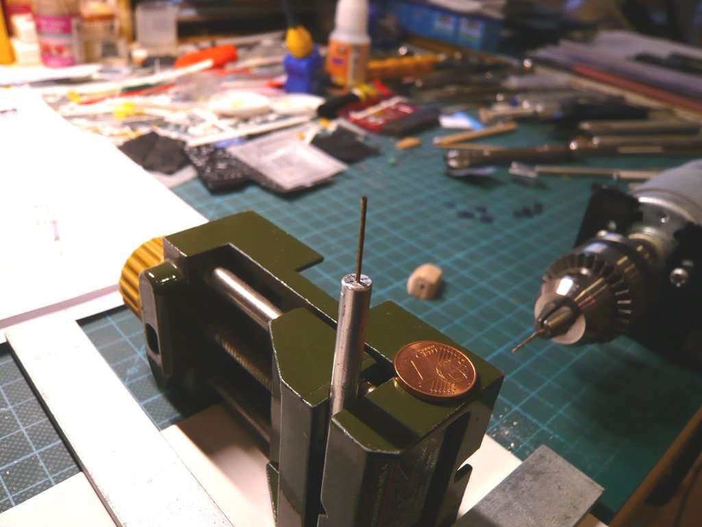
And both should look something like this image.
Then it was time to cover the Balsa bottom part with the blanket made of crumpled aluminum foil, which was quite tricky. ![]()
To glue them together, I pinned the bottom part with a pin for holding,
and then glued the foil step by step with UHU All-Purpose Glue all around,
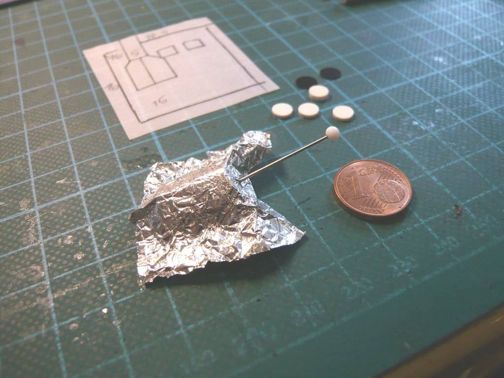
which ultimately worked out quite well. ![]()
Then followed a first fitting of both parts,
as well as the wrapped lower part on the front of the probe, which is already pretty close to what I imagined.
Next time I will come to the sun protection tube, which, unlike the NASA model, is not covered with a black blanket like in this image,
but has no envelopment, as can easily be seen in this original photo.
Therefore, I have to come up with a special solution to be able to scratch the upper and lower black caps too. ![]()
![]()
Hello everybody,
and thus to the individual parts from which I want to scratch-build the tube of the DSOC Sunshade. ![]()
The following images show a bit more of the tiny details, including this black cap with the golden protective blanket on a lid that opens up during operation.
[color=blue]Source: NASA/JPL-Caltech[/color]

I initially wanted to scratch-build this cap by using a black silicone tubing, but I decided against it because it is sitting on a black disk with a slightly larger diameter (6 mm), so I came up with another solution. ![]()
Since you always need a reference dimension (usually yellow in my images) when determining the dimensions for scratch-building,
I measured details of the cap on this section.

Even more important are the dimensions of the entire sunshade of the DSOC, which I wanted to at least structure in a similar way, and whose lower part is constructed in a similar way.
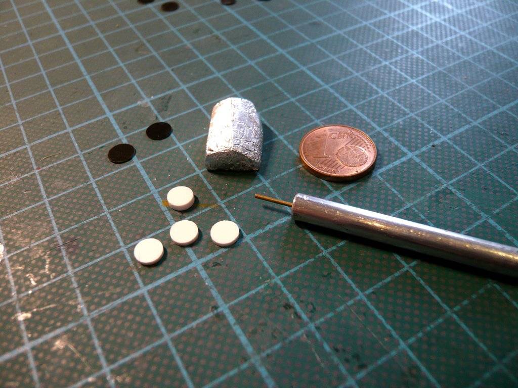
That’s why I wanted to put both ends together from these punched out individual parts that were already to see before, although gluing the different panes together was quite tricky because I had to use UHU superglue for gluing them onto the aluminum rod and I had to roughen up the plastic parts specially for this purpose. ![]()
But see the individual steps for yourself without many words. ![]()


And it’s so easy to make a mistake when trying something on, ![]() because I positioned these two discs on at the bottom the wrong way round onto the rod.
because I positioned these two discs on at the bottom the wrong way round onto the rod. ![]()

The white disk (Ø 5 mm x 1 mm) needs to be fitted with an aluminum blanket strip, which can be clearly seen in this [color=blue]video screenshot[/color], which will be done later.

And so that’s right. ![]()


And now on to gluing the remaining discs for the upper cap with lid, where stable fixation was again important.


The cap was summarily colored black using a Copic Sketch Marker.

Now to the covering the lid with the gold foil from the delicious Lindt praline,

which was shortened on the side,

because there are two hinges there for opening the lid, as seen before, which I wanted to at least hint at. ![]()


Then it was the turn of the [color=blue]foil strip[/color] for covering the sun protection foot.


Then the complete cap was glued.

Then followed the test fitting of the sunshade on the lower part (Transceiver), wherewith the DSOC Flight Laser Transceiver would be complete.


I want to wait to glue this bulky part onto the front of the probe until other missing small parts have been glued too. ![]()
![]()