Douglas A-20G Havoc In Flight

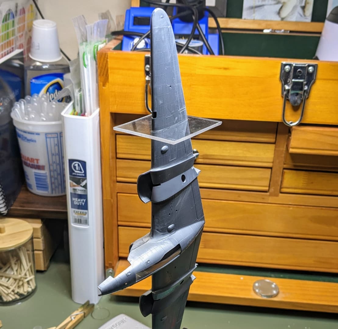
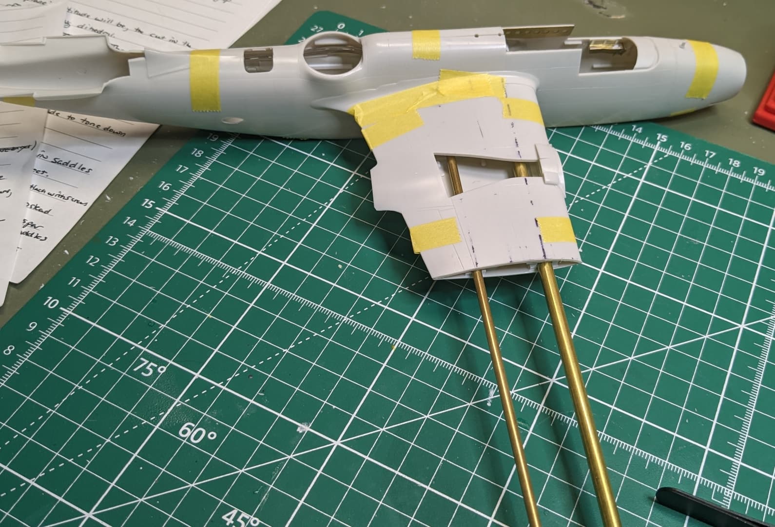
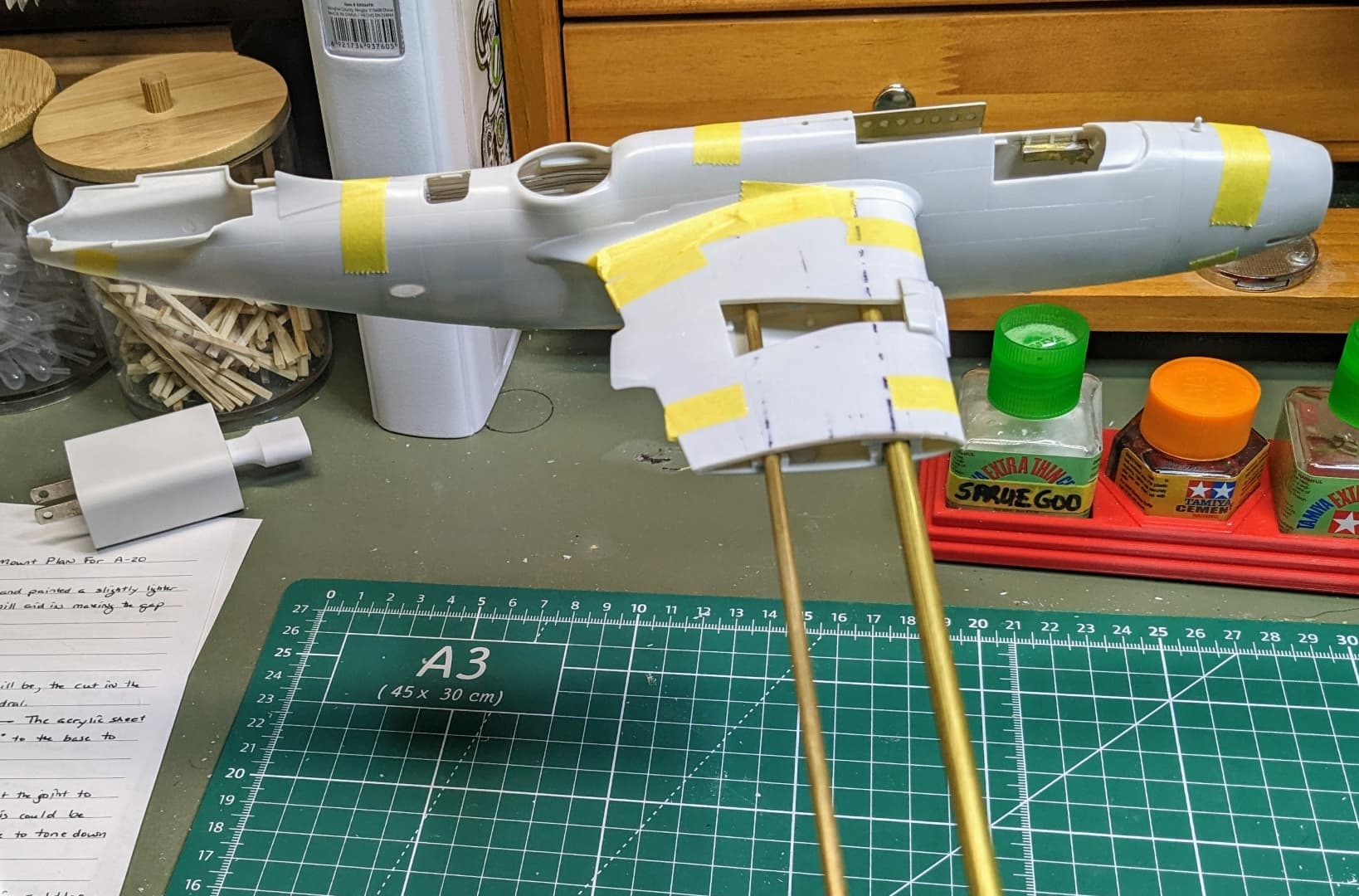
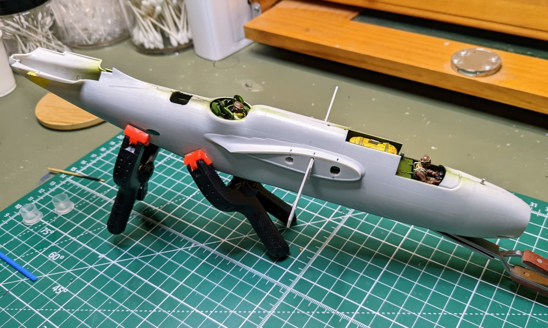
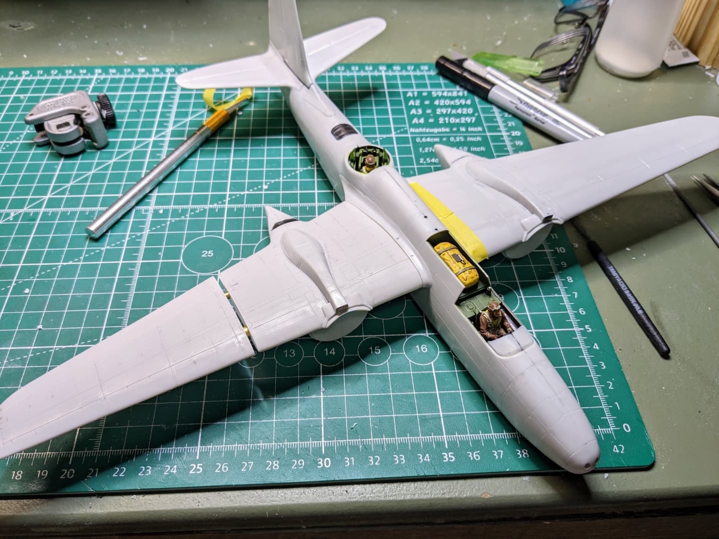
I’ve been somewhat reluctant to return to modeling forums for reasons I won’t go into here, but I decided to give it another try. I’m building AMT’s Douglas A-20G Havoc in 1/48th scale and decided early on that I want to mount this one in flight. I generally prefer in flight models since this is the natural element of aircraft. It does present challenges in how to mount them so that they look nice. Recently, I wanted to find a way to display the aircraft that didn’t involve a post under the plane. I found an approach which I will get into more later that I decided to use with this kit.

I’ll post pictures as I go, but fair warning, I am not the best at taking photos. And although I have been building models since the dinosaurs roamed the earth, it has been in patches of a few years at a time with many dead spaces in between with the latest return occurring in early 2017.

Anyway enough waffling.

The kit, extra parts I will be using (not all of them), and some figures to help me create a crew. I will be representing one of those Southwest Pacific theatre aircraft.

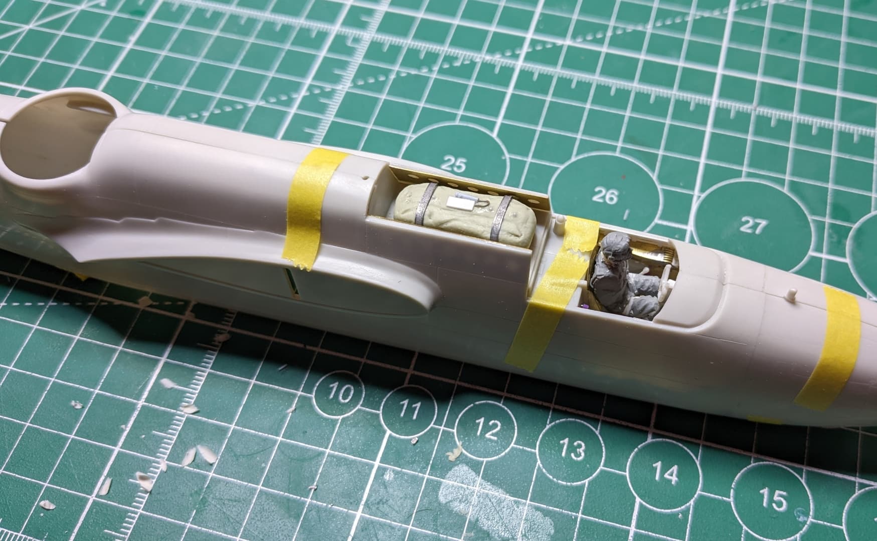
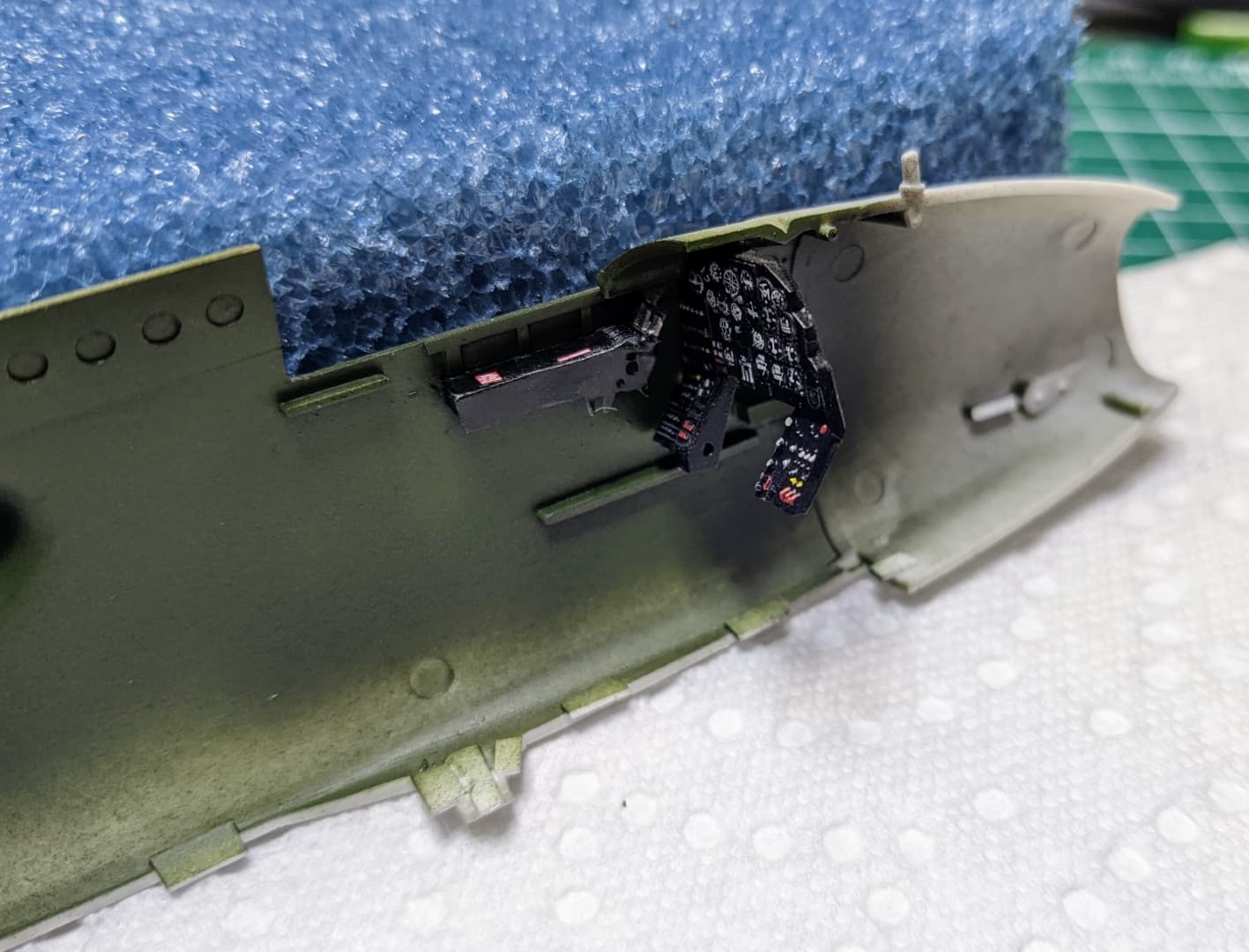
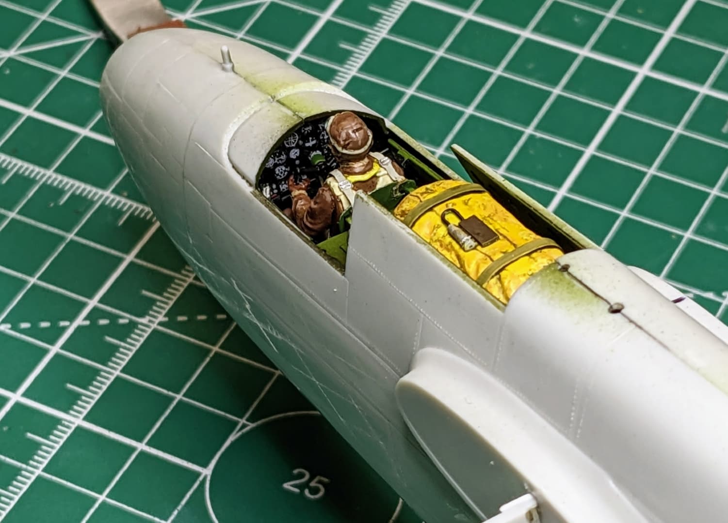
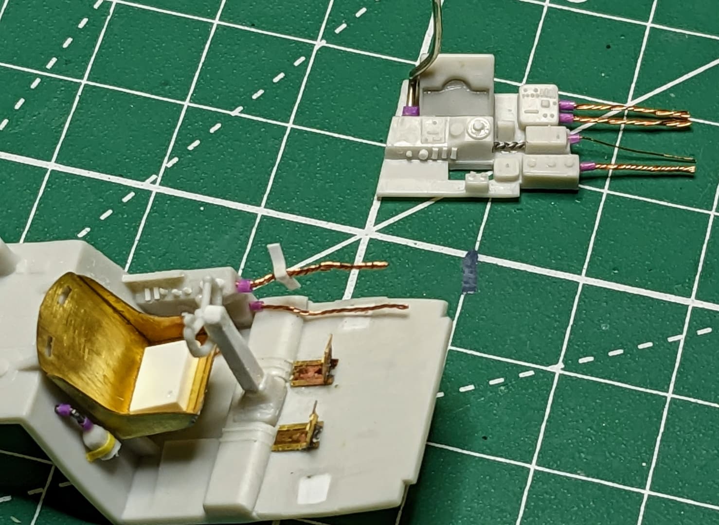
Starting on the cockpit. I tend towards the Imagineering approach to detailing (make it look busy) rather than trying to precisely duplicate the original. I can’t see well enough for the precise approach anymore.

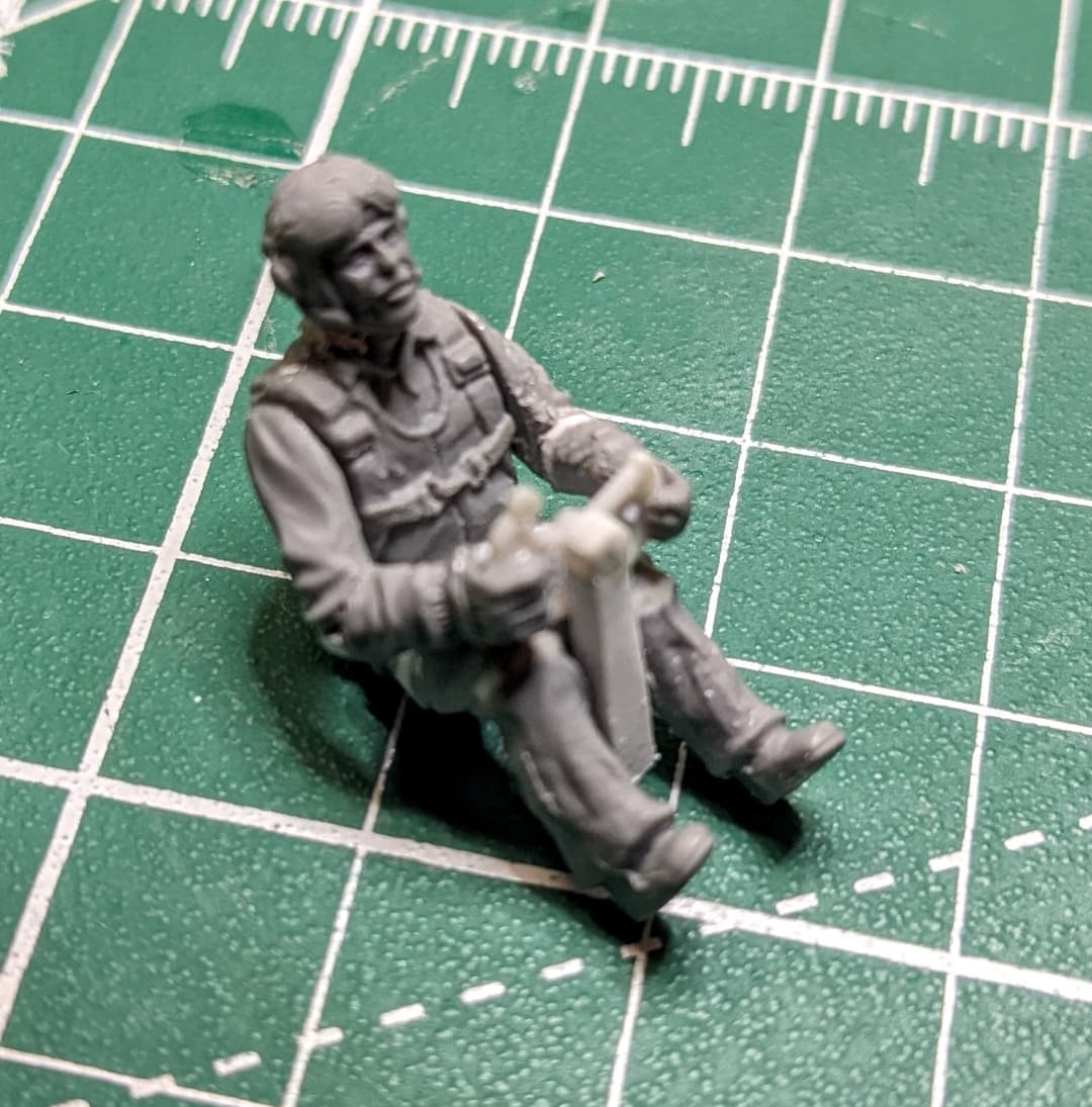
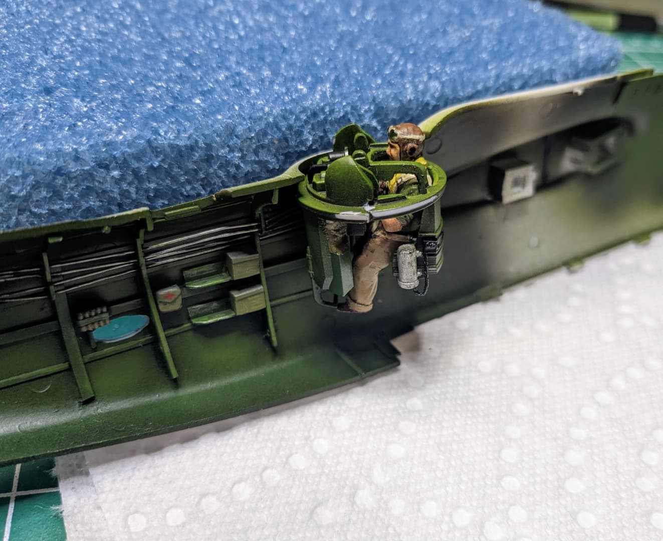
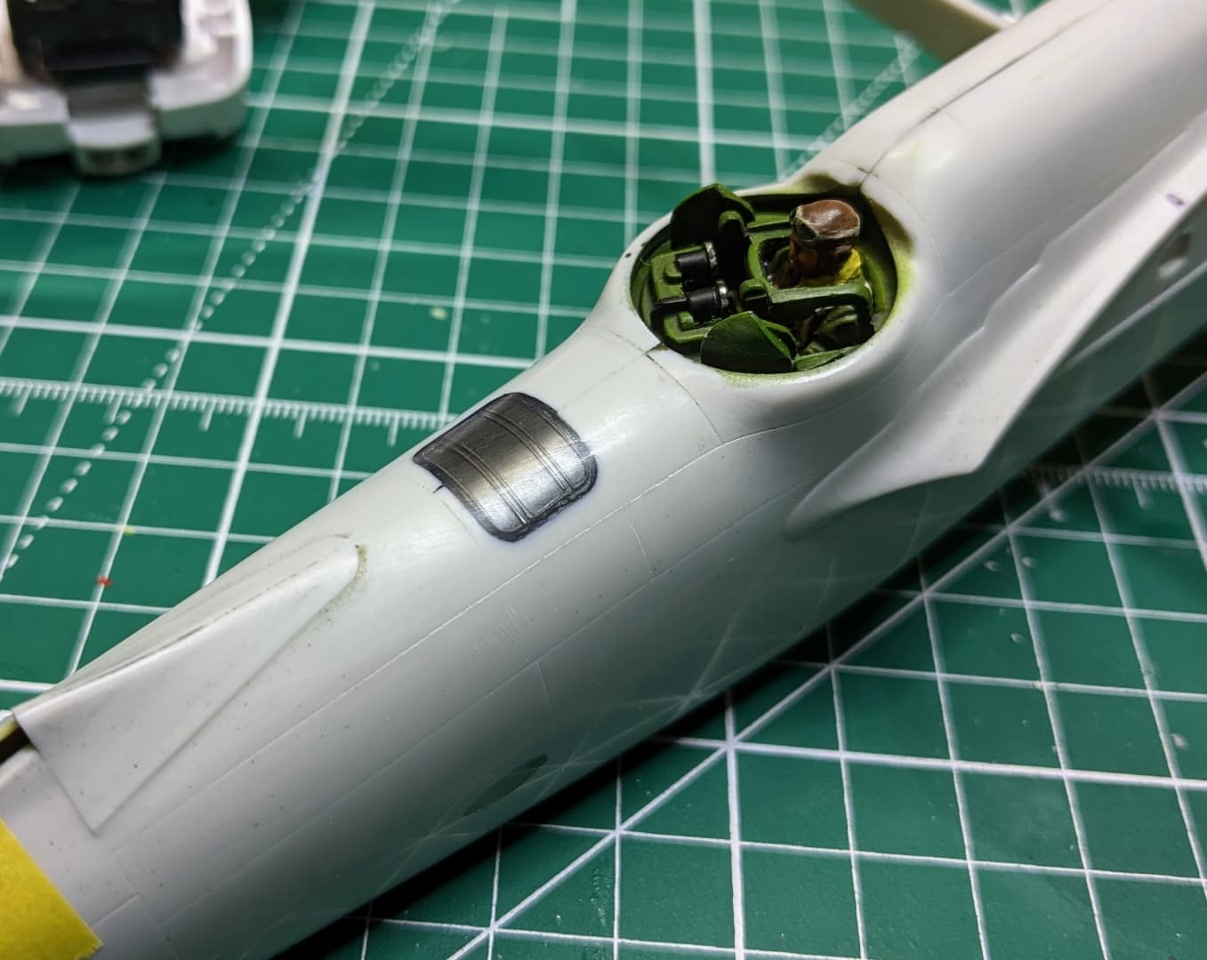
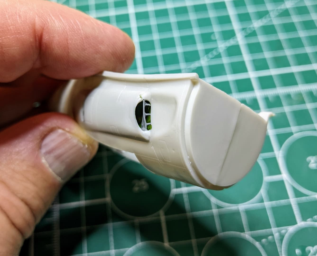
The gun turret figures prominently in this model. I’ll be adding detail and a gunner. The gunner was made by chopping up a standing ICM US Air crew figure so that it would fit.

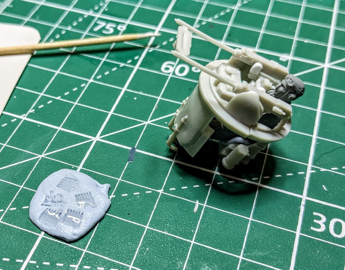
A pilot figure was created in the same way. They look rough now, but they will be cleaned up later

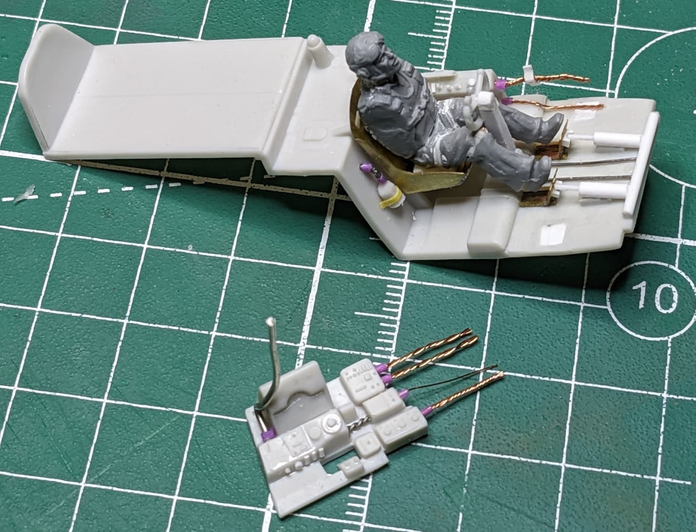
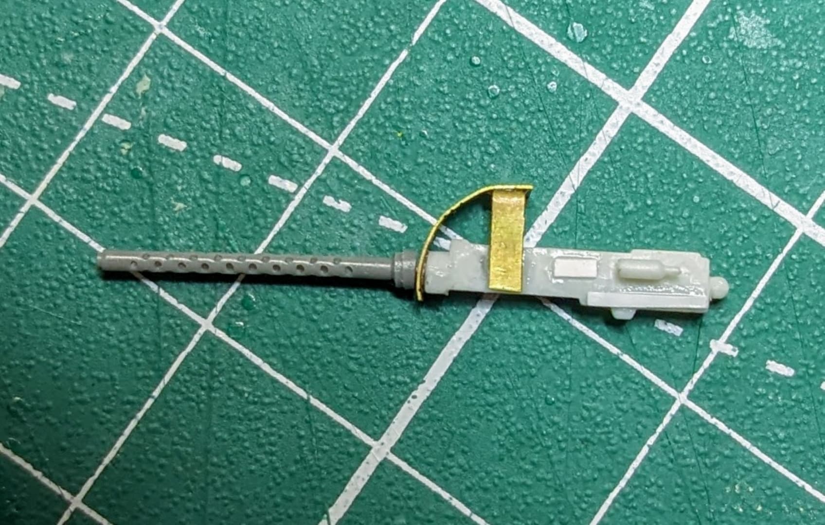
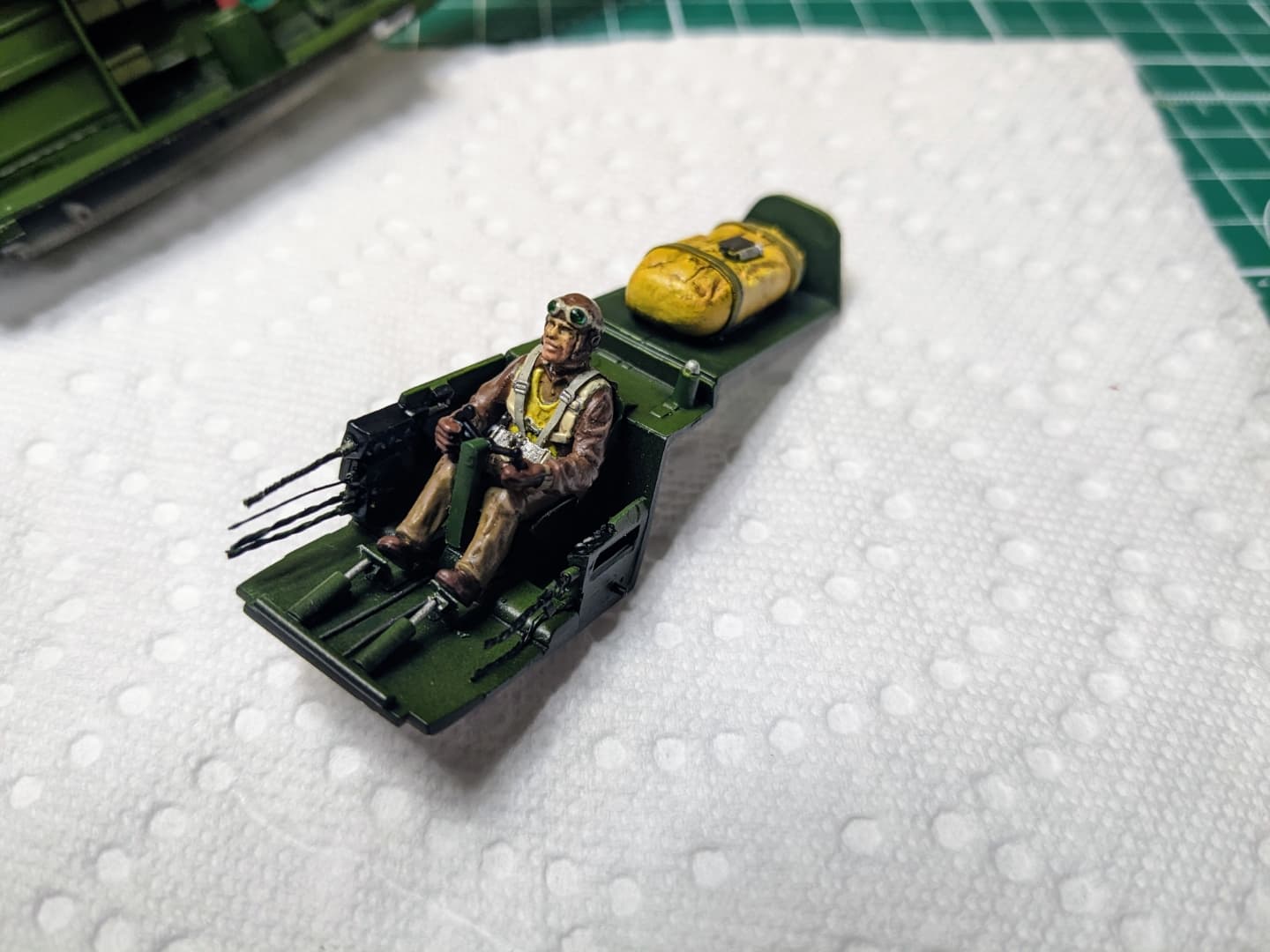
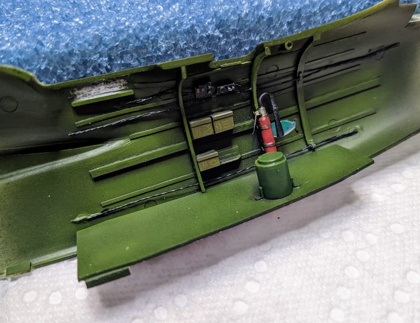
A little more work. The gun belt is photo etch (Eduard if I recall correctly) and will be installed much later in the build. The life raft is my third attempt and is made from epoxy putty.

More to come.

11 Likes

Here’s a bit more progress on the A-20

Test fitting the life raft and cockpit

Adding some busy bits to the gun turret

Adding some framing to the aft cabin. IN no way is this accurate, but you can’t see much of this anyway It’ll look the part.

The kit guns detailed with Quickboost barrels, bits of styrene, and some scrap photoetch.

More detail added to the aft cabin. Most is made from bits of plastic and styrene strip. Various diameter solder is used for the wiring and cables. The small boxes will be ammo containers (eh! they look the part). The small pouch on the lower fuselage half is going to be a medical kit. And the fire extinguisher is probably too big and in the wrong place. Again, you only have the small window at the top of the plane to see all of it and it is quite difficult to see anything.

14 Likes

Welcome Carl and nice intro thread … Nice kit and nice extras.

You’ve made a cracking start. Looks very good. I really like the methodology of adding bits to make it look interesting while they may not be 100% correct … I think you’ve made it work a treat. You are adding some lovely scratch detailing… Will be watching with interest :+1:

1 Like

Thanks Johnny! :grinning:

Okay here’s my plan for mounting the model in flight. I do not take credit for this idea. It’s an approach I saw used by a professional outfit although I am not sure of exactly how they mounted their aircraft. I wanted to mount this plane flying low over the ocean in an attack run (before the attack). The idea is to give the feeling of desperate hope on the part of the crew that they will make it to the target (Think the attack on the Death Star in the original Star Wars movie when they were flying down the canyons)

I could have used a post for this, but the approach I am using hopefully works better and hopefully gives a better impression. The model will be displayed inside a wooden display with acrylic sheets on the sides and top. Below the plane will be the ocean. The main viewing angle will be from the left front quarter (port side). The plane will be mounted slightly at an angle to the display. On the backside of the aircraft, a piece of acrylic will be mounted vertically (inside the display case) running from the aft right corner to the left side of the display. It will be full height of the display cover. As long as the acrylic is clean, it should be fairly invisible when viewed from the outside.

The plane is mounted by cutting a section off the righthand wing (starboard wing) and placing the majority of the aircraft in front of the acrylic. The remainder of the wing will be on the backside. Brass rod is run through the wing (and the acrylic) support the aircraft. The split in the wing will be hidden (as much as is possible) by placing the split outboard of the righthand engine nacelle. More on this in a moment.

Here’s some pictures. so far.

This first pic shows the general arrangement of the display. The dash line represents the acrylic support sheet and the cut point of the wing.

This is a test mule testing out the acrylic sheet on the model. There are a couple of things here to note. There is a visible gap where the acrylic is, but I noticed that it was mainly a darker shade of the aircraft’s color, so I am going to paint that portion in a slightly lighter shade of the aircraft’s color and I think this will help to make it less noticeable. That and the nacelle being in the line of sight should make it acceptable.

This was the scary part, cutting the wing. The dashed lines represent where the brass tubing will go (it has to fit inside the wings)

Testing out the idea and how to mount the tubing. The cut sections will have sheet styrene over the ends to allow hiding the tubing and painting a lighter color as mentioned above.

This gives some idea of how it will work.

10 Likes

Ok, that looks pretty crazy … But a very clever idea… That first cut must been scary lol…

Mounting and displaying it is looking like it will be the hardest part by far …very good luck… It will be impressive for sure… :+1:

1 Like

Here’s some more updates. I did most of this a few months ago, so I am showing a bit at a time. I am not sure how the forum feels about posting a lot of stuff in a single day.

I figured it would be easier to get the pilot attached to the control wheel outside the aircraft instead of after the control stick was installed in the cockpit.

I’m still learning how to paint figures, so this is definitely not up to the same level as I’ve seen elsewhere. Still, it represents the best I have personally done so far.

Gun turret with gunner installed. I’ll add the final details to the turret after painting the model so I can avoid breaking small parts. Other small details in the aft cabin painted. I tested viewing this with the fuselage closed and even with a penlight, not much is visible. Oh well, I know it’s there.

Part of the cockpit including instrument panel. One cool technique I recently learned about and used here was using UV curing clear gloss nail polish for the instrument glass.

More imagineered details

10 Likes

Great update. Depending on trust levels etc, you can post till your heart’s content … Personally I would do posts like your doing…if gives people something to tune into awaiting new updates.

Lovely scratch building as well and the figures look great as well, they fit in perfectly… Great work :+1:

2 Likes

As Sean Connery said in the movie Highlander, “WE ARE BROTHERS”. Astonishing work Sir.

1 Like

Thank you Johnny, I feel like I’m making some progress in my desire to learn figure painting. Someday, I’d like to try a larger scale figure, but that will be a ways off.

HGBarnes said:

As Sean Connery said in the movie Highlander, “WE ARE BROTHERS”. Astonishing work Sir.

Thank you sir!

1 Like

Like all kits, there’s the less desirable side of modeling. It starts with assembly of the main components and the invariable filling and sanding. At the same time it gives you the first opportunities to see how the model is going to shape up. So for me, the boredom of filling and sanding seams is offset by being able to see if I did an acceptable job on the cockpit.


One area I have been practicing as much as possible is striving for a good fit of parts before committing to gluing. But many of these older kits still need some extra lovin’. I’ve been using CA glue as my filler of choice so far. It has the advantage of giving a similar surface to the plastic when it comes to restoring detail, and it doesn’t show ghost seams later on. I’ve learned that the best way to do CA (at least for me) is to apply the CA in small doses, apply accelerator, and then sand it down shortly afterwards.

I learned years ago that clear windows can be blended into the model as long as they are securely glued in. They can be sanded and polished later and finished off with Future acrylic to restore clarity. If I can glue it without worrying about getting glue on the part, I’ll use Tamiya Extra Thin cement. Otherwise I try a variety of alternatives. I recently tried Ammo Ultra Glue on this window. It worked here, but almost caused me to lose one of the small windows on the side, inside the aircraft where I would have never been able to retrieve it.

And if you want to build models in flight, you have to accept the fact that most landing gear doors on kits are meant to be displayed down and rarely fit when glued in the closed position. So that’s when styrene strips to fill gaps are your friend.

8 Likes

More details on the A-20 build. I actually spent quite a bit of time on this part of the build. It has considerably slowed down completion. But I feel it’s all the little details that make it stand out more to me and I get satisfaction from doing the work.

The oil cooler intakes on the nacelles need some reshaping and detailing

All the panel lines needed deepening

There are two sets of lights on the wing tips of the real aircraft. I believe the green and red lights (not shown here) are navigation lights and these lights are formation lights(?). At any rate, they were not on the model other than a scribed line in the wingtip, so I cut them out. Using a small piece of acrylic rod, I drilled a small hole partially into the acrylic to simulate a light bulb, then glued the acrylic to the wing and reshaped it to fit the tip. It will be polished later.

The gun access panel on the side needed rescribing after having to fair in the nose piece to the fuselage. I made a small aluminum scribing template from online plans sized to the correct scale. The aluminum came from an empty soda can. The aluminum is thin enough to contour itself to most curves.

One technique I’ve never done before was adding riveting. I decided to do that to this kit. I used the same online blueprint plans and duplicated it mostly. On a kit this big, it was quite tedious. In actuality, I did most of it on the kit after applying the primer and had to make many corrections and re-applications of primer. But I believe the effort will lend a nice touch to the kit.

13 Likes

What a treasure! Nice riveting work too.

Great update. The bits you are adding are making a big difference. The wing tip lights are really good as is the riveting … very neat work :+1:

HGBarnes said

What a treasure! Nice riveting work too.

Thanks HG. The riveting takes some getting used to. Next time I do it, I think I will do it on the parts before assembly, Both of the wings had seams open in small areas, and I nearly lost one of the small windows inside the fuselage from all the handling.

John said

Great update. The bits you are adding are making a big difference. The wing tip lights are really good as is the riveting … very neat work :+1:

Thanks John. I’m a firm believing in adding the little bits although it gets difficult as I get older. :grinning:
The lights trick I learned from an extraordinary modeler, Rodney Williams.

2 Likes

This is looking fantastic.

Glad I’m not the only one who adopts this approach.

1 Like

Spitfire said:

This is looking fantastic. Glad I’m not the only one who adopts this approach.

Thanks Spitfire! I would love it if I could do more accurate work in this regard, but I recognize my time and skill limitations at this point in my life.

The riveting does indeed make this pop. Would be interested to hear more about your technique.

:beer:

Plenty of help should you need it.

DSC00003 (Small)

3 Likes

I just posted a document yesterday on scaling drawings in the General Discussion area. A good rivet drawing is the first thing you would need. Then it needs to be scaled to the scale of your model. That’s where the document comes in.

I am new to riveting myself, but using the scaled drawing makes it pretty straightforward. I compare each section of the drawing to the model and if the area I want to rivet is the same size as the drawing, then you can get your measurements from the drawing. If not, then determine how many rows of rivets you want to place in that section and divide it’s total width (or length) by the number of sections to get a measurement to each row of rivets. You do have to consider how that lines up with other sections (especially on the wings) and you may find you have to modify the rivet pattern slightly to fit your model. Also be aware that panel lines in the drawings may be in different location (or completely missing) on the model (or the drawing itself may be wrong).

The key is to take your time and think each component through as a whole before starting. I also limited myself to small sections in one sitting as I found that if I went on too long, I started trying to cut corners, invariably messing up and having to make corrections later. This is a bit tedious and will take some time to complete, especially if the model is large.

I used scribing tape, photoetch steel rulers, dymo tape, and sometimes freehand to roll the rivets out using a “Rosie The Riveter” tool. There are other’s out there if you cannot locate that brand. If I recall, I used 0.65 inch teeth spacing, but I suspect each model is different. When rolling, pay attention to where rivet lines end and start.

You don’t need a lot of pressure, but too little pressure won’t be enough either, so practice on a test mule a few times before starting. I found with practice, I could keep the roller straight on shorter runs (without a guide) if I paid attention where I was going towards (instead of watching the roller).

When you get to areas you can’t get into with the roller, you can use a pick, but be aware that it’s easy to over press a pick and get deeper indentations than the wheel. Also pay attention to both sides of the wings or fuselage as most rivet patterns continue around along the same line on the opposite side.

Be prepared to go back with MrSurfacer 500 and dab small amounts over mistakes. Let it dry and sand it smooth up to at least 3000 grit. It is fairly easy to line up the wheel’s teeth on existing rivets indentations to repair a line you had to sand away after the repair.

You’ll probably want to do a very very light sanding overall with a 3000 or finer sanding sponge, and then wash the model before painting. I used an old toothbrush to wash mine.

One thing, I noticed during this process, was that the rivets can look worse up close, but the overall effect when viewed normally is pleasing.

4 Likes

More small details.

IFF Lights - small dimple drilled in fuselage, paint the dimple silver or stainless steel, add a small drop of UV curing glue in each dimple, paint with clear colors (red, green, amber)

Fairing covers for trim tabs on tail surfaces. Small bit of stretched styrene tubing cut at an angle and glued to a flat strip, then glued to the plane. Fiddly, but satisfying. Actuator rods can be added later using stiff wire (if the rod is visible). Also added small bulkhead and simulated bulb under the tail tip formation light cover.


Canopy glued on, still need to do a bit more clean up on this. The canopy was cleaned and dipped in Future, allowed to dry, and then installed. After filling seams, I will have to do a bit of polishing, maybe.
I made an armored glass piece to go under the forward canopy and there are a couple of photoetch parts in there as well. The combing above the instrument panel had some small bits added to make it a bit more interesting.

Testing out the wings. You can see where the one wing is split where it will mount to both sides of the acrylic sheet. I’ll most likely use epoxy for this to ensure it’s strong enough. Not the 5 minute kind (too rubbery).

8 Likes