HMS Thyme and Tide wait for no Flower

Hi all,

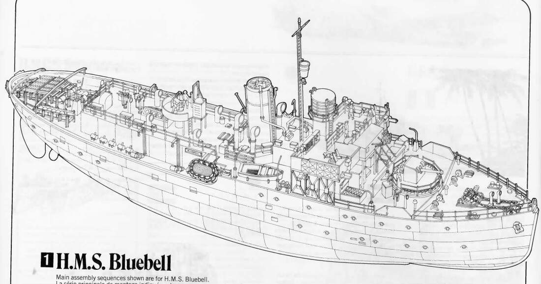
For Christmas SWMBI (She Who Must Be Ignored) treated me to the Revell 1/72nd Flower Class Corvette.

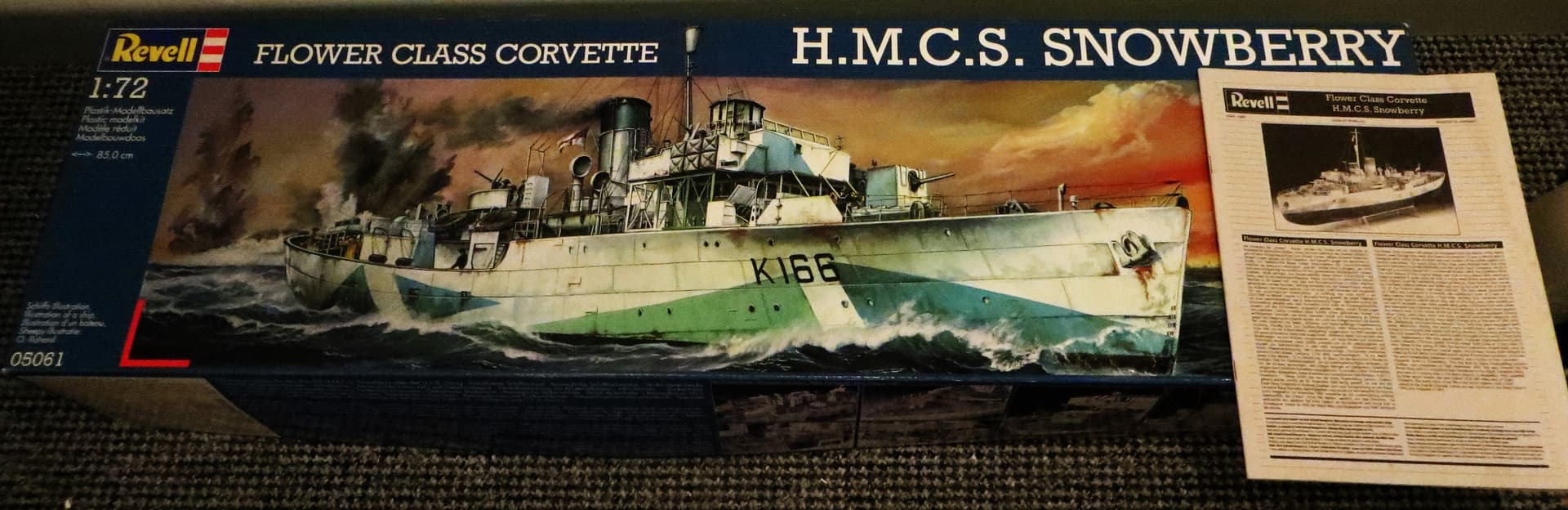
I remember seeing this, as a callow youth, in its original Matchbox guise, and though I coveted it, at the time it was beyond my meagre pocket money.

I’m not typically a builder of floaty things but really fancy having a go at this one. My initial thinking is to try to repurpose the kit as a Royal Navy Flower, if I can find out what the differences are. The idea is to then upsize an idea I’d previously used for the ‘Inaugural Railway Campaign’ started back in 2021 for an A4 sized 1/72nd quayside diorama.

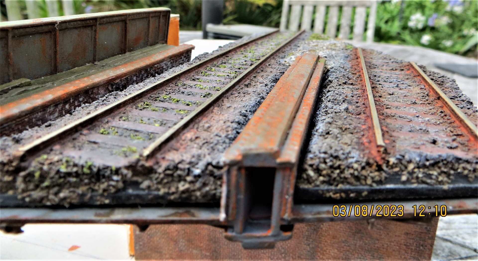
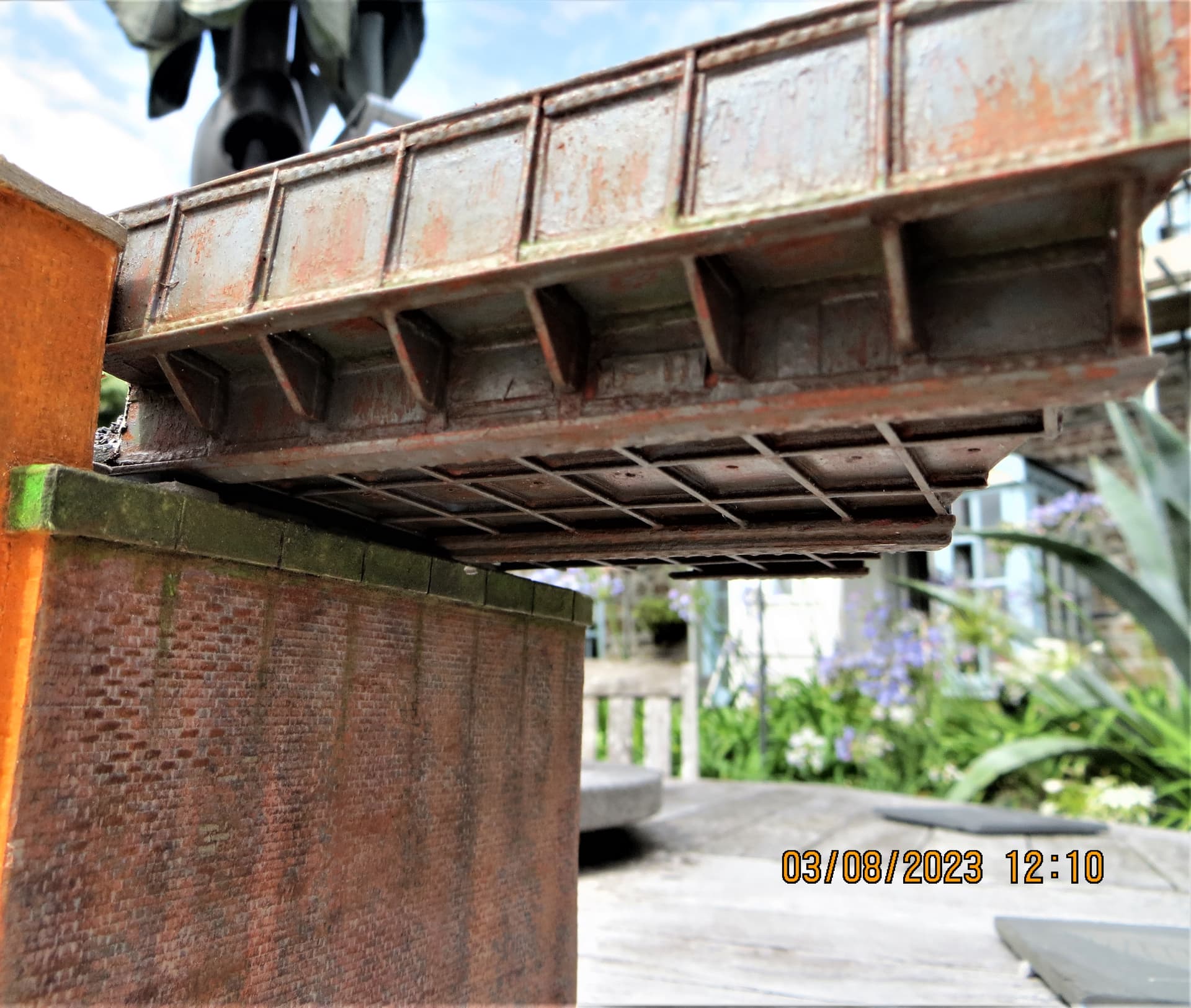
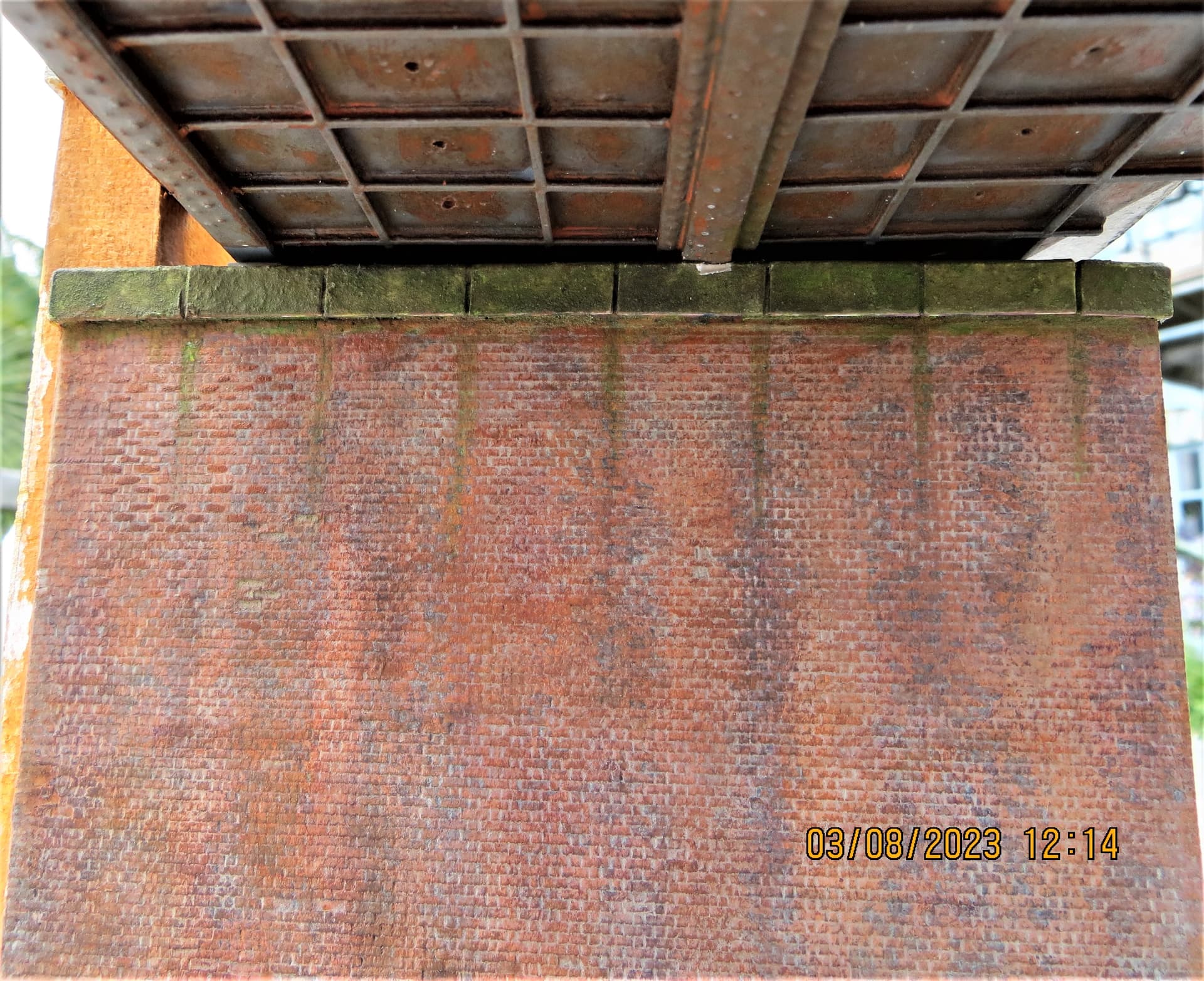
Below are a couple of images of the original diorama (more images can be found in the Inaugural Railway Campaign build).

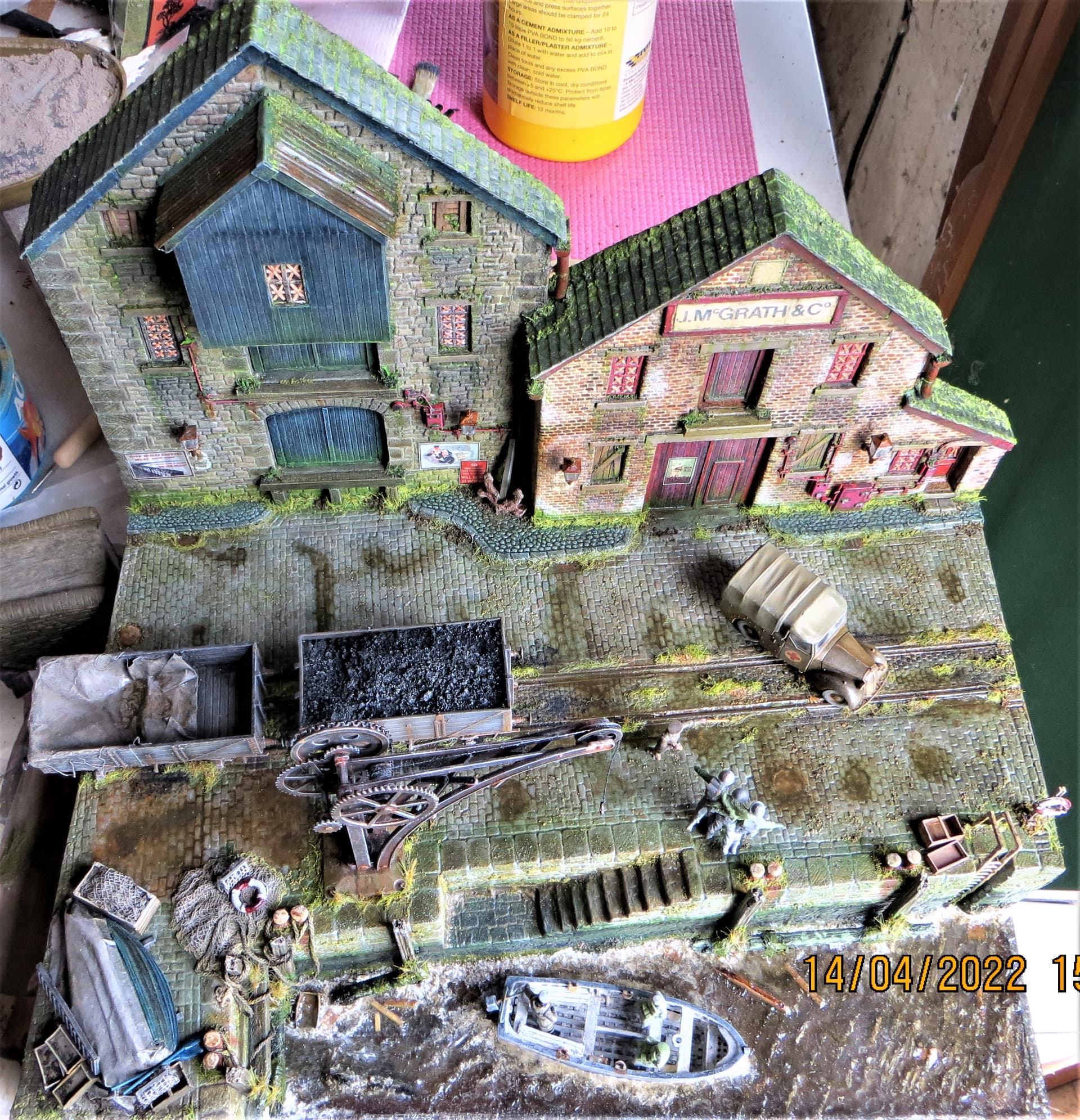
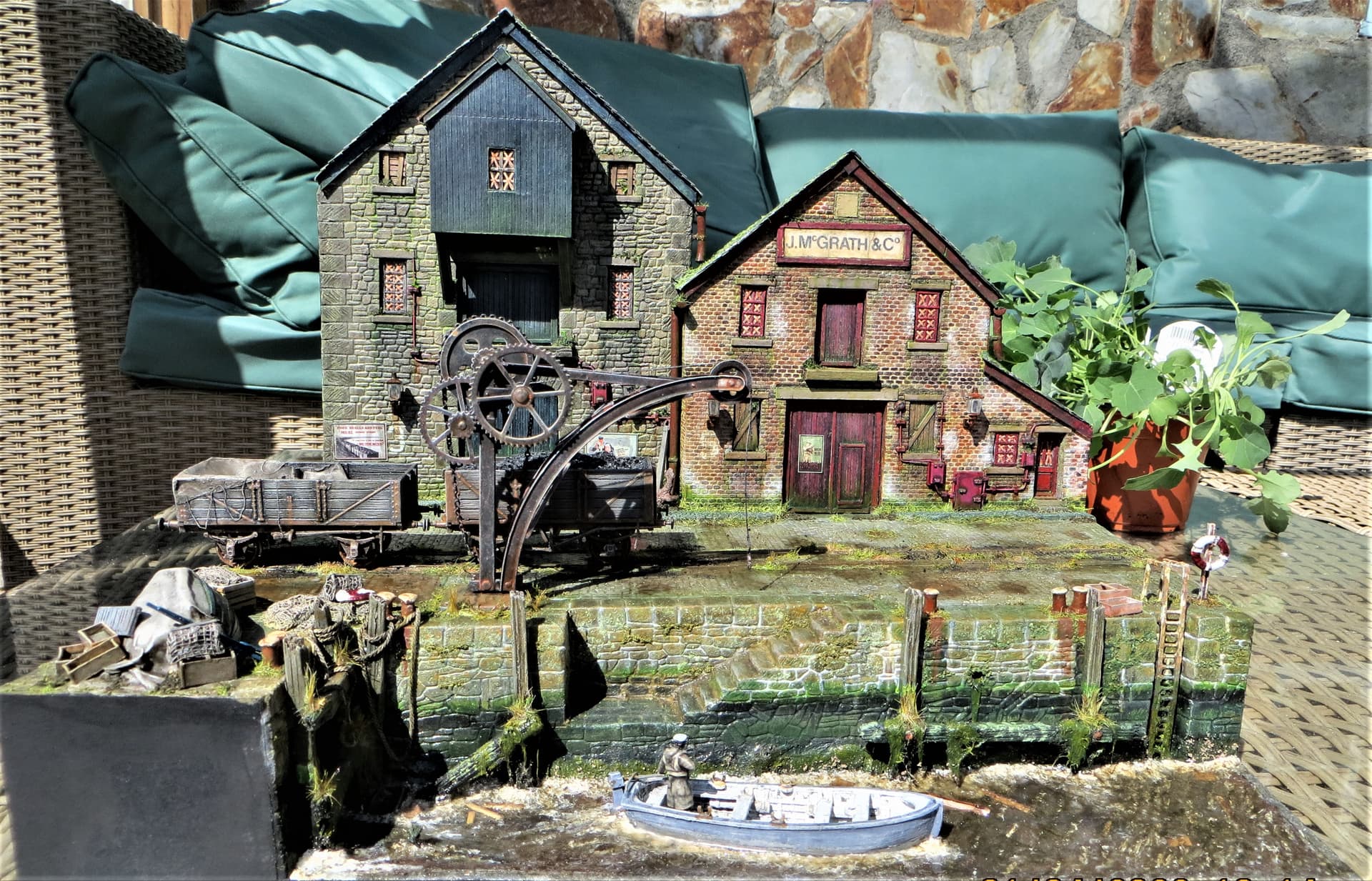
The corvette will be moored alongside the quay.

Being a shipbuilding novice means I’ll probably be asking a lot of dumb questions as I progress throughout the build.

Being both lazy and tight means that much of the vessel will be built OOB, the general exceptions will be relating to any changes needed to achieve a Royal Navy version.

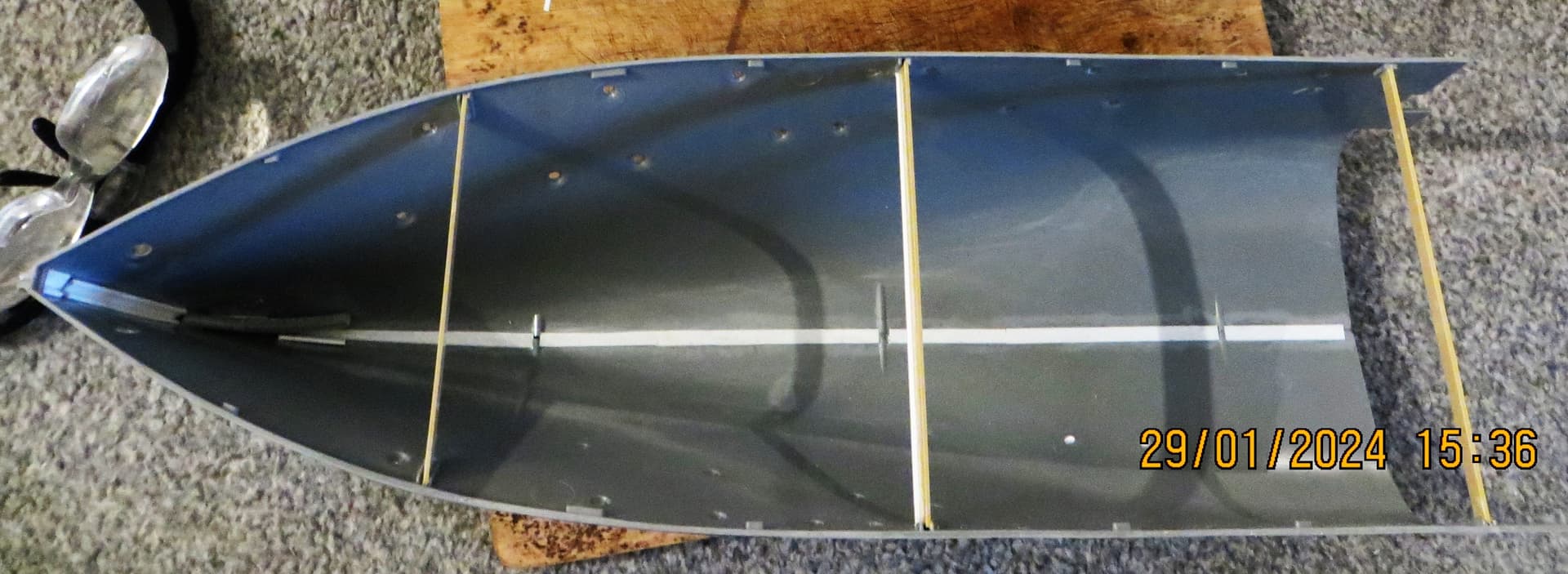
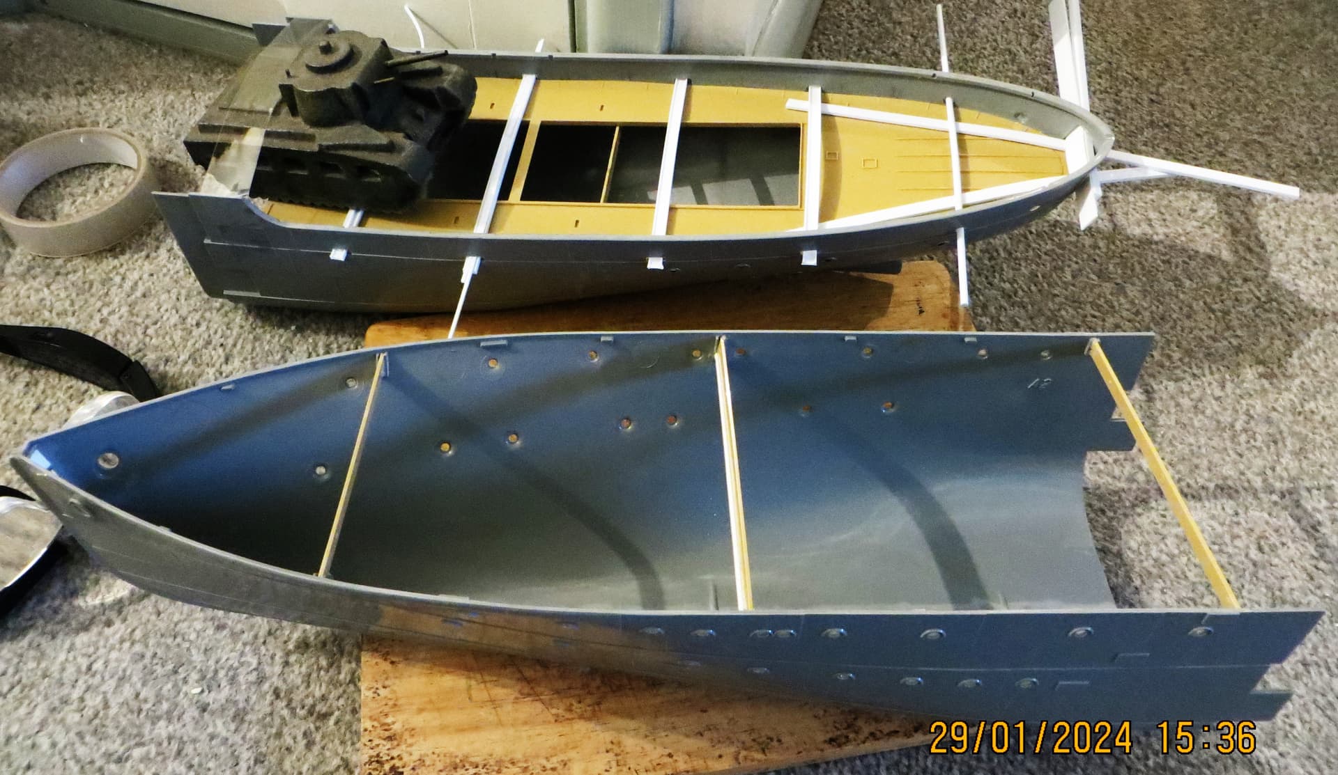
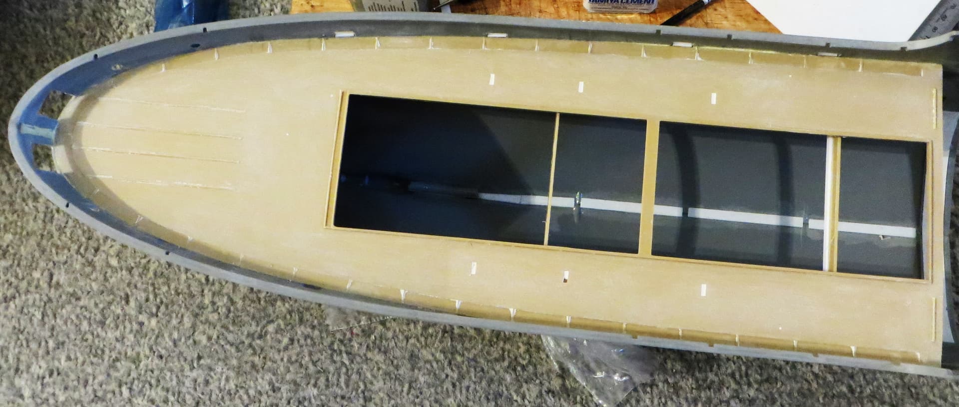
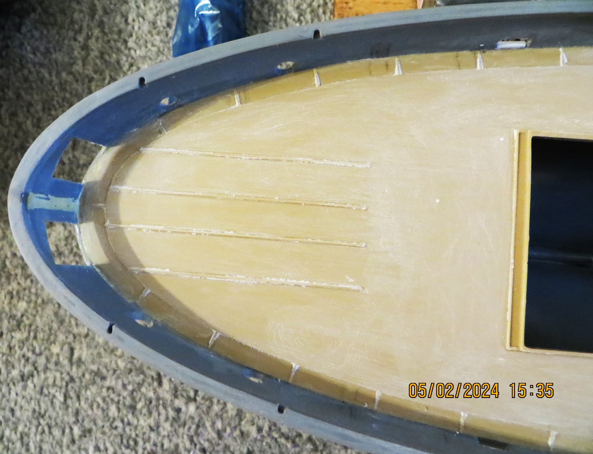
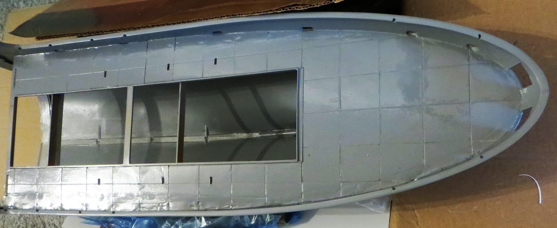
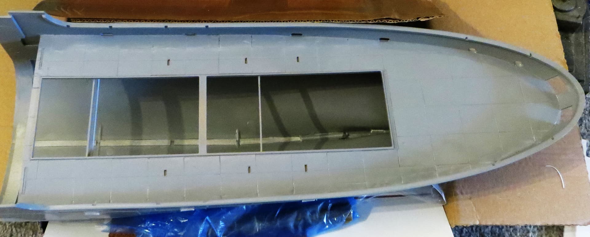
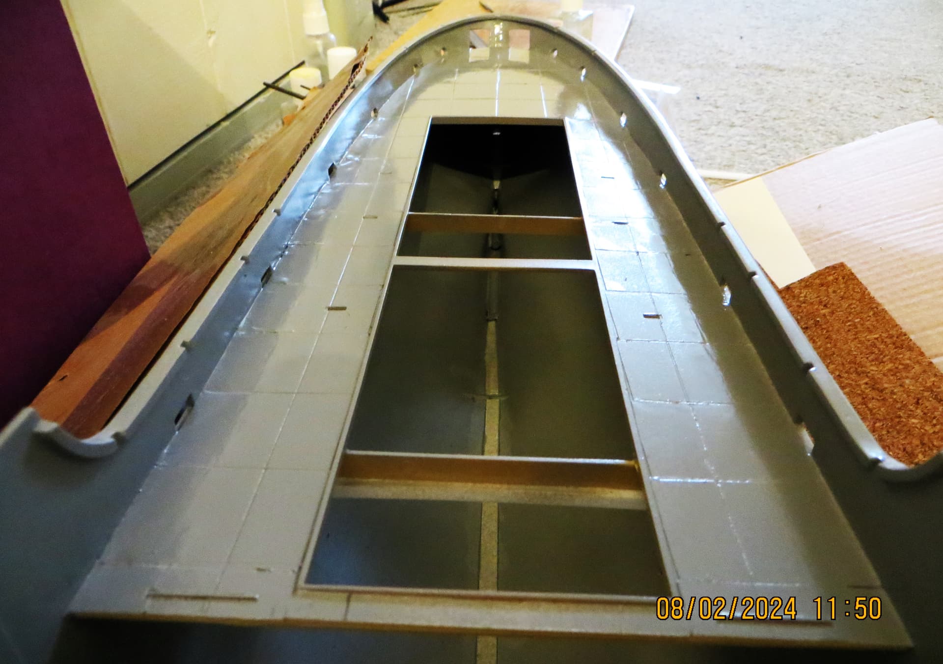
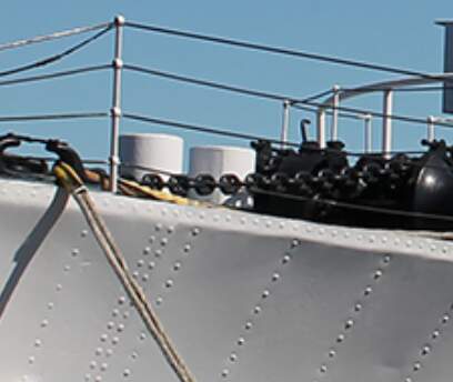
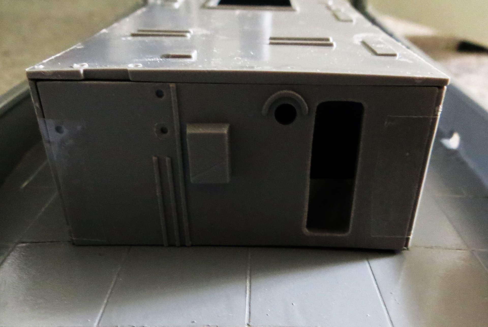
I’m starting with the hull which, I presume, will not need major work, however, the bow of the model looks a tad ‘blunt/bulky’ compared with some of the images I’ve seen online. It might just be the angle of the images, but should the bow be ‘sharper’?

Any, and all help will be greatly appreciated on this one.

Cheers, :beer:,

G

9 Likes

Really looking forward to this! Seen your masterful work on here before, this looks like it’ll be fun! I’ll be keeping an eye on this one.

1 Like

G, I don’t know anything about the ship, but I know what your modeling skills are and I can’t wait for you to start posting.

2 Likes

The parts are all in there. The original Matchbox boxing had three differnet ships in the instruction book, USS Saucy, HMCS Snowberry and HMS Bluebell.
I built the Bluebell back 1982-1983, with radio control, the motor I used was way to powerful and then I switched to a more aggressive propeller (a planing Flower-class corvette is a scary thing to behold, one twitch on the rudder control and she would have keeled over). I had sprained my ankle and was on crutches, bicycling was sort of OK, so I took the bike to the shop, about a mile or so, one week before Christmas, some snow slush on the streets, put that big box on the bicycle cargo rack and pedaled back home.
It was my secret Christmas present to myself :grin:

Download the pdf-instructions here

https://www.scalemates.com/kits/matchbox-pk-901-flower-class-corvette--158864

2 Likes

Great idea G and really looking forward to you getting back into it with this build :+1: :+1:

3 Likes

Thanks to Colin and Fred for their kind words, and to John for the welcome back, :slightly_smiling_face:.

And many thanks to Robin for digging out the old Matchbox instructions, they’ll prove useful, :slightly_smiling_face:.

Thanks again everyone, and cheers,

G :beer:

1 Like

Hi all,

A bit of progress…though not much…probably me, but getting the two hull halves together isn’t easy, you need more than two hands, :unamused:.

I trimmed off all the location pins as they seemed to result in a slight step when used. I then cut some strips of plasticard and glued them internally along the length of one side so that they would overlap the other side. This resulted in a neater mating of the two sides.

Hopefully this will also help reinforce the joints, :thinking:.

Getting the deck to sit right was also a challenge, so decided to pin it down by threading various plastic strips through the scuppers, hopefully this will pin the deck in place whilst the glue takes hold, :thinking:.

Out of interest, the tank was given to me by my grandfather, I think it’s meant to be a Matilda 2, and it’s cast from the original material used for the actual tank, it is extremely heavy for its size, :slightly_smiling_face:.

I have quite a lot of questions, but will be asking them in a separate post for ease of reference at a later stage.

Cheers, :beer:,

G

4 Likes

When I built mine more than 40 years ago I had issues with the fit between the fore and aft hull quarters. The hull plating edges looked extra clunky by the joints.
If they haven’t changed the moulds you may be in for an intense session of dry fitting - sanding/adjusting cycles.
Do not install the rest of the decks before aligning the fore and aft hulls.
I assembled the fore and aft sections of the hull sides before joining the starboard and port sides.

1 Like

Thanks for the heads-up Robin, glad the fit issues might not be just my fault, :slightly_smiling_face:.

Although I’ve assembled fore and aft sections separately I did dry assemble them first using sticky tape so as to ensure they’ll couple together. But you’re right about the ‘chunky’ feel of the plates, so I don’t think the moulds have been changed…but I could be wrong, :unamused:.

I did wonder whether it would be worth trying to reduce the chunkiness of the plating, but I’m thinking that would be a major undertaking, :thinking:?

G, :beer:

1 Like

Nice start G … looks like a ship to me :+1: :+1:

1 Like

A bucket of elbow grease and some sheets of sandpaper would solve it.
Sand the insides of the tabs on the fore halves and the outside of the mating surface of the rear half.
An alternative, adventurous and not for the faint hearted, solution could be to cut off the mating surfaces and replace them with sheet styrene on the inside of the hull once the outside of the hull plating has been adjusted to fit.
Less sanding …

1 Like

Hi all,

Slow progress on the fictitious Flower (yet to be named, :thinking: :slightly_smiling_face:). So much for this starting out as an OOB build, :face_exhaling:, looking, and reading…yes, I can, before anyone asks, :wink:…it would seem that a) the raised plank detail of the wooden deck represented in the kit isn’t well received , and b) many Flowers had steel decks, some with the exception of a small area just in front of the main gun.

Therefore, thinking that a mixed steel and wooden deck would make a nice contrast, I decided to remove the raised detail, the depth charge rails still need to be cut away.

Being a complete novice regarding anything nautical I presumed that the metal deck would not be in one piece, but created from individual plates. However, I have no idea, nor could I find any detailed images showing how the decking was laid, so decided to scribe a rough representation of plating, :thinking: :face_exhaling:.

I’ve given the area a rough undercoat so that I can see any areas that need sanding, and/or filling.

Much of the scribing will be hidden by other elements as the build progresses, but if the above gets a poor reception, or someone comes up with more detail, I can easily fill and re-scribe as necessary…as always, I’m open to your opinions and suggestions.

Whilst trying to find deck details I noticed that the hull plating was very heavily, and very noticeably, rivetted, this is not represented on the kit hull, so wondering whether trying to show this is a step too far, :thinking:.

Cheers, :beer:,

G

5 Likes

IMHO: YES!
The rivets are visible in some lighting conditions.
BUT doing it in scale …
image
The wire rope should be 1½ inch diameter so I think (guesstimate)
the rivet heads are roughly the same, max 1.5 inch.
Being a metric guy I convert the 1.5 inch to 38.1 mm.
Divide by 72 to get 0.53 mm, that’s rather small and there is an awful lot of them.
Producing them will take a lot of time.
Can be purchased £3:58 gets you 30 rivets, there are more than 30 rivets along the
short section of deck edge in the photo above. Maybe 10 quid worth of rivets in that photo.
Doing rivets on the hull would make their absence in lots of other locations even more conspicuous.

You could experiment with other methods like small dabs of glue or enamel.
My life is too short to even think about adding rivets …

Hull plating:
Different shipyards assembled the hull plating differently.
The hull plates overlap each other. (Image nicked from this blog: The White Star Liner TITANIC by Force9 – Trumpeter 1/200 - Page 3 - - Kit build logs for subjects built from 1901 - Present Day - Model Ship World™ and he nicked it from a book)

In-and-Out: Backing pieces are added to the frame.
Joggled: The outer plates have their edges bent to fit over the inner plate. Seen from a distance the hull looks as if has ribbons horizontally and possibly also vertically depending on how the plates in single strake are joined to each other.
Joggled framing: The frame is shaped to substitute for the backing pieces used with In-and-Out
Welded: Will look smooth from a distance and definitely in 1/72 scale

This applies to the Flower class ships as follows (from the Agassiz book):
“The shell consisted of six ‘in and out’ strakes, and different yards used different methods of dealing with the resulting space between the ‘out’ strakes and the frames: Smith’s dock used joggled plates, while other builders used packing pieces or joggled frames.”
Revells hull design looks like packing pieces or joggled frames.
Your invented ship was therefore not built by Smith’s :grin:
The shell plates had different thickness in the different strakes depending on the requirements for strength, ranging from .26 inch to .50 inch or 0.09 mm to 0.17 mm.
Revells plating is therefore very much out of scale.
I would worry about the shell plating before faffing about with rivets, still ONLY my very personal opinion.

2 Likes

There’s someone on one of these modelling boards who says their schoolteacher told them there’s no such thing as a stupid question. Personally, I think going up to a hulking, hairy, tattooed Biker and asking “Does your Granny still do (insert reprehensible activity of choice)?” probably refutes that concept, but in the context of these boards Teacher may well have got it right.
Many years ago a modelling friend (much more skilled than I) built one of these to a museum-quality standard. It was long before there was much resin, let alone 3D, aftermarket existed but he spent a small fortune on PE and White Metal stuff. What plastic from the kit was used seemed to just form a basic shape which functioned as an armature for the PE which sheathed pretty much every surface to the extent that prior to painting the model looked as if it was cast from gold (which might have been a cheaper option). I seem to recall the sloped superstructure over the engine room contained more aftermarket components than there were kit parts used in the entire build…
Although he had assembled a folder of reference photos and scaled drawings of things like guns and winches, I seem to recall his basic go-to was this:

I suspect that there are probably better references available by now but it may still be useful. I believe this publication is well-regarded:
Pen and Sword Books: ShipCraft Special: Flower Class Corvettes - ePub (pen-and-sword.co.uk)

Cheers,

M

2 Likes

Thanks again for the feedback Robin, as always your advice is always appreciated. I did have a thought…dangerous I hear you say, :wink:…that might solve both issues, :thinking:.

Many of the plates are the same size (WxH), so I could purchase two slightly different thicknesses of thin plasticard and cut out panels to clad each plate. I could emboss rivet heads easily on each patch, and at the same time reduce the over exaggerated plating variations, :thinking:.

Not sure if that makes sense, :thinking: :face_exhaling:.

G, :beer:

It does make sense AND it has the advantage of being possible to correct.
Minor mistakes will not be “terminal”, you can always go back and choose another solution.
A helluva lot of rivets though

scroll about halfway down

3 Likes

Thanks for the feedback Tom, and the heads-up on the book, really useful info, :+1: :slightly_smiling_face:.

I did look at the aftermarket stuff for the kit and agree with you about the cost…very prohibitive, especially for a cheapskate like me, :wink:.

Also, I avoid PE like the plague…especially complicated stuff…as I am inept when it comes to working with the stuff, :grin:.

G, :beer:

1 Like

Thanks again Robin, yes it is a lot of rivets, but I’d not be looking to be 100% accurate, it’d be more about giving a representation of riveting, along similar lines to the metal railway bridge I started for another…unfinished…project last year (see below).

G, :beer:

3 Likes

Following with interest, G :slightly_smiling_face:

1 Like

Hi all,

Some small progress, the front part of the deck fixed, and the surface planking removed, metal panels need to be added forward of the pencil line, and planking added below panel line.

I’ve also started to assemble the large structure that sits on the rear deck. This is very flimsy if built as per instructions, so I added some reinforcing ribs for rigidity.

As the finished vessel will be shown alongside a quay I thought that many of the doors would possibly be left open, so have decided to open up one or two. It’s a shame the option wasn’t given in the kit as trying to drill and cut them out isn’t easy as they’re quite thick chunks of plastic.

The deciding factor on the number of doors will be how easy it is for me to recreate the actual door leaves, :thinking: :face_exhaling:.

Cheers, :beer:.

G

4 Likes