Thanks! Yup! Lighting is in the works. The won’t be a ceiling per ce, so the lighting may be attached to the piping. I’m thinking about it.
Yes that’s what worried me, you wouldn’t want it to be obvious (& therefore clearly unrealistic) and there ain’t much spare room from what I can see. Another challenge for your boundless creativity! LED’s inside open pipes…?
The real room was lit by a series of florescent fixtures. I’m not going to install full levels or ceiling so I won’t have the places to hang hang them. I will figure something out.
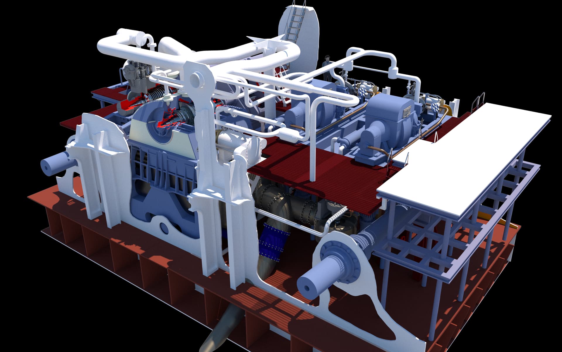
Today I finalized the upper part of the steam Turbo-generators (TG). There are two of these identical 1,2050 KVA units in each engine room. The battleship is an energy hog with every system being electrical or electro-hydraulic in nature. They both sit on their own cylindrical condensers that tap their cooling water from the main condensate system for main propulsion.
I’m happy with the results, but it was touch and go for a bit. After I finished it up I plopped it over the master drawing and WHOOPS! It was much smaller than it should be. It wasn’t just a scaling-up problem. I had to rebuild it. I’ve said it before, "Fixing an SU object is often harder than redrawing from scratch. Case in point… I started trying to reshape the frame. I ended up erasing the whole thing and building it new with the right proportions. I had to do this a couple more times.


I’ve tested the object in the slicer and it will print as a single part. With the new slicer it automatically puts supports in hidden areas that greatly increases success when printing complex objects like this one.
Next up is the large sub-frame that supports both systems. This frame straddles each condenser and then runs down to the hold deck. The frames sit on tubular legs. This part should be easier to draw than the TG… famous last words.
9 Likes
I think I’ve finalized the design on the turbogenerators (TGs) and their support systems. It was “fun” figuring out how to run the main piping below the froundation without goig through other pieces of equipment. I swear that a lot of these runs were done on site with the equipement in place. They didn’t have 3D CAD programs in 1939 to model it before cutting pipe. I am not including ALL piping, but am putting in enough to tell the story and add interest.
The TGs themselves are on the printer now and will be done later tonight. They’re intricate and delicate and I’ll be pleased if they come out okay. I will print the support system and the condensers next. Documentation on the condenser foundations are very sketchy (no pun intended), so I basically faked it from the little information I could glean from the photos. Ryan said he couldn’t criticize what I drew since he can’t tell what’s going on there either.
The auxiliary condensers are also an alloy resistent to salt water. They have their own pumps driven electrically and have their own sea chest openings through the ship’s bottom. The working floor level is obove the steel foundation supporting the pumps. The guy is actually standing on the hold floor (the 3rd skin of the triple bottom). This image was BEFORE I finalized how the condensers would be fastened to the framing.
You can see more of the piping in these overall views. The room is filling up!
Looking forward: These images show the finalized condenser suspension scheme. Still not sure if it’s correct, but until I get better info, it’s going to have to do the job.
Looking aft:
5 Likes
More great stuff Myles - thanks for sharing.
Regarding planning the route for piping , it was likely done in a model shop . My uncle ( Dad’s youngest brother) did exactly that when he worked for a company that built oil refineries.
They built large scale models of the site with the buildings and vessels in place . The proposed routes of the piping were done in wire of one small diameter. The various differing diameters of pipe were represented by discs of scale diameter that could be slid along the wire to check clearances . Interesting stuff .
1 Like
I saw this process when working for ARCO Chemical in the 80s. They were building a large capital unit and had a scale model (1:48) to plan construction and crane moves. Those models cost a fortune and modeling an entire battleship would have been a significant investment.
The turbogenerator prints are excellent. I had a minor glitch in the throttle valve and gauge panel not being physically attached to the rest of the model. I glued on one gauge panel and lost the other. I will reprint. Otherwise, I’m very comfortable with this print. Even the control wheel and relief valves rendered well.
8 Likes
After the pretty decent prints of the turbogenerators, I printed the much larger sub-frame and the support frames for the condensers. I printed the condenser with its support piping, but that was a failure. The drawing was sub-par and the supports weren’t strong enough to support the forming part. It created a crevasse that was inoperable. I bit the bullet and completely redrew the shell making sure it was fully hollow with perfecly formed walls in and out. It will be printed tomorrow.
I decided to print the new condenser barrels separately from its attached pumps and piping to simplify positioning on the printer and insure sucess.
The sub-frame needed some clean up and minor Bondic work on one corner. It also had a complete, non-complicated fracture in one of the side beams. When resin changes state from liquid to solid it creates internal stresses. Sometimes it leads to warping—although in this printer warpage has not been a problem—and, as in this case, breakage. I used Bondic to repair it, and after some mild sanding, the break is invisible. It would be invisible anyway since it will be very difficult to view.
I made the mounting holes for the legs as part of the drawing. There were some weird situations, which occurs in SketchUp, where when you intersect faces from one object to another, the lines don’t create a new surface that can be extruded by failing to create an actual surface. For these instances I drilled a small hole to guide a drill in a post-op.
Here is the repaired corner.
The top view of the sub-frame after cleaning.
And the bottom.
I positioned the TGs on the frame for this image.
Today, the leg and condenser mounting system was printed successfully. As will all printed objects, if you want a shaft and hole to fit be prepared to enlarge the hole or reduce the o.d. of the shaft. This is because the two diameters made from the same drawing would be a press, zero-clearance fit. And, due to the nature of resin printing, the shafts are a couple of thousandths (15 microns) larger and the holes are correspondingly smaller. I took one of the legs that was to fit in the holes and measured it with a drill gauge. A nice clearance was a #18 drill. I opened all the holes to this diamter.
Here’s the sub-frame on the legs. One of the legs wasn’t in full contact with the cross-beam on the drawing and printed as a separate part. i put it on after fitting the pieces into the sub-frame to insure that its alignment was correct. I fastened it with Bondic AND CA. You will notice that the arm on the relief valve is missing on the TG in the foreground. It wasn’t the only thing wrong with these prints. The steam throttle body wasn’t attached to anything being held just by the two pipes, and the gauge panel suffered from the same malady due to forgetting to draw the attachment. I printed a spacer set for the throttles and new gauge panels. I attempted to glue all this together with CA. It didn’t look very good. Then I broke off that little arm. I really liked that detail since it printed so beautifully. The result: I reprinted both of them. Once I know something this important isn’t right and I have the time and resin to do it over, I will do it over. Visitors to the ship have no idea that these machines are suspended on legs so far above the hold. Seeing this model, they will understand it.
Looking up into the supports you see the nice perforated cross-piece. This stuff was almost impossible to photograph in the 1:1 ship, that no one, and I mean no one will be able to discerne that this is either realistic or not. Modeler’s license.
I’m working on the evaporators. These are only located in ER #3. There are three heat vessels. The left end takes in seawater, boils it. It’s steam goes to the middle where is condensed with some condensate being removed and the remainder reboiled again with its steam going to the last vessel and it happens again. The output of the middle vessel produces potible water for crew, the 3rd produces feedwater for the boilers. In other words, the boilers get better water than the crew. I don’t have detailed drawings of these, and my photos only show the front faces, I don’t know where the piping goes when leaving the evaporators. I do know that the feedwater is stored in tankage in the walls of the ship immediately behind these units. Remmber, there are 20 feet of voids, tanks and armor between the engine room’s walls and the ship’s exterior.
Lastly, I’ve redrawn the growing overall project image with the new acrylic bulkheads. This is a better solution that the cutaway slivers that I was originally thinking about.
I’ve completed the print files for the floor grating. I still don’t know how many gratings I will install. They form all the working decks that separate the levels within the engine rooms. Install too many and views will be blocked, but none will give the illusion that people work on montrous machines that tower over their heads. They are supported by angle-iron frames that are very frail in 1:48 scale. I suppose I could print the grating with its supporting angle iron framing. I will see if I can old-school cobble the frames out of styrene shapes. If it’s too ridiculous I will use the printer.
I looking at that picture, I’m thinking the bulkheads could actually form the display case… Hmmm. The shafts would protrude, but that may add interest. Otherwise, you’ll have acrylic walls surrounded by more acrylic. We’lll see. Posting helps me think…
10 Likes
Another nice mini binge catch up … Superb work and skill with everything from the research to the printing to the tweaking of parts … I love that MRG … its stupidly massive with scale guy by its side … So impressive.
1 Like
Glad you’re following. The MRG is impossible to view in the flesh and capture it’s size. On the top level you’re just looking at the tops of the gear covers. In the lower level you’re looking at the flanks of the housing and it’s just looks like a gray wall, and that’s not including the 4 feet below the lower level down the hold floor where it’s all fastened. It’s also surrounded by bracing and other equipment further obscuring its mass.
Well… printing the condensers has been a bit of a challenge. Yesterday’s print failed at 47%. We were out to dinner when the printer stopped. I rebooted it and it asked if I wanted to continue the paused print. I said “Yes”, it stated printing, but when I went down to see it, the print looked like this:
And PAF film at the resin vat’s bottom.
After popping the cured resin off the film, and futher inspection, it looked like a good time to change it out. I was at 47,000 layers when the job started. Changing out the film is not hard, but it is a bit time consuming. There are two layers of screws. First to fasten the entire frame into the vat body, and then 28 smaller screws to fasten the two halves of the sealing frame together. This view shows the new film in place and the film frame fastened into the vat frame.
Here’s the screws removed to release the old film.
The new film seemed to work and I finally got a perfect print of the TG condensers. It’s the weekend so I won’t be in the shop. I will clean these up on Monday. Here they are in the draining fixture. By letting the excess resin simply drain off greatly reduces the resin loading in the alcohol wash and saves expensive resin.
I also got the sub-frame and evaporators finished designed and built the first ladder on the specifics of this particular ladder based on the ladder detail drawings I have. They’re all different and all identified. I put in a smattering of floor gratings. I’m going to print a bunch of these so I’ll be able to put them where they do the most good. The evaporators are also supported on columns just as the turbogerators are.
6 Likes
Just because it’s Saturday doesn’t mean that stuff isn’t geting done. Besides some exercising I worked on creating correctly sized and detailed ladders, started placing ladders and floor grating into perspective places. I also applied steam lines to the main condensate pump. Yesterday I added the steam lines to the turbogenerators. Gratings won’t hide too much detail, nor will the minimalist piping that I’m including. The grating supports on the lower level are pretty close to prototype. I haven’t decided how to support the upper gratings. I will have to study the drawings and photos to figure it all out.
The steam inlet to the pump has to come off the main steam pipe, but I’m really not sure how all these pipes do that. My photos are totally confusing, so I’m taking modeler’s license to put them where they make sense to me. I do know that every piece of equipment has a steam input and a discharge that has to go to a condenser. For the discharge of the pump, the only place to tie into a condenser was (I thought) would be into one of the TG condensers and ran a pipe to it.
Then…. while looking at this image and writing this post, I realized that there’s a pipe stub sticking out of the main condenser that—most likely—was actually the place where this condensate line would enter. So I re-routed the line to this stub and it makes a lot more sense. You’d be surprised how many insights I get when writing all this stuff.
Lots of things to print. I’ve started printing the piping. I have to design and print the two lubricant pumps (one electric and one steam turbine), one large and two small air ejectors that removed dissolved gases from condensate before it goes into the boilers as feedwater, and the electrical cabinets and two control panels. None of these are big or show stoppers.
7 Likes
Thanks gents!
I’m reprinting one of the TG condenser frames due to a leg breakage and the one that I had to glue on. It was time to just redo it. All it costs is some time and resin. Meanwhiile I fiddled with the opening in the condensers to accept the large exhaust flange. The hole needed to be englarged a bit so nothing had to be forced. Getting this all to fit together and stay together is not a given.
It was a gorgeous day here in Louisville topping out in the mid-70s (F) and with a slight breeze. I took advantage of this and started some of the solvent-based painting. I got the turbine rotors and MRG gears painting with Humbrel spray chrome. It’s a very nice, bright metallic paint. I also painted the bull gear. I was going to start doing all the primer painting of all the other parts now printed, but a lot of them had to be touched up with sanding and cleaning, and I was running out of time and didn’t want to rush it. I make bad mistakes when I rush. The gears look pretty good and will look even better when in the gear box. Speaking of which, I’m working on getting the main parts to fit better and preparing for the assembly screws before any painting.
I still find it hard to believe that I drew and printed those gears…
I spent the rest of the workshop time working over the piping and getting them converted for printing. I’ve also set up for printing of the “angle iron” frames that support the floor gratings. I’m printing a bunch of each type and size. I got the ladders ready for printing as well. Parts count is rising! I have to study how the upper floor gratings are supported. There is a mezanine level on the port side wall that holds all the electrical cabinets and the electrical distribution control panel. None of this is complicated, but it has a flooring frame and lots of gratings.
I’m holding off on designing the main control panel. In 1:48, my ability to do decal faces is difficult. I can produce them on clear background paper and paint the gauge faces white before application. That simplifies the process. And I just thought of it while writing the last sentence. I need Ryan to get me some good images of the panel that I can use.
9 Likes
Printing lots of stuff. Had a pipe print failure due to insufficient support strength. Will reprint with changes. Printed a gaggle of flooring frames and even more walkway gratings. When I decided to undertake this massive project, one of my main decision points was if I could print respeactable floor gratings. The new printer produced stunning gratings that eliminate the need to create these kinds of things using photoetched. They are ephemeral and very fragile, but when glued to the floor frames they will hold up nicely. I finished the turbogerator condensers with most of their piping. On the printer right now are all the ladders needed in this space. There are five different varieties.
First the condensers.
I pre-located the drill holes in the drawings and subsequent printings, so the holes just had to be opened up to 1/16". A piece of 1**/**16" brass tubing made a very secure connection with CA adhesive.
Here are the condensers with all minus two pipes.
I printed a bunch of single and double floor frames. There’s one leg that I designed without enough integration and it’s not very strong. I reinforced its interior with Bondic making it more secure.
I also have a ton of worthy floor gratings. Took close to an hour to carefully separate them from their support system. This new printer will reproduce just about anything.
Some of the bars are damaged on the edges, but they’re bigger than the frames. When trimmed they loo pretty darn good if I do say so myself. When painted oxide red they will be great.
And they look great (no pun intended) from above being almost transparent due to the thin bars.
I’m designing the lube pumps. There are two: one electric powered that was installed in the 1980s refit, and the other steam turbine driven that appears to be the original design. When I dropped their foundations into the master drawing, I was concered that there seemed to be no room to move around them. I remember walking next to the pumps with lots of room. Did I make a scaling error?
Nope!
Based on this analysis, the configuration of the equipment in ER #2—the one open to the public—and ER #3 shows very little clearance around the pumps in the one I’m doing. It’s the position of the MRG in #2 driving an outboard properller shaft #4 and ER#3 driving an inboard shaft #2. Shafts are numnbered from startboard to port, whereas engine rooms are numbered from fore to aft. The drawing tells the story. Notice that the ladder to the upper lever is very tightly fitted, versus the wide-open-spaces in ER#2.
In this picture that Er#2 roominss is on full display. That space does not exist in ER #3. That old dude walking is me…
So I will be trued to the plans a shoehorn the pumps into their repestive spaces. Onward and upward.
7 Likes
The ladders came out as nice as the gratings did… maybe better. Here’s some pictures that show. The stair railings are only 0.020" or about 1 scale inch. Actually scale! By not curing the resin more than 3 minutes and with my resin blend, the railings still have a lot of sprint to them. You can bump them without breakage.
Below: this was before I did some very delicate sanding to remove the slight support nubs that remained.
This is the five step stair.
And I threw some grating next to the tgs just to see how it looked.
Gratings was one of the things I thought about when I decided to build this ridiculous project.
I’m continuing work on the lube pumps. Don’t have any good drawings of these so I’m working only from photos. Electric pump is one the left and steam turbine pump on right. Steam pump is OEM from 1943. Electric was swapped in 1980s refit. Steam piping is complex and I’m trying to interpret. Couldn’t get close to them in ER #3. Work platform grating is where the legs top out. The legs rest on the 3rd bottom (hold floor). Still have to fit them between the main reduction gear supports. Probably will need to modify.
This is what I’m talking about… it would be a bit easier if it wasn’t for all the insulation.
8 Likes
Those gratings are amazing, what a cool development!
Thank you. It kinda blows me away too.
I’m just about finished designing the main air extactor. The first thing I had to do was learn what an air extractor is and why is it there. There are three of these in the engine room; a large Main Air Extractor (MAE) and two auxiliary air extractors. The main is pulling vacuum from the main condenser and the auxiliaries are pulling vacuum from the turbogenerators condensers. They look the same except for their size. For steam turbines to function effectively, the exhaust steam must be drawn out of the machine into vacuum. The steam is depleted to a point where it would lose all forward momentum without the vacuum. There is some negative pressure created just by condensing the volume of steam to water in the condenser, but it’s not enough since there is leakage in the system.
The main air extractor works on Benoulli’s principle that pressure on a surface is reduced inversely proportional to the speed of a gas over the surface. 600psi steam is applied to a venturi where the suction line is attached to the gases in the condenser further reducing its internal pressure. Very high vacuums can be drawn this way. The MAE outputs the extracted air to atmosphere and any condensed feedwater is fed back to the main condenser hot well. Further feedwater prep is done in the firerooms and is not part of the model. There is also condenser coolant water in and out that is used in the internal condensers in the MAE. It’s really a complicated piece of equipment.
I am totally guessing exactly where the piping goes for this thing. Here’s the a picture showing why that is.
Given that, here’s a rendering showing it in place on the upper level. I don’t have any detailed drawings about the MAE or its foundation. I have four images inclduing these two.
I’ve got requests into Ryan asking for more information about this. Regardless, I’ll do something respectable.
I printed the lube hand wheels separately and applied them with 0.025" phos-bronze wire. Look much better than the partially deforemed ones that were printed on the part.
I removed all the tall angle supports from the MRG frame to accept the smaller version that is now printed integral with the Lube Pumps. After prepaing the surfaces I used the rubber-infused CA to adhere the electic lube pump. The modified (fixed) steam lube pump will be printed along with the MAE today or tomorrow. The electric motor came out beautifully with the cooling ribs perfectly defined.
While the steam pump print has some errors there were some spectacular print features that blew me away! This is an extreme closeup of a spring that I downloaded from the SketchUp 3D Warehouse. I reduced its size, but did nothing else to it when I determined it was printable. It has some loops at the end.
Here it is on the pump.
And if you look closely, the printer reproduced those loops. This isn’t supposed to happen… or at least it didn’t happen with previous versions of the LCD resin printers. With the naked eye, those parts are tiny. They’re 0.010" or less.
I printed more ladders. I found that the short ones were also with full treads and I needed a ladder with 9 rungs.
Getting good at making ladders. Till next time…
9 Likes
I got the aux air ejectors designed, but they’re kind of fictional. I have no drawings of them nor do images help very much. Here’s an image that “shows” the two aux air ejectors that produce vacuum for the turbo-generators. Can you see an air ejector hiding in that piping? I can’t. Therefore; I just shrunk the main ejector until it made a resonable size. Anyone visiting the engine rooms probably won’t see much of them either. They are on the right side of the image.
I have the foundation drawings for the aux units. They are brackets that attach to the bulkhead wall with stiffening on the fire room #4 side. I drew them sort of correctly, albeit simpilified. That said, I don’t have any drawing of the units themselves or the foundation of the main air ejctor. If it goes straight down to the 3rd skin like some of the heavier gear does, it won’t work becasue they would pass through the end bell of the main condenser. I chose to bracket it also.
Here are the two unpiped aux air ejectors. They are fatter than the real ones.
I’m running into a jam trying to get the clear acrylic bulkheads laser cut within a budget I can tolerate. I’m donating this model like the other two, and spending the best part of a year in its creation. As a result, I’m trying to mitigate out-of-pocket expenses as much as I can. That leads us to plan B; back to hand-cut styrene sheet. I’ve already bought the sheets for this eventuality and will make the end bulkheads and all the under-floor framing out of styrene. Styrene is much easier to glue togther (silver lining).
I’m calling this approach, “the Swiss Cheese cutaway method”. The stiffeners on the fire room sides will add structural integrity to make the bulkheds work. There would be part of the boiler supports on the other side. Stiffeners are mentioned on the plans.
Here’s the fore bulkhead:
And the aft bulkhead. It’s important that they support the propshaft pass thrus. The tongue sticking up is supporting the entry ladder. I think I’m going to make a bit of ceiling there to model the entry hatch into the engine room. It’s an important feature. There’s also a small hatch in the fore bulkhead to enter the #3 fire room.
I printed out full-size plans for all the styrene parts in prep to handcut them. I’m still waiting for another quote for laser cutting acrylic, but I’m not very optimistic about the outcome. I still have to design the control panels and electrical cabinets. After that paint and assembly will begin.
4 Likes
I’ve piped the aux air ejectors. This is not prototypical, but it’s reasonably functional. This is just the primary lines. I’m not attempting to include any secondary lines. I may attempt to print this as a complete assembly… would help in alignment. Ryan gave his approval on the “Swiss Cheese” approach. I will have a lot of styrene cutting to do.
5 Likes
While still doing more design, I started on the styrene parts. I printed full-size plans for all of the parts using PostRazr to help convert bigger-than-letter-sized drawings to mulitple page prints since my version of CorelDraw doesn’t play well with the latest version of Mac OS. I’d have to pay another $300 to upgrade CorelDraw… which I’m not going to do. You export the big drawing as PNG to PostRazr (free online app) then it converts it to a tiled PDF output that can be printed in mutiple, overlapping pages by Adobe Reader. Convuluted, but free.
I started cutting the pieces with the front bulkhead. Maybe I should have started with some of inner pieces to perfect the cutting… nope. I used the Lord Nelson method, “I went straight at em’”. Might have been a mistake. I mis-drilled one of the lightening holes in the lower frame portion. This will show!
I cut the holes for the prop shaft seals. These go in at an angle so a little siop in the fit is tolerable. To cut these I used my dividers-with-a-chisel-blade method, where I just twirl it around and score the plastic. I cut radial slots to the center and break out the piece leaving a reasonably-sized hole. Some light Dremel sanding work cleaned up rough edges. The shaft seals fit okay.
I used the same method for the steam pipe opening at the top. For the oval hole for the condenser inlet scoop I used the "drill-a-zillion-little-holes-around-the-perimeter method and used a #11 blade to cut between them, breaking out the center. Again, Dremel sanding finished it up. I chose to drill all the rest of the holes and radii. I didn’t have a plastic-ground drill of the right size so i had to grind one. I have a commercial plastic bit that I used as a guide. To drill soft plastic like styrene you need a sharper point angle. Standard drills are 118º and need to be something around 90º. Also the drills need less rake angle under the cutting lip. If you don’t do these things, the drills will tear and grab the plastic creating more of a mess than a hole. The grind worked.
I used a small pilot drill to locate the centers of the frame holes and drilled them all successfully except for the hole 3rd from the right in the picture. I am really annoyed by this! I so annoyed that I may plug it and re-drill. I’ll think about it. For all the rest of the holes in all the frames, I’m going to temporarily glue them together and drill as a batch including the back bulkhead. I’m also going to drill the upper end of the cross-lap slots instead of working about cutting a square edge. it won’t matter.
To cut the remaining free-form shapes i’m thinking about using a jig or jewelers saw. I did the first cuts by scribing with a #11 blade and breaking out the pieces, but occasionally the knife slipped and cut into good stock that will leave a mark requiring post-finishing. Using the saw would be more controllaable and leave smoother edges.
Meanwhile, I’m about to finish the last drawing challeges, including all the electrical, control panels and diamond plate flooring for the lower level. The diamond plate I drew for the 5" proiject, while scale-sized was too fine to see well in 1:48. I’m going to enlarge the bumps a bit and then print.
The complex nature of the project at this point is mind-blowing, even for me, and I’m the guy doing all the drawing. Notice the large column in the center of the image. That’s a prominent feature in the ER. It required me to change the routing of the main steam pipe to clear it. Also note that the upper mezanine platform is ready to receive the electrical equipment after I draw it.
All of the platforms and catwalks will require handrails before they’re fully done. I’m probably going to make them out of soldered phos-bronze wire to reduce opportunities for breakage. I’m still working out how all the floor panels will be supported, especially since there’s not a full bulkhead in the fore or aft from which to hang them.
6 Likes
I tried using the jewelers saw, but it wasn’t worth the trouble. Went back and did it by scoring the lines and snapping. Took my time and the results were good. I cleaned up the holes and curves with the Dremel with the smaller sanding drum, and did deburring and it’s ready for the slotting. I’m going to slot all the frames glued together so regardless of their specific precision to holding the lines, they will all be equal. I cut one mid-frame out of the 0.040" sheet, but stopped at that one. I was concerned about running out of the thicker stock for the rear bulkhead. I can get away with the 0.030" stock for the cross-frames.
I attached the Aft BH to the styrene and began cutting it out. This image shows closeup of how to do a scored diameter hole in styrene. After scoring with multiple passes with the dividiers, I scribed cross-line all the way through which provides a place to grab with some pliers to snap out the pieces. The hole requires a little sanding drum work to clean up the edges and do final fit on the shaft seal.
The print of the Main Air Extractor came out beautifully. The pictue shows two of them. I only need one. One is a better than other slightly, and I’ll use that and put the other in the surplus pile.
In the same run I printed the four remaining tubes from the TG condenser to the heat exchanger. There were two on each TG and are slightly different. The valve bodies and their handles came out really nicely.
I re-drew and improved the diamond plate I used for the 5". This was originally downloaded from the SketchUp 3D Warehouse. The original size of bumps was too big for 1:48 and I shrunk them. For this application I shrunk them a bit too small. That said, the orginal artist didn’t group or convert the bumps to Components. With SU Components, if I change the configuration of one bump, all of the bumps change regardless of where they are or how many plates were drawn. I’m printing the flooring in 2’ X 4’ pieces. I made them pretty thin and adding some cross reinforcement to help mitigate warping. I’m printing out 20 of them and it’s going on the Machine tomorrow.
2 Likes
The Steam powered lube pump printed correctly this time, but I broke a pipe in cleanup. Picture will come after I fix it. I also got good prints on the aux air ejectors and the 9 step ladder needed for the entry stairs that come down from Broadway into the engine room.
I got the aft bulkhead and finished up ready for drilling. Unlike the fore BH, I held off drilling this and waited until all the frames so I could temporarily glue them all togther. Using the #11 to scribe all the curves really worked out well in the end. Had to change blades frequently.
I then cut the individual frames out. I used MicroMark pressure sensitive adhesive.to temporarily hold the patterns to the styrene. Occasionally, some cement stayed behind that was easily removed with Goo Gone.
I did not drill or slot any of them.
I then temporarily glued the stack to the aft BH in readiness for drilling all at the same time.
Before gluing the stack to the BH, I clamped them together and trued up the ends so they were all the same size on the 1" belt sander. I used little dolleps of Testor’s tube cement to hold the stack together. The holes were located on the BH with a smalll 1/16" drill that will center the big drill. I wish I hadn’t drilled the first BH yesterday. After I drill these, I will cut out the cross frames and do the same thing to them. I will cut all the slots while the frames are still stacked guarenteeing that all them are in the same place. Actually, since the floors will cover all but the outer edges of all this framing, I really don’t need to include all the cross-frames. I probaly will use them because, I’m a) going to cut them anyway, and b) the entire model is being fastened to this floor (as in the real ship) and having it solid and stable will not hurt. It will not, however, have to protect against topedo attack.
Started drawing the electrical equipment on the upper mezzanine deck. I finished the lighting tranformers that have louvered surfaces. Had to figure a way to draw reasonable louvers and think I got it.
I’m now drawing the electrical console. I have a good image of it, but not it’s sizes.
8 Likes