JLTV UTL M1278 and an RG-33 SOCOM AUV Build Conversion

As real work is slow, well, a guy can spend some time in the fab shop, working on this!

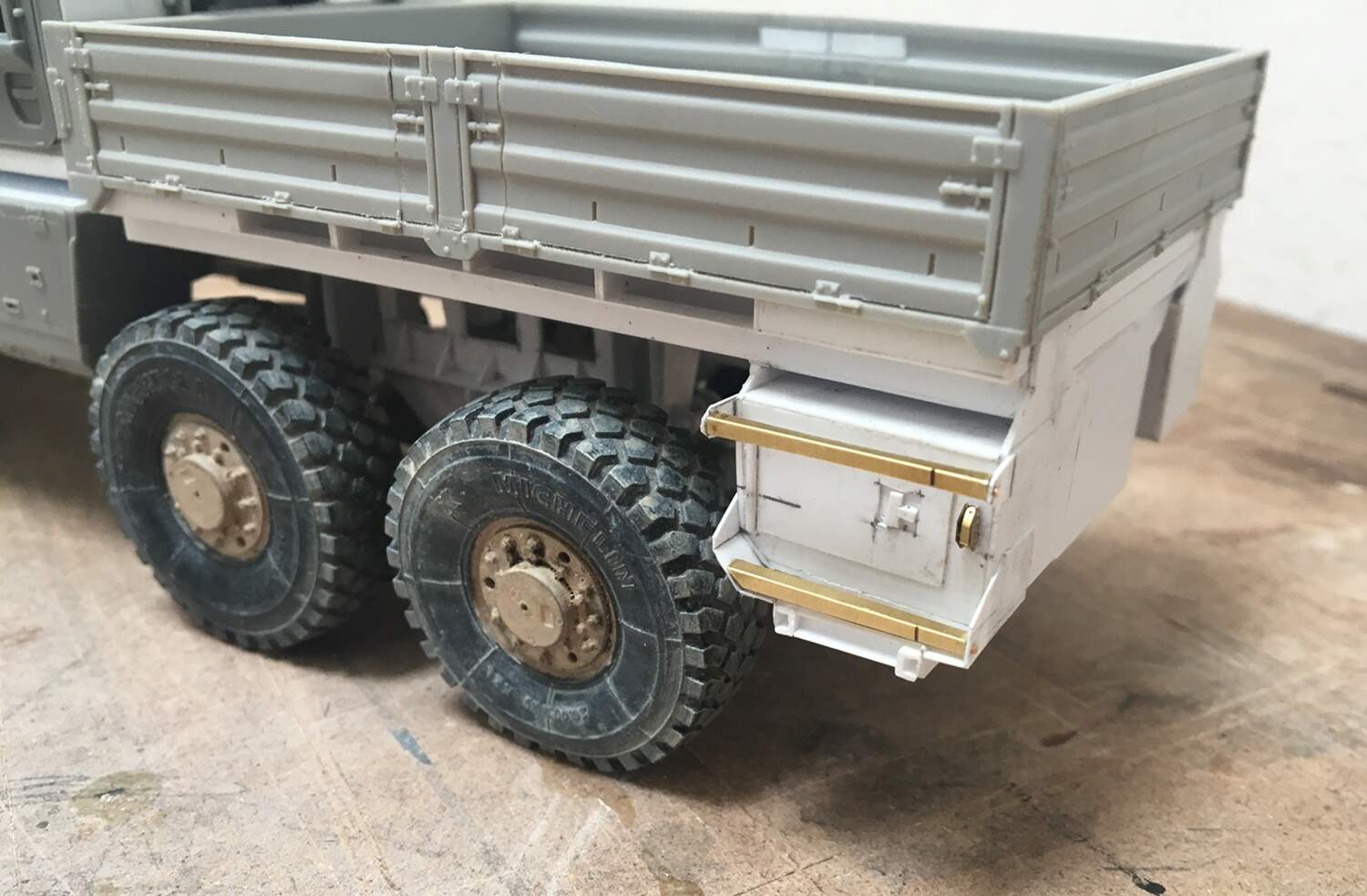
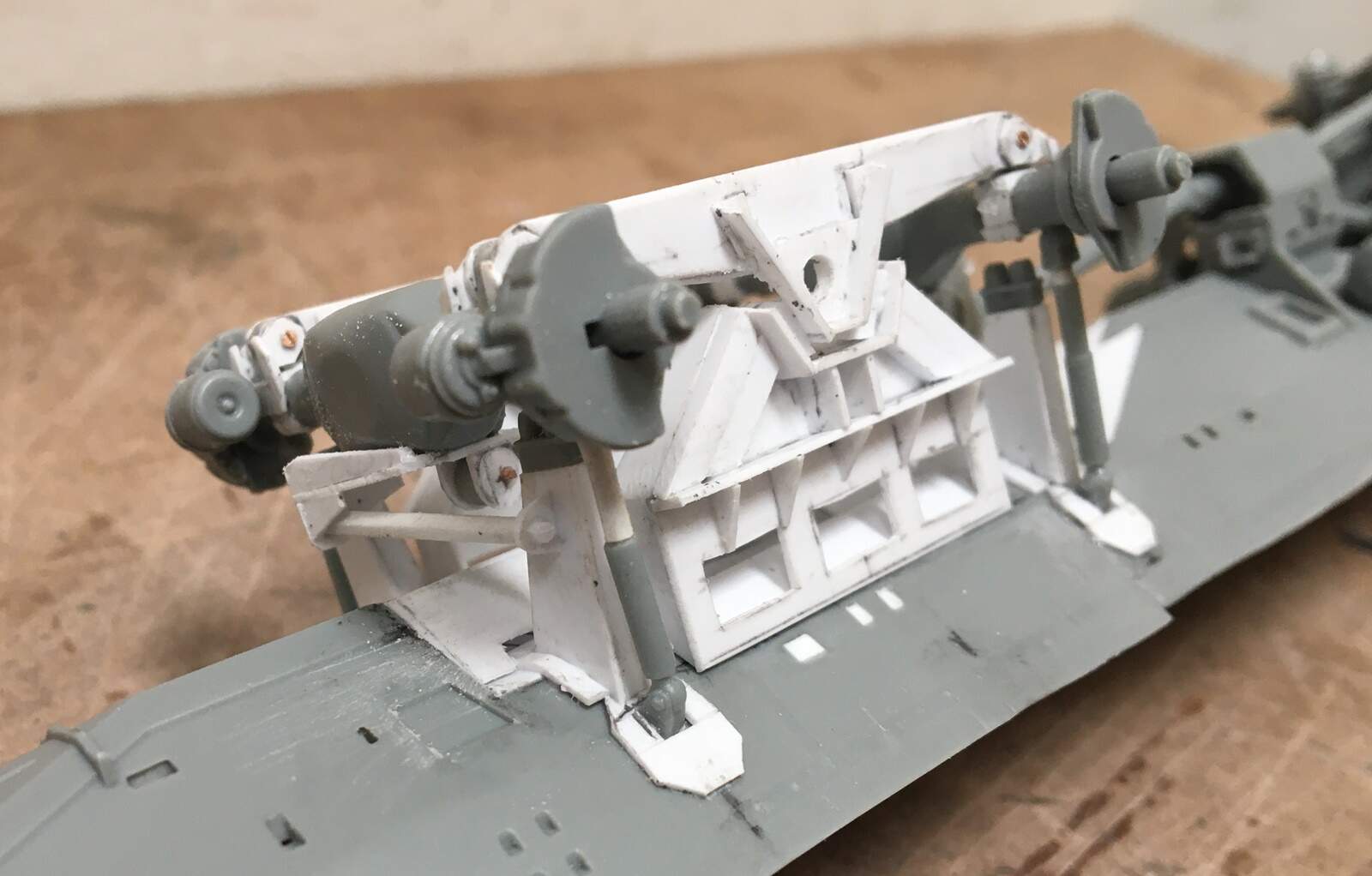
That rear end, is no picnic to scratch build. I am glad to have used that jig, as I kept it in place for a relatively long time during this process, and the results are pretty good - specifically, it sits level and the parts are square - I had doubts about achieving both.

On we go:

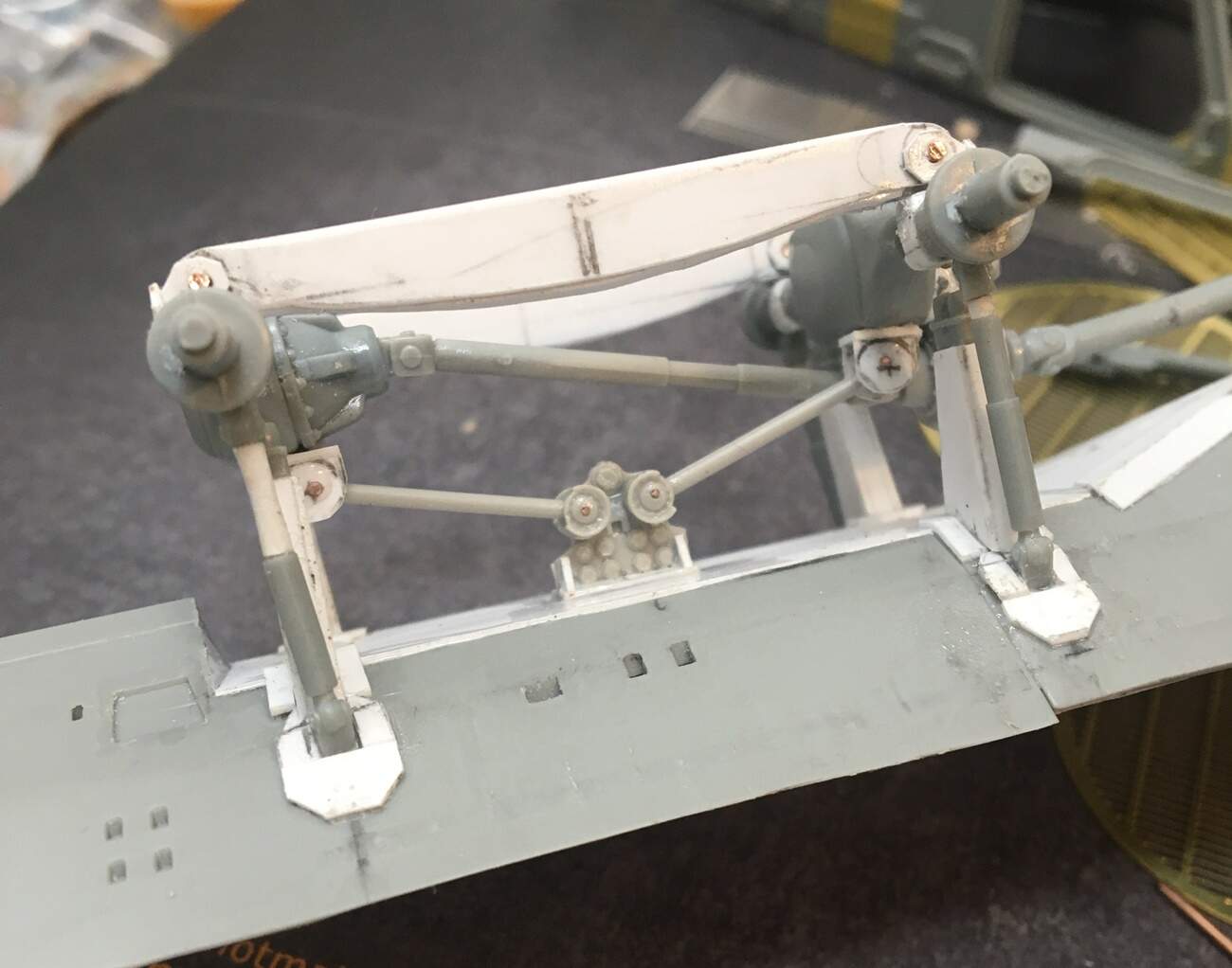
It turns out the shocks from the kit were just a bit short, so I extended them, and, added metal pins to the top and bottom - which allowed me to plug them into the hull and axles. This worked pretty well, to help keep things squared up and where I wanted them to be.

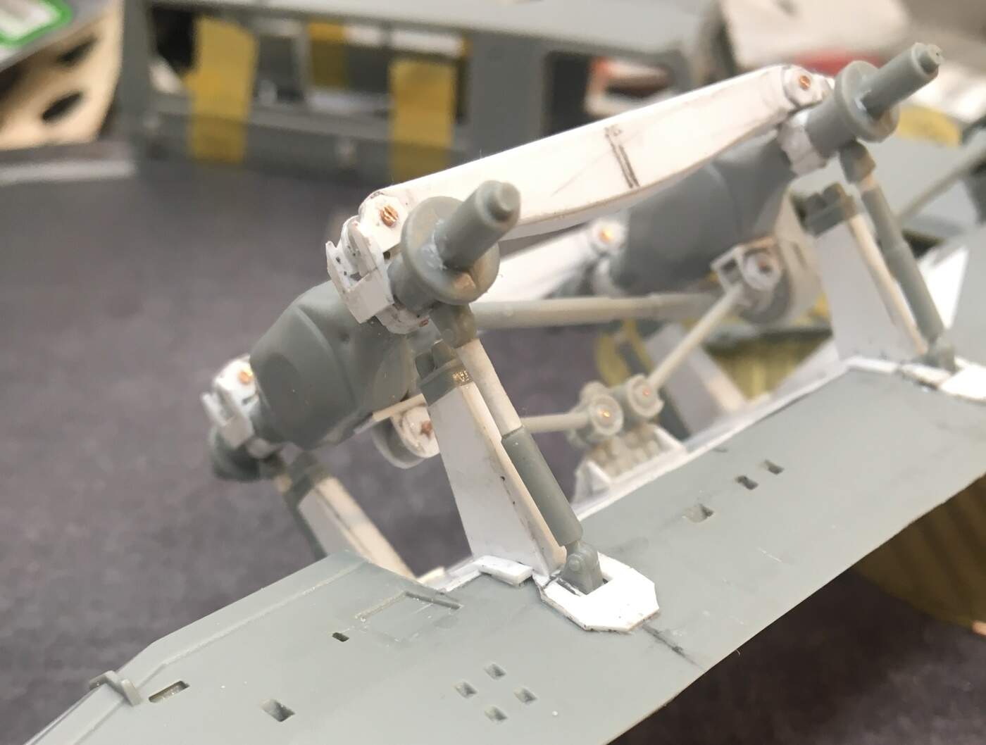
The torque arms are from the M1083. I also used pins to hold these in place - which allowed me to first glue down the central mounting plate, then I could freely tilt the arms to sit on the axles - they were then flooded with glue! Next up were those bump stops. This was a bit harrowing - as they are mounted on small towers that have a sloping base and taper inward from the hull… :sweat: Despite their being firmly attached to the hull, they don’t touch the axle, so don’t help with stability.

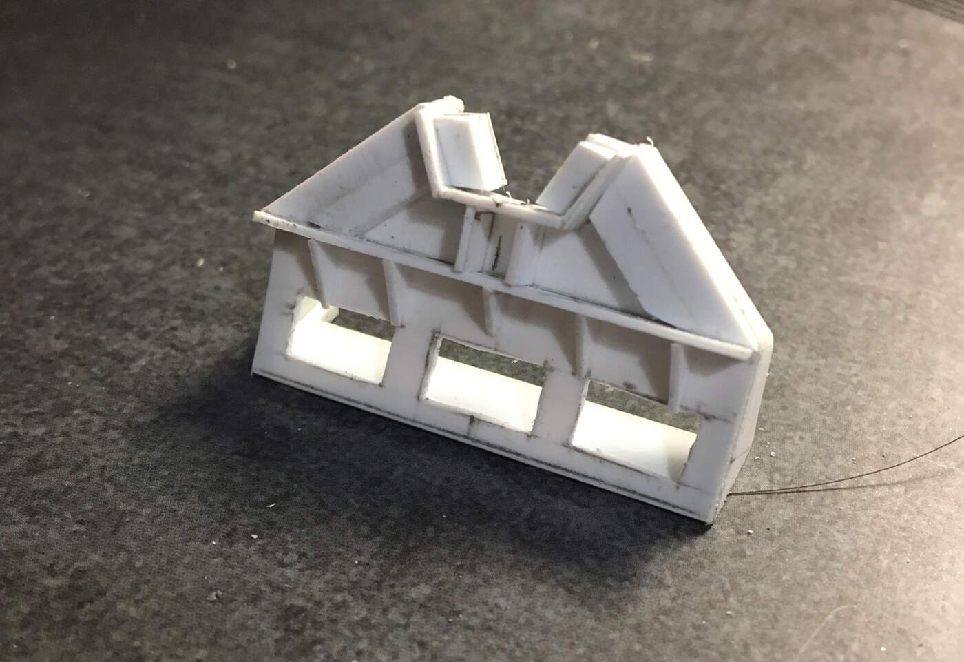
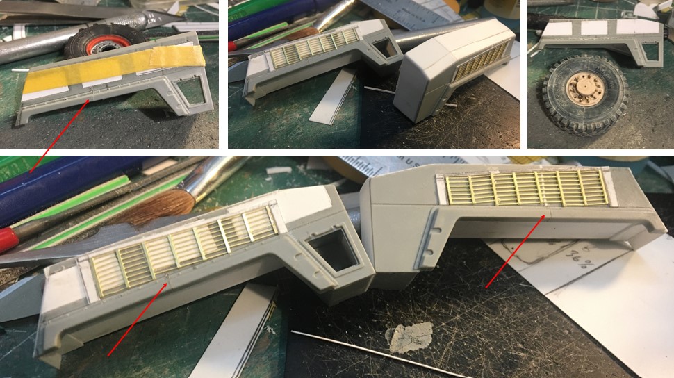
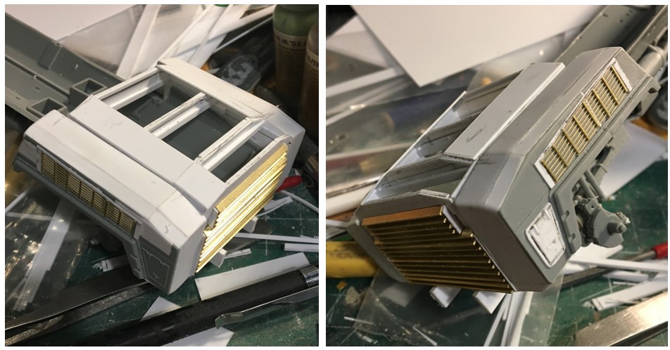
I won’t recite all that’s going on here - the key element is the structural frames for the suspension.

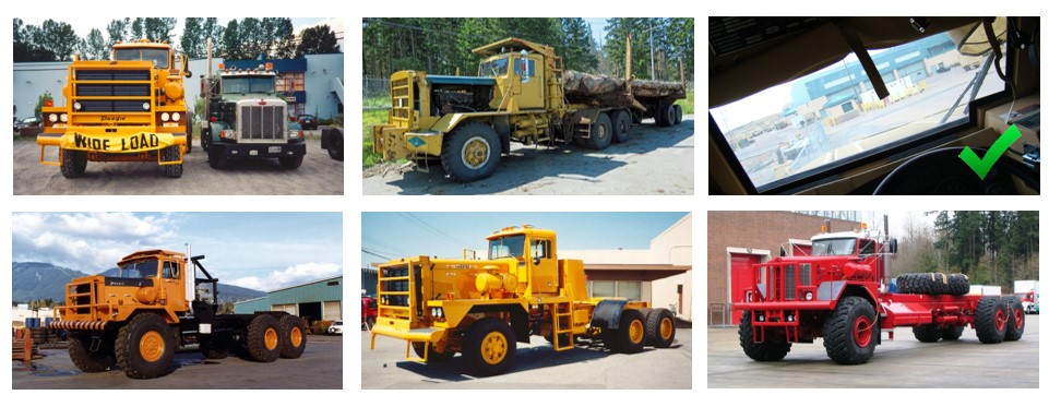
While Rob’s photos don’t have dimensions for this there are several very clear pictures of what they looks like, and one straight-on shot that shows enough that I was able to trace off the spacing between the parts shown in the photo, and establish some proportions and not to scale dimensions.

Then establish a few key dimensions on my build and determine percentages of distance, to allocate spacing relative to the photos. While a bit tedious, it worked fine.

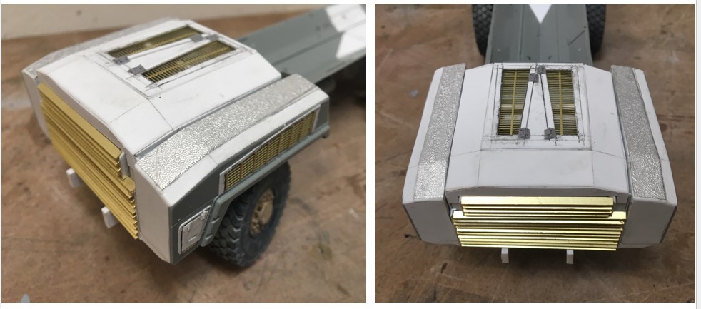
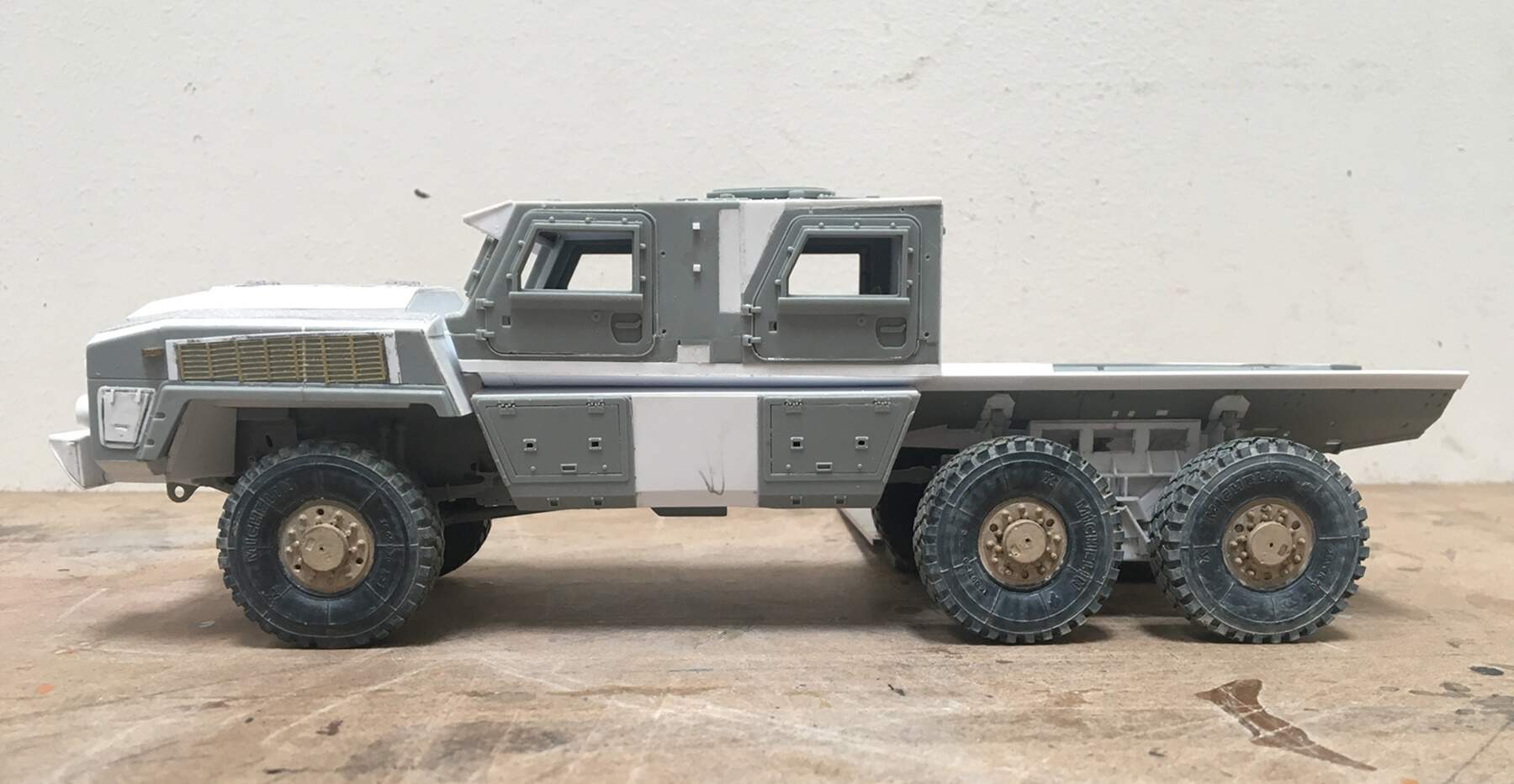
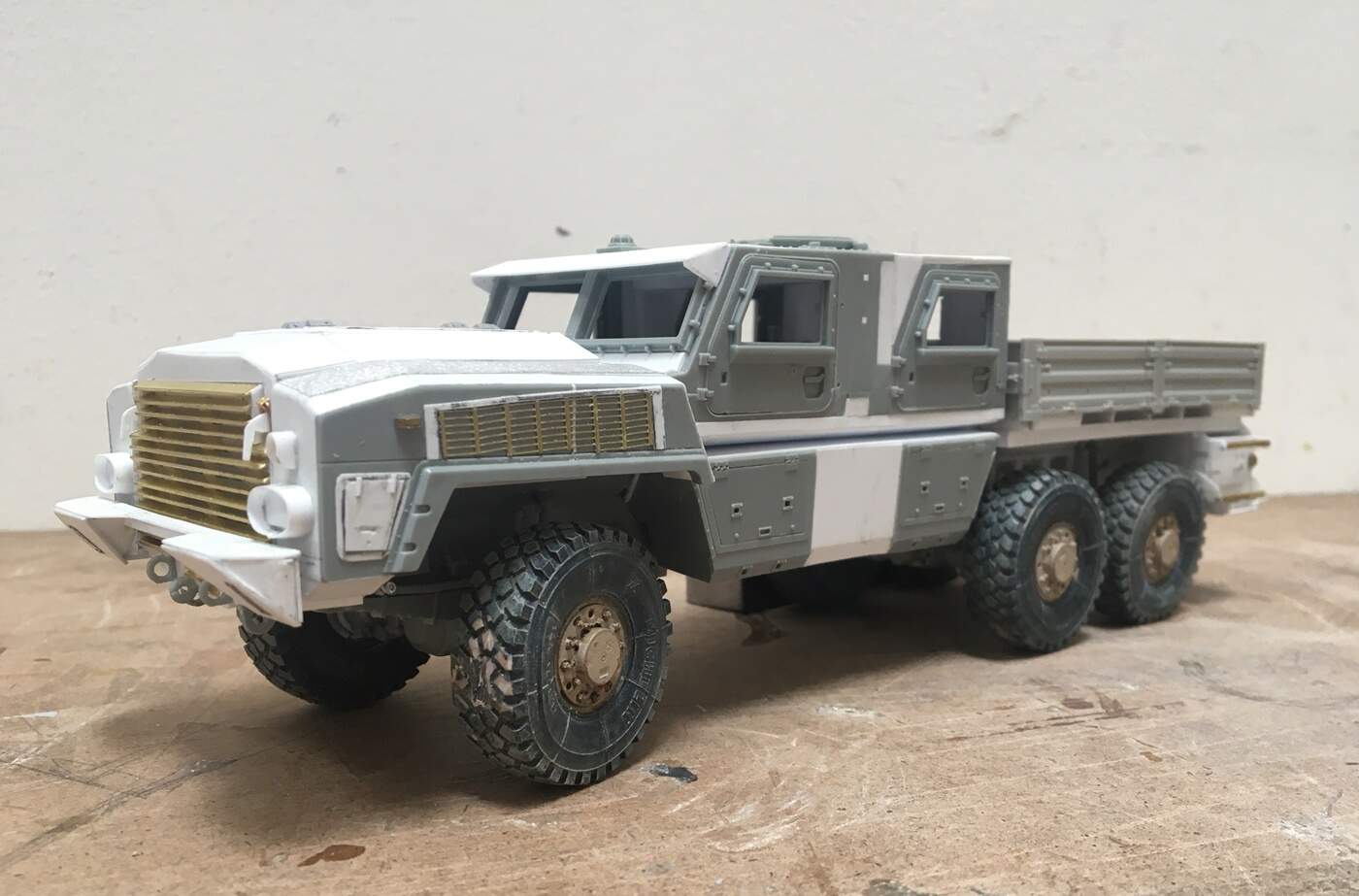
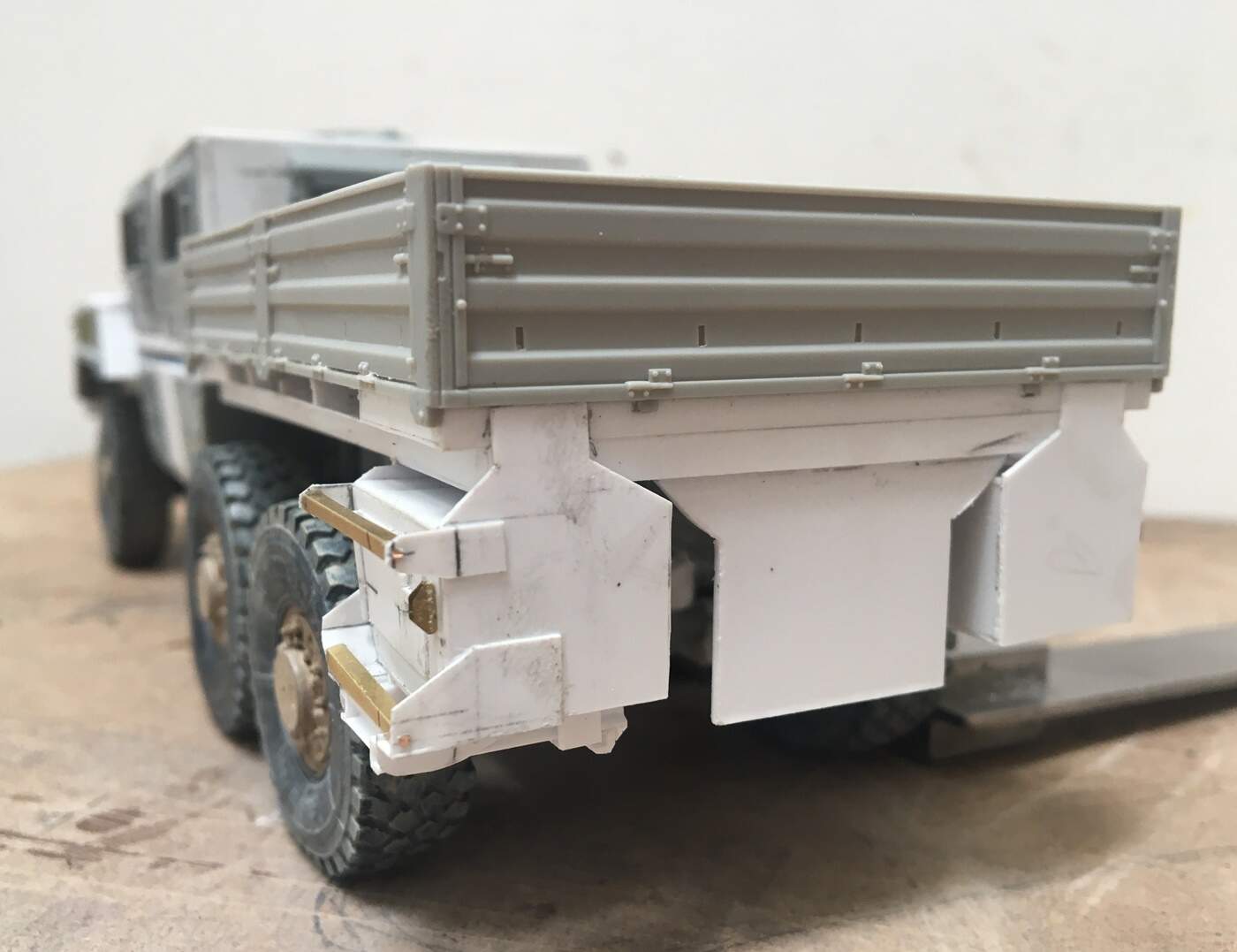
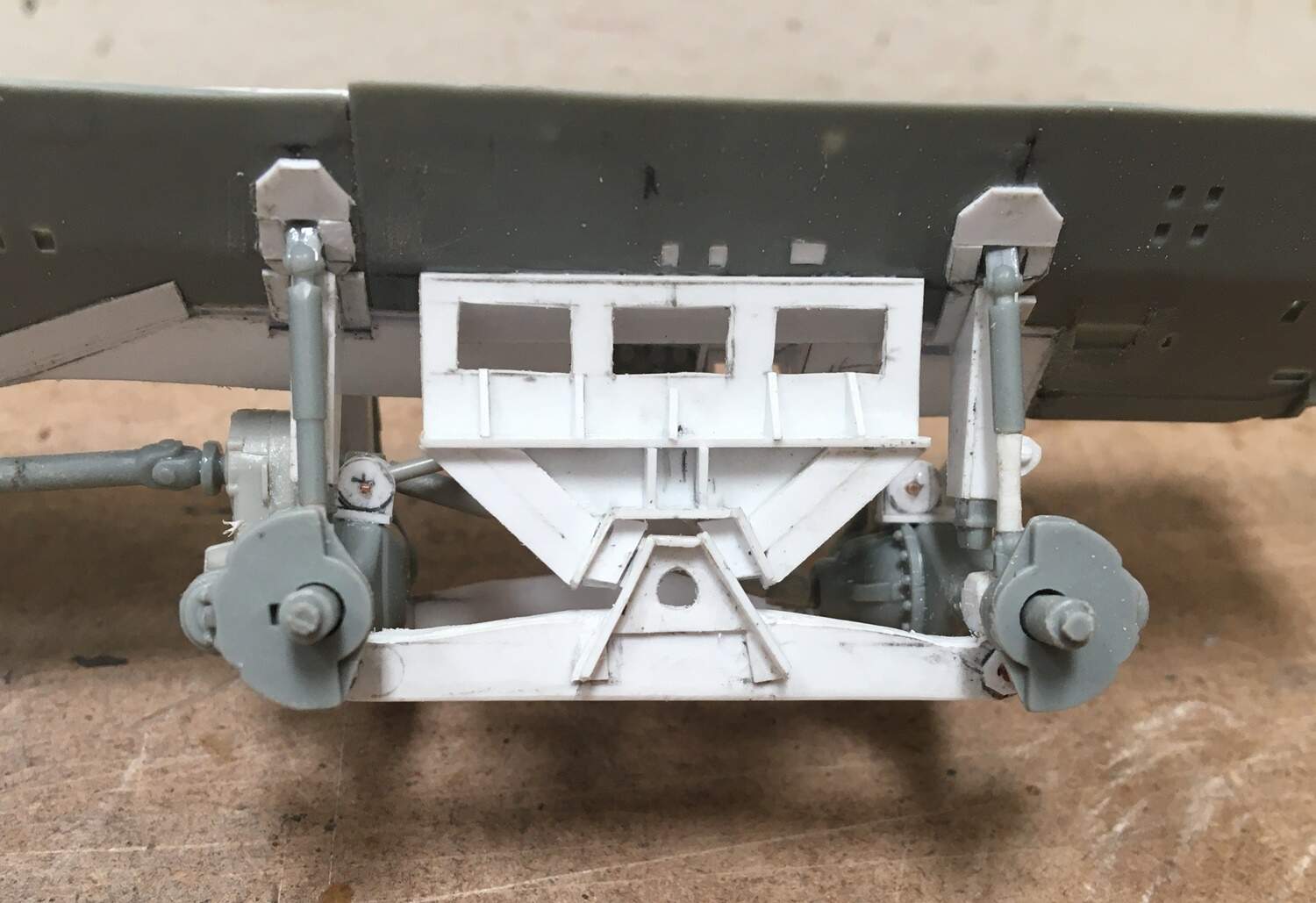
Next - I concluded that while I needed to cut the hull to get my axles to fit, I couldn’t live with the resulting flat spot, so, when this was all done, I went ahead and added the hull shape back, albeit slightly lower than the rest - in the parlance of design review, I think it demonstrates convincing realism! Unhappily, there isn’t much contrast in the photo, so you’ll have to take my word for it, there is indeed a “V” shaped hull in there!

And guess what? nobody will ever notice! :smile:

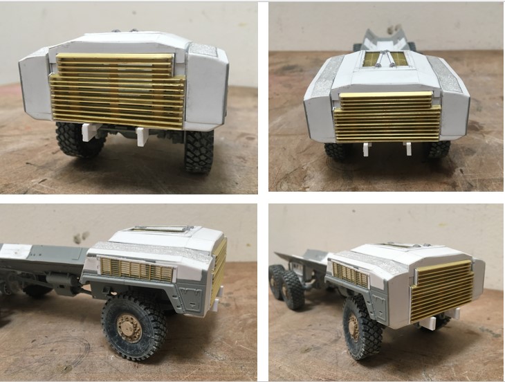
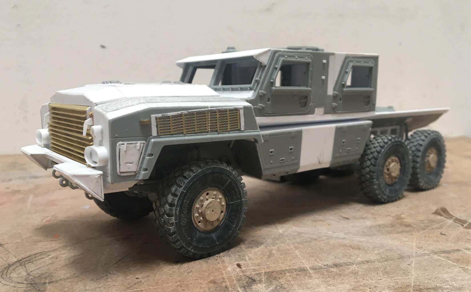
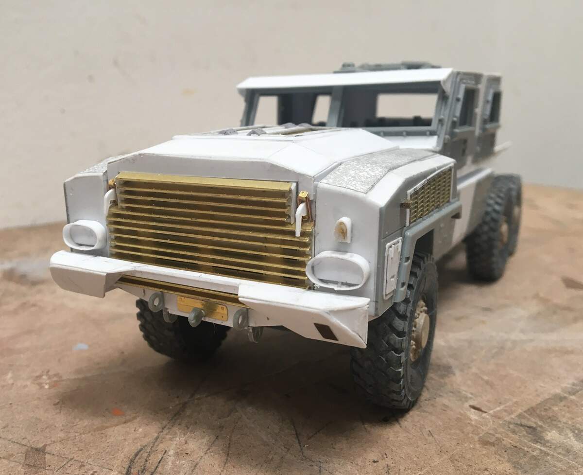
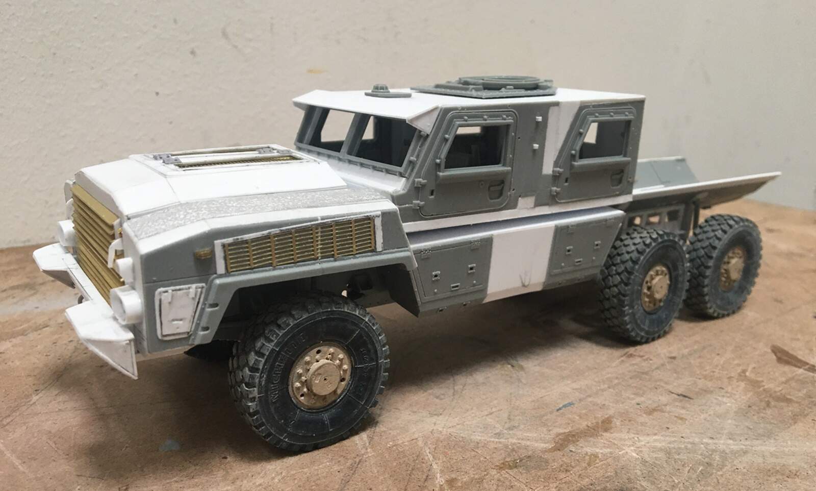
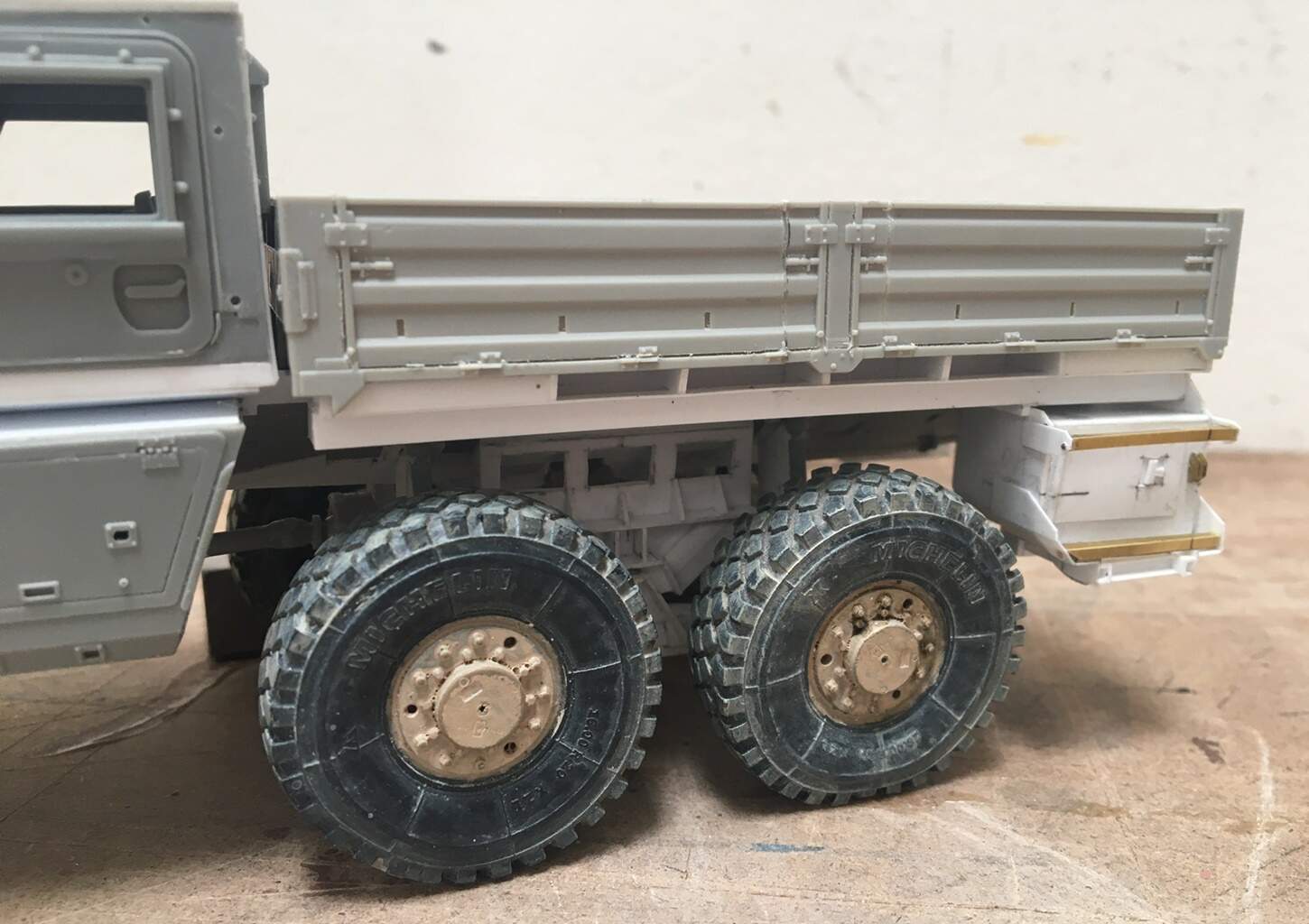
As for the truck right now:

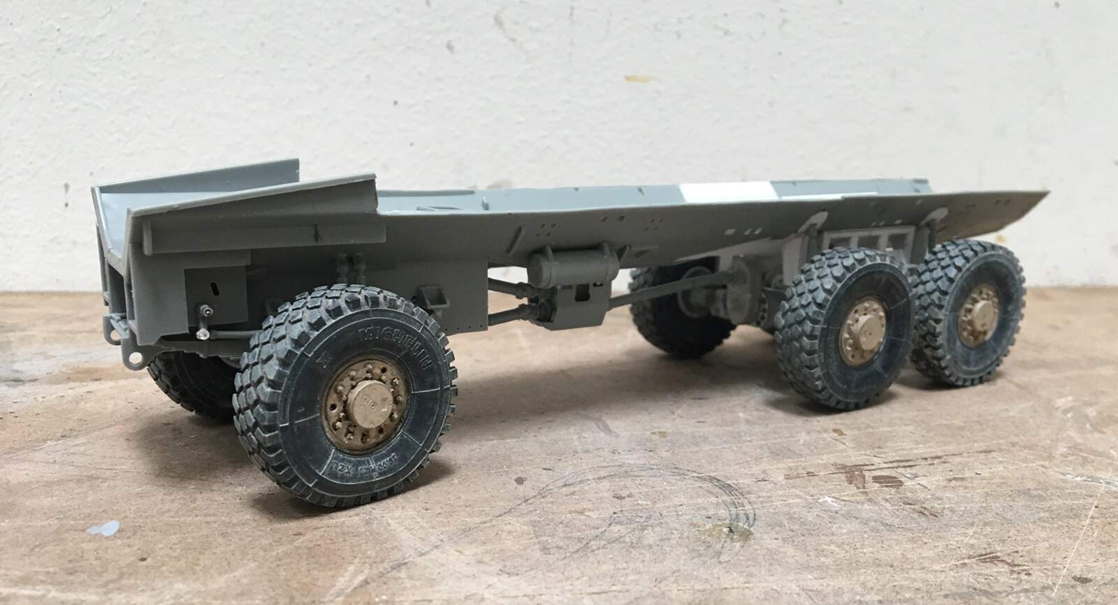
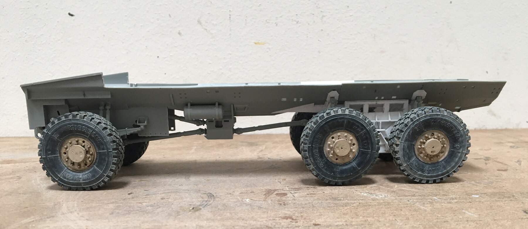
In the lower picture, you can just see where I added the “V” hull - lol- again, not all that obvious - which I suppose is good news - the better news: This sits level and is pretty solid.

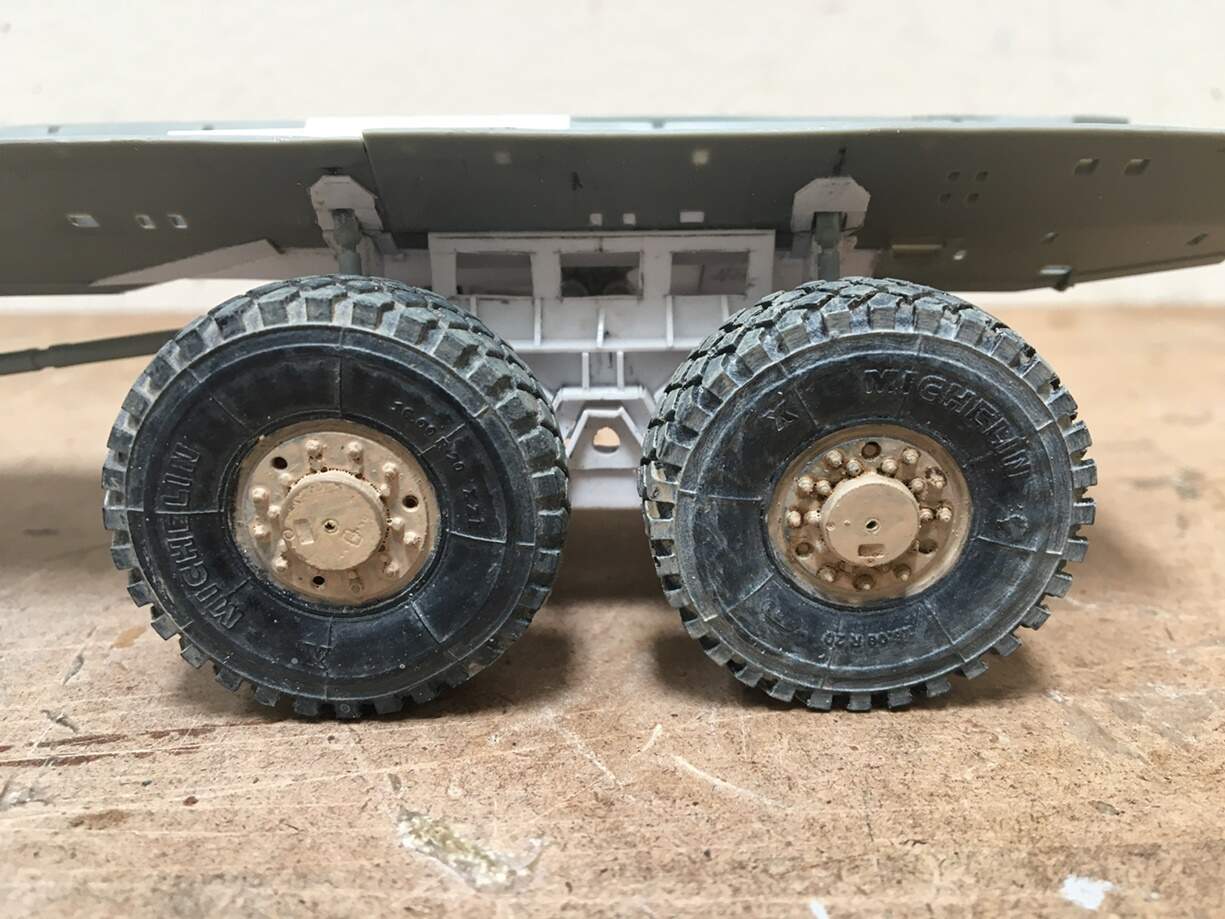
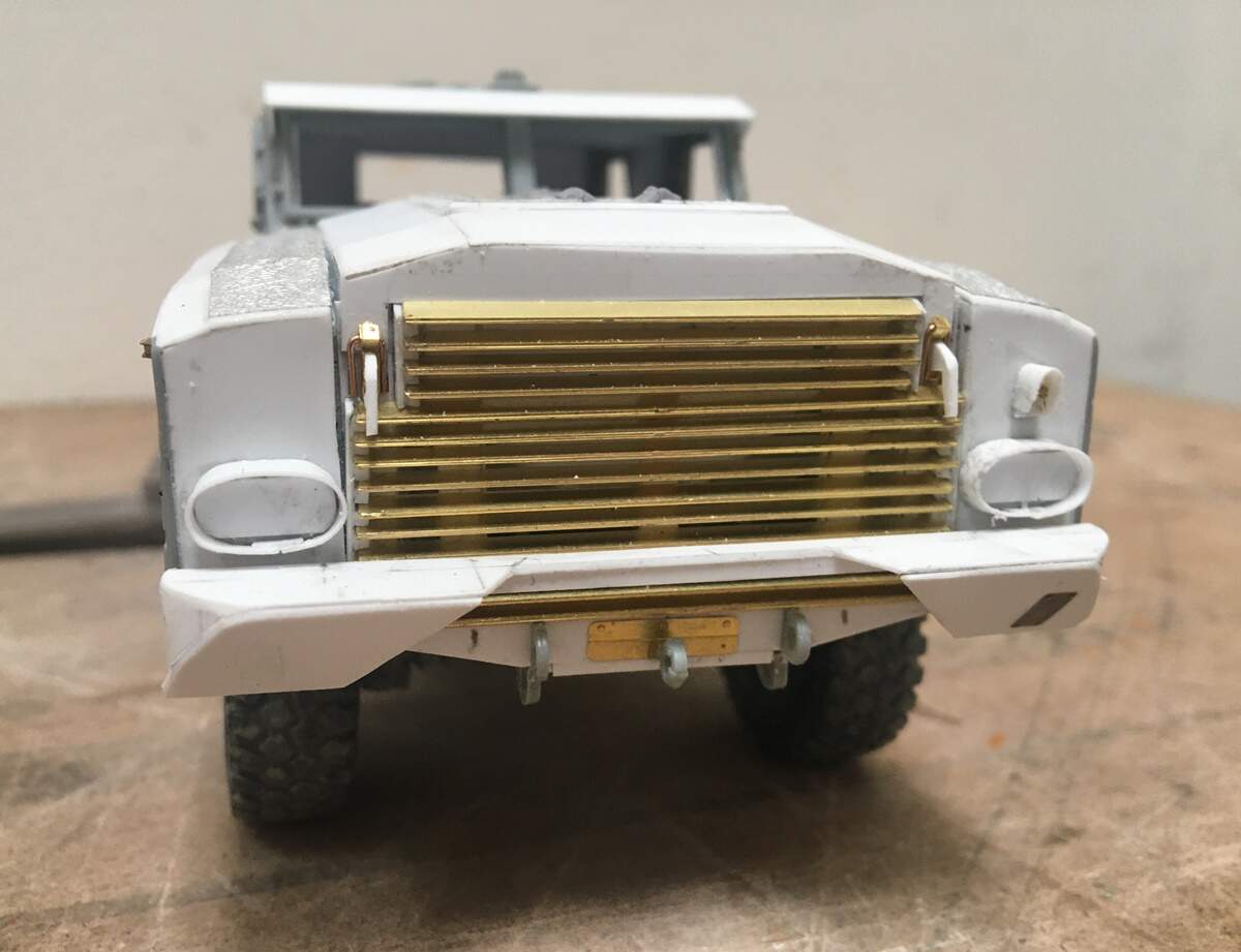
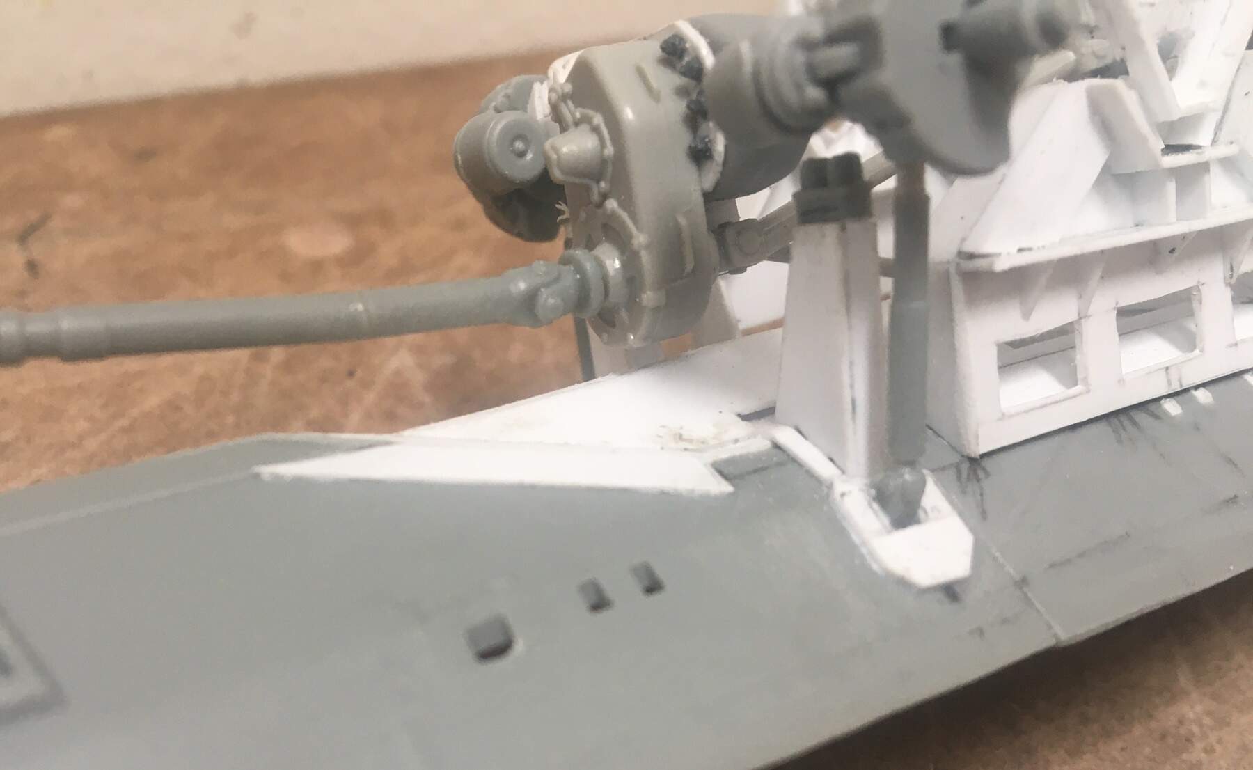
This needs some cleanup and bolt heads - they are apparently on their way in the form of some hex rod.

Next up, I’m trying to decide - cab or hood?? likely the hood -

Thanks for having a look -

Cheers
Nick

10 Likes

Wow; that’s impressive fabrication work, Nick. Keep up the excellent work. :+1:

2 Likes

You are definitely Konversion King!

2 Likes

Hi model builders,

As real work has remained a bit slow, well, on with the model I’ve gone. I’ve spent the last few days working on the front end. It’s not done, but I have made progress - first up, the front fenders:

So, the plan includes the use of two front fenders from the RG31 to make one for the RG33. The red lines with arrows show where the splice occurs. They underwent several additional changes to meet my needs - the basic facade is about the same, but the structure and overall form is new.

In addition to being merged, the top of the fenders were cut off, following the top of the yellow tape line, shown in the picture on the upper left. This area was then rebuilt, with new backing, and the two-fold top, and eventually fronts and backs added.

While not perfect, I am basically pleased with the louvers. I considered cutting the back out and adding in some screen, but that was not practical because what you can’t see behind is a series of added styrene brackets used to support the top pieces of the fender - cutting an opening wasn’t worth it.

Next up was the giant hood and grill - this front clip is a monster:

Like the fenders, the hood includes multiple sloping surfaces. As such, I built some internal ribs, which allow panels to be laid down matching the various slopes. Then came the hood:

Two large, tapering, and hinged vents are located in the hood. This is layers of styrene, etch and resin hinges - still more to add, but it is getting there.

I’m not too worried about being able to see the middle rib - meh - it’s fine. I might add in something that vaguely looks like an engine - just to fill the volume - not decided just yet.

The silver material on the top of the fenders is the foil wrap from the top of a San Pelligrino can, which looks a lot like the anti-slip surface used on the real deal.

This is a bit out of sequence, as I built the grill before the hood, but didn’t take any WIP images which is too bad, because it was quite a challenge:

I made he grill as a stand alone module - and it was a headache. As you might imagine, lots of measuring and pondering. The etch is remnant from another kit.

To make this work I started with a styrene sheet as a backer - I cut out some openings so, if there was something behind it, you could see it. I then used some Plastruct “U” shaped channel, which I cut into an “L” shape to serve as rails to hold the etch. Then, measured and marked the approximate layout of the individual vents on the rails.

Next, I cut and placed lots of tiny pieces of Evergreen .030" square rod on the rails.

Each .030" piece was cut into a trapezoid, so that the angle of the tiny piece, would set the angle of each piece of etch. So, one was glued, then I eyeballed a narrow gap, and added another small piece onto the “L” shaped rail - this took a long time! Adding to the joy of this task, you can see the top few pieces of etch are narrower than the rest - perfect. This happens so that hood latches can be installed.

And, what it all looks like so far:

It is pretty darned close to being dimensionally correct, the tires/wheels are centered in the fender opening, and it’s all squared up.

There is still plenty to go on the front clip - various brackets, headlights, latches etc, and, the front bumper, which is a project in and of itself.

Ok, on we go -

Cheers
Nick

11 Likes

Mmmm feelin’ the precision alright, beautiful work.

PS 1 – I’m confused about fenders v. bumpers. As a limey kid over there in the 60’s I was ridiculed for calling them bumpers, they said that’s what you put round a baby’s cot for cushioning. So for yanks, are they just 2 names for the same thing or is there some subtle difference I’ve never got?

PS 2 – I guess you already knew the board it’s standing on looks like it has some kind of kink under the front wheel…or an optical illusion?

1 Like

Hi Tim ,

Well, fair enough, (shoot, I forgot to reply to you directly, so, @Dioramartin )

I know we from across the ponds of the world call things by different names. For the sake of what I’m talking about, the fender is the part of the vehicle body that covers the top side of the tire/tyre wheel, whereas the bumper, is the big piece or pieces of steel that separate the front and or back of the vehicle from whatever is in front of, or behind it. On this truck, the front bumper is pretty cool - not just a plate or channel, but fabricated triangular shape that projects out from the chassis.

Regarding the pictures, wheels, and base - you’re eye is basically right. They are just dryfit on the spindles and axles, and only loosely held on, so they tend to rest as they see fit, whether we like it or not - :smile:

Cheers
Nick

2 Likes

Fender = wing. :slight_smile:

Hi model builders,

As you’ll see, I have made more progress on the big truck. It is certainly big:

As you can see lots of cutting and splicing. Just like the rest of the truck, the cab is big and boxy. What you can’t see here is the interior of the hull has been reworked, and a new exterior under the cab built.

The bumper and a few more details added to the front:

And the side view gives some indication of the size of this:

Although with nothing to compare with, maybe it doesn’t - that said, you do get a good view of how giant those majestic front fender well openings are. I do like the look of this brute, it reminds me of one of those 6x6 oilfield rigs.

And a couple more:

As this is indeed big, boxy, and awkward to handle, I haven’t added many details yet - there are several steps, grab bars, brackets and so on - I figure I’ll push off the risk of breaking things until later - maybe once it’s painted - :smile: And of course, all sorts of cleanup to go.

Ok, on we go, thanks for having a look.

Cheers
Nick

8 Likes

Coming along nicely. Reminds me of something out of Mad Max. A big, mashed together gun truck sotra thingy.

2 Likes

A stunner.

2 Likes

Looking sharp & planted, very impressive example that scratch-building’s alive & well, as if that was ever in doubt.

(Excuse my total ignorance but is there some kinda HUD for the driver? Nearest thing he could see out front looks like 30+ yards)

2 Likes

@HeavyArty , hi Gino, thanks, this truck is pretty intense, for a big truck - I have been wondering about using the design expression “styling” but, I will - it has it!

@18bravo, hi Rob, thanks - your photos have been driving this build. I have missed on a few of the more subtle points, but the overall build wouldn’t be where it is without them!

@Dioramartin, hi Tim, well, there always has to be a trouble maker in the crowd :smile: Thinking about your comments, well, please see below:

The “big nose” is something of a north American tradition. The photo in the upper right is from the actual truck - the rest, a few Hayes (including the 6x6 Roughneck), Pacific and that breathtaking KWhopper in the lower right, demonstrate - these are big enough that well, there’s no need for a fancy “HUD” setup in these rigs! they go where they want to :grinning:

Cheers,

Nick

4 Likes

No trouble-making, I’m sure yours is 100% faithful – it just reminded me of P47s needing a guy on the wing to tell the pilot where the runway was…

2 Likes

Beautiful work Nick , outstanding build !!!

1 Like

Well guys, coming as a surprise to no one, this model is getting bigger and chunkier:

And despite the apparently simple and straightforward design, it is neither.

Take the bed for example. While the deck and siderails come from the M1083 kit, they have been cut up and reworked to fit this. And, the area below the bed-deck, is like the cab, and does not sit on typical frame rails. So, in went a tiered substructure to attach to the frame/hull, and to function as out riggers, which support the bed-deck which sits outside the basic hull.

And that little box - one on each side, but mercifully, only this side gets those minty steps…After making the boxes, I added the separate brackets made of .010" sheet, and inserted those PE square tube steps, another joyous task. In fact, looking at this pic, I can see I need to try and trim a tiny bit off the channel on the lower right… :man_facepalming:

Of course, all of this had to be done with the bed glued to the hull - the problem you ask? well, the truck is big, and each of the parts are small and relatively weak. So, measuring and installing these parts became a real exercise in patience.

I conceded several points to the model/real thing - that is, some of the parts require some pretty unique geometry, and my representations are merely close - and those little “T” shaped grabs - well, they could be more precise - but, they’re not.

This area has become in some ways just as tedious as the hood to make.

In the photo above you can see how the bedrails were cut up.

I sectioned out the center post and installed them to the modified bed. Then cut the respective sides so they fit this bed length and matched the centerline - again, how hard could that be? Well, in addition to cutting them perpendicular to the base at the correct location, the blade thickness and any wobble/irregular edge resulting from the cut minimized, so that when glued together the surfaces looks more lor less uniform.

I still need to add a tiny piece of styrene to represent the the top of the third hinge on the left bedrail…oh, not to worry, there are lots of these little fixes to come…perfect.

And the rear. There is still a lot to add back here:

I just got sick of working on it, so concluded this was a good time for some progress pictures!

I’ll finish adding the fundamental parts to the rear, make some tool boxes for the other side, and then, get on with various details and a lot of bolt heads.

Ok, on we go, and thanks for having a look.

Cheers
Nick

9 Likes

Rumor is that guy on the wing graduated to driving the chase car for the Dragon lady until retirement !

1 Like

You are doing some great scratch-a-magic here Nick! I love it!

2 Likes

The model is getting bigger and chunkier …

Well , look on the bright side , at least no one will consider it a miniature …

I’m a glass half full kinda guy …

5 Likes

Amazing progress on outstanding work. How can one get sick of those kind of results?

1 Like

Very impressive. This model seems a bit easy to build for you, as you come with fast progresses ! :thinking:

What do you think about a MRAP Wolfhound for a next project ? :slightly_smiling_face:

2 Likes