Headed down to Fort Benning tomorrow, early. Are there any specific requests? I’m looking for
- gun tube length
- main gun data from teh breeech ring
- vehicle SNs and related data (perhaps a data plate)
- General update of progress
Saddle Up!
Headed down to Fort Benning tomorrow, early. Are there any specific requests? I’m looking for
Saddle Up!
First pass-
Pics to follow
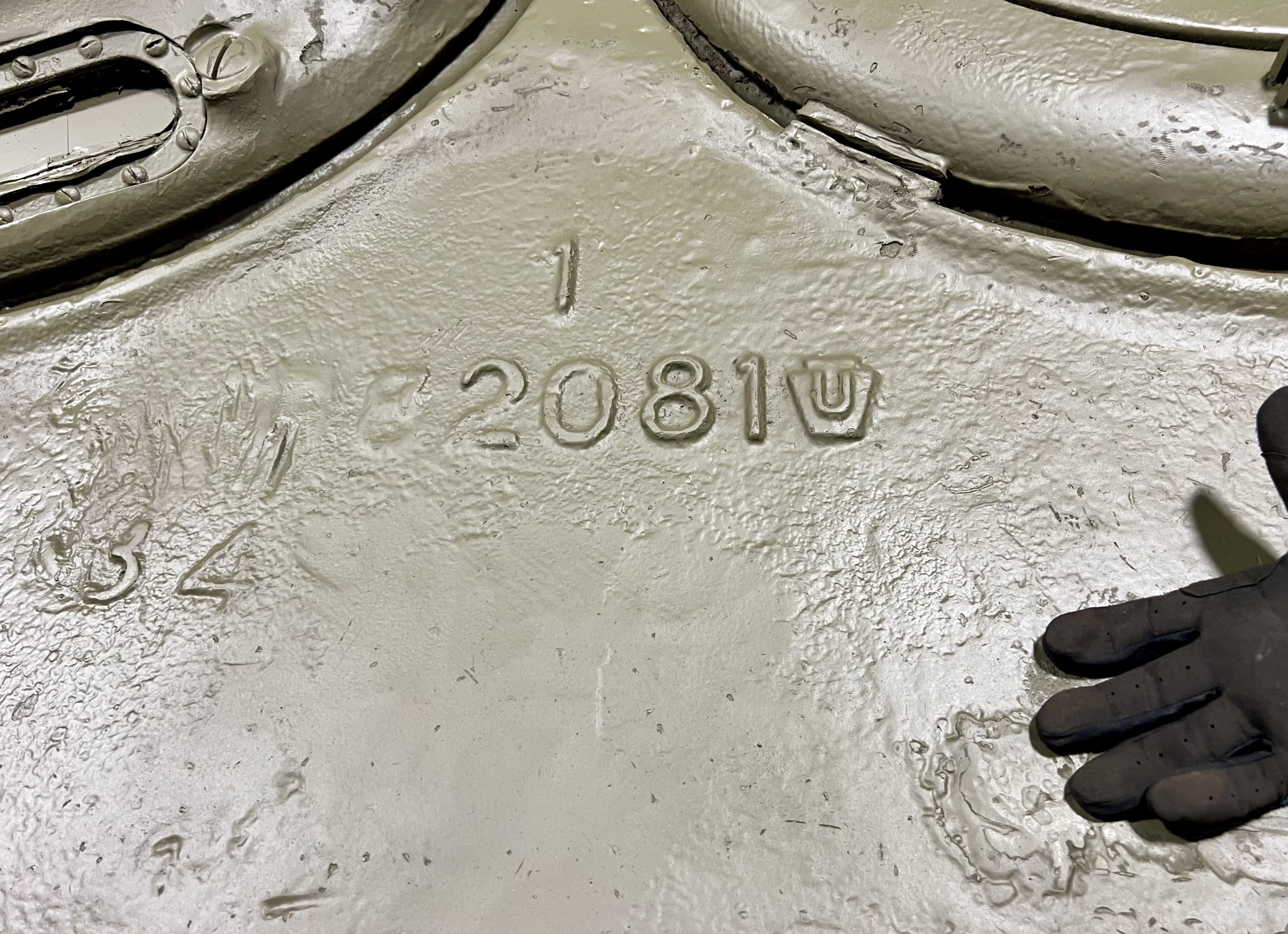
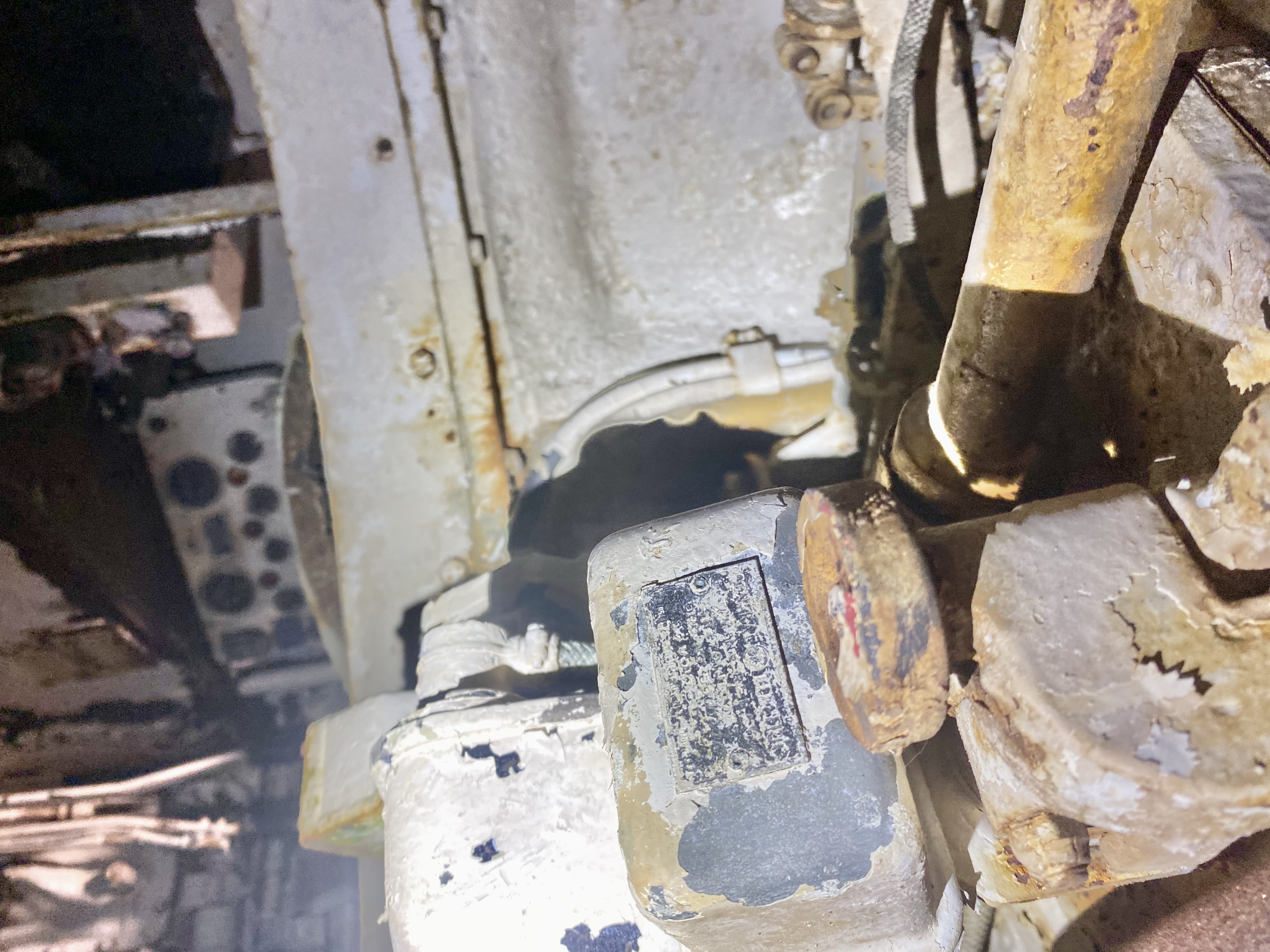
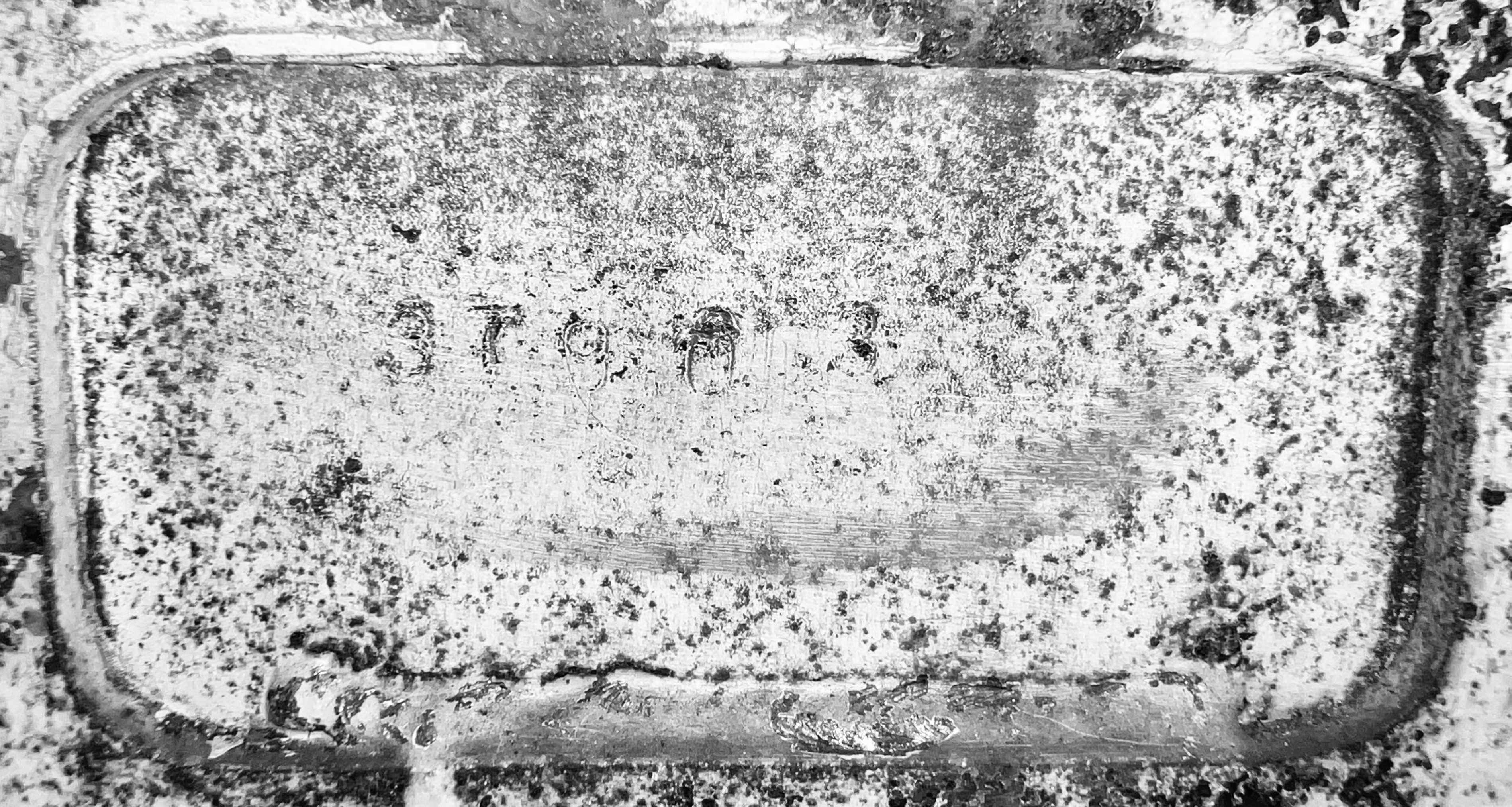
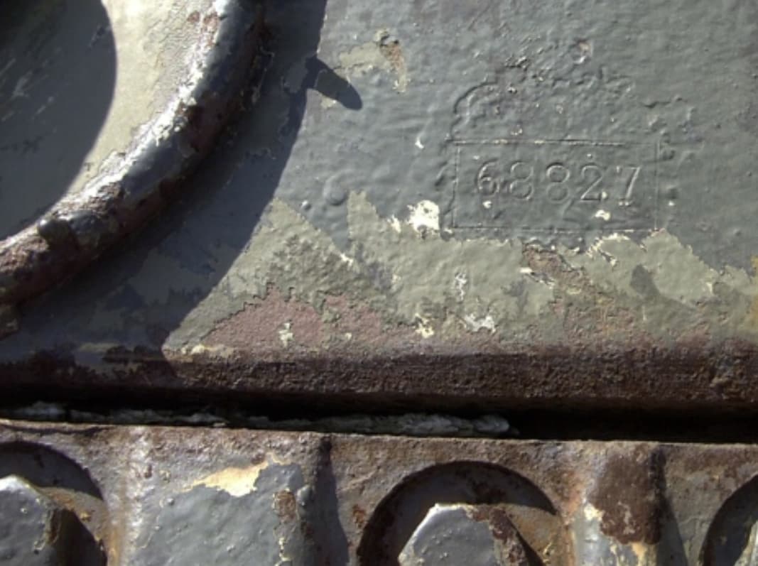
This is the SN! Located in the Driver’s Compartment, to his or her left, stamped into the metal inside a small rectangular (ish) frame. I’d heard this was common on PSC vehicles, and it was easier than trying to read the hull.
The very first batch of M4A1 (76)w VVSS were PSC, and the batch numbers started at 37900. This is 37903, the 4th tank in the serial. So it is representative of a very early version w/ a big-hatch, no ventilator turret.
Ted I have a request if I may:
Is it in its original OD color and, most importantly, is it correct?
![]()
![]() NO!
NO!
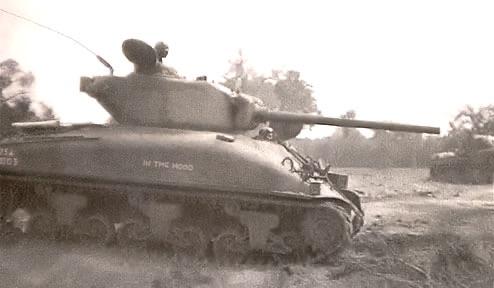
We are painting it per the In The Mood scheme taken in early sep 1944: two tone. Will it be correct?
Depends on the sunlight!
![]()
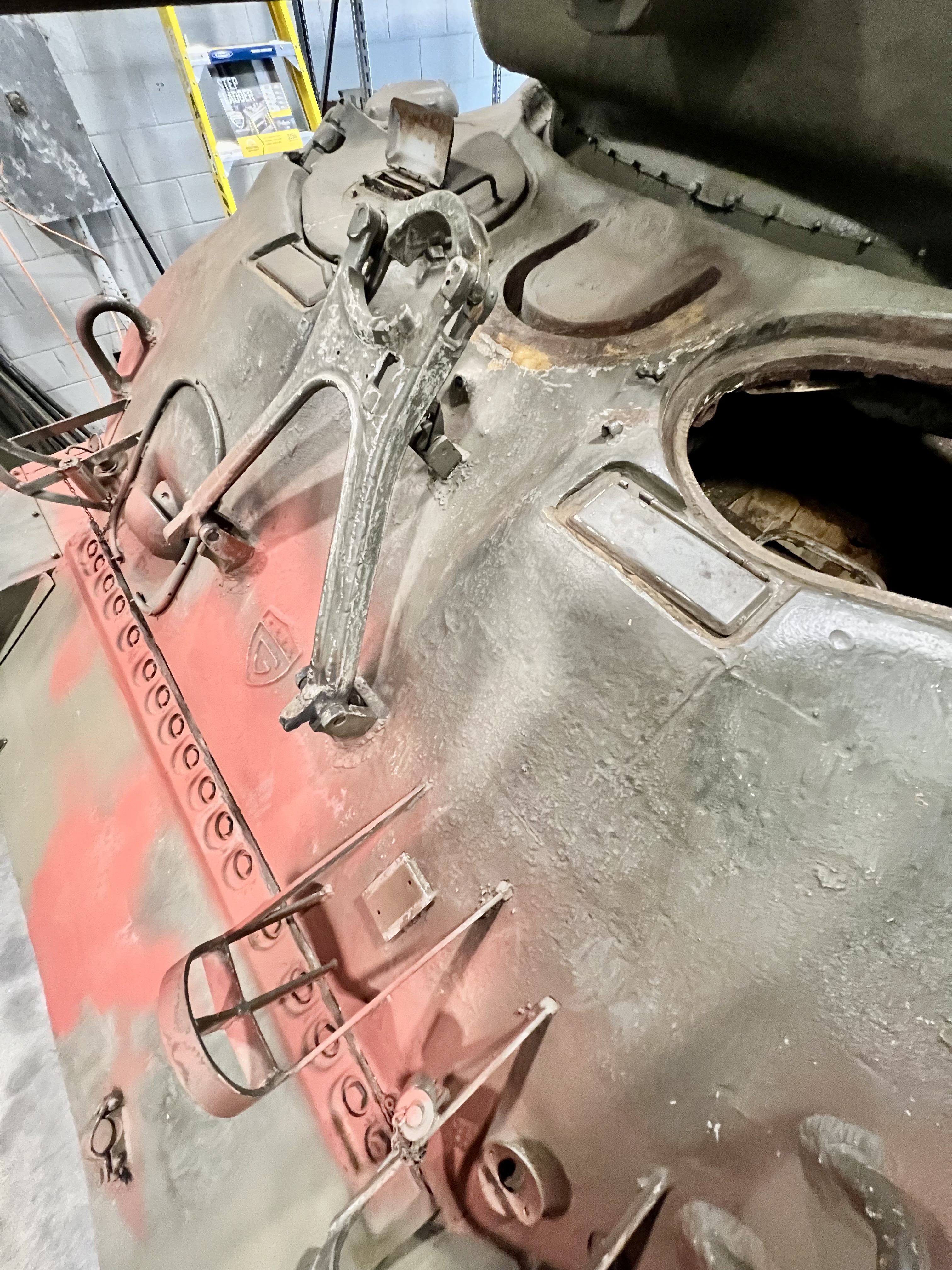
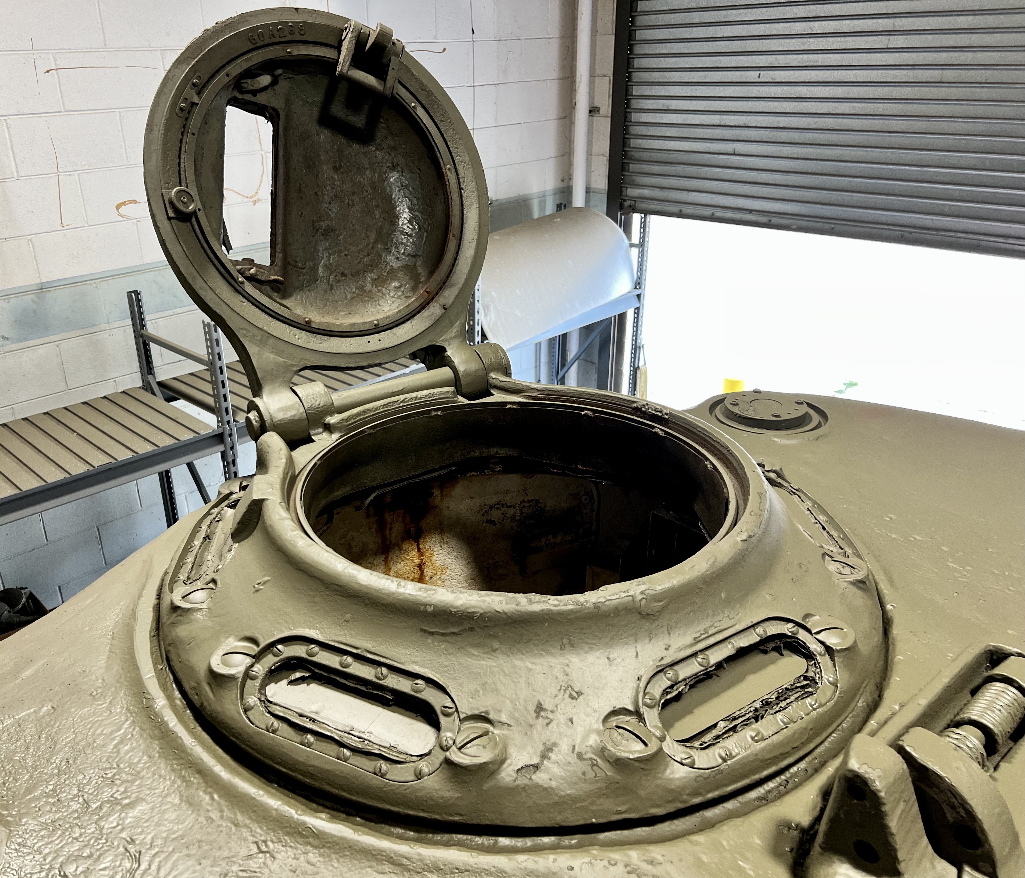
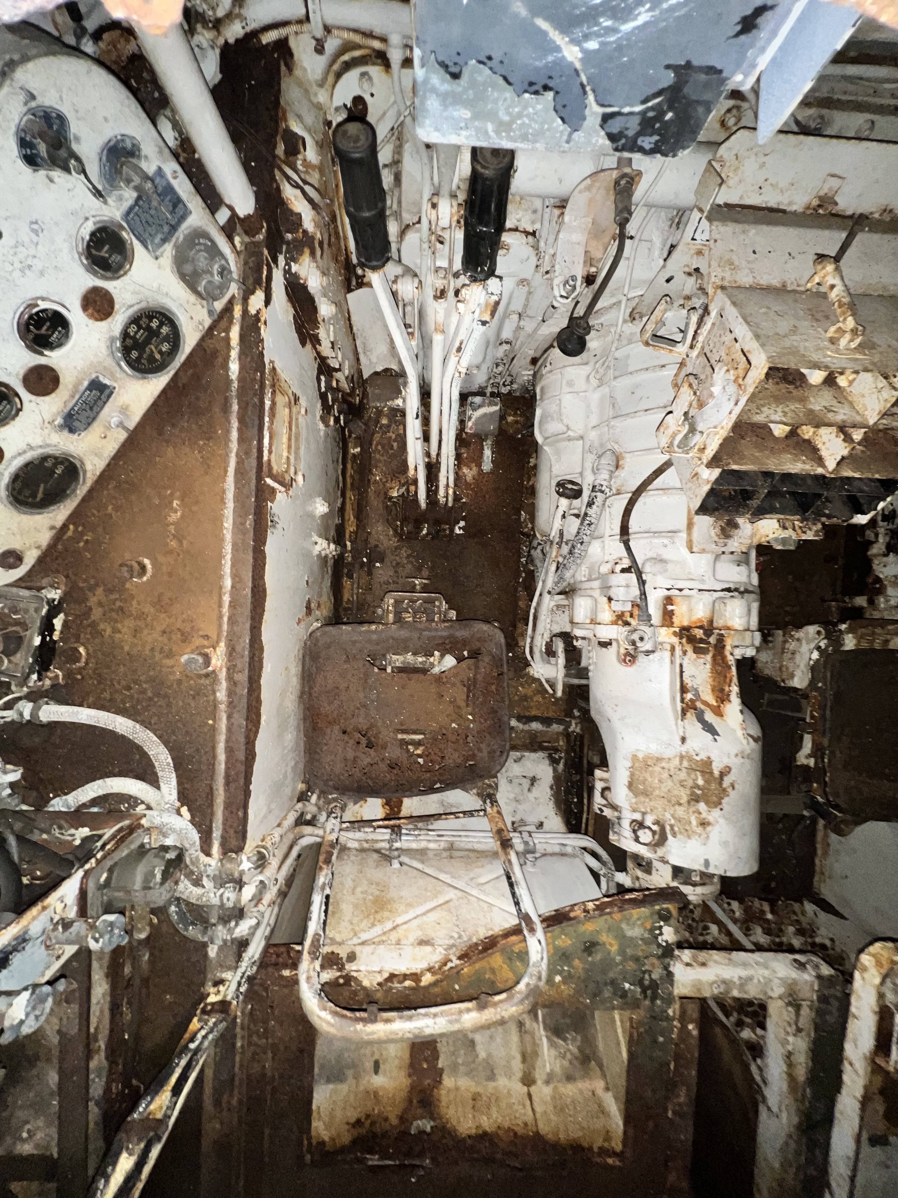
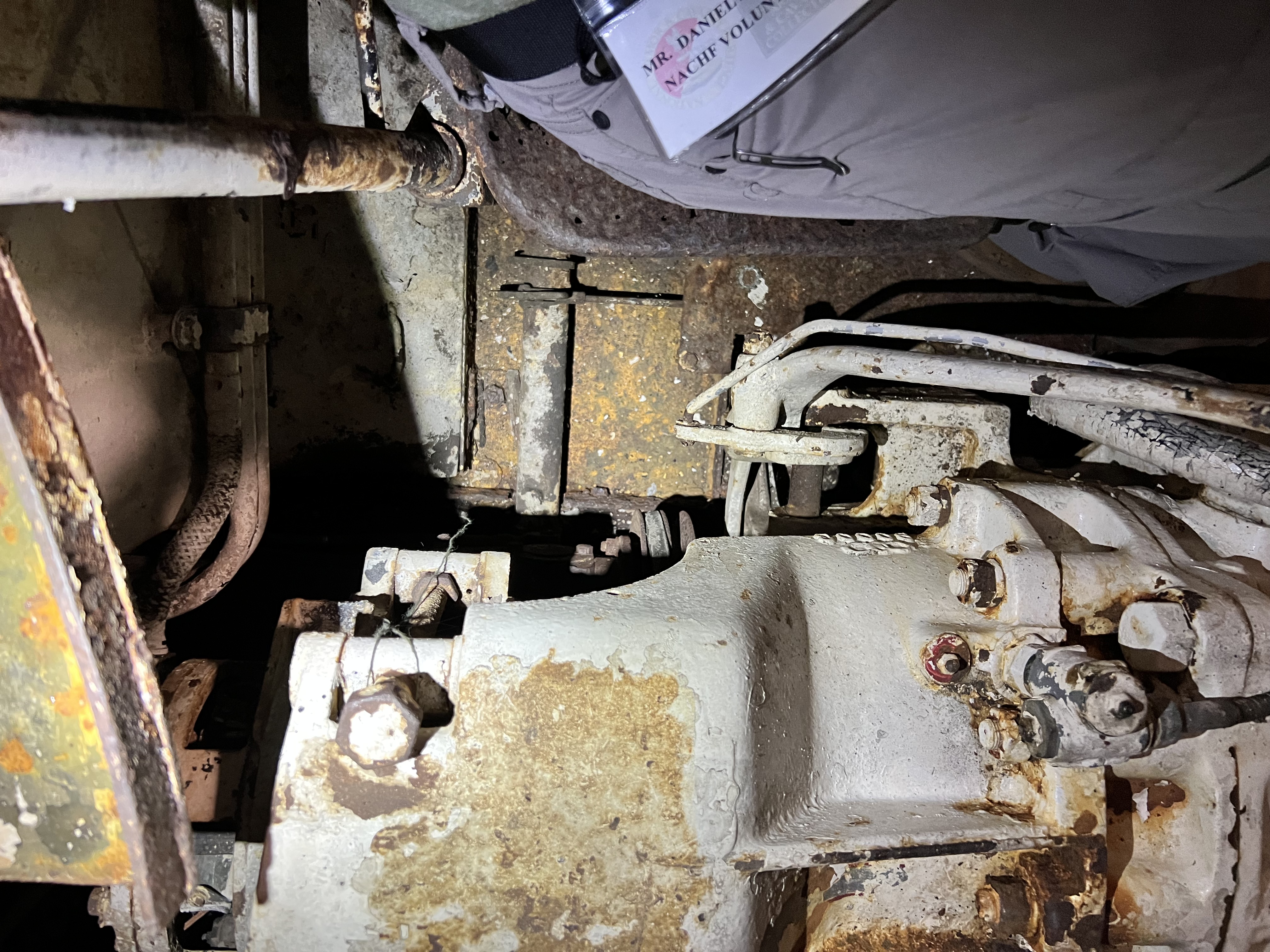
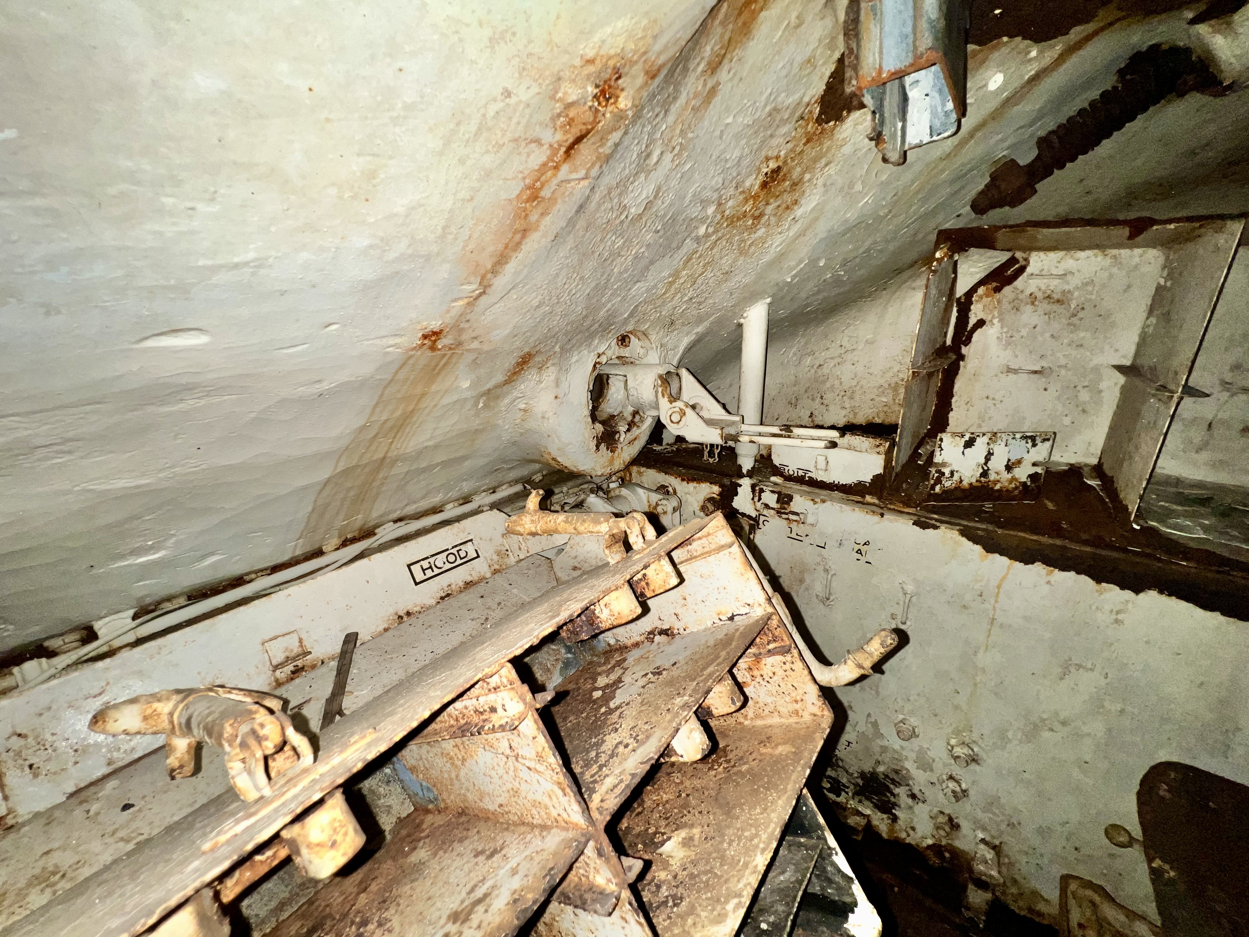
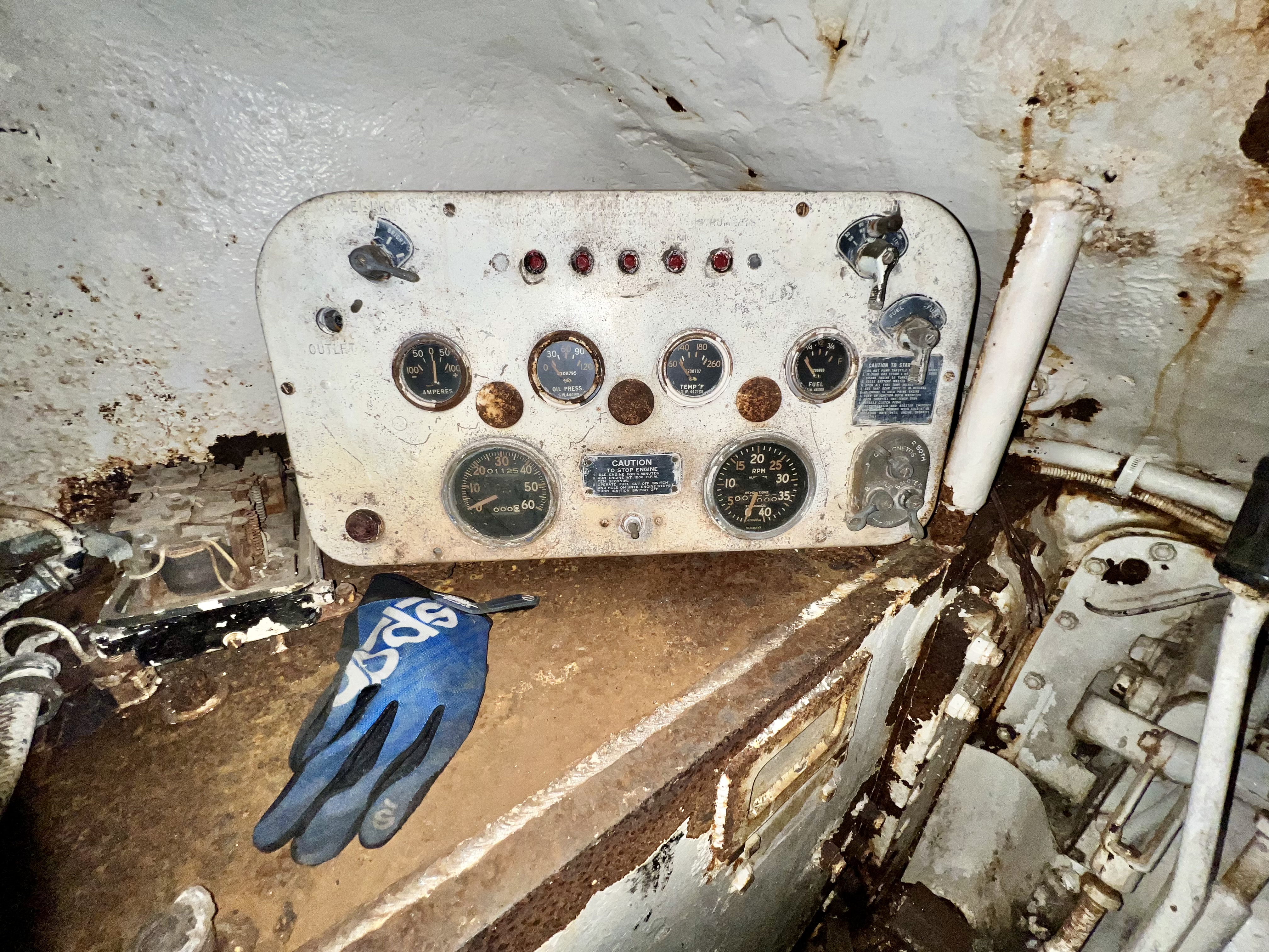
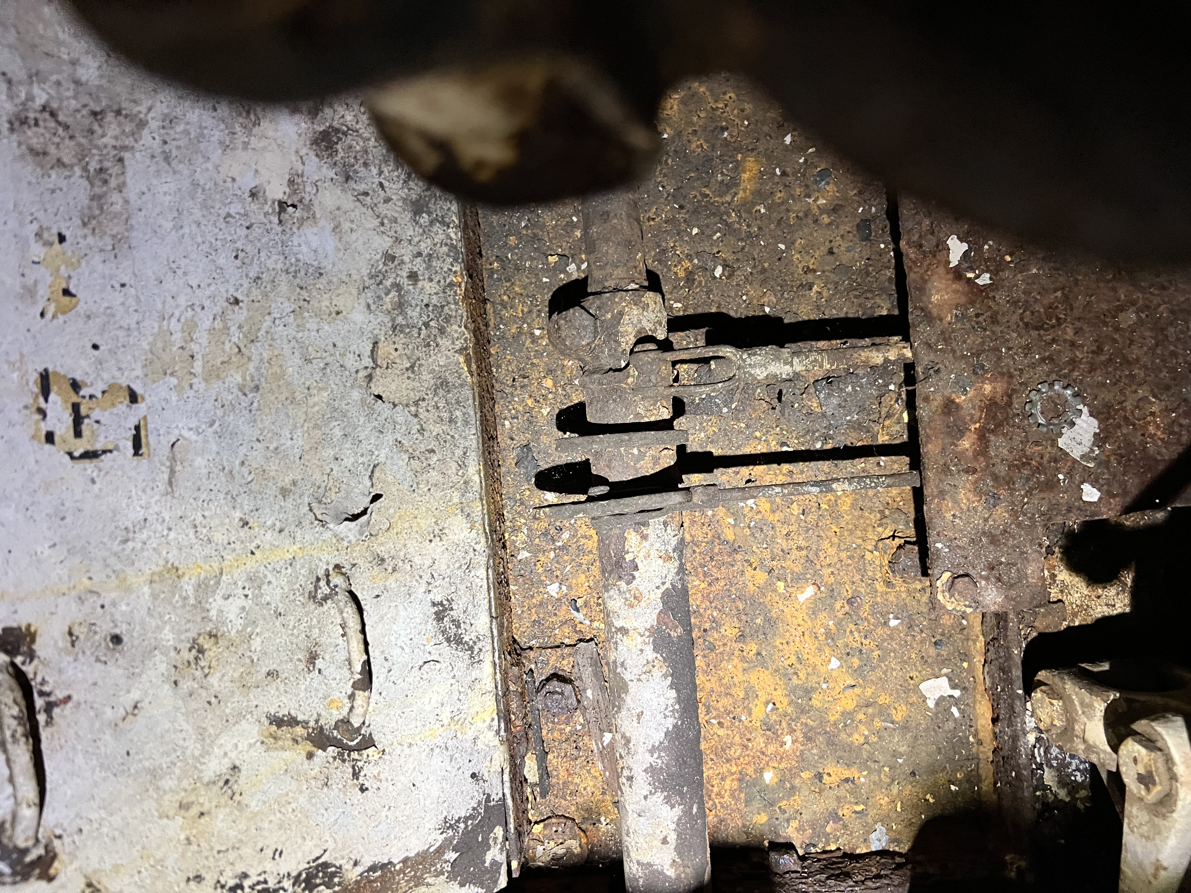
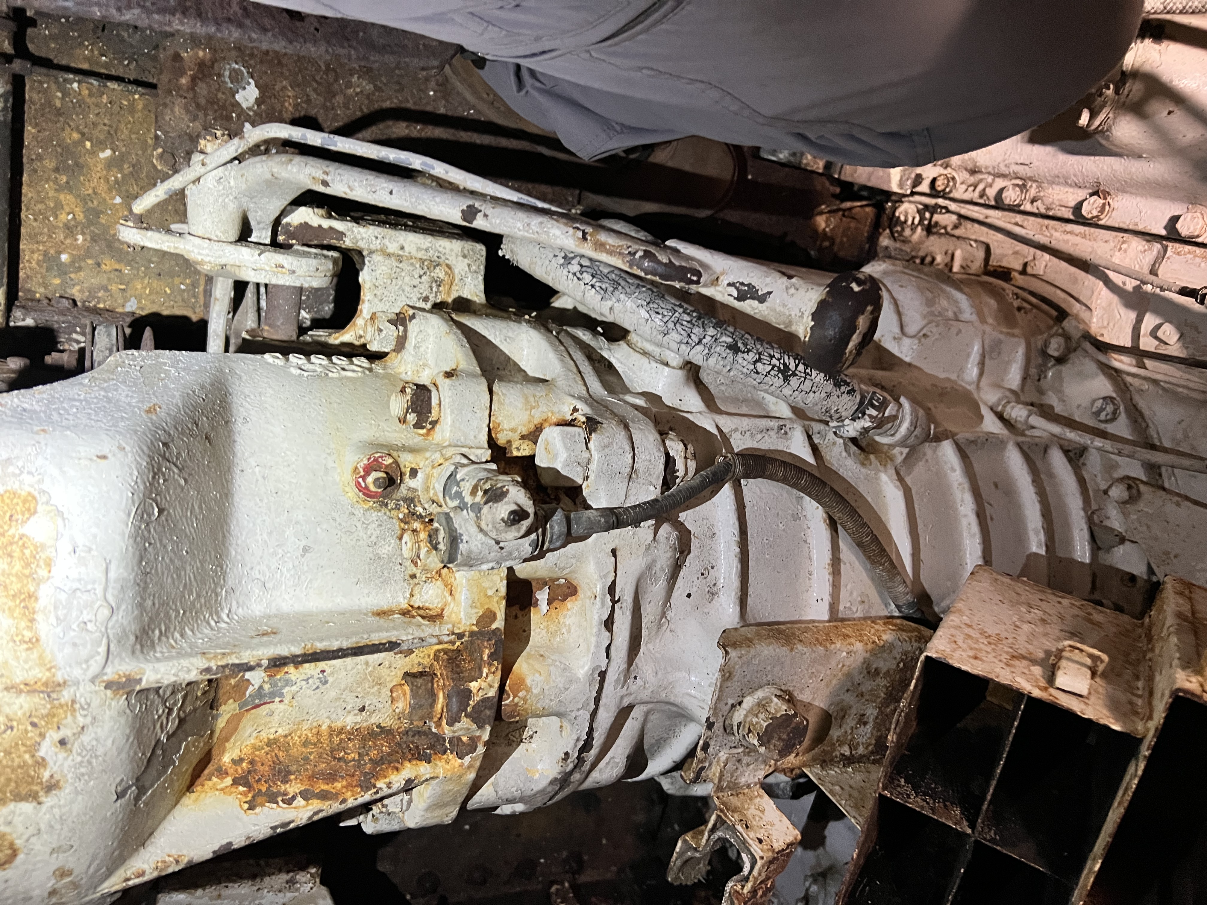
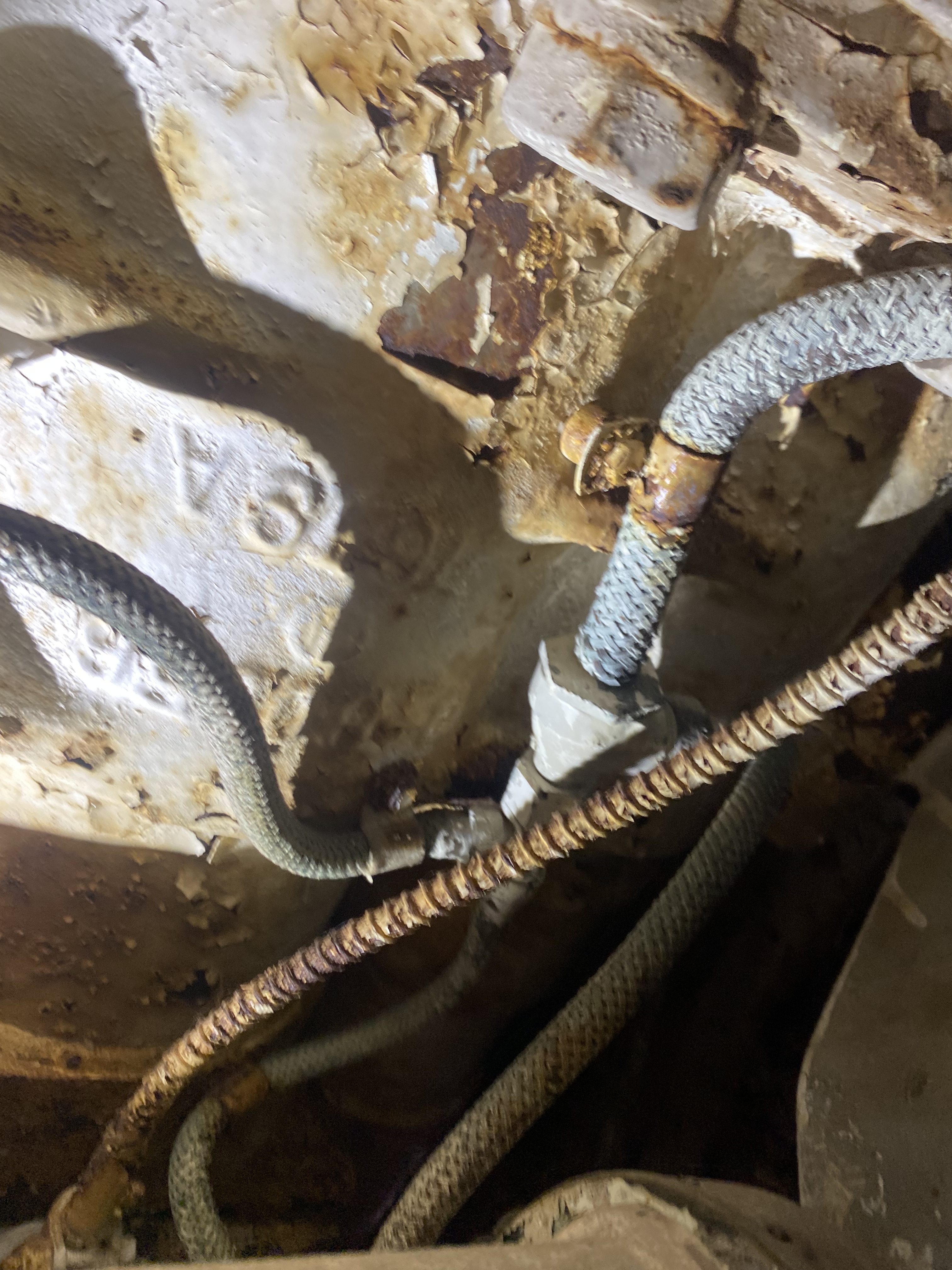
Some transmission / driver’s compartment shots.
Friday, we tried to rotate the sprockets. The first trick was to get the beastie in neutral. Done: we had a volunteer (young LT Daniel) who along with his dad (Matt) are trained on driving the M4 at the WW2 Armor group in Florida. After finding neutral (not Nemo) the sprockets were still snugly uncooperative. Well, the fun began when we confirmed that 1) the parking brake (PB) was set, and 2) someone had removed the PB Lever. OR, we need to learn how to use a steering lever-type PB pedal. Hmm. Too little time to investigate further Friday.
We are not amused (said the King of Restorations, retired WO5 Bob).
We have a few other issues: the cupola bearing races are jammed/corroded. We want to get them serviceable and put the loader cupola “gun forward” (see the M2 spigot on the exterior in pic above). The TC all-around vision cupola is a mess. Alas! We have 8-10 Lieutenants eager to move it and a few other specialty vehicles forward!
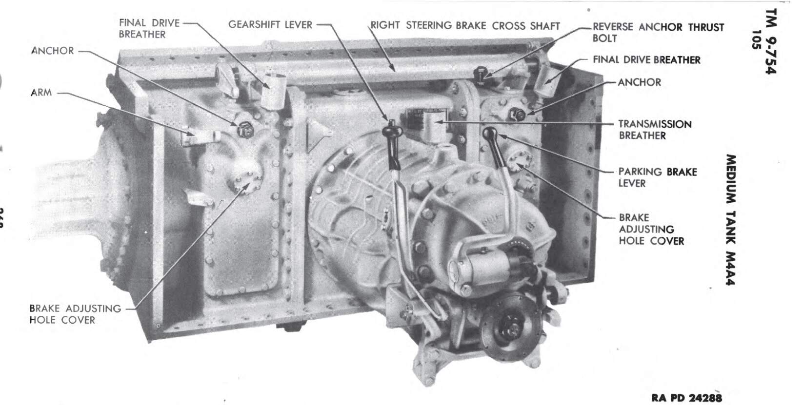
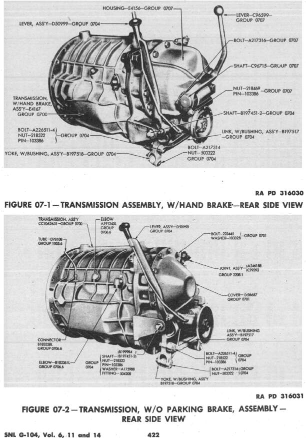
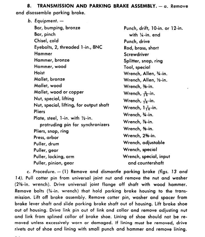
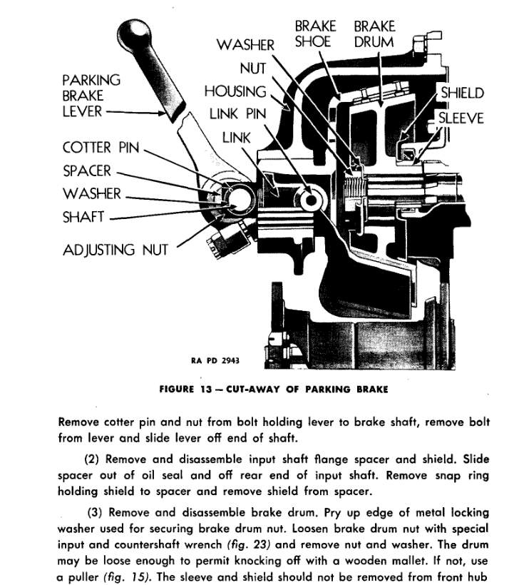
It looks like the transmission in the TM illustration you posted, with the ribbed bell housing, so it does have a transmission parking brake. Later transmission did not have a brake but had a conical cover over the rear.
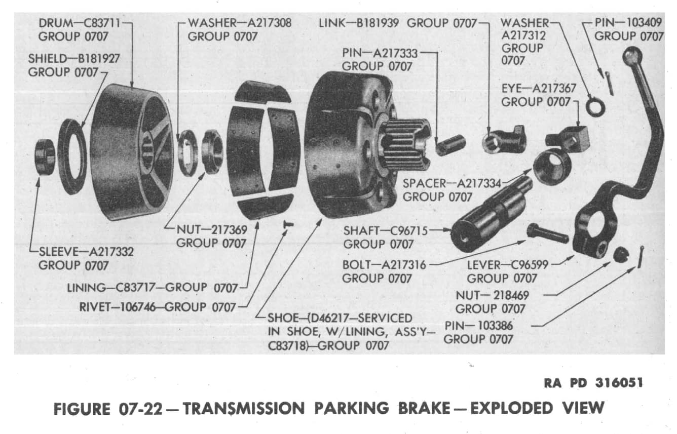
The brake handle is just split clamp attachment so it should be easy to make a replacement. It might be corroded together forcing you to remove the bolts holding the housing on and get to the brake itself.

What was the question with the barrel length? The drawings for the tube exist so there shouldn’t be any question as to dimensions.
Was there a stamped marking on the rear hull?
If it is ex-French, there might be a stamped serial on the glacis.
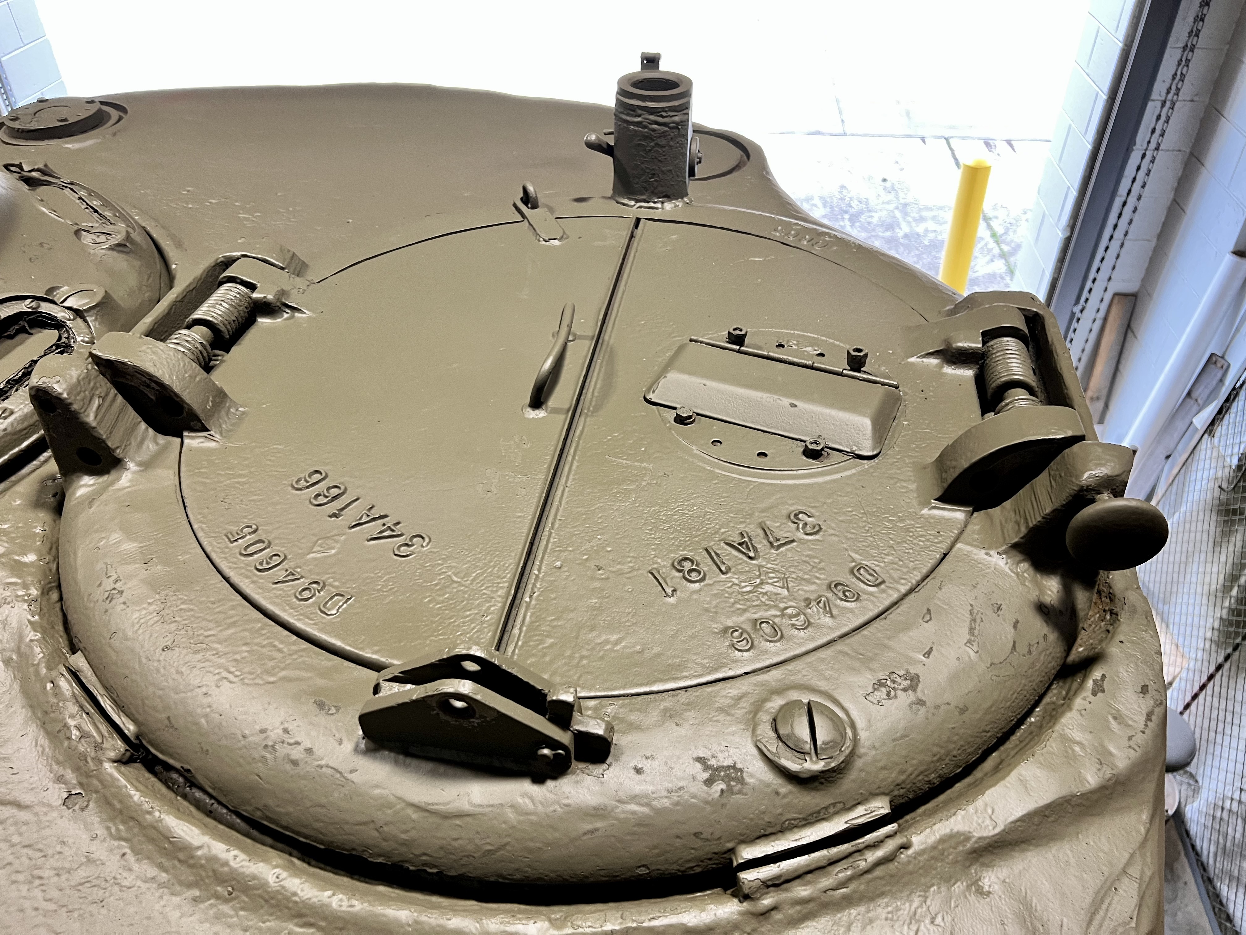
You’ll probably need to unbolt the cupolas to get anywhere with them.
KL
Thanks Kurt!
We did not have that transmission manual in the bay. It definitely lacks that conical cover. I’m sure the LTs found out, and I know we’ve been in contact with WW2 Armor in FL. No one in the collection has current maintenance experience with the M4.
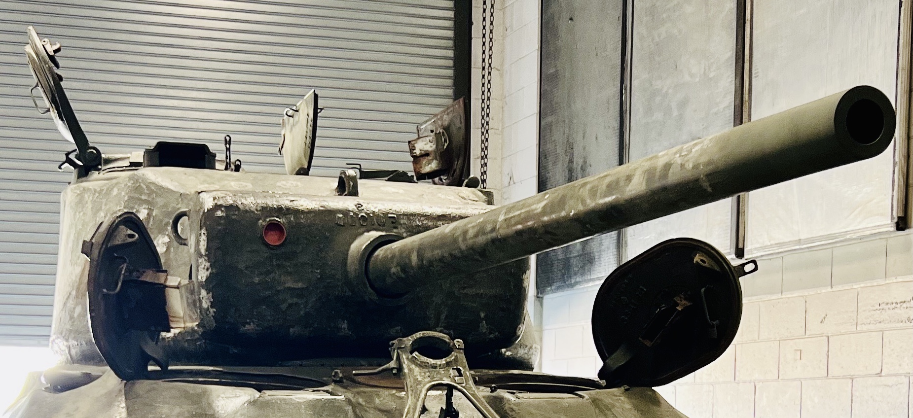
Gun tube as more a question of finding the data and ascertaining who made it. Remember, we “capped” the muzzle with an extension after removing the Brake. The muzzle brake is laying on a shelf in the bay! So more a question of did we measure right for added length.
The rear hull stamping was covered or obliterated on the right side. I walked around the FDC and climbed in, and then found the embossed SN in the driver’s compartment. We got excited and I hadn’t checked the left side, or anywhere else. I poured over your work at the Minutia site too. Did not look yet at the FDC for a marking similar to what you’ve shown.
Thanks for all the insights! I’m going back down next week on Tuesday or Thursday. Will advise!
TED
If you mean that you added a sort of thread protector to simulate the M1A1 tube contour, the tube length never changed from M1 > M1A1 > M1A1C > M1A2, so the extension should be flush with the end of the existing tube and carry the same taper to the end.
It’s on the hull,not the differential housing.
KL
I’m going to verify the length. I saw the extension before painting. It wasn’t the length of the caps: Ive seen those.
We’re recreating this:
The French stamping is just above the FDC at the bow gun, yes?
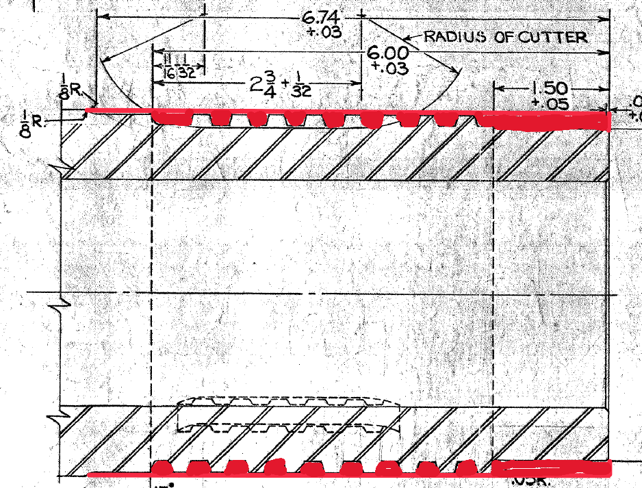
By “caps”, do you mean the thread protectors that were issued before muzzle brakes were available? That’s got nothing to do with what they are doing now, which is to make a threaded tube look like an M1A1. For that they have to replace the metal that was removed by muzzle thread machining. Ideally they would make a sleeve that fits over the thread and other muzzle features with an external contour that matches the rest of the tube (0.01683 inches diameter / inch taper) and ends flush with the existing tube with a 0.10 inch corner radius. They probably still will need some Bondo to fill in the groove at the breech end unless their machinist is willing to do a bit cut-and-fit to match the joint.
It’s on the glacis. You said earlier you were going to look on the “FDC”, which is not close to the marking site.
The Final Drive Covers are the teardrop-shaped castings on the sides where the sprockets mount. The large casting in the front center of the tank is the Differential Housing. The large assembly that is bolted onto the nose of the tank that includes the final drive covers, differential housing, carrier, and the final drives, differentials, steering brakes, and so forth is the Final Drive Assembly.
KL
Morning Kurt!
I was up in the mountains all weekend. Thanks for the detailed information.
I said earlier I wanted to measure the OAL of the barrel. The extension was mounted previously, and naked. I had a pic, but I’ve shelved it somewhere. The extension appears longer than even the length of the muzzle brake laying on the shelf next to the tank. As for the work, your surmise is correct: a tapered extension. But installed, it does not end flush with the existing tube. I’ve got more work to do.
You’re correct: I’ve conflated the terms FDC and transmission/differential cover. I can point to the location o which you speak and will see what if anything we find! I suppose that’s a hazard of getting older.
Thanks!
Is the bore clear all the way through? Is the breech block (not the breech ring) still in place? If so, can it be dropped to expose the end of the tube?
KL
I’ll find out next week. The LTs detailed/volunteered say the bore is clear. I don’t know the other details yet. Thanks!
I took pics of the breech ring but have been unable to process them to reveal the tube data. Tried getting an etching. No go. Need the wire brush and some naval jelly (not navel).
Best I’ve been able to see so far-
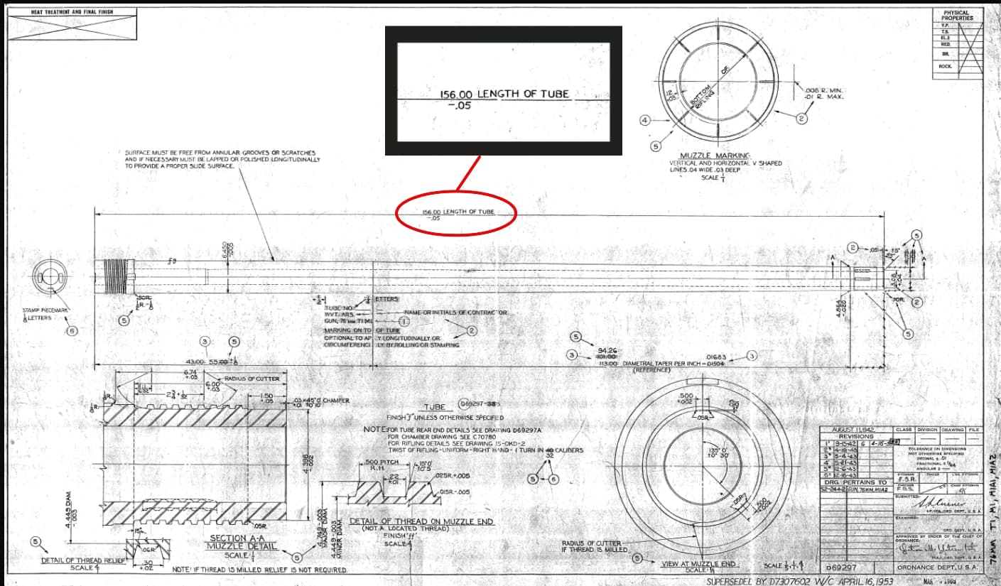
Well then, if you feed a tape measure from the muzzle down the bore and hook it over the rear end of the tube seen in your photo, the end of the muzzle - if the gun is the correct length - should be at 156 inches.
KL
If I understood what you guys wrote, the extension is going to make the gun longer because it was brought out to the full length of the gun including the MB? So if I understood Kurt the gun with threads was still the same length as the original unthreaded version even when it didn’t have the MB installed? So the MB adds a bit of length to the original gun but this extension should not have added that extra length?
On the positive side if some model company bases a new “Cobra” kit on your restoration then we’ll all get an extra long gun on our tanks, LOL!
That is my next step. I’ve a long tape measure that is literally nuclear grade: it bends very little even at full extension. I needed the length.
I plan to go down next week. Will advise.
Great pic, Kurt. It’s interesting to see the dates (starting with August 1942 for Rev 0), so that draws a line about how Ordnance was thinking about tank guns it seems.
The developmental T1 76mm gun (of which two were made) had a tube 171 inches long. Before standardization it was decided to reduce the tube length by 15 inches.
The standardized M1 76mm gun had a 156 inch long tube, a plain muzzle, a 43 inch long recoil slide surface, and a 1 in 40 rifling twist.
The M1A1 76mm gun had a 156 inch long tube, a plain muzzle, a 55 inch long recoil slide surface, and a 1 in 40 rifling twist.
The M1A1C 76mm gun had a 156 inch long tube, a threaded muzzle, a 55 inch long recoil slide surface, and a 1 in 40 rifling twist. Some were made by machining threads on existing M1A1 tubes.
The M1A2 76mm gun had a 156 inch long tube, a threaded muzzle, a 55 inch long recoil slide surface, and a 1 in 32 rifling twist.
The taper on the muzzle end of the tube changed when the recoil slide length changed with the diameter at the muzzle face staying constant. The threading at the muzzle did not change the taper.
A replica of the M1A1 gun made from an M1A1C or M1A2 tube should only have material added as shown in red below because this is what was removed to make the thread.
If I was doing it, I would machine a 1.50 inch long ring for the end, fill the threads and thread relief with Bondo, contour it when wet with a straightedge, and sand it smooth.
KL