Similar discussion on scaling from photographs published previously on the Armorama pages:
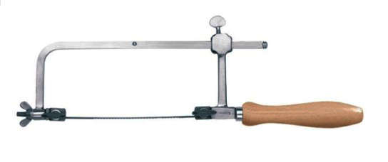
As said earlier, I tried using the stock Tamiya Dragon Wagon frame just shortened slightly. Then I discovered the Mack had had a stepped frame so I went back to the cutting board. (Jeweler’s Saw cutting that is.)
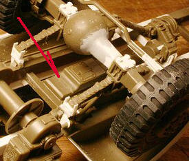
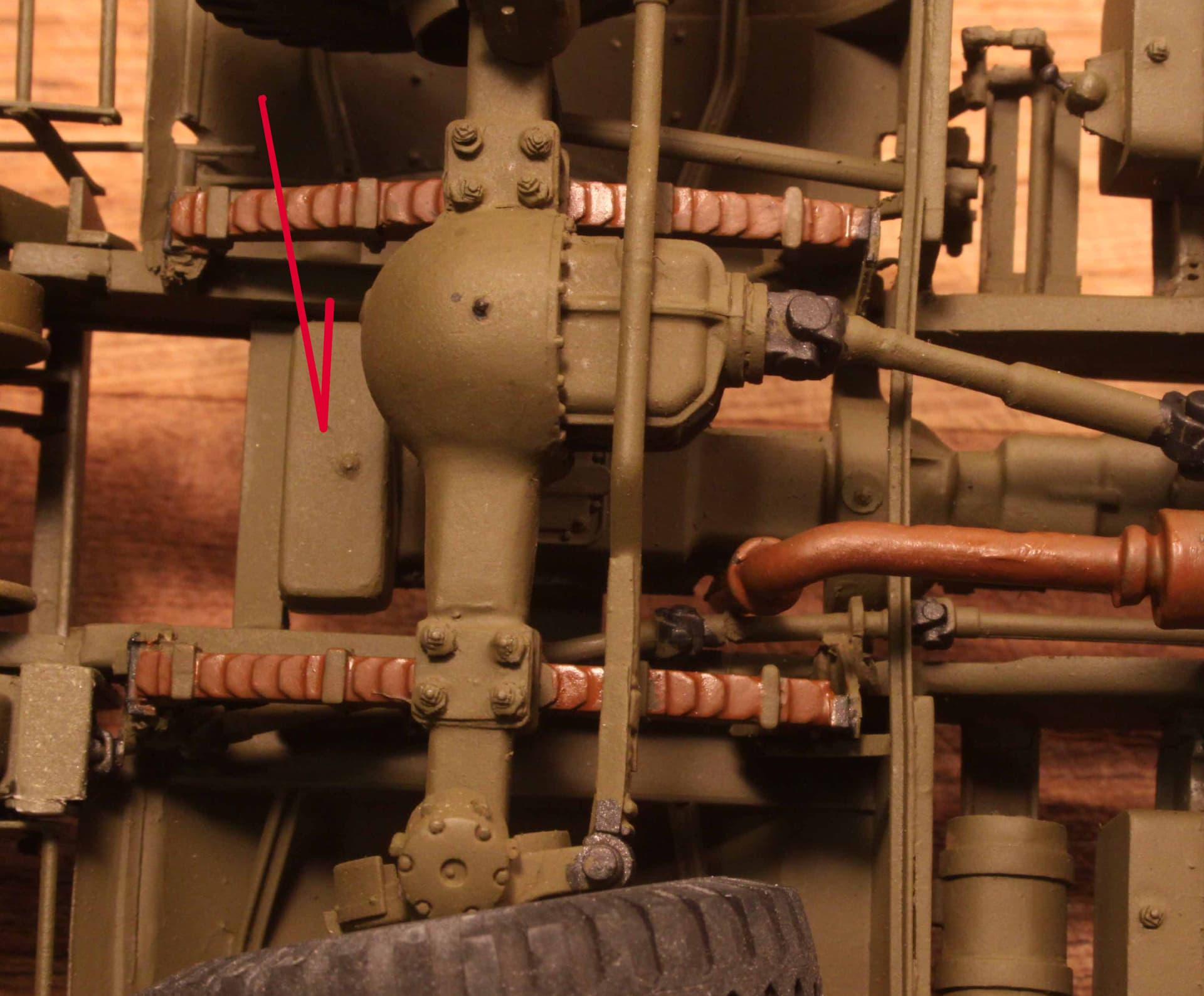
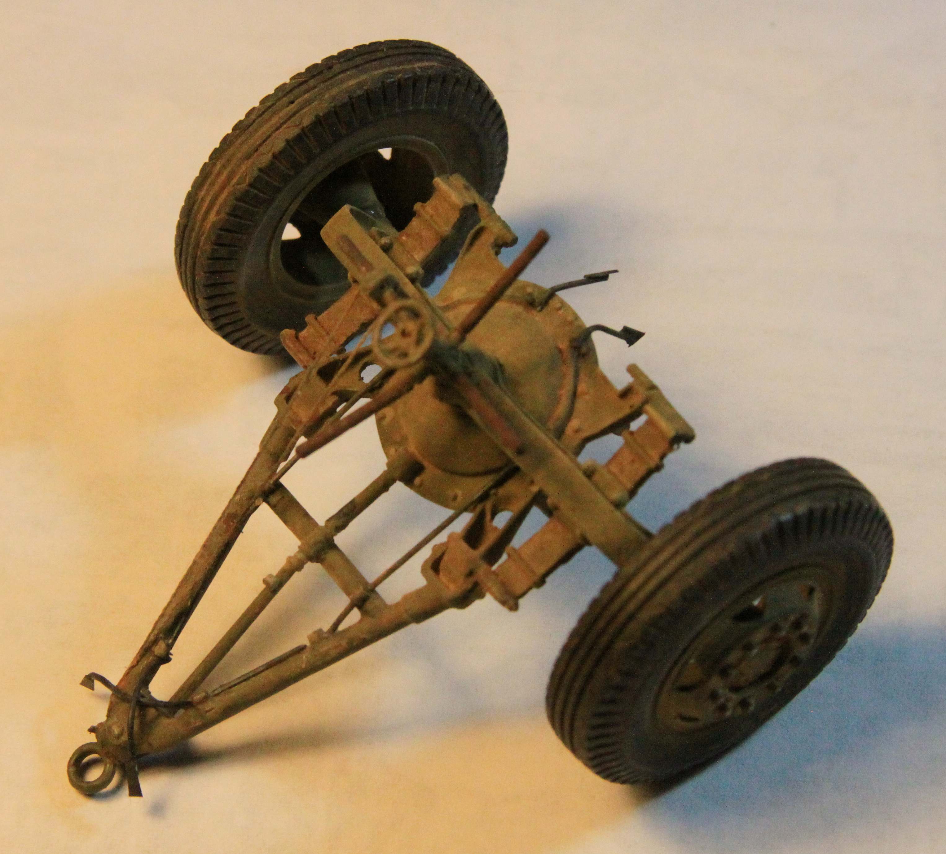
I did use the rear axle support towers from the stock DW with the detail additions your see here.
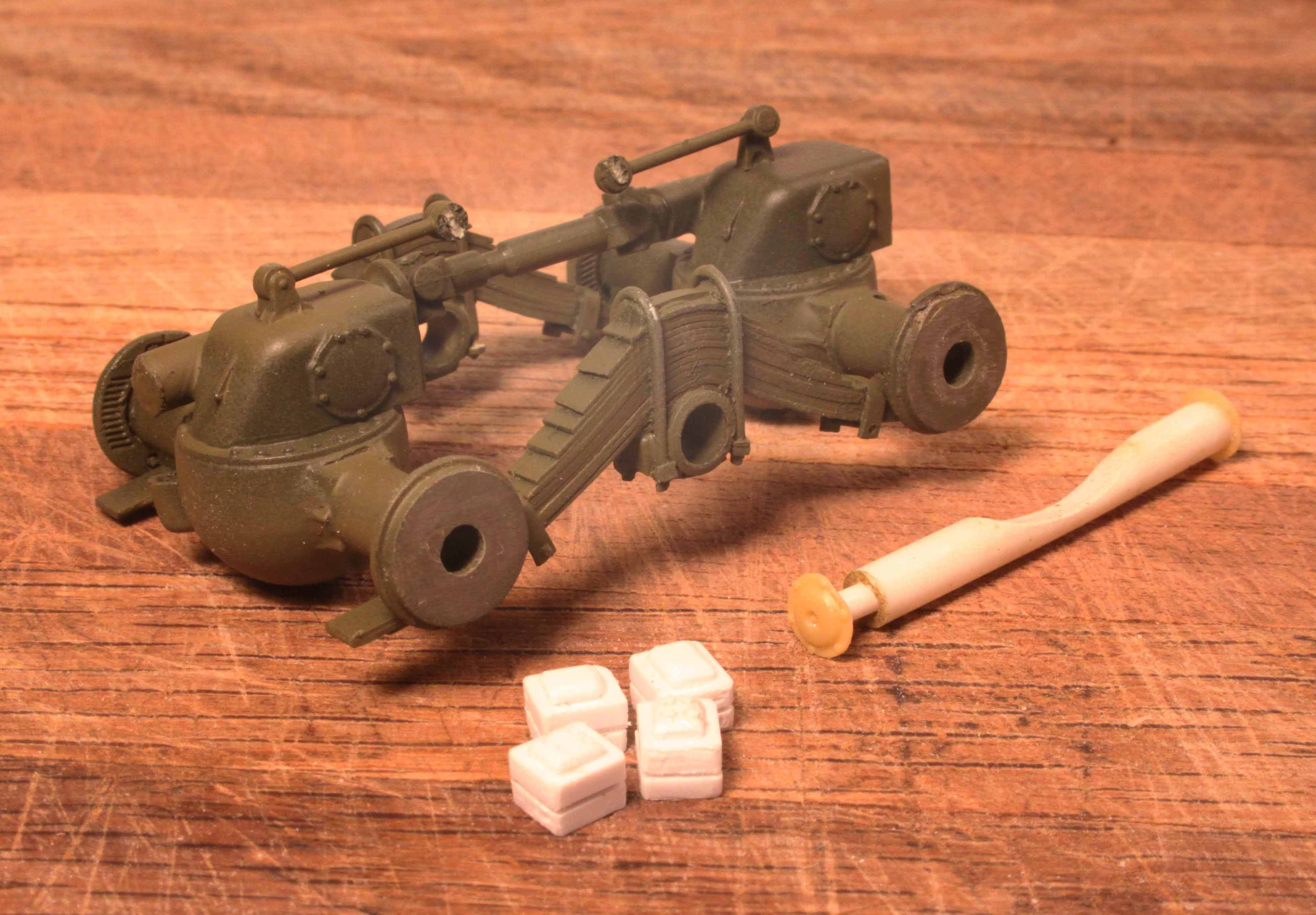
Central bogie pivot rod and spring cushion blocks yet to be added to the axle assembly.
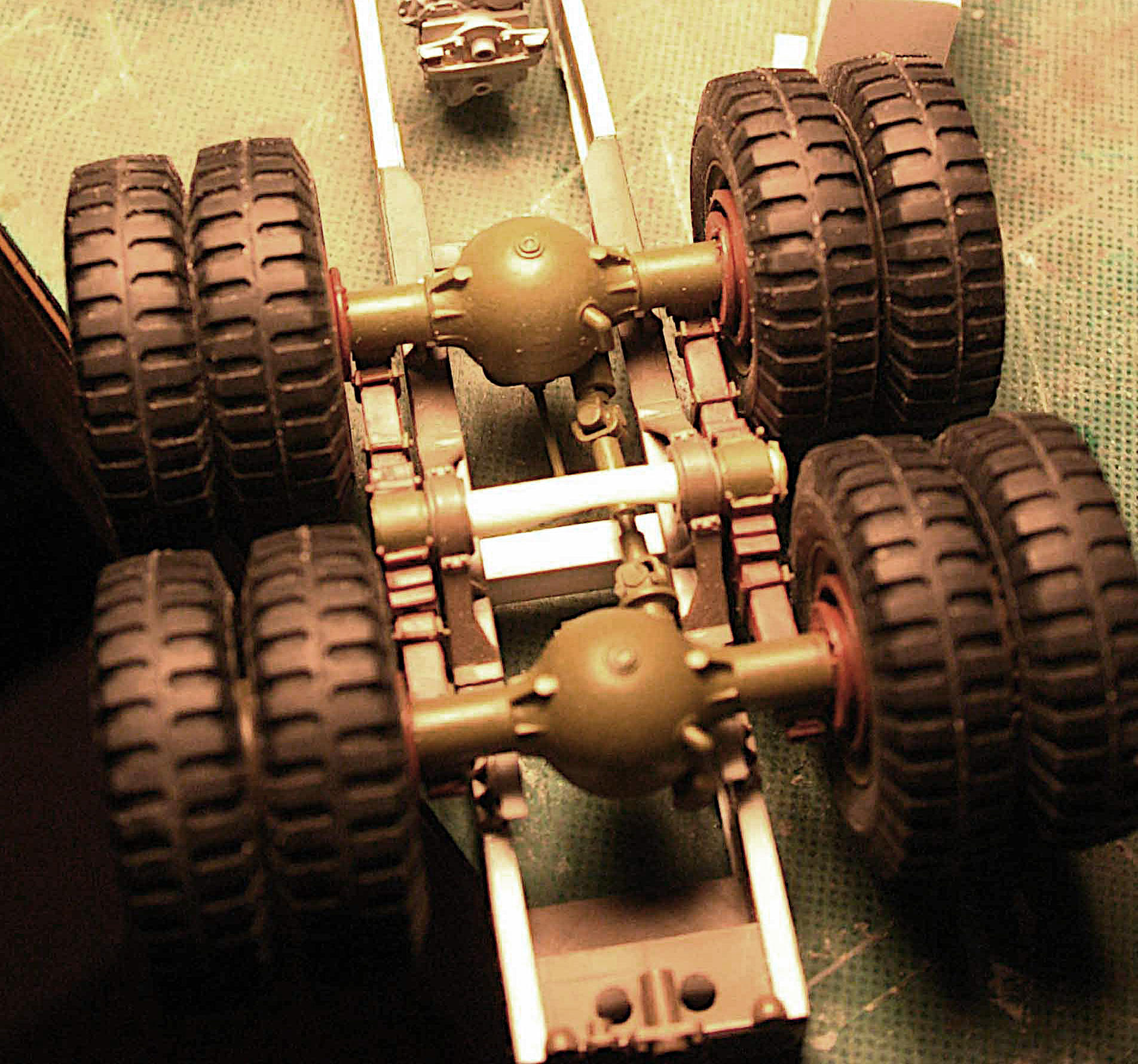
The entire 2-axle bogie does pivot on that central rod to allow the model vehicle to better conform to whatever surface it may be sitting on.
_________________________
_________________________
I am sorry but I don’t seem to have much photo documentation as to how I went back and created that vertical off-set in the DW frame. I fear my off-set seen here may not be as pronounced as that of the real vehicle but this feature is well hidden and I think, poses no modeling problem. Perhaps should some one else choose to scratch build a Mack NO they will fabricate a more correct frame than mine from scratch.
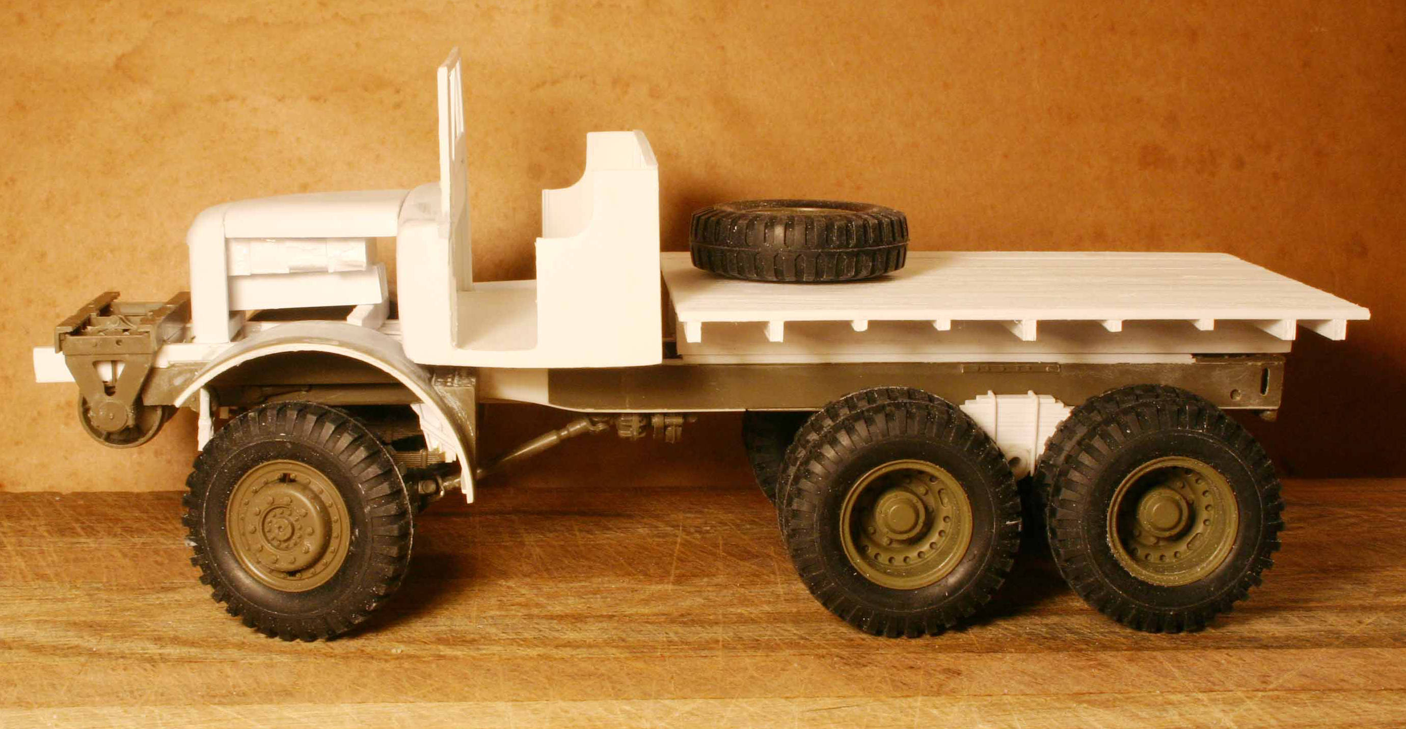
In this photo just above I still have the incorrect rear leaf springs installed
and the spring towers for the front leaf springs are still much too high.
So the entire vehicle stands here as being WAY too tall!
2 Likes
The Engine ~ or the Lack Thereof:
At the time I had little reference on the engines used in the Mack so chose not to attempt one. I did shorten the oil pan of the DW engine and utilized that for the engine oil pan. The Mack used a smaller bore in-line 6 cylinder engine than the DW so a shorter engine block and oil pan is logical. However in the finished engine this cut line cannot be seen for it is blocked by the very large oil sump employed on the Mack
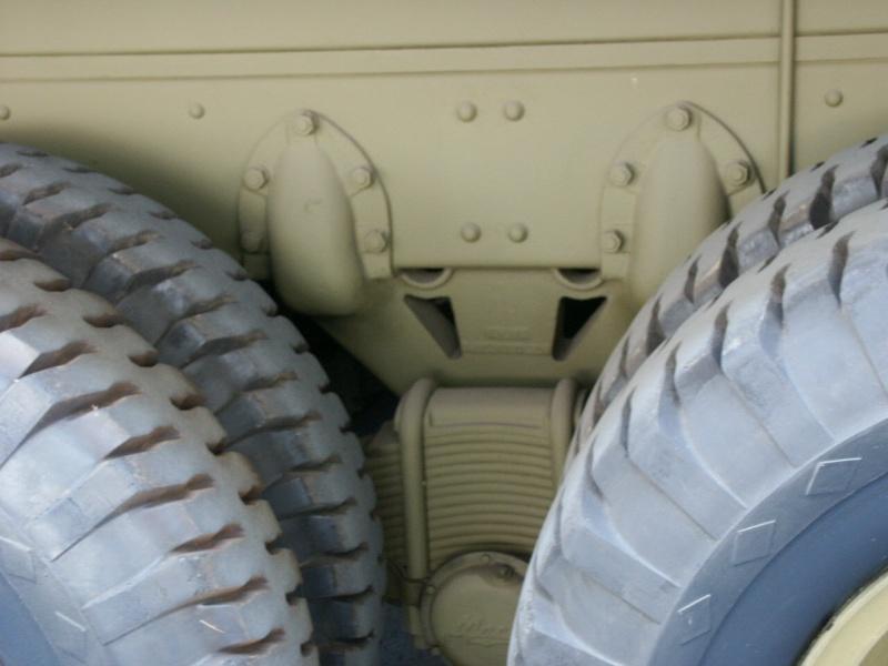
Seen below is the large oil sump and drain plug I added to my engine.
4 Likes
Never realized this was a gasoline powered Mack. I always assumed (incorrectly) it was a diesel.
Quote: (From the Olive-Drab website:)
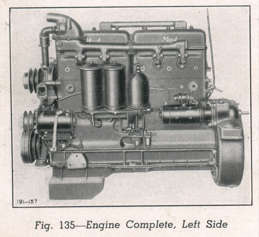
The huge Mack NO 7 1/2 Ton 6x6 Truck (G532) weighed almost 30,000 lbs empty, could load another 10 tons and pull 25 tons. It was powered by the Mack EY 6 cyl. 707 cid engine with 159hp@2100rpm and 534ft-lb of torque at 800rpm. It had a 5 speed transmission mated to a two speed transfer case.
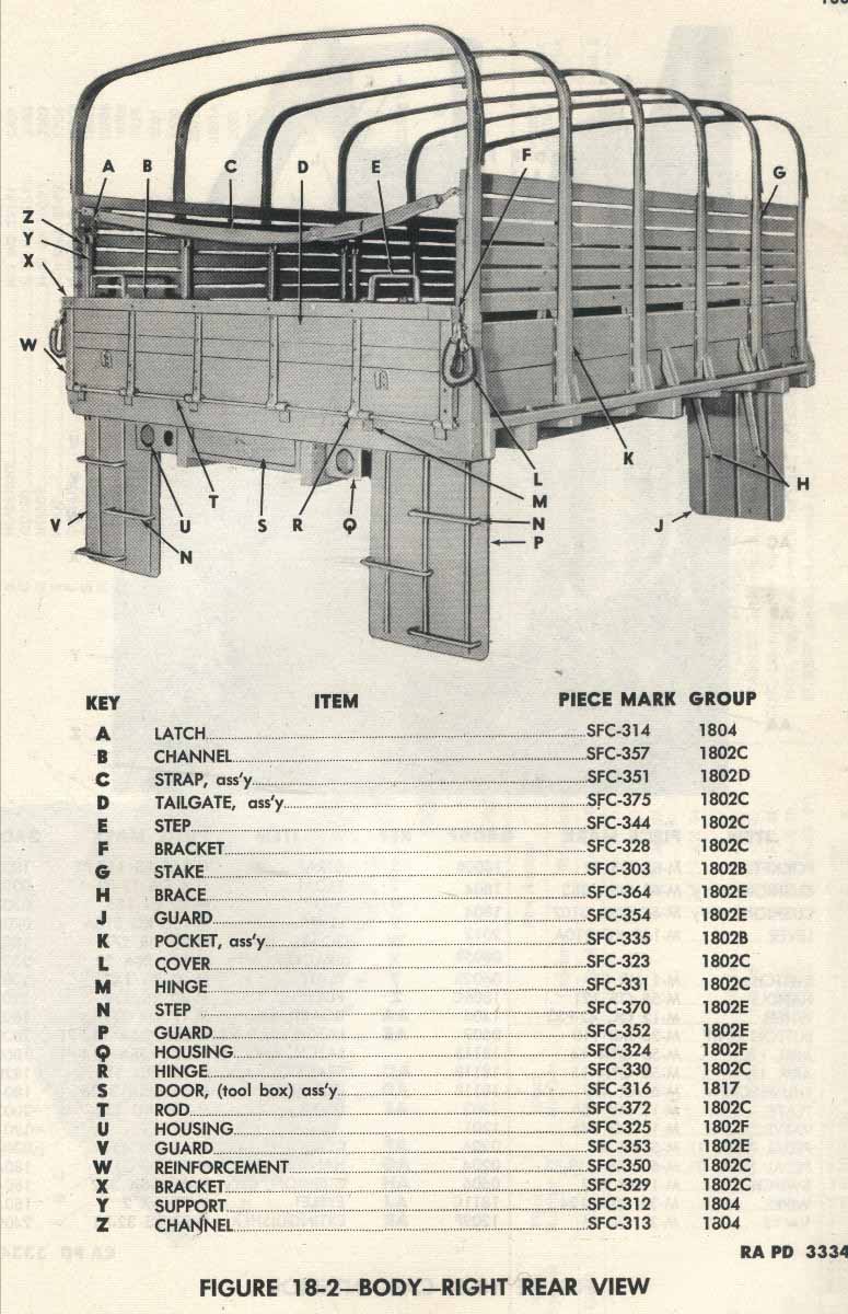
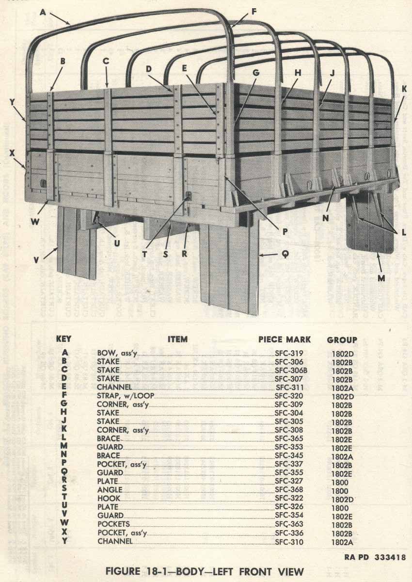
Manuals for this series of trucks include:
- Parts List: ORD 9 G532
- Operators Manual and Maintenance: TM 10-1679
End Quote
Honestly I have never seen any statement one way or the other to tell if the Mack EY engine is gas or diesel.
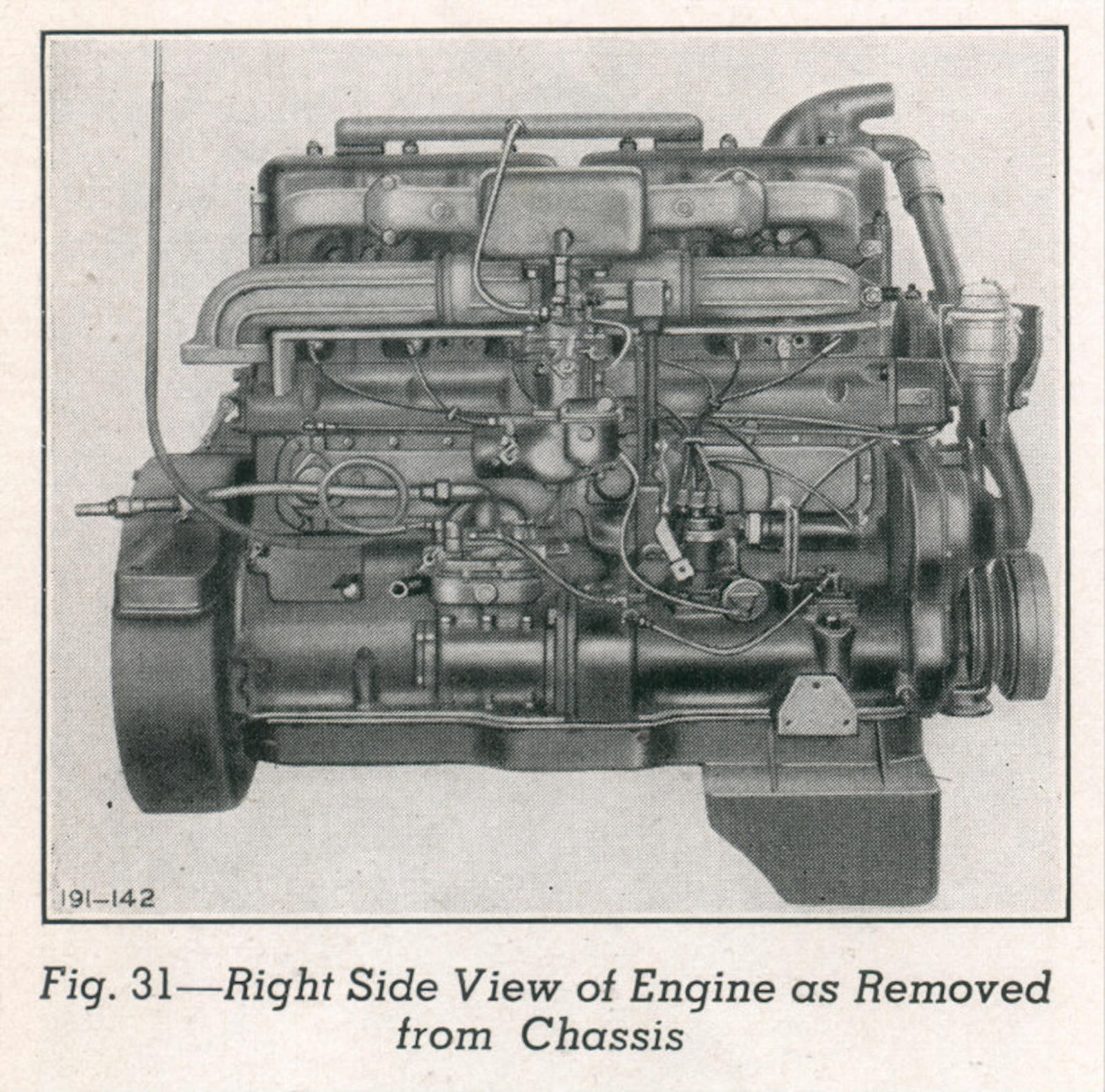
Perhaps other more knowledgable folks can tell by simply looking at the photos of the engine.
That certainly looks like a gas carburetor mounted on the engine right side and feeding to the intake manifold.
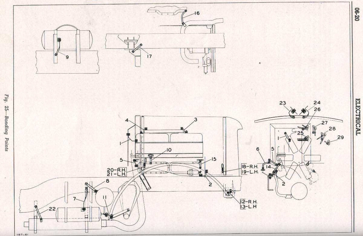
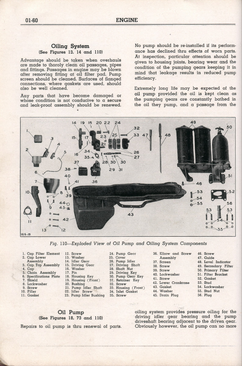
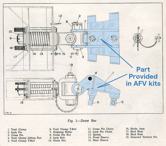
Pretty sure it is a gas engine. The below diagram lists #7 as the carburetor and #8 as spark plugs, neither present on a diesel engine. Also, diesel was not popular and the military didn’t really transition to it until after WWII.
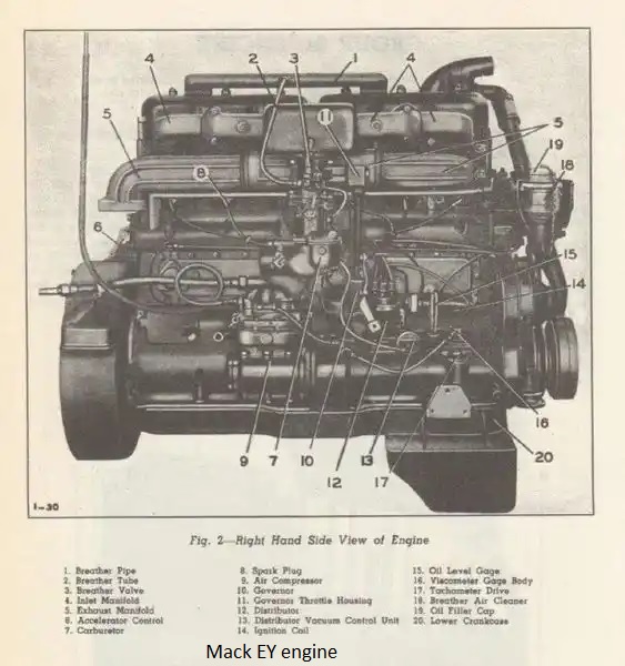
2 Likes
Well I would say that resolves the question. Problem solved.
Excellent find. Sometimes it’s a pain to find decent pic of any subject being worked. Ruck On!
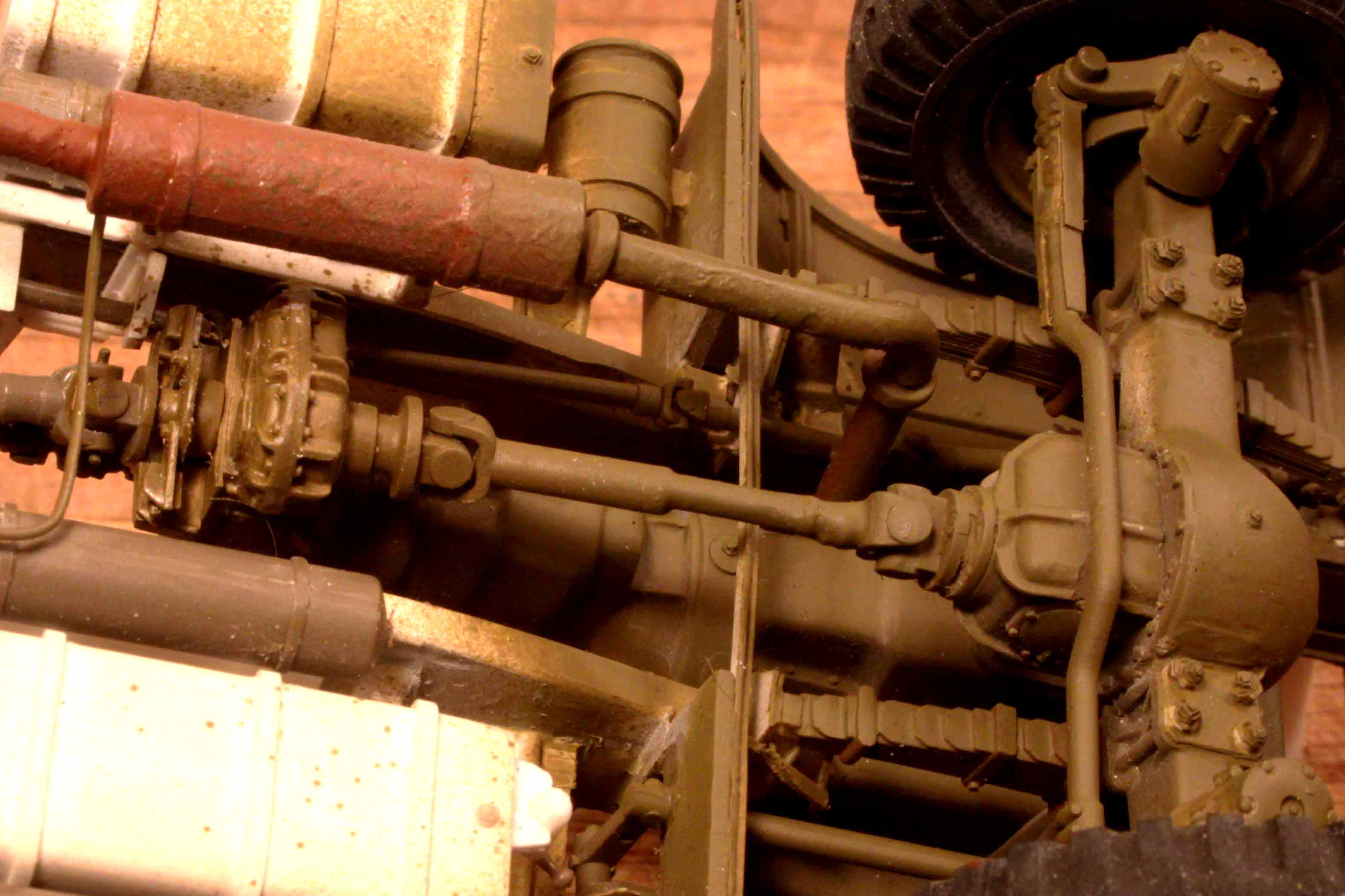
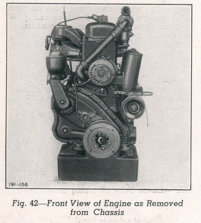
It’s also interesting that the air compressor is driven by the same shaft as the distributor.
(It’s immediately behind and below the updraft carburetor)
Most modern diesel air compressors are belt driven.
Back in the day it was common for multiple engine accessories to be driven on the same shaft. German engines of the day certainly. To this day many engine accessories of big Russian engines are GEAR driven directly.
p.s. I should have known it was a gas engine but the question just never came up until now.
Mike
1 Like
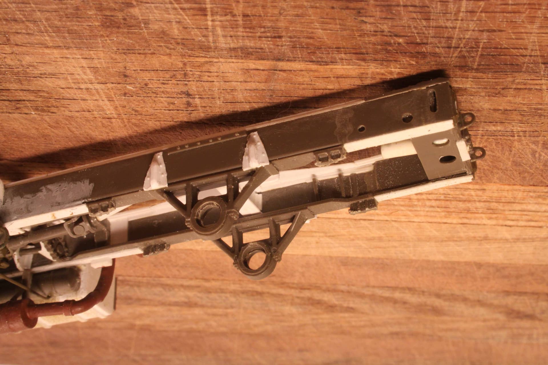
Perhaps we might take a little side trip here:
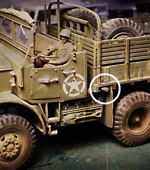
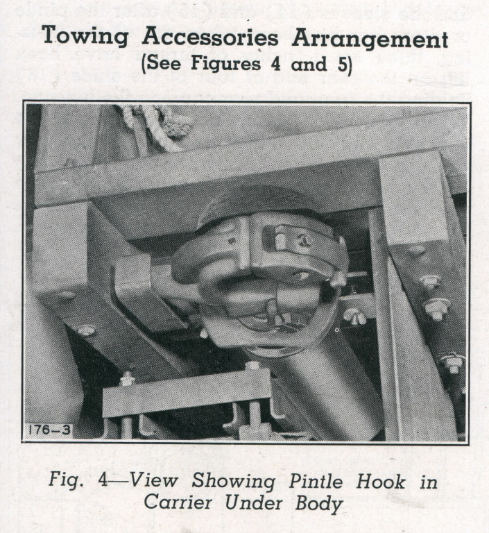
As we talk for a moment about that custom Mack designed hitch and the receiver it fits into. (The NO also carried a regular pintle hitch that could be exchanged for the gun hitch.)
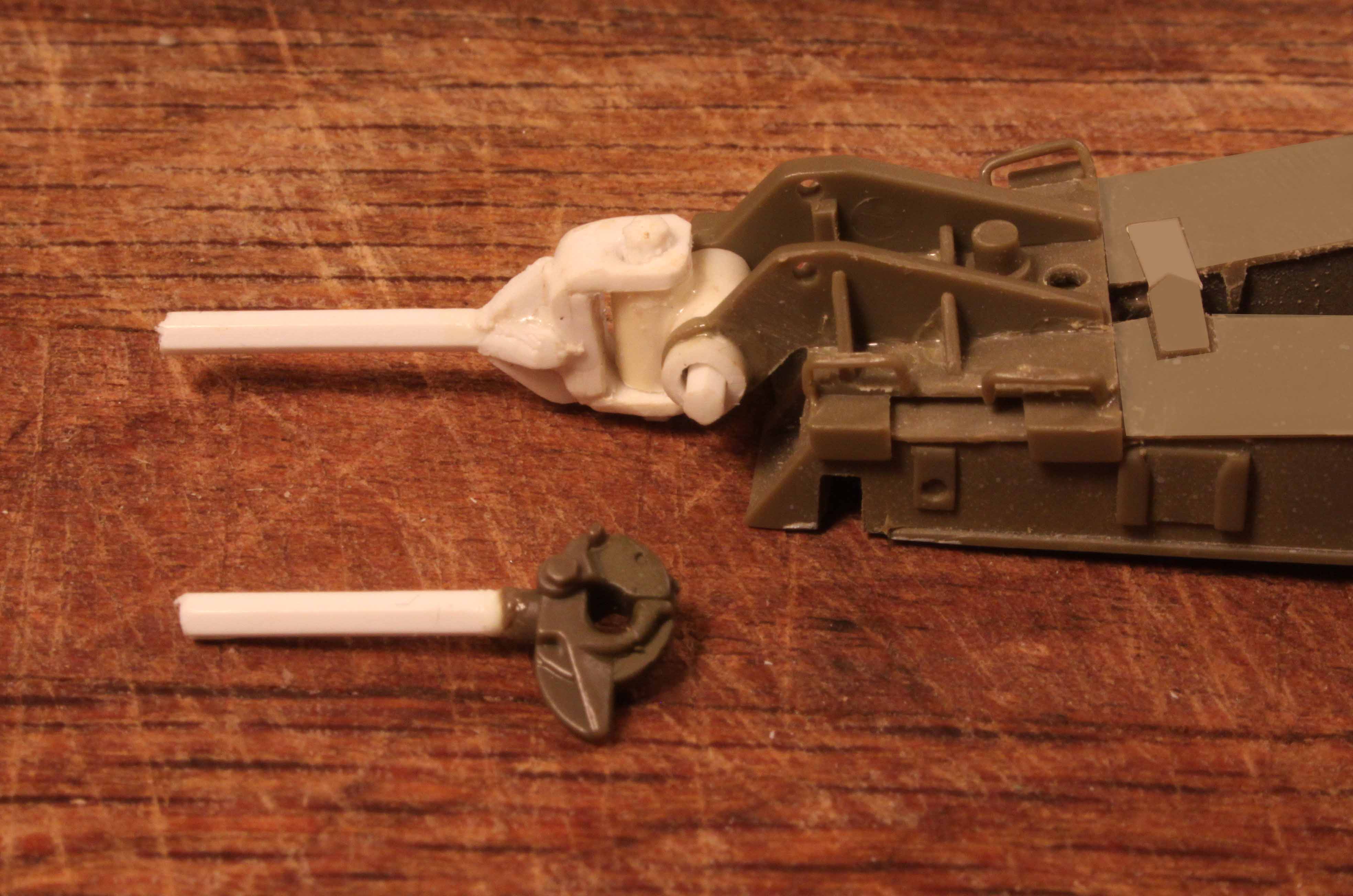
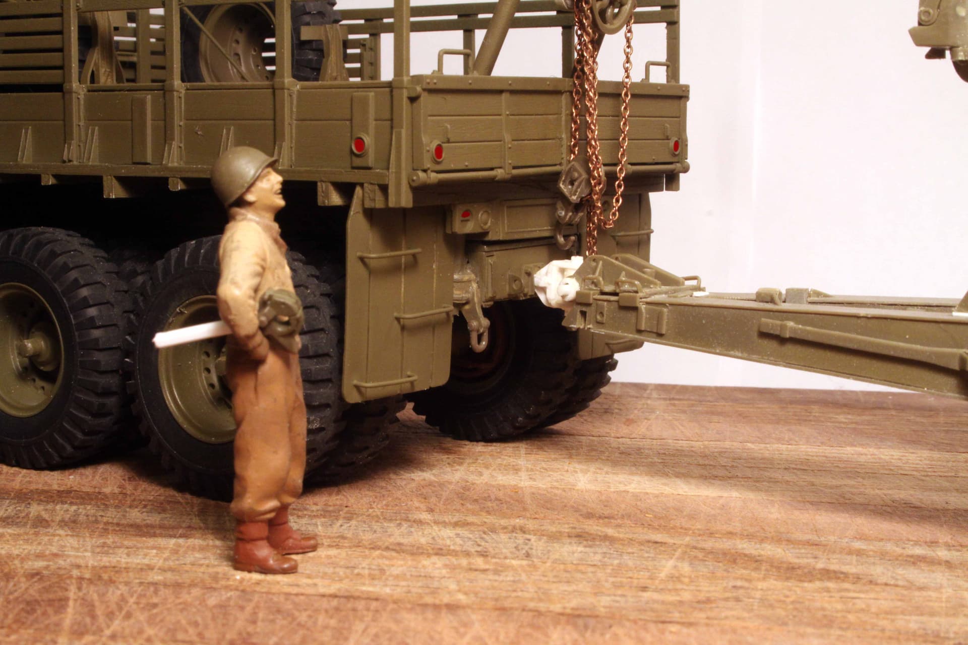
In this photo Sgt. Joe holds the smaller pintle hitch under his arm.
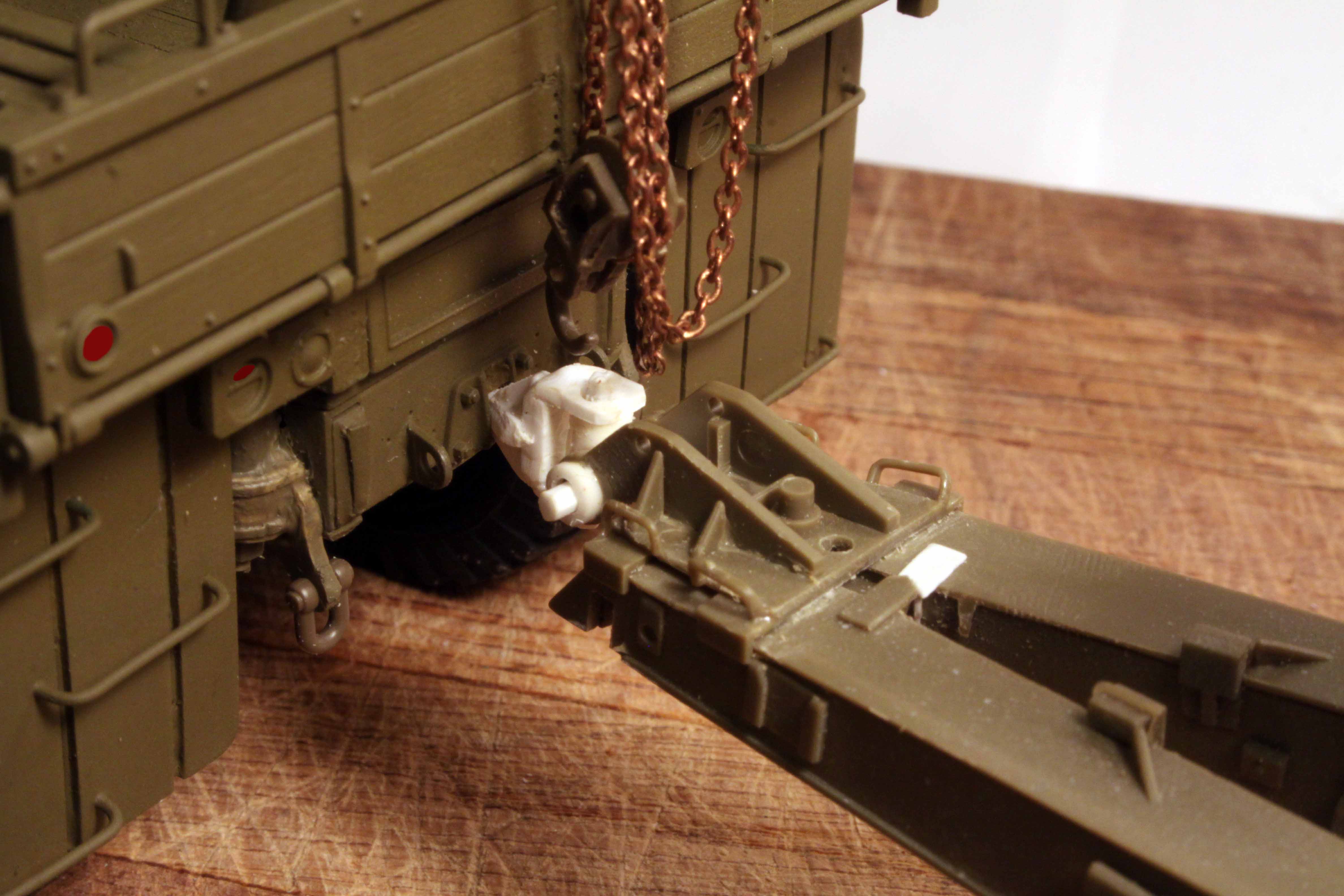
The Mack designed 'hitch" was nothing but a massive universal joint that would allow the towed gun to move and rotate in any direction relative to the Mack tractor.
My hitch “receiver” mounted within the truck rear frame is just a piece of small diameter Evergreen tube. However I found that the proper size round rod too easily slipped out of this tube. I therefore substituted a plastic hex shaped rod with a tapered tip for the shank of the hitch as this fit much more tightly into the receiver tube.
Note: the much smaller standard pintle hitch was carried under the front right corner of the load box right behind the cab. I have installed a second receiver tube there so that this pintle can be stowed just as on the real vehicle however this pintle remains removable and can be installed at the rear of the truck when necessary.
2 Likes
That’s all beautifully detailed work you’ve done.
1 Like
Excellent work, but Sgt Joe is a bit weedy for a guy who can tuck that big lump of steel under his arm! Should look more like Arnie if he’s pumping that much iron… ![]()
1 Like
One more closing shot of the gun hitch:
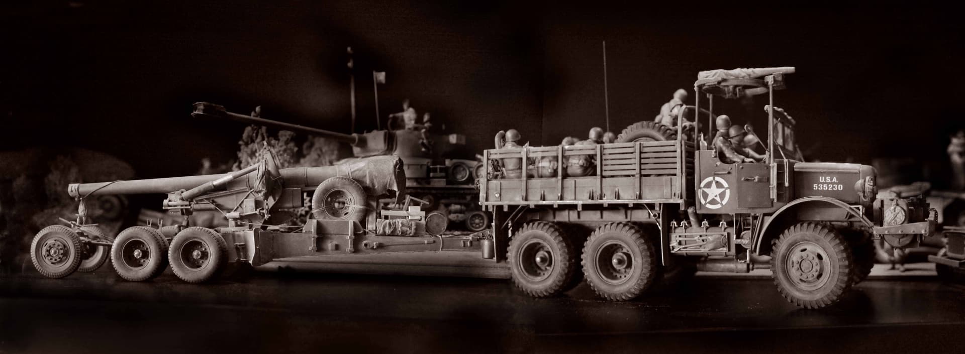
Some people have theorized that the pintle hitch on the rear of the gun was for towing an ammo trailer. In reality that rear bogie would never be strong enough to take the pounding of towing a loaded 4 or 8 ton ammo trailer.
The real purpose of the rear pintle was for towing the M1 or M5 Limber when not needed by the Mack.
While the Mack does not require a Limber, the next vehicle assigned to relocate the gun might be an HST or Diamond T which WOULD require the use of the limber. Therefore the Limber still needed to be towed along.
Early M1 Limber with large screw jack for lifting the gun trails in to travel position. (PSP Resin model from Scale-Link in the UK)
M1 M1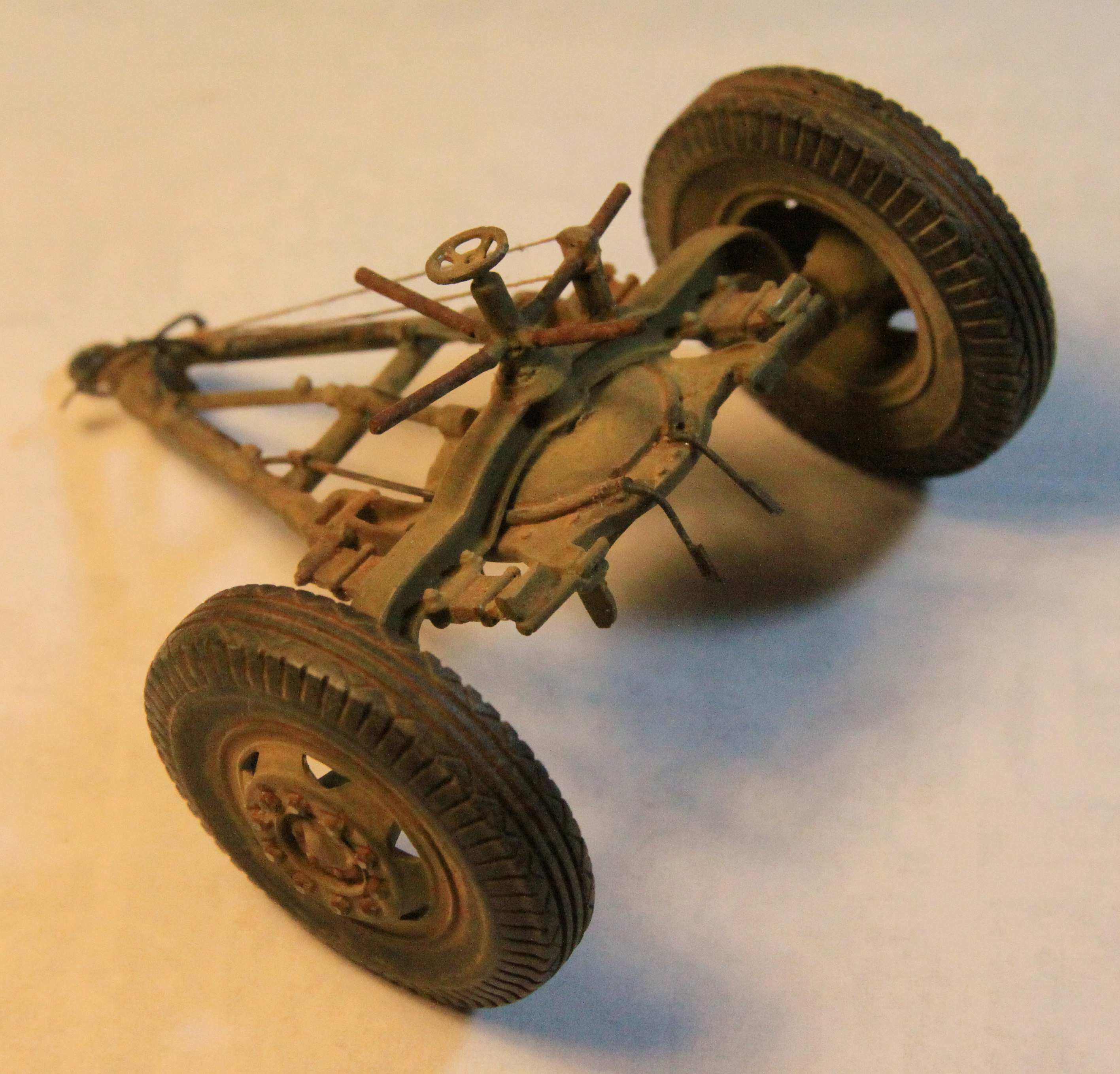
Later design M5 Limber (AFV Club) with Sgt. Joe demonstrating its’ use here with the M23 8 ton ammo trailer (Work in Progress)
M5 M5 M5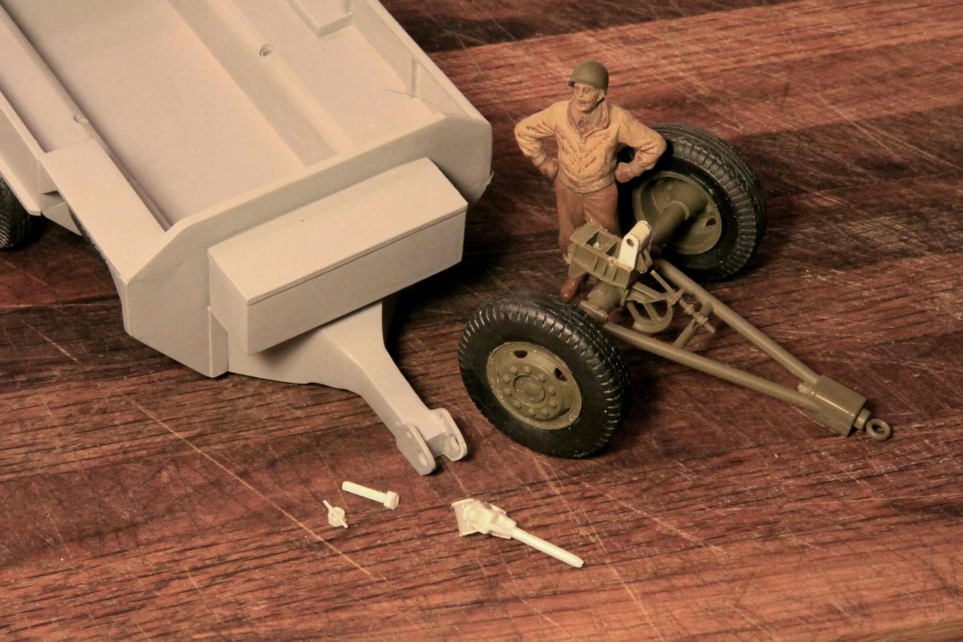


2 Likes
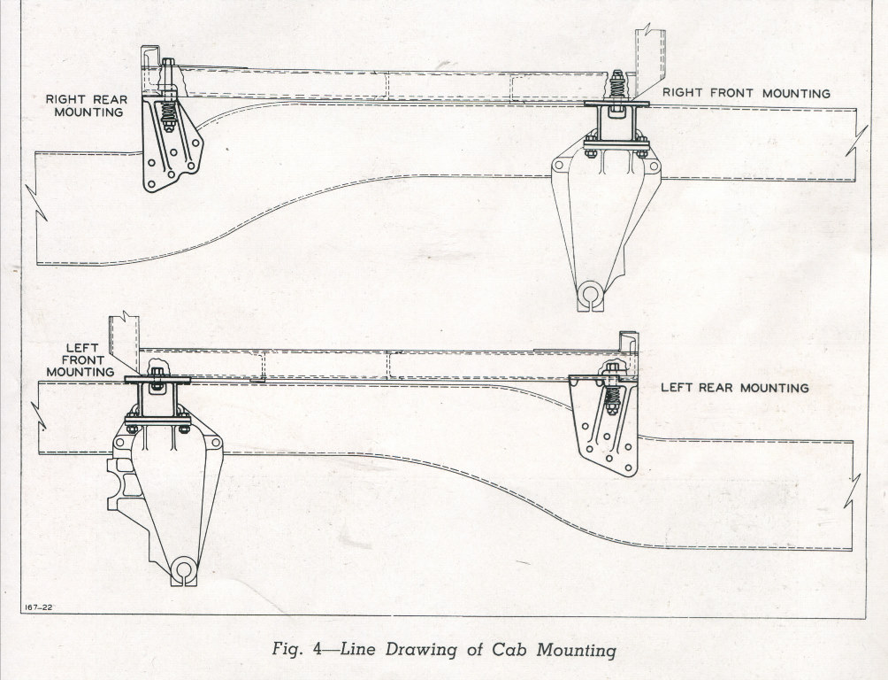
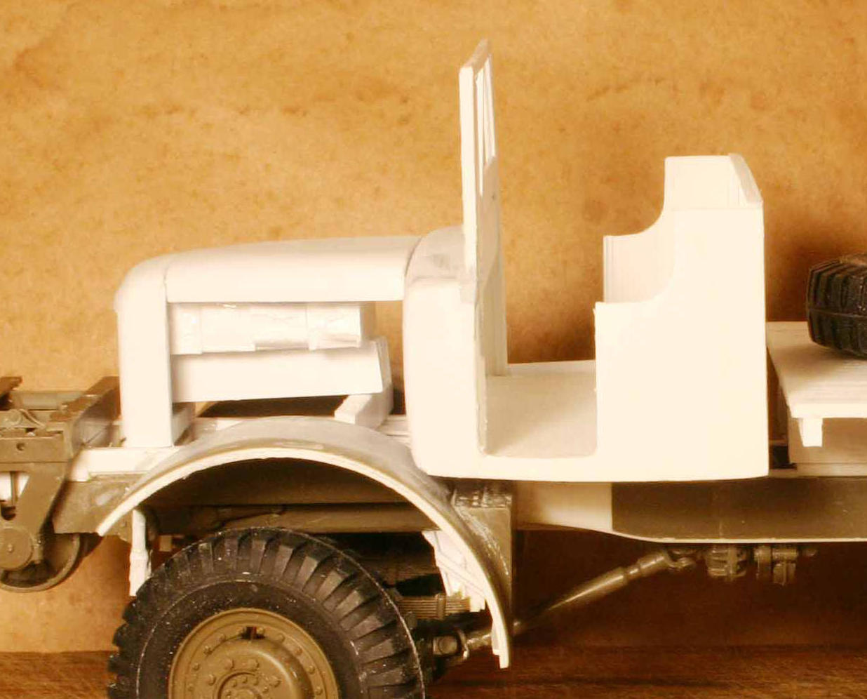
Time to Start on that Cab:
Like so many other aspects of this build the cab started out too tall. I had to cut down the windshield once and that rear wall of the cab at least three times.
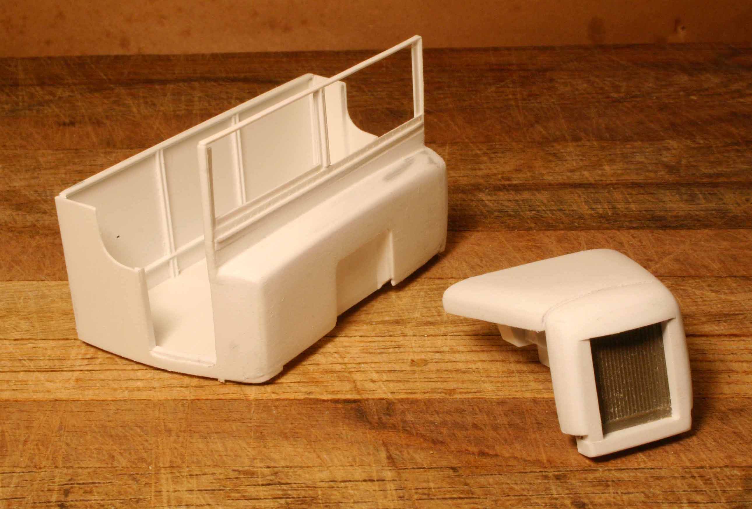
All the curved surfaces here were formed with built up solid forms of plastic then sanded to final shape. This includes the radiator surround, the curved hood and the cowl below the windshield. All else was done with plastic sheet reenforced with Evergreen shapes.
That radiator is a cut down portion of the Dragon Wagon piece
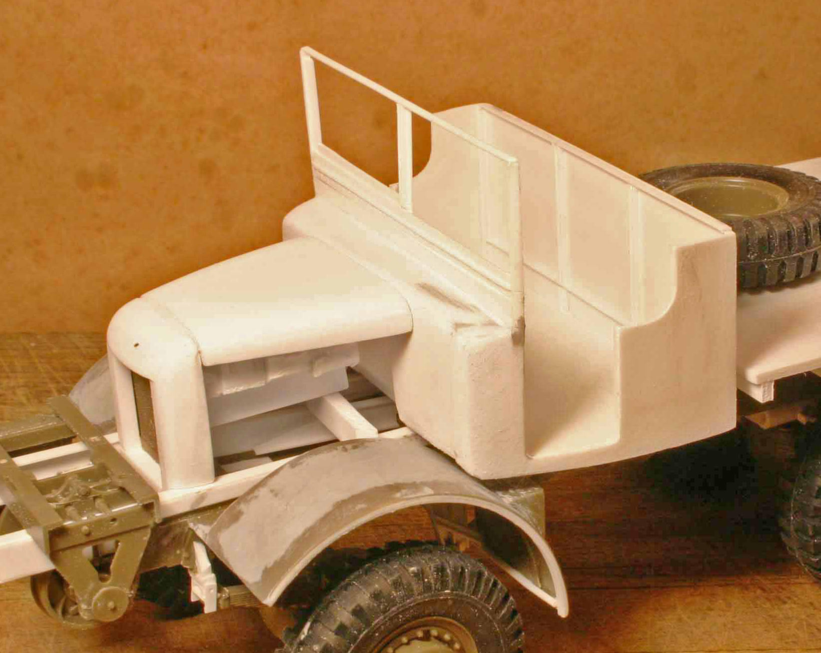

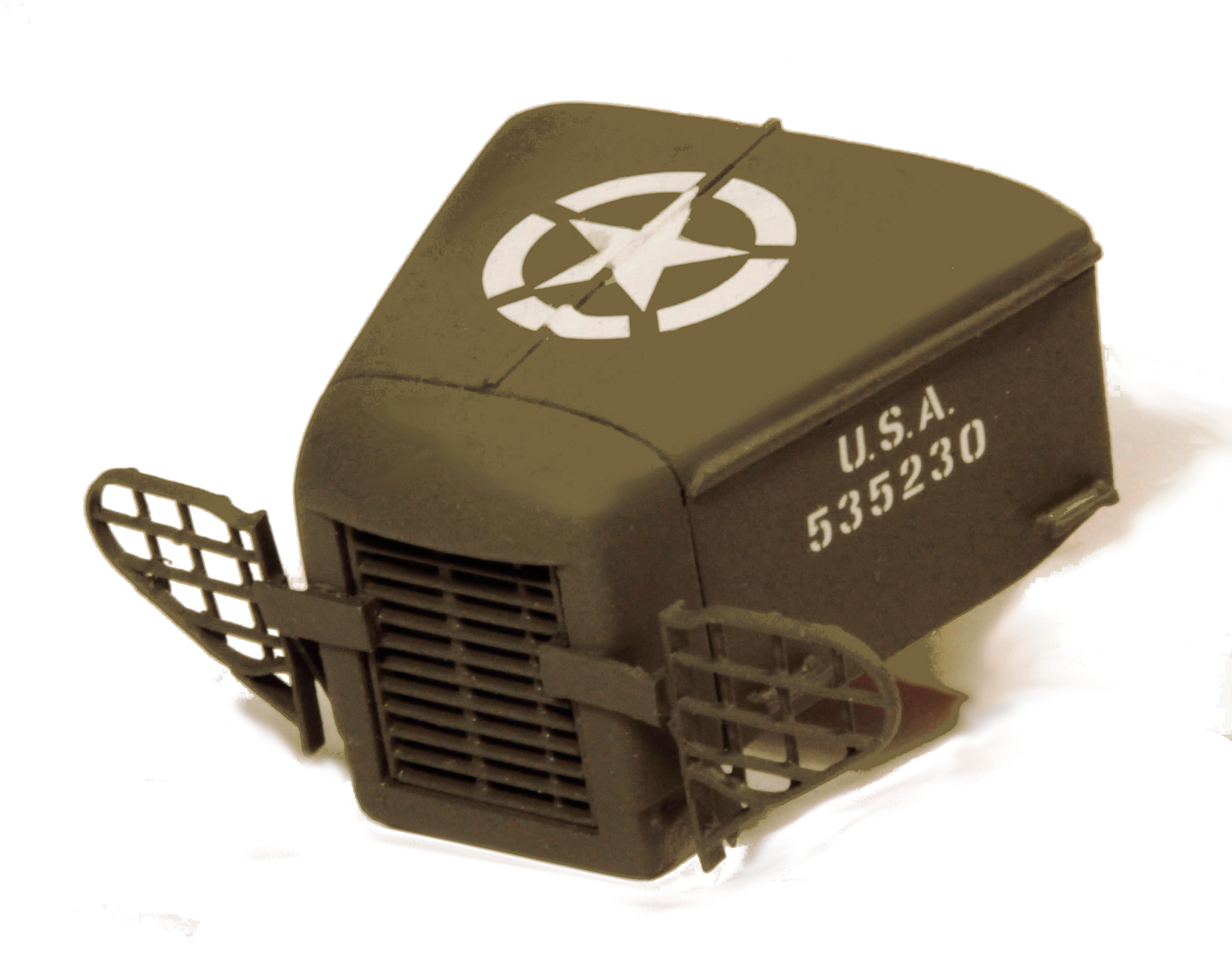
The headlight grills are actually the grills off the Dragon Wagon just rotated 90 degrees and with additional plastic cross rods added.

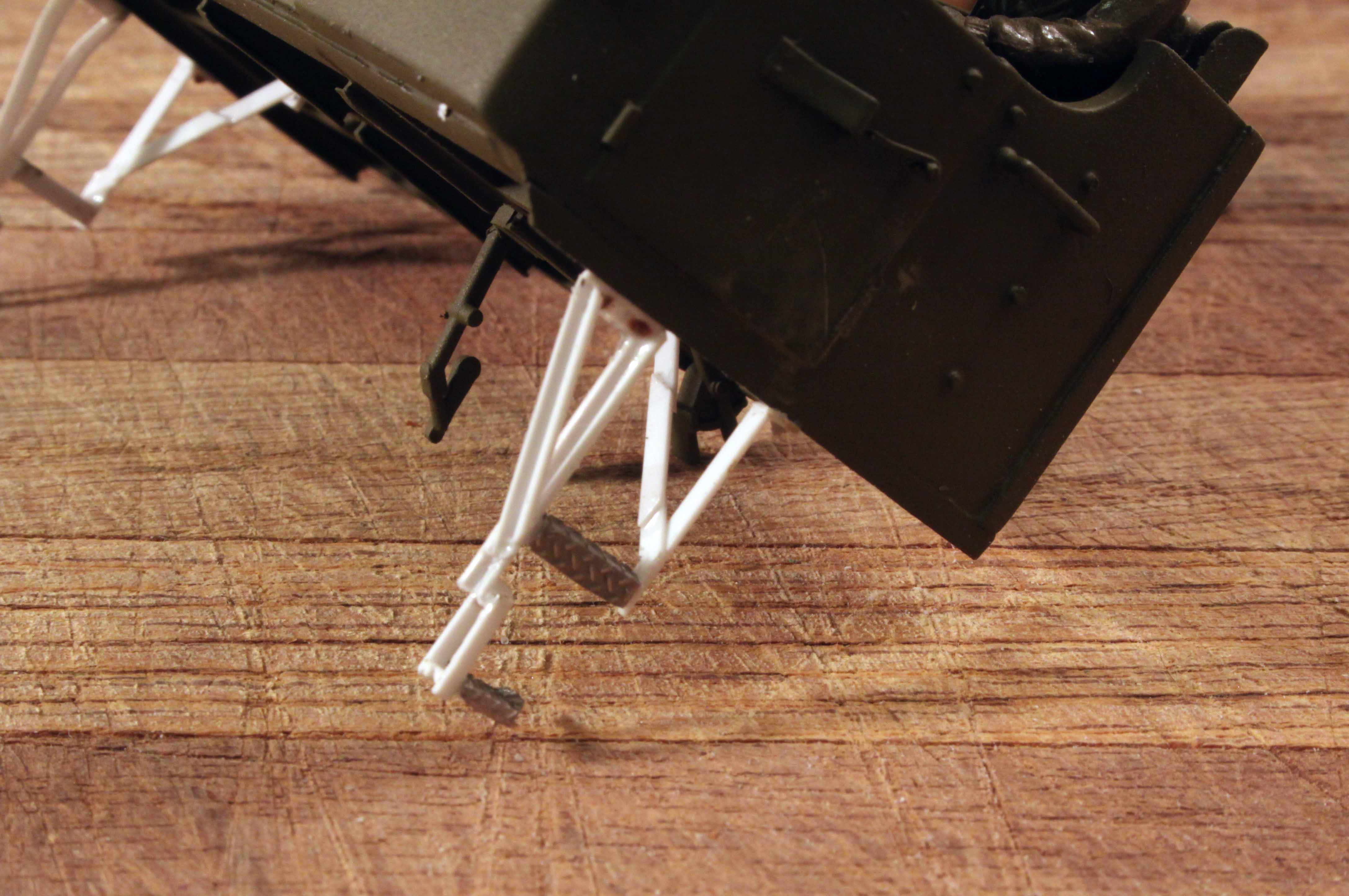
With just a little glue and some pressure you really can weld the rather soft Evergreen plastic into a single piece assembly such as these cab steps.
I have butt welded truck frames (model) using this technique without the need to add reenforcing splice plates.
5 Likes
Yep, spark plugs and wires are a big giveaway!
Ken
1 Like
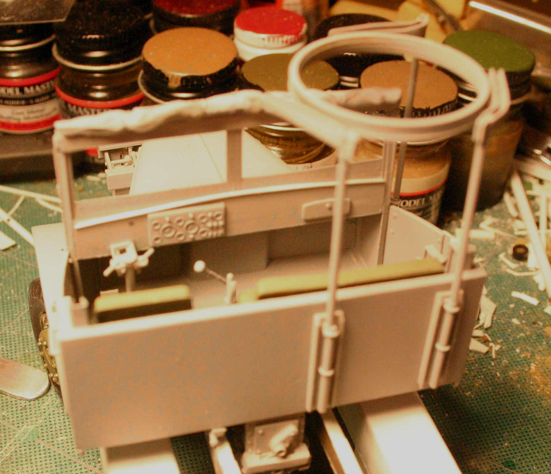
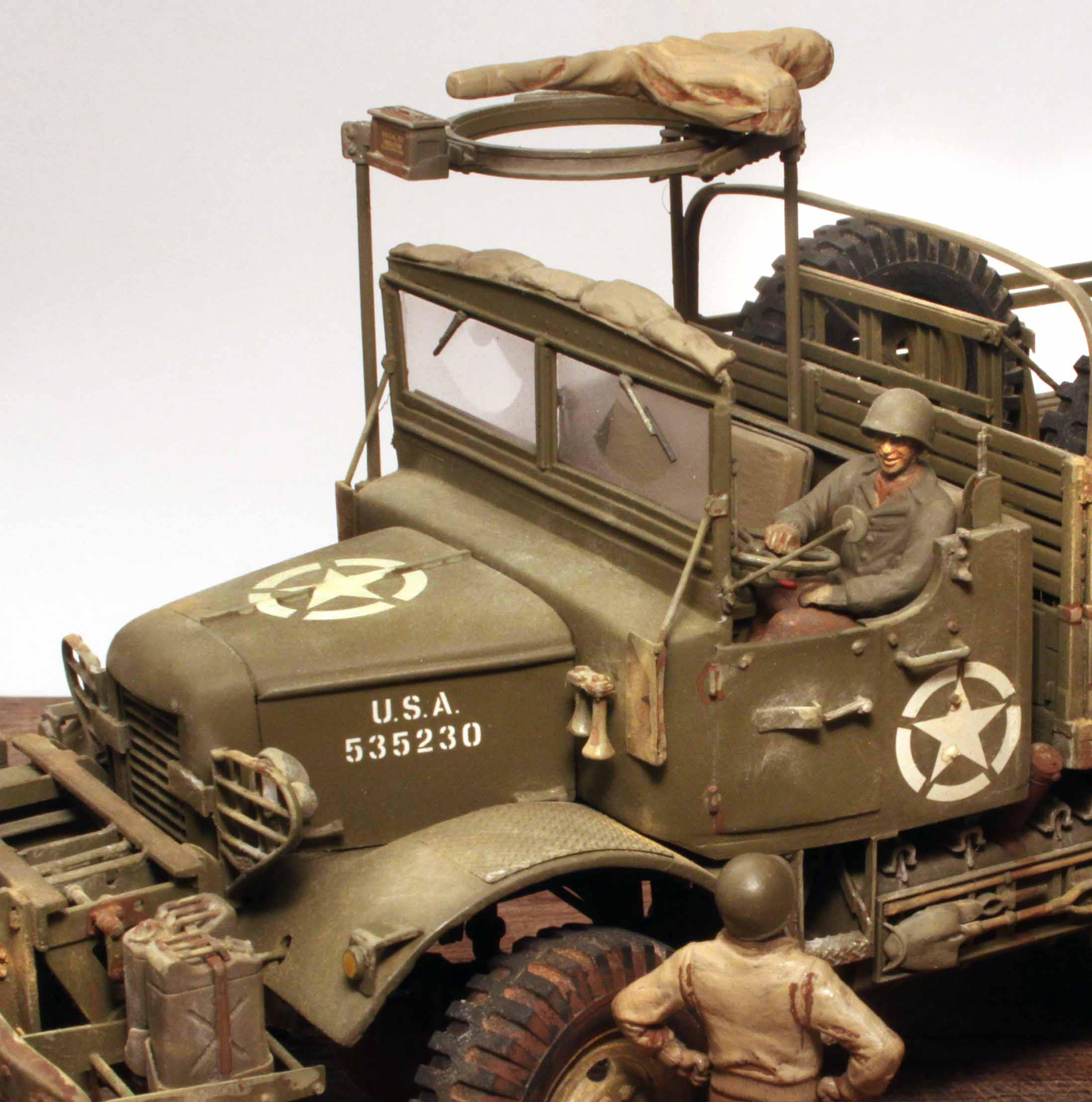
And Now How About That Cab Interior!

From the TM
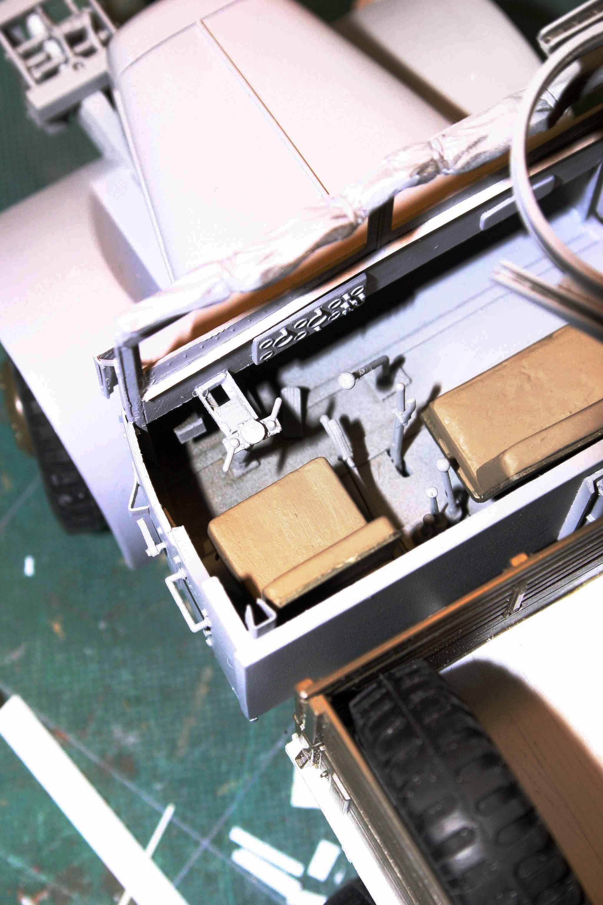

I did cheat and simply lifted the instrument cluster out of the Dragon Wagon, sanded it as thin as possible and mounted it on the cowl panel.
The other shifters and quadrant levers came from either the DW winches or from my collection of CCKW spares. The steering column and steering wheel come directly from the DW.
The cab seats are actually the two seats out of the Tamiya CCKW open cab. I sectioned one to be narrower for the driver’s seat and then added that section to the middle of the other seat to make the right side double passenger seat.
As to the gun ring, it is the standard after market Tamiya gun ring for the CCKW. However only one vertical leg matched the format used on the Mack so rather then scratch build the other two, I just took the easy way out and bought 3 gun ring kits and the rest of the parts fed into my spares box.
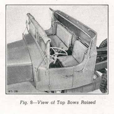

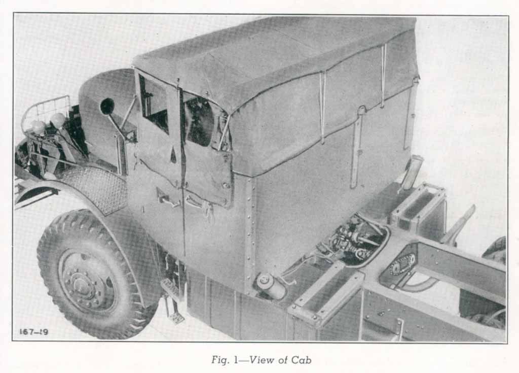
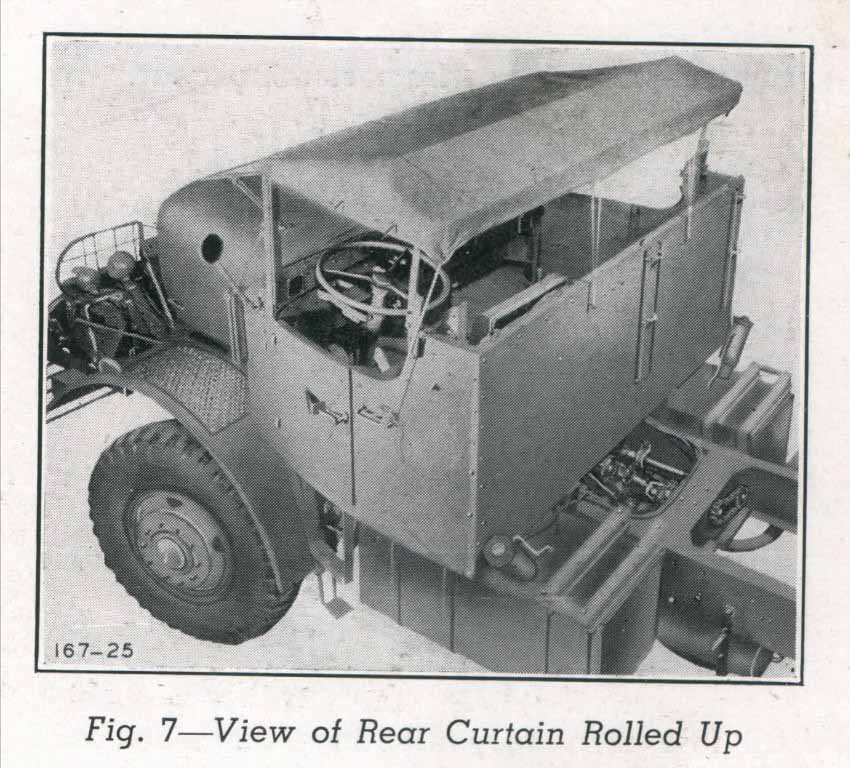
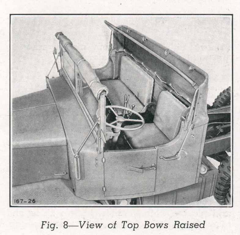
The canvas for the cab was a two part affair with the main part of the roof being stowed above the windshield and the rear canvas folded down behind the seats. (I do one day intend to fabricate the top support ribs and the back wall of the canvas.)
2 Likes

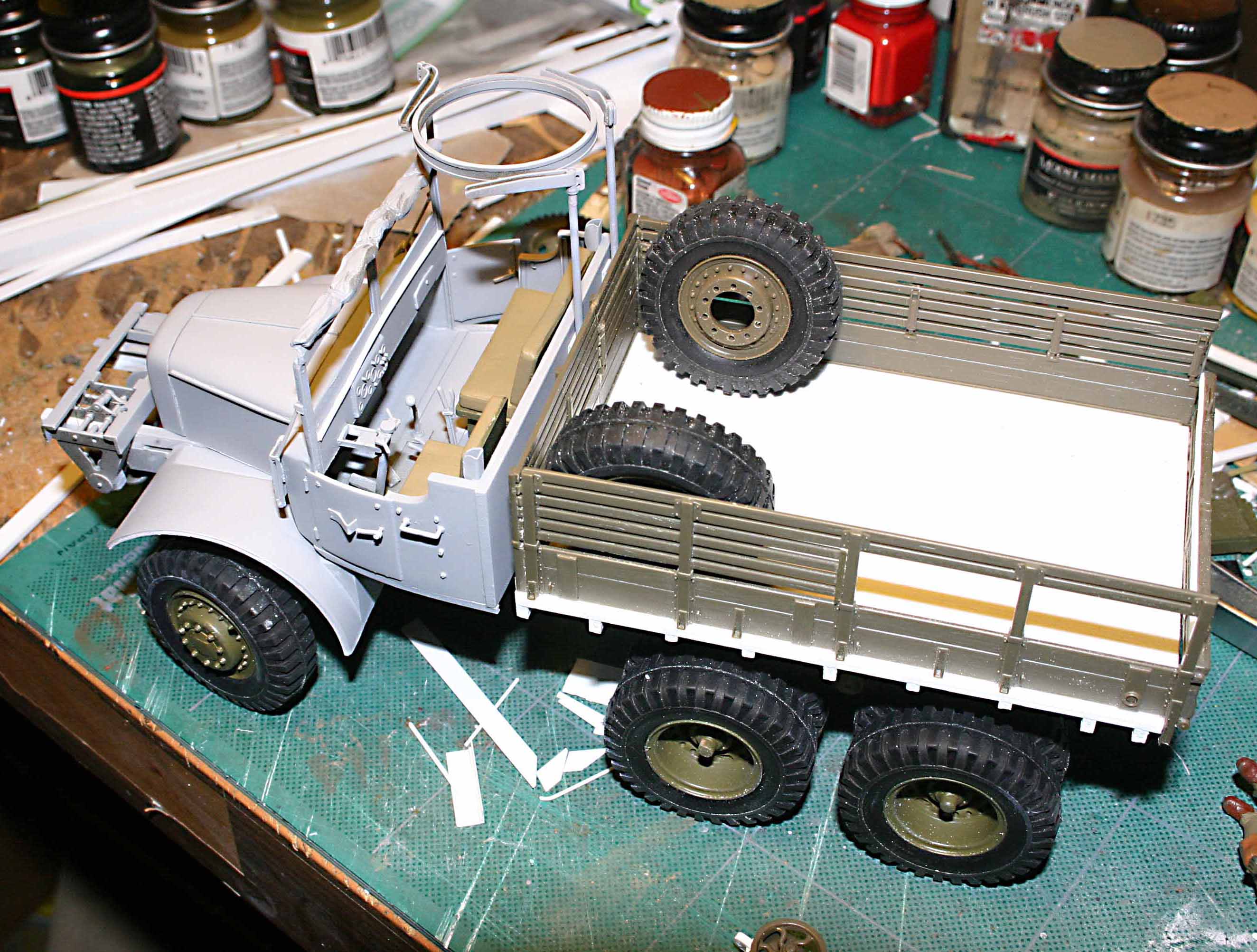
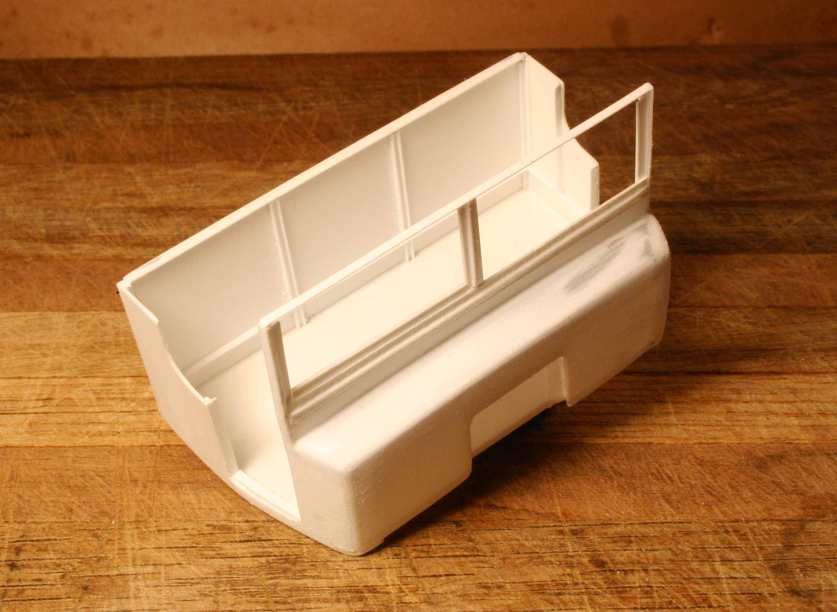
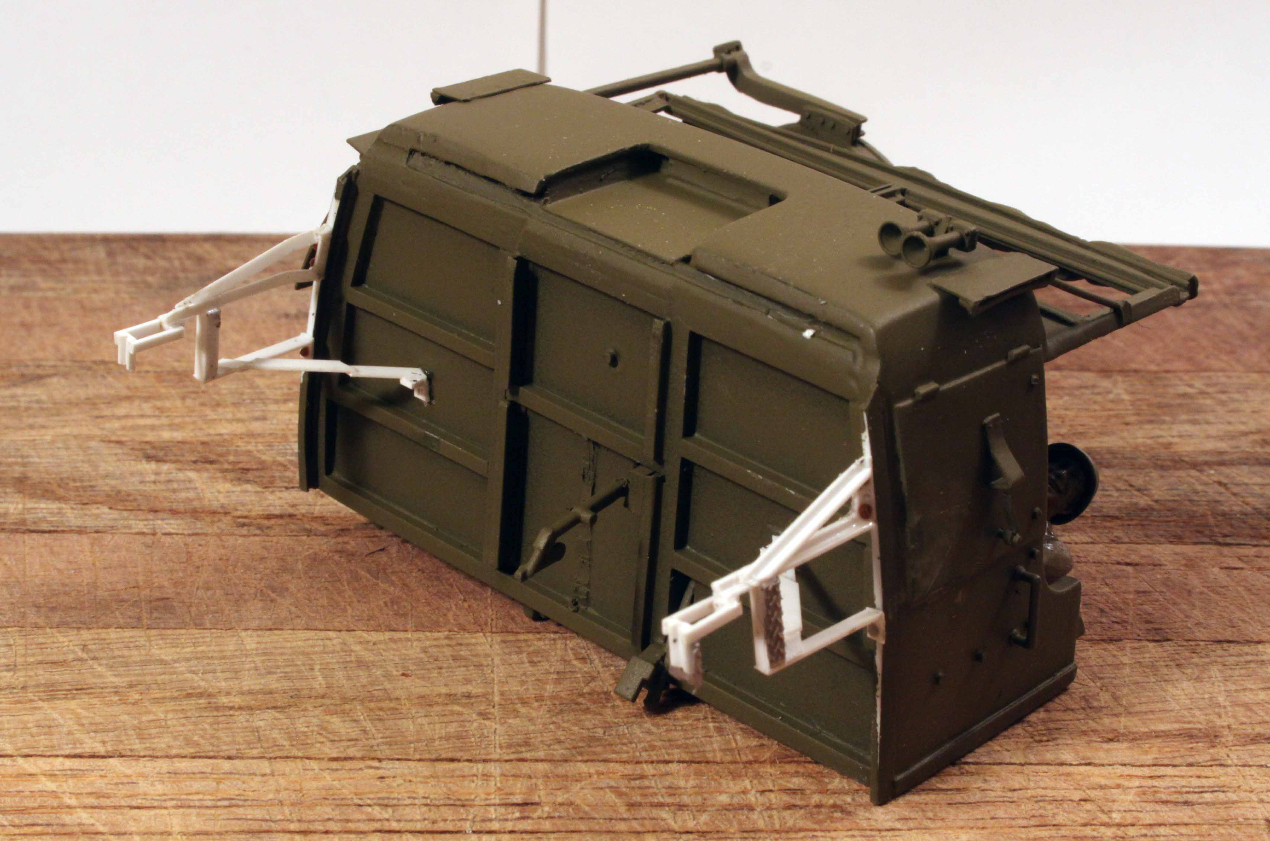
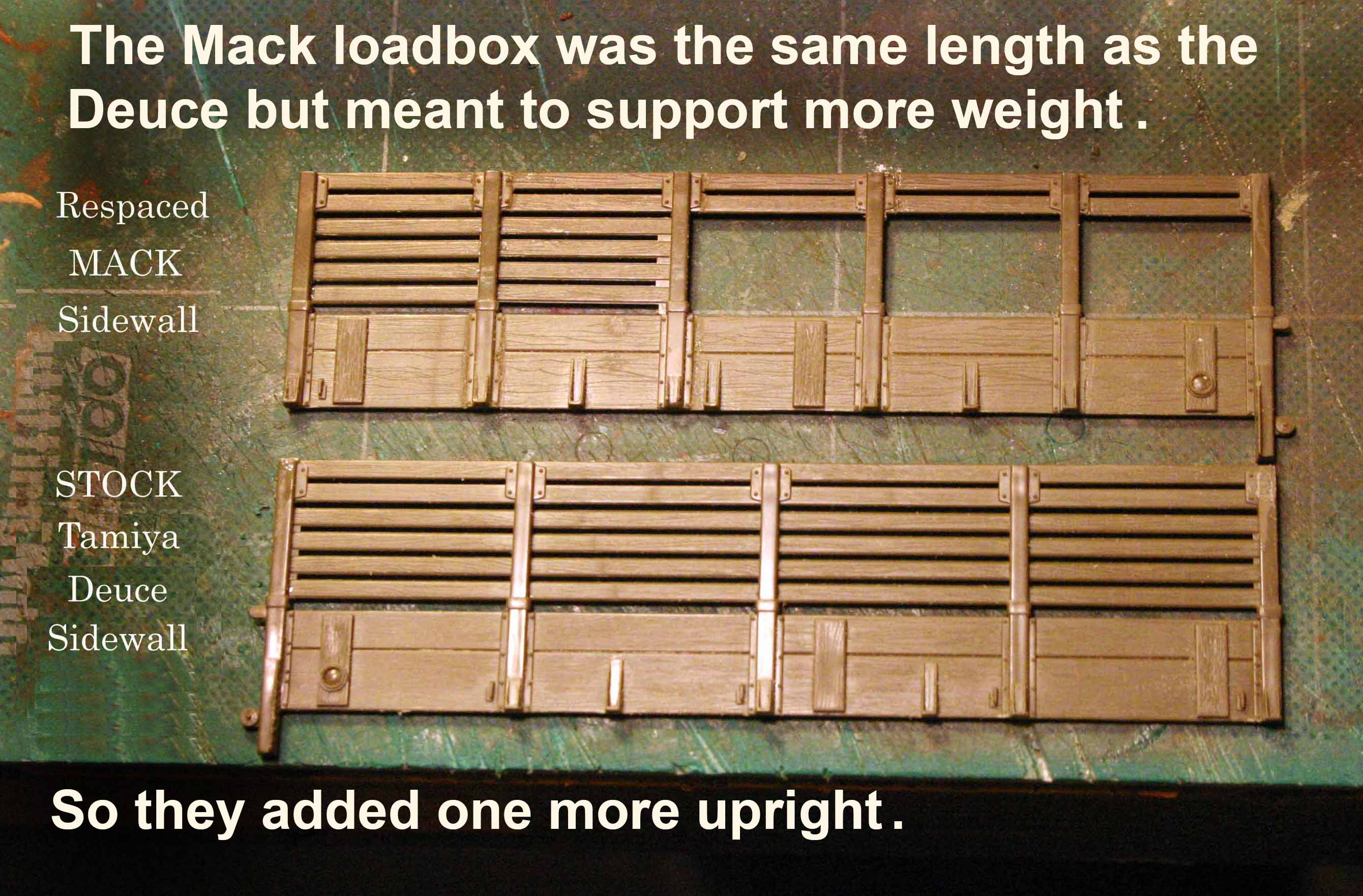
The Wooden Loadbox for the Mack was Built by the same sub-contractor that built the load bodies for the GMC, Deuce and a Half.
Therefore the Hardware and Construction style will be the same as on the Tamiya model of this truck.
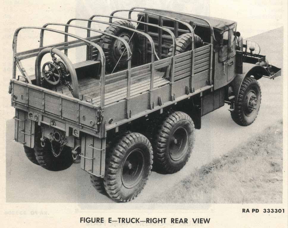
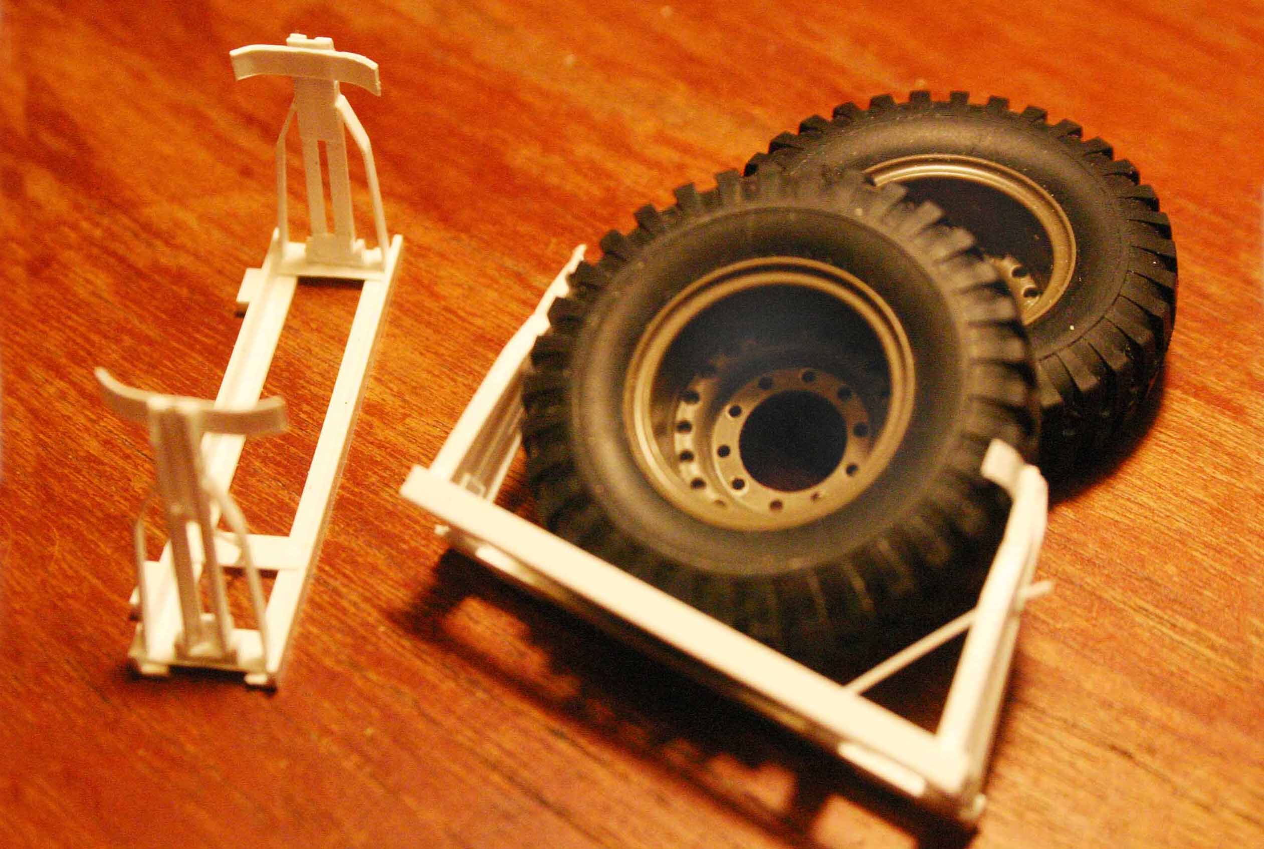
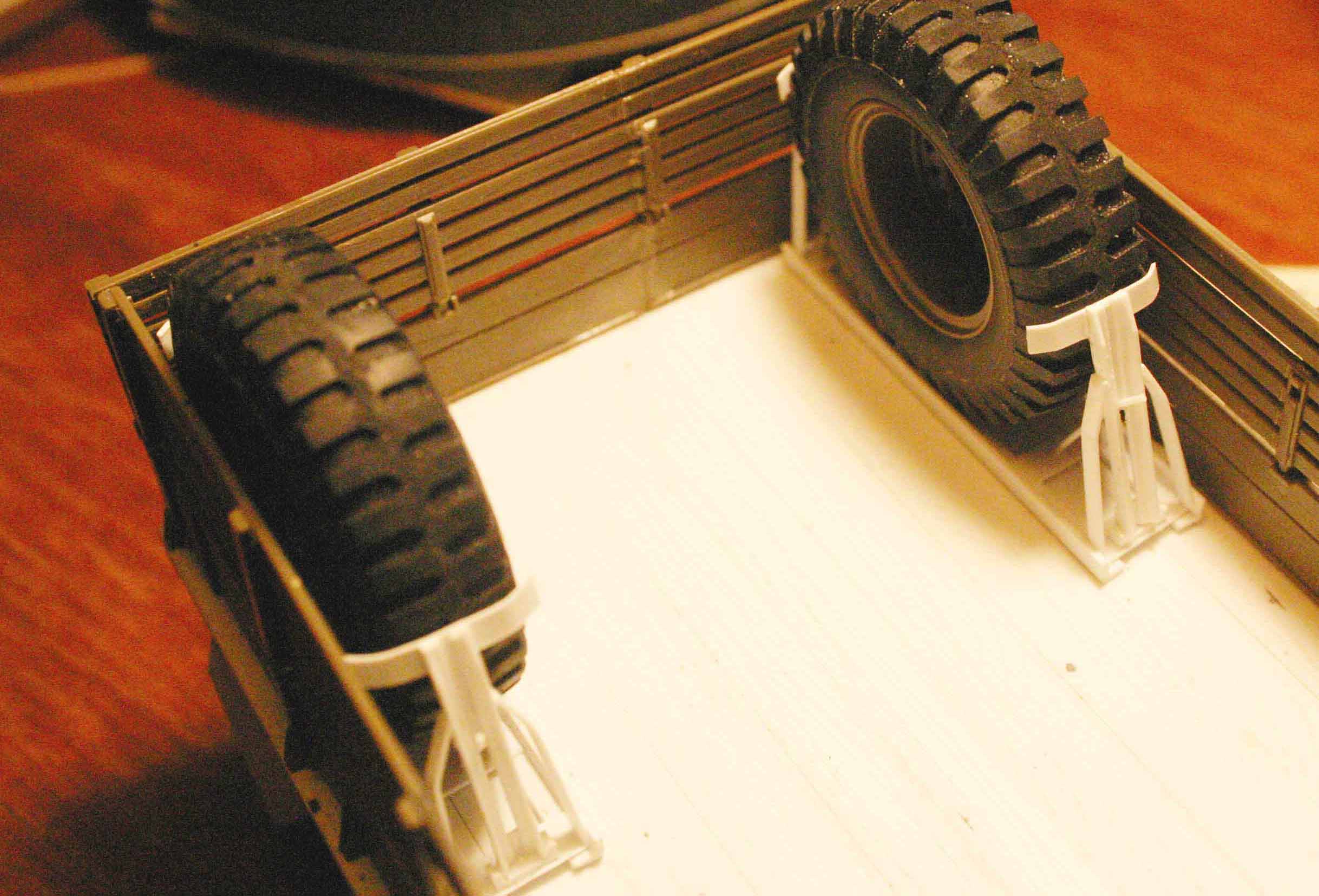
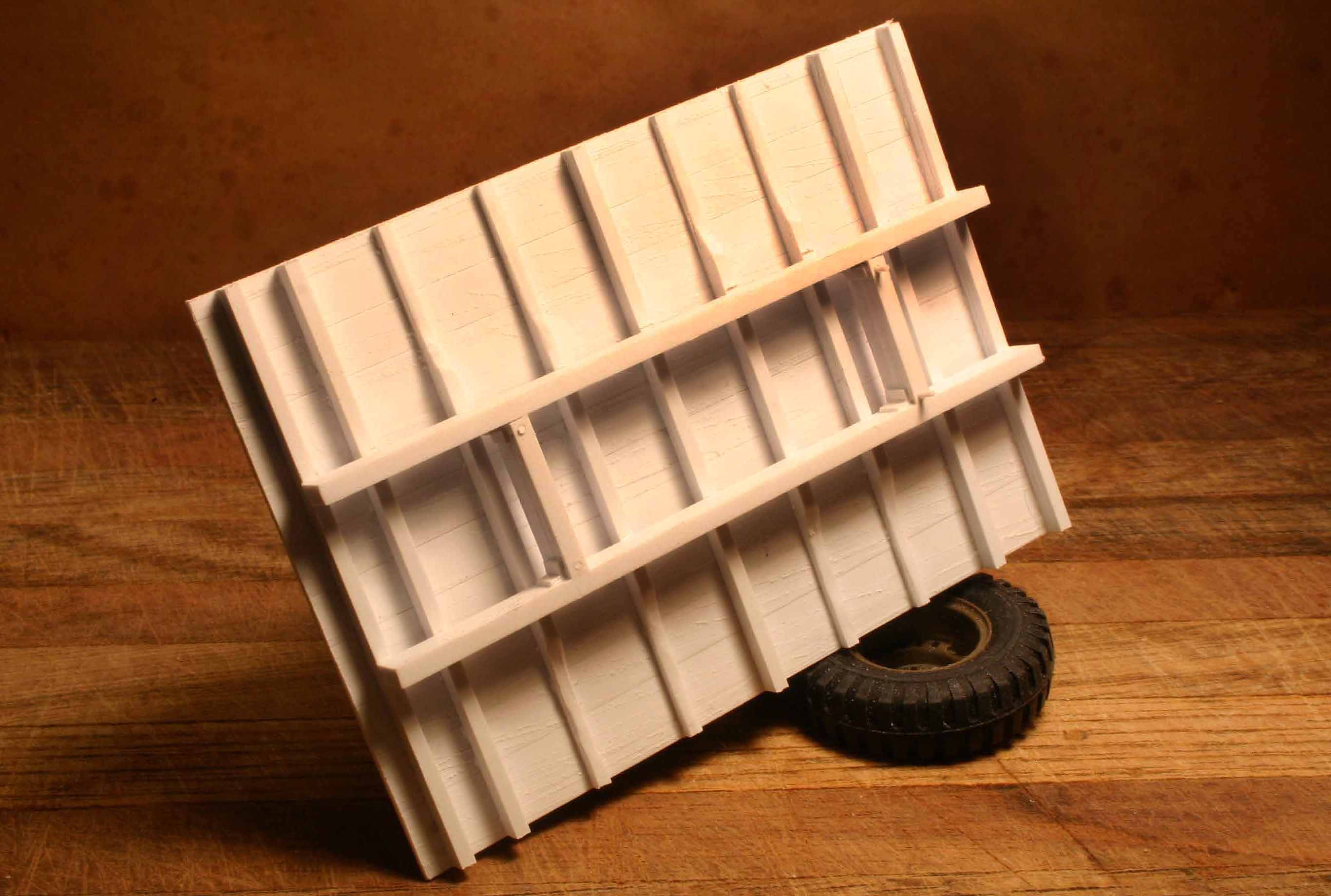
The loadbox for the Mack was wider but basically the same length as the box for the Deuce. However the Mack was expected to carry more weight so the side fencing was built with six vertical uprights rather than only five as the Deuce. This made for some interesting “cut and paste” to remodel the Deuce fencing. Also the troop seats only ran the last three bents to all for the two spare tires. One on each side.
The vertical cuts made with the jeweler’s saw were not behind each vertical post but behind the small metal brackets that attach the vertical post to the horizontal fencing,

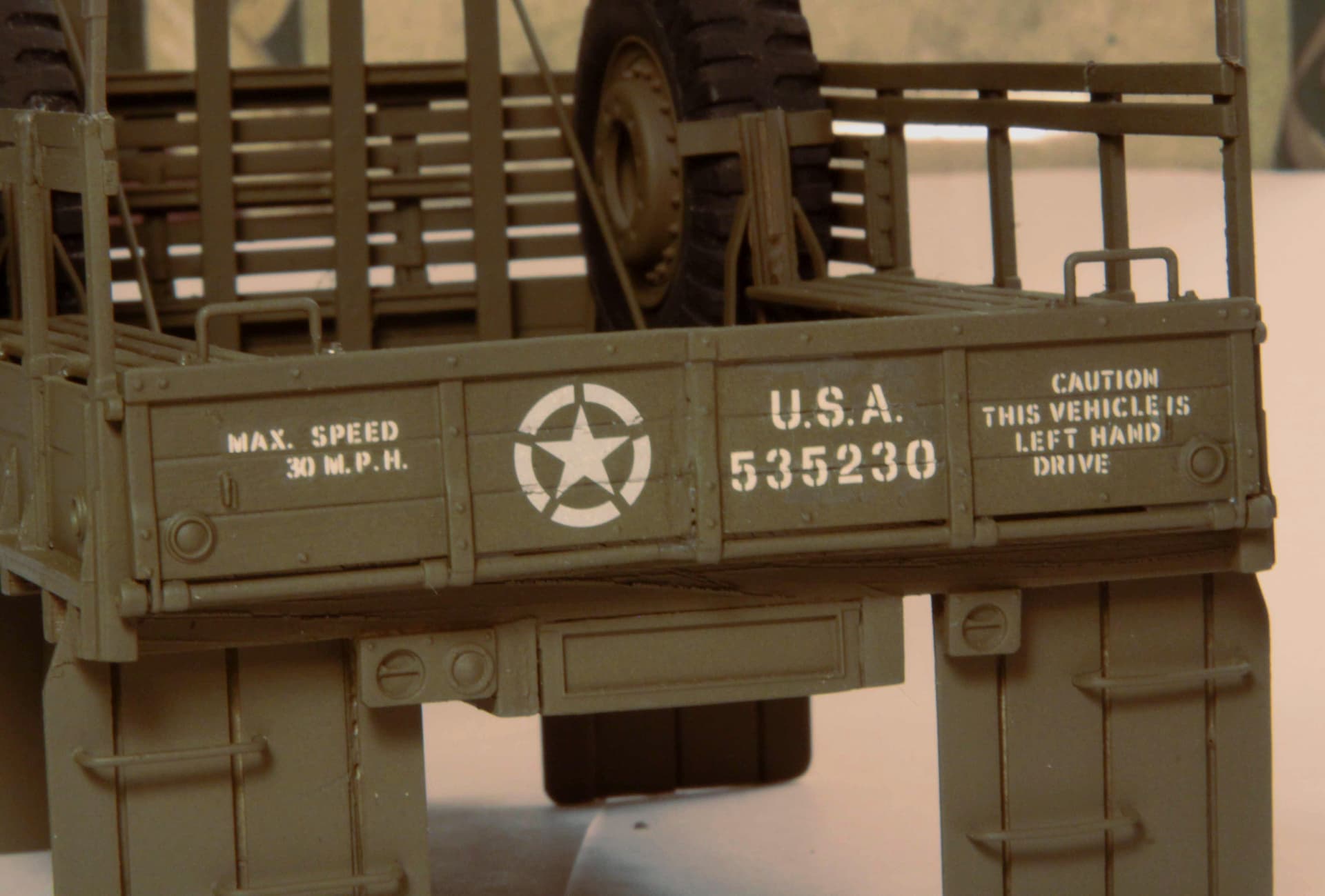
I did a similar “cut and paste” job sectioning the Mack tailgate as well as the front wall of the loadbox, building both from Deuce parts.
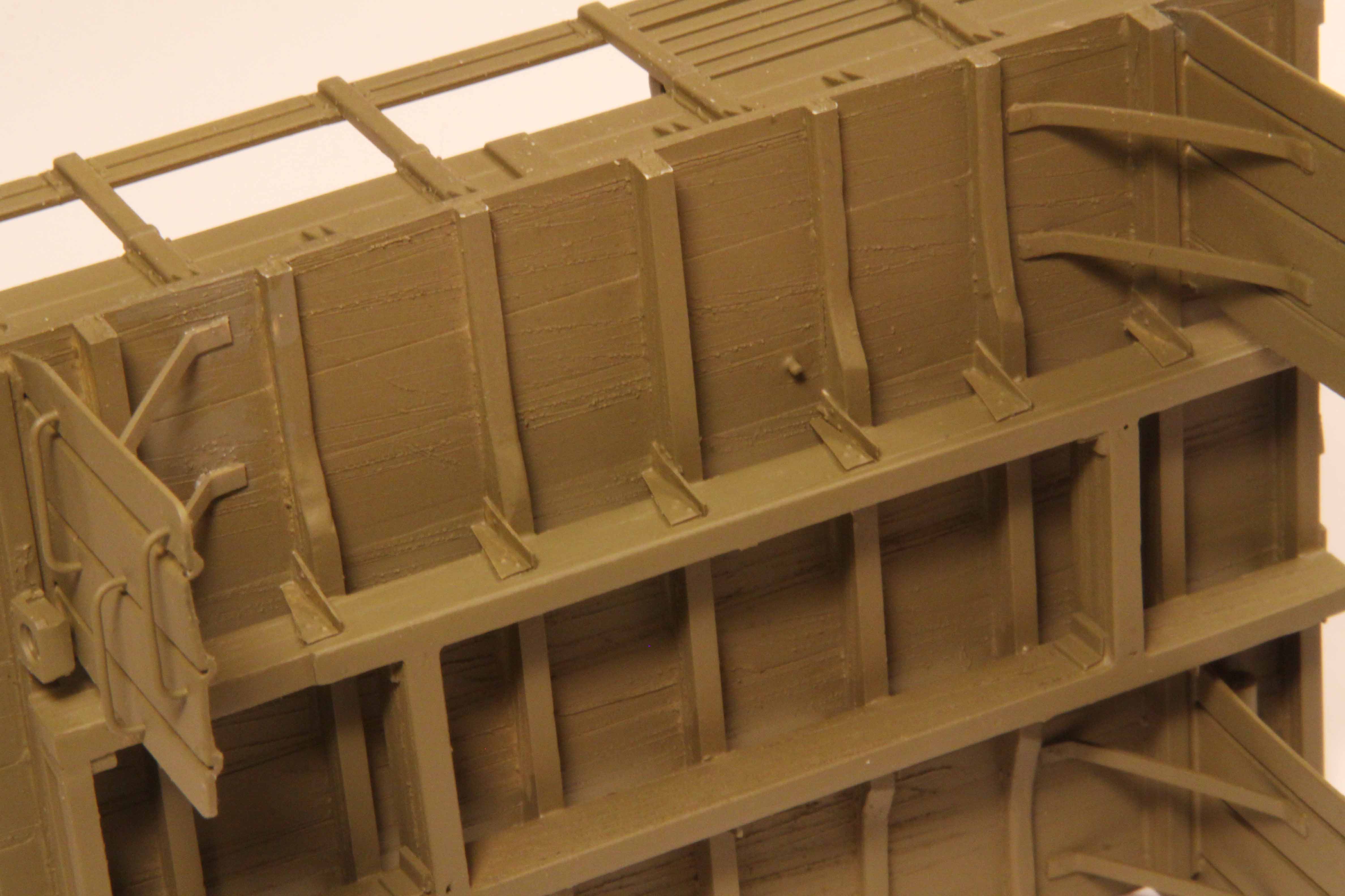
The underbody required some detailing as well.
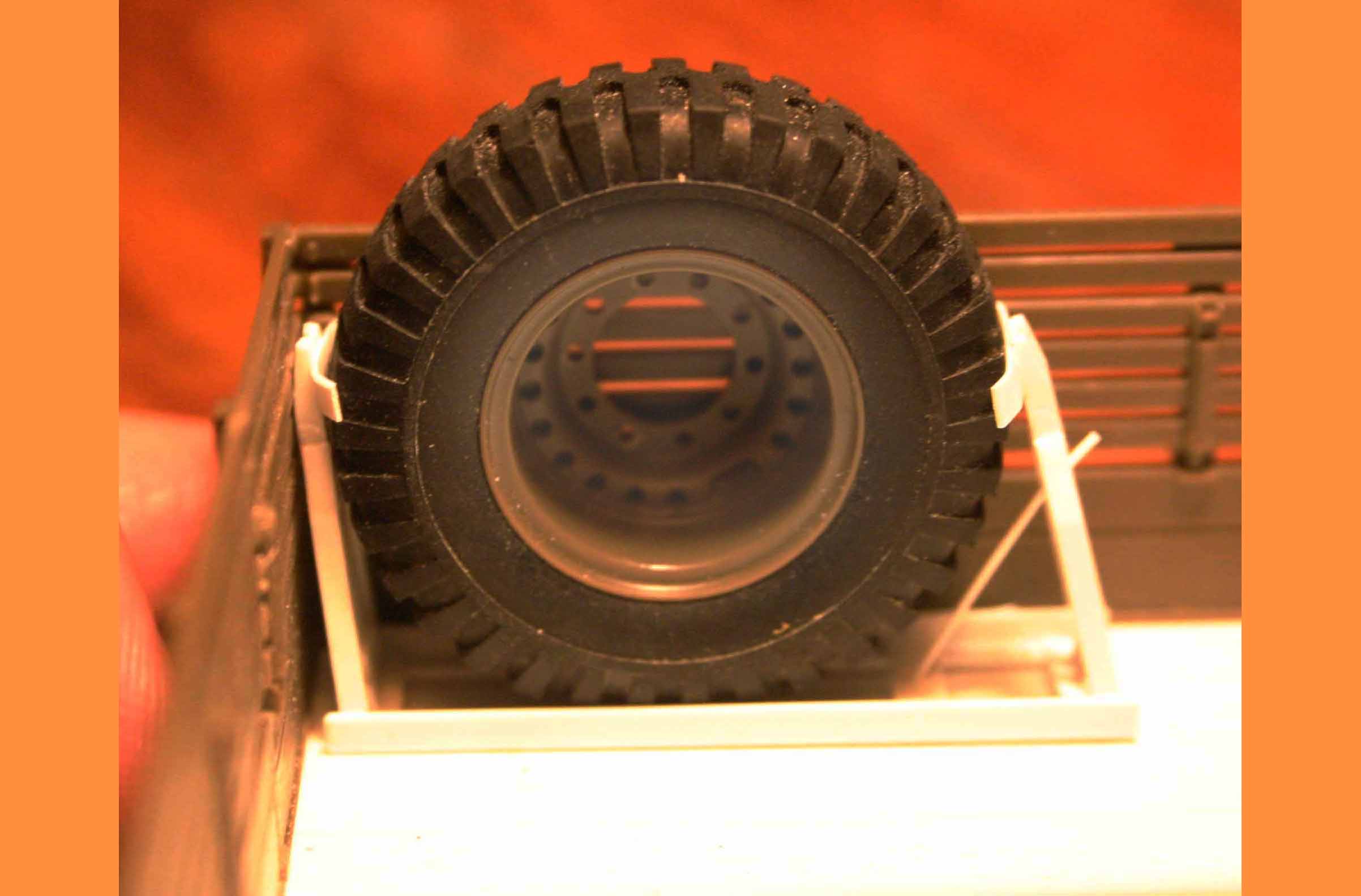
The “headache rack” seen between the two spare tires was just a simple grid built up using Evergreen “U” channel and “ell” stock. Then braced to the floor,
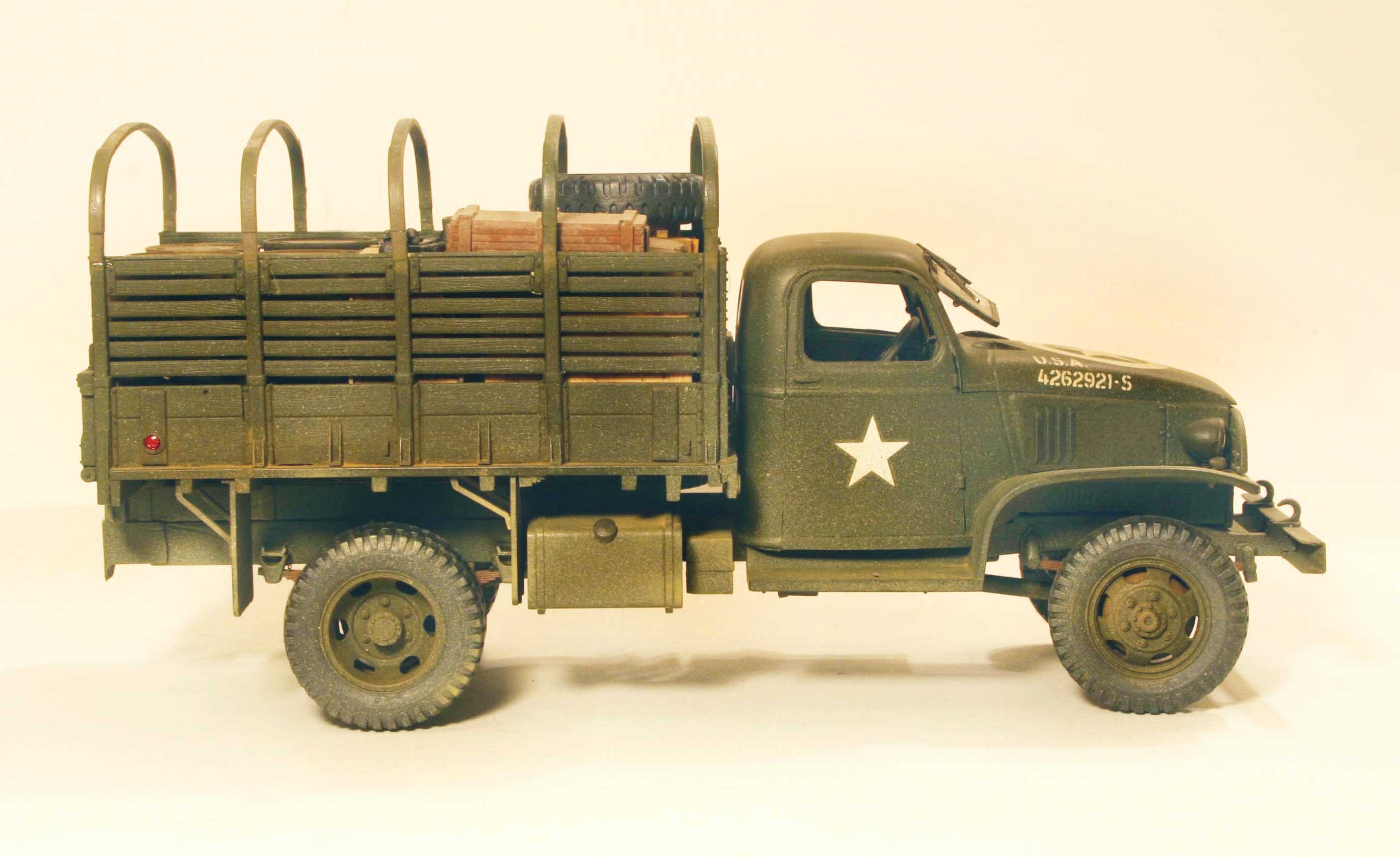
As practice working up the challenge of the Mack loadbox here is a shortened Chevy 1 & 1/2 ton truck built out of a Tamiya Deuce and a Half with the addition of a Italeri hard cab. (Done way before such models were available commercially in 1/35th.)
5 Likes