Meng Bradley BUSK III Start-to-Finish

For a complete build will all the gory details you can check it out at FSM’s forum here:

http://cs.finescale.com/fsm/modeling_subjects/f/3/t/187851.aspx?page=1

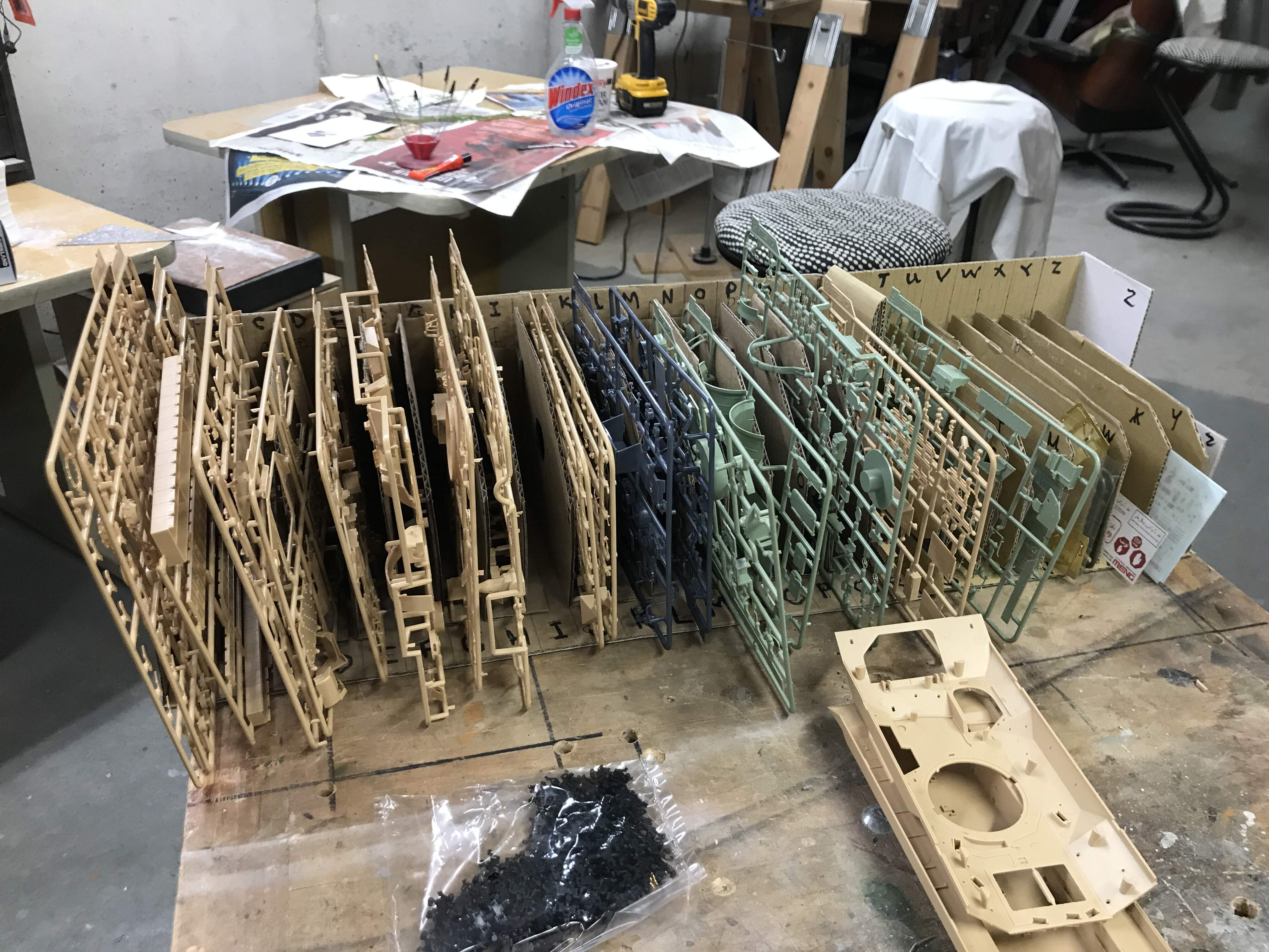
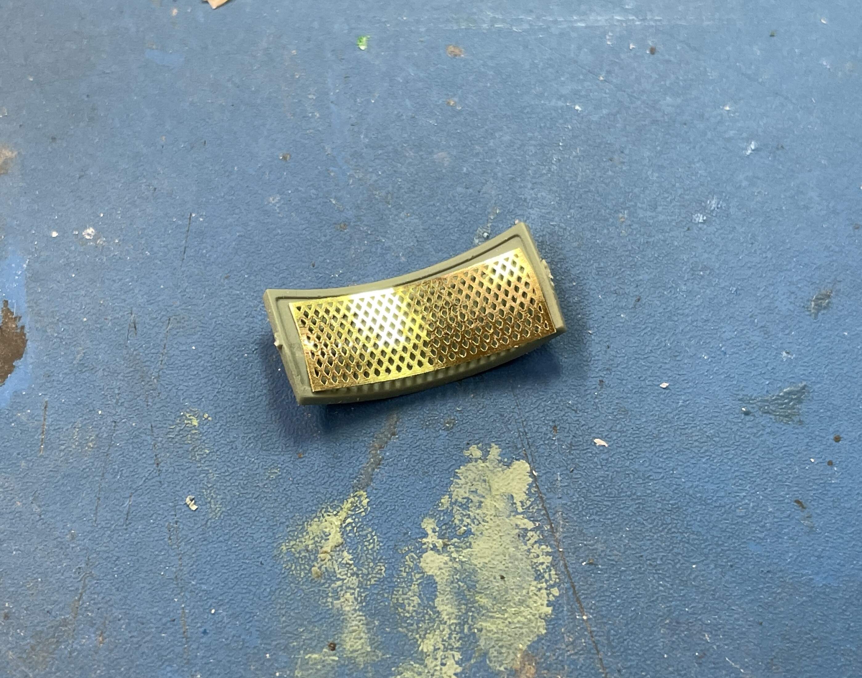
In this thread I’ll try and give some highlights and bring you up to date. I’m using one aftermarket set: Friulmodel Bradley Big-foot tracks. While I was excited with the Meng snap-together tracks as compared to the massively complex Ryefield Model Sherman tracks, I was disappointed that the tracks weren’t stable and came apart at the slightest side torque. I bought the Friulmodel tracks. They actually required less cleanup than the injection molded Meng track parts, and with a full pin going through the entire link, they are very strong. It did take some special handling to adjust the length after building them though. The Friulmodel kit came with a spool of 0.015" brass wire for the pin stock. It seemed a sloppy fit in the link tunnel, so I substituted it with 0.022" phos-bronze and drilled out the passages accordingly. Much better.

As a newbie, I’m limited to five pictures per post, so this post will be spread over several entries.

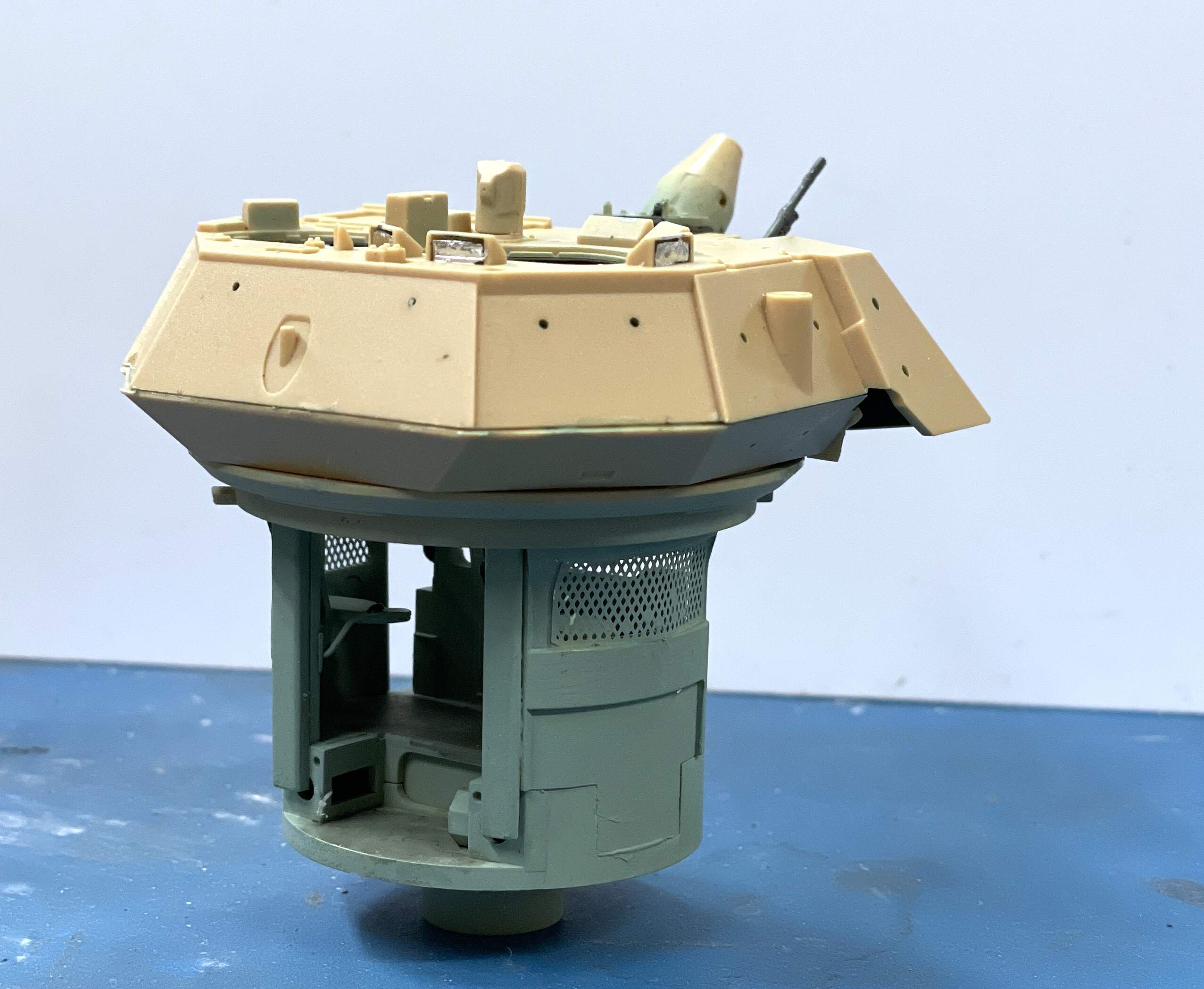
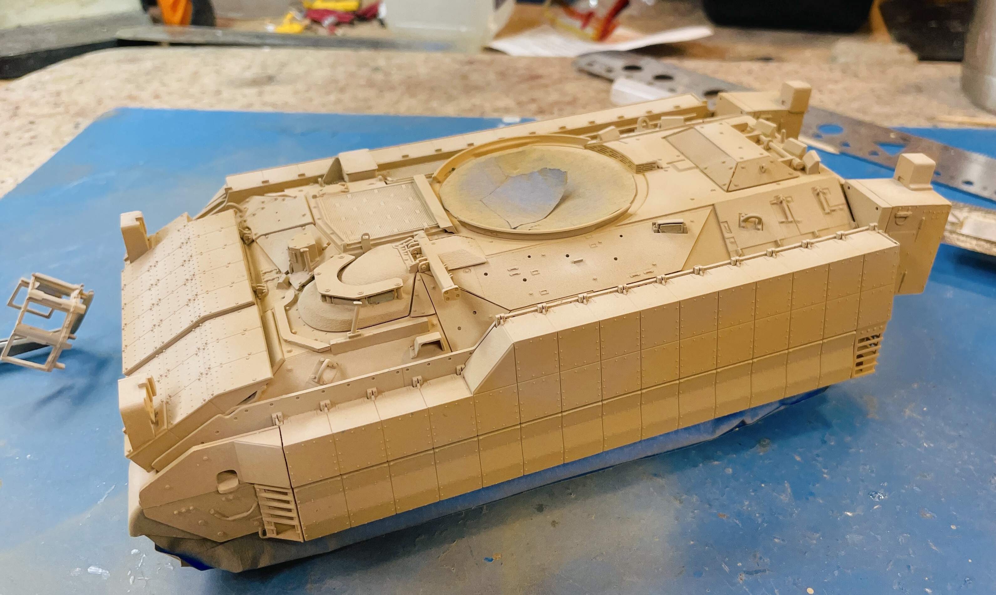
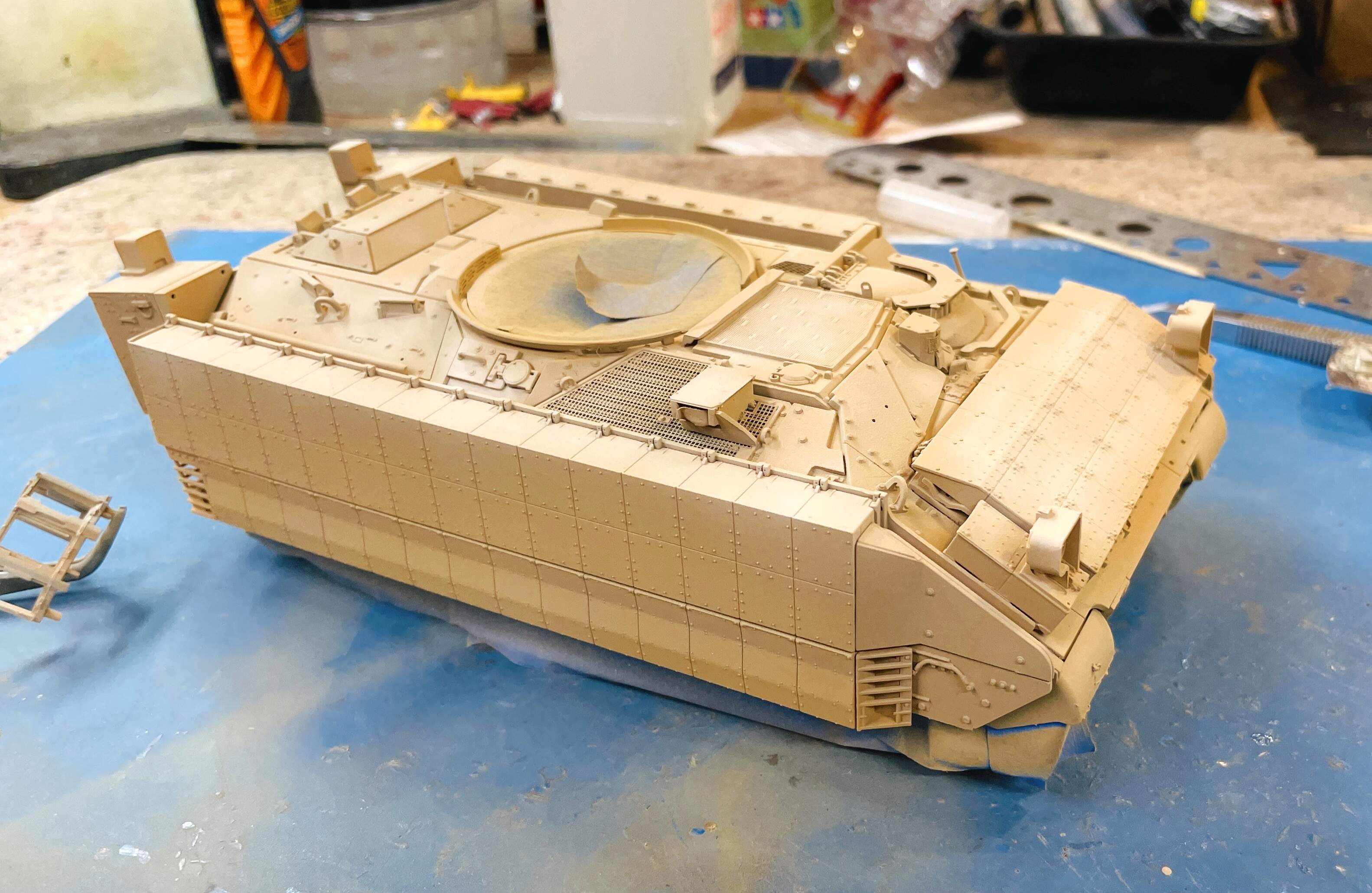
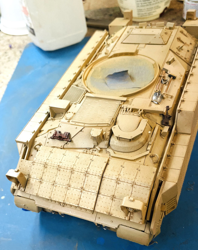
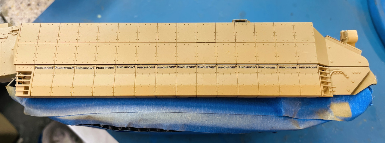
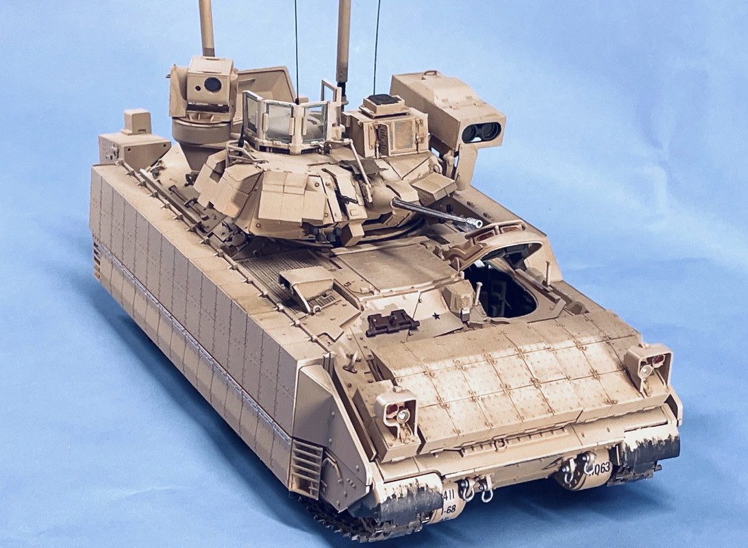
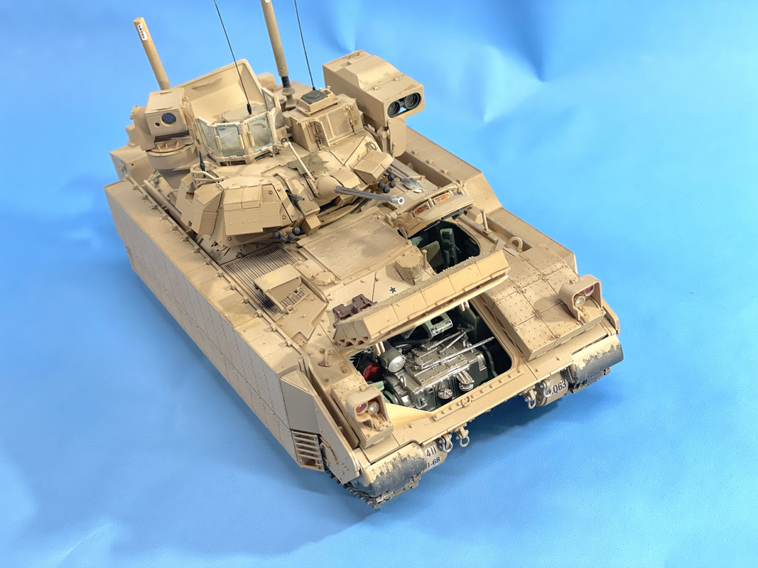
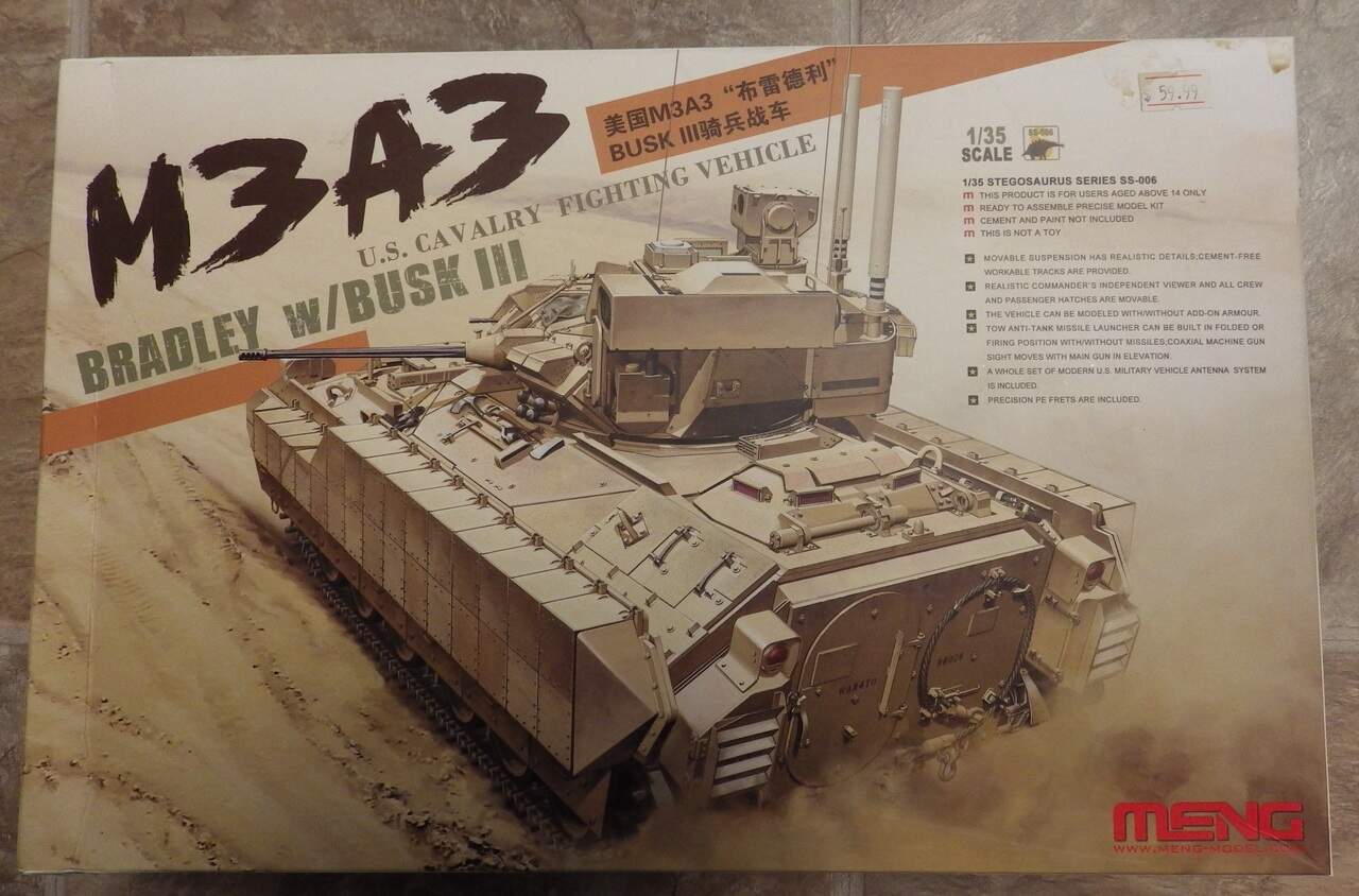
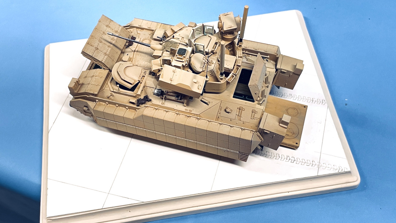
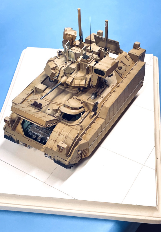
Meng, as you all know, is very similar to Tamiya in engineering and mold accuracy. It is a pleasant albeit complicated model to build. Total parts count is 874, but that includes about 170 links for the tracks. The road wheels, idler and drive sprockets are held with polycaps. Road wheels are articulated with styrene torsion bars that pass halfway across the floor pan. They work, but their suspension arms are quite flexible and really can’t do any real work. The suspension would really benefit from being die cast in metal, but that won’t happen.

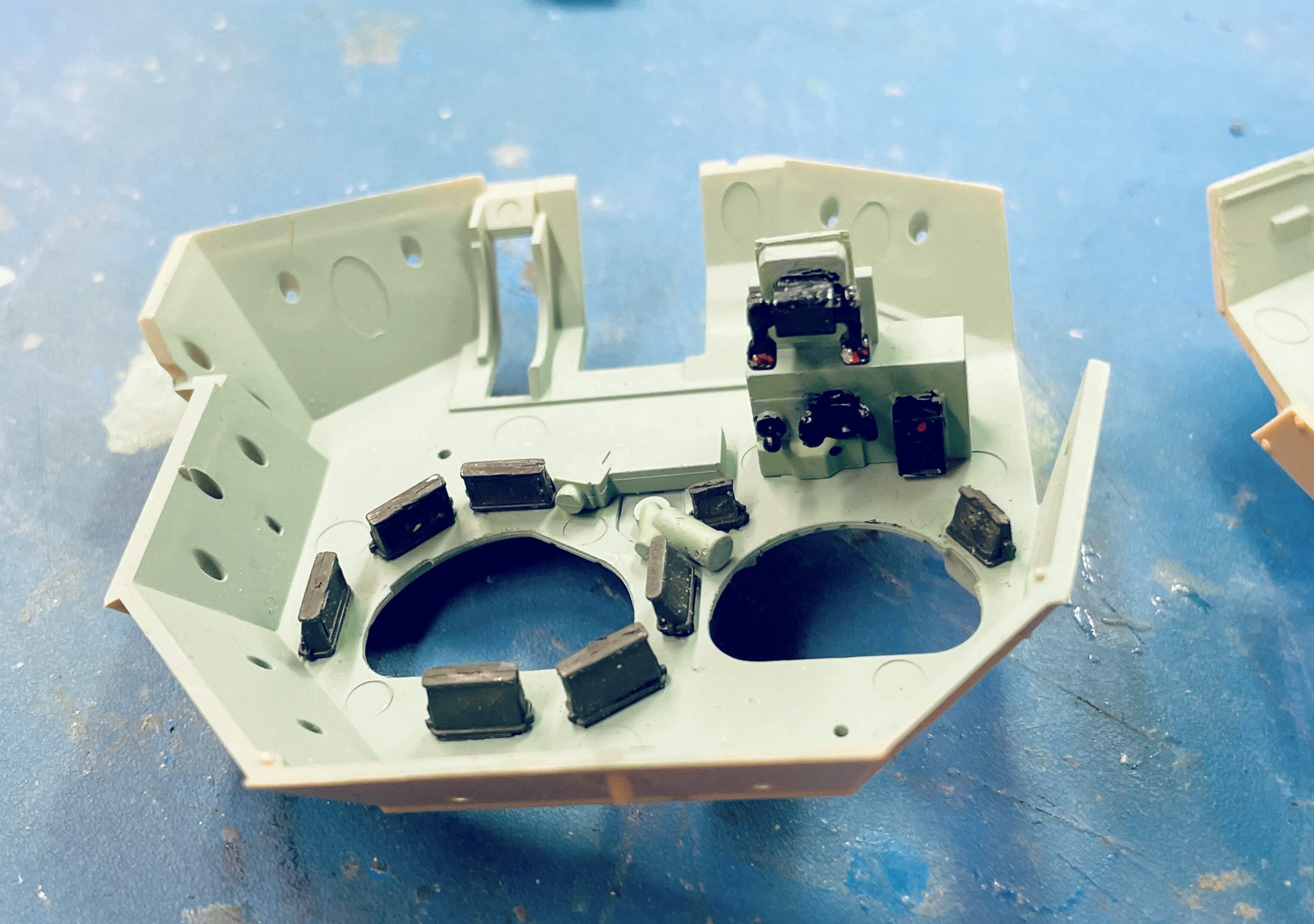
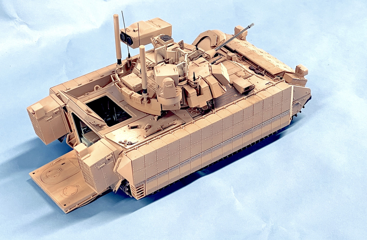
While the interior is fully detail, and I mean FULLY, you won’t see much of it when assembled. On my Ryefield Sherman I built a special display stand to hold the hull top above the bottom so you could see inside. I didn’t do it with this one. The Cummins 930VTA turbo diesel is a nice model in itself, but completely invisible in the model since it’s buried under the radiator and that’s covered by the hull top. All you see is the transmission and the trans-cooler heat exchanger at the engine’s front. You also don’t see any of the massive air cleaner box except for the forced air fan at it’s front. suspect the intercooler is in there for the turbo. I saying all this because I spent a lot of time doing perfect painting on engine and air cleaner never to be seen again. I even wasted time wrapping the exhaust manifolds to simulate the heat shields one the prototype, which also is not visible on the model.

The engine is upside down in this image. The picture points out the reinforcement of the radiator tube’s connection to the engine block. The glue connection was very insubstantial and I used some phos-bronze wire to strengthen it. I’m never afraid to add metal connections in a plastic kit when it adds to security.

Here’s the air cleaner showing the non-seen paint job.

The instructions called out “Blue” as the radiator color. I chose it make it appear as anodized aluminum with a base silver coat followed by Tamiya Clear Blue. I had trouble finding photos of the real power pack that showed the true color of some of this stuff. The gun metal gray for the engine proper appears to be correct in looking a Cummins information.

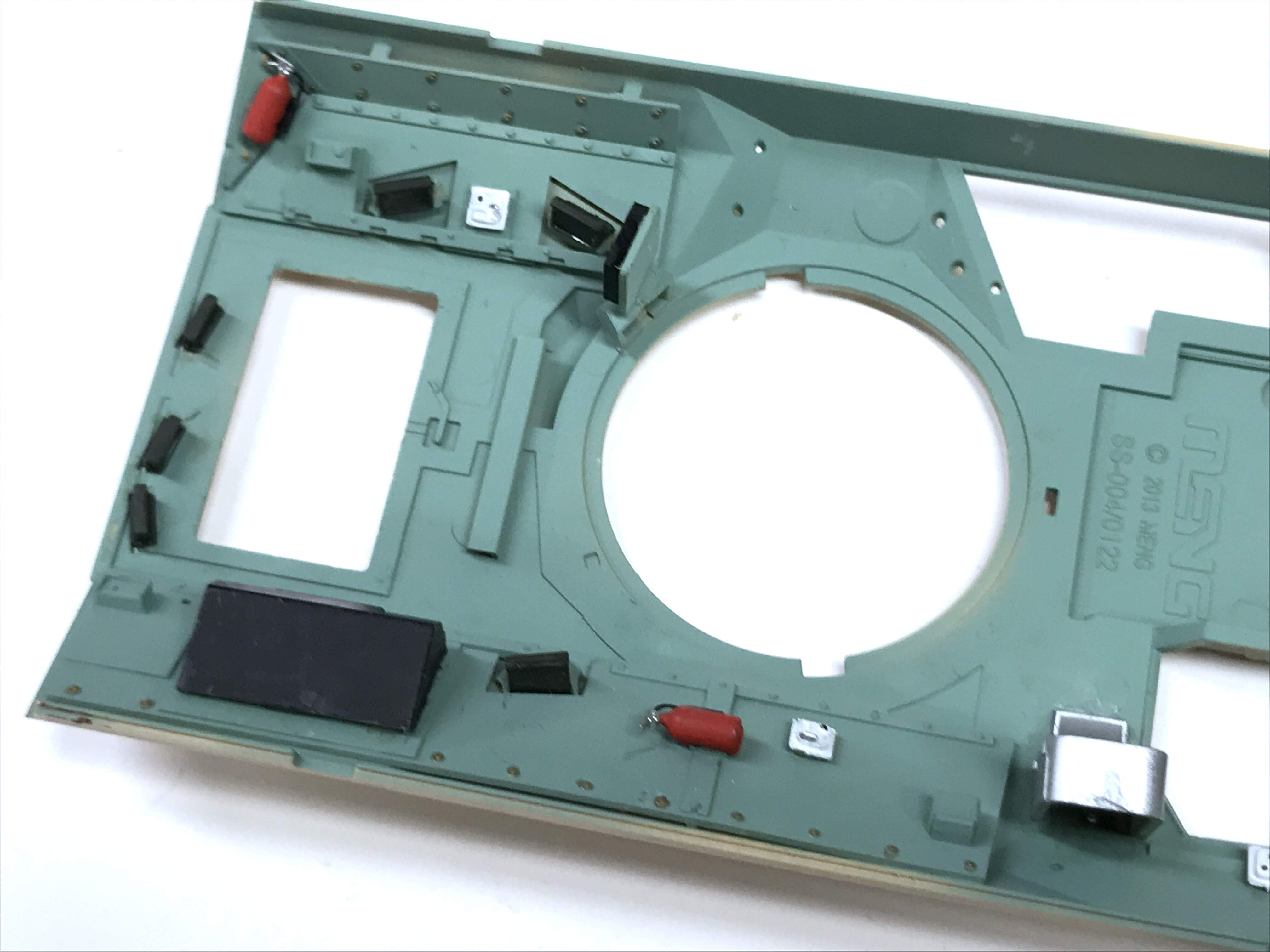
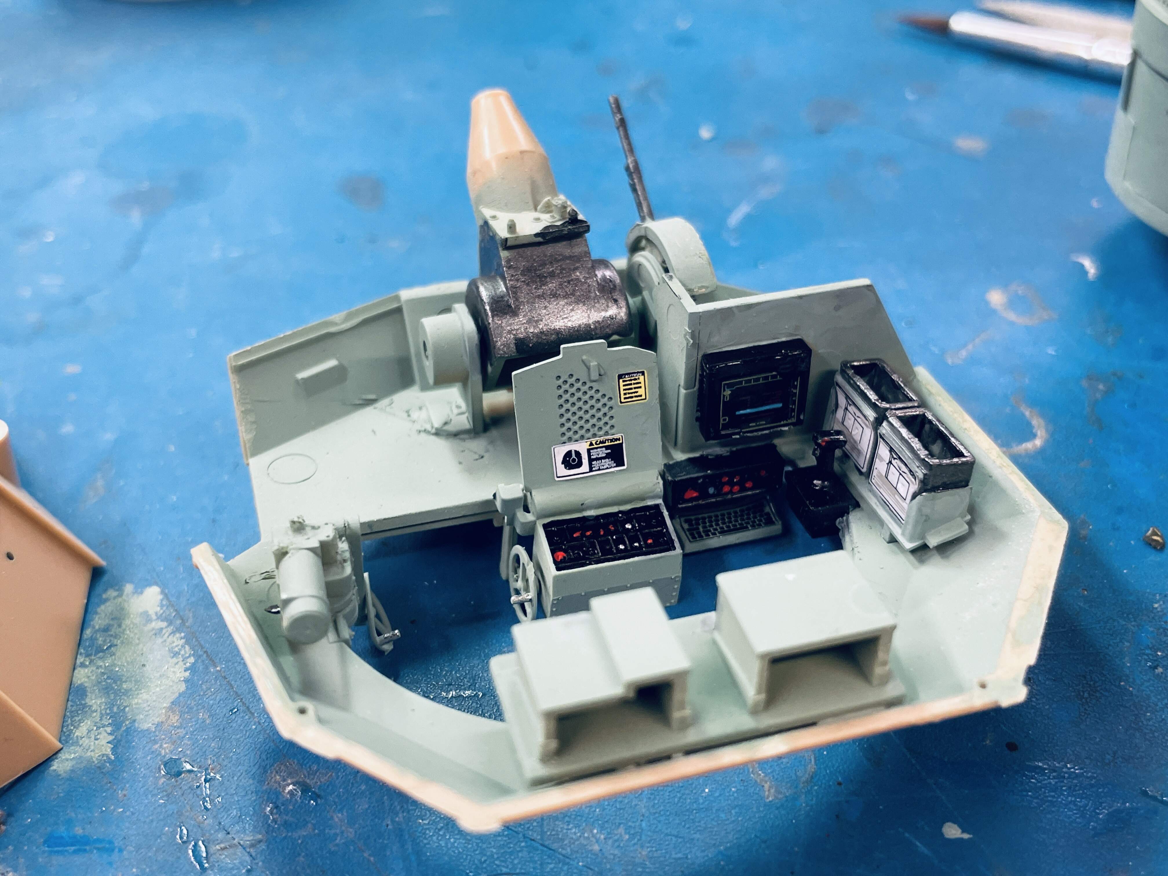
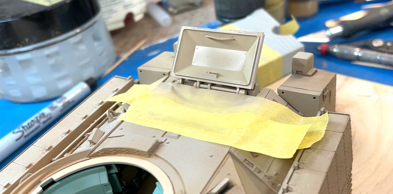
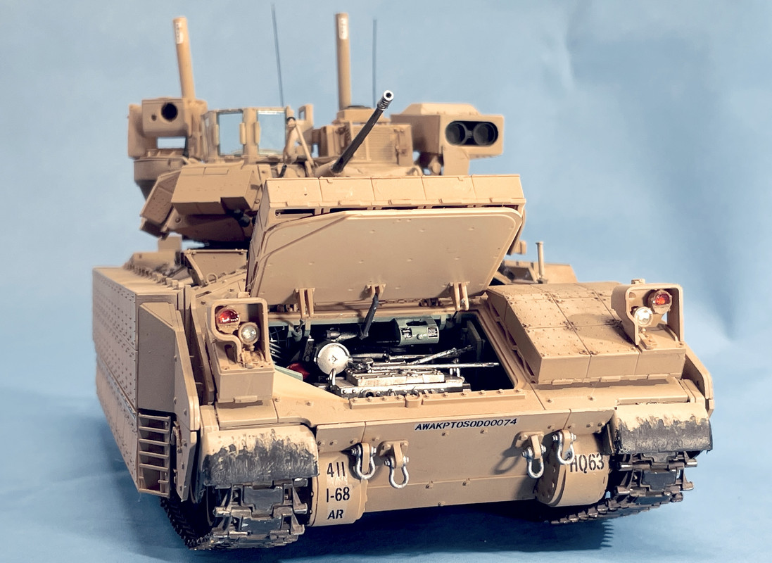
Good pictures of the driver’s compartment showed a missing seat-height adjustment lever so I made one out of 0.022" phos-bronze. I use Bondic UV-curing resin to create ball end on handles. I add the drop, hold the piece with the ball facing downward and rotate it so it forms a nice sphere and then hit it with the UV for about 5 seconds. I also use Bondic for clear lenses.

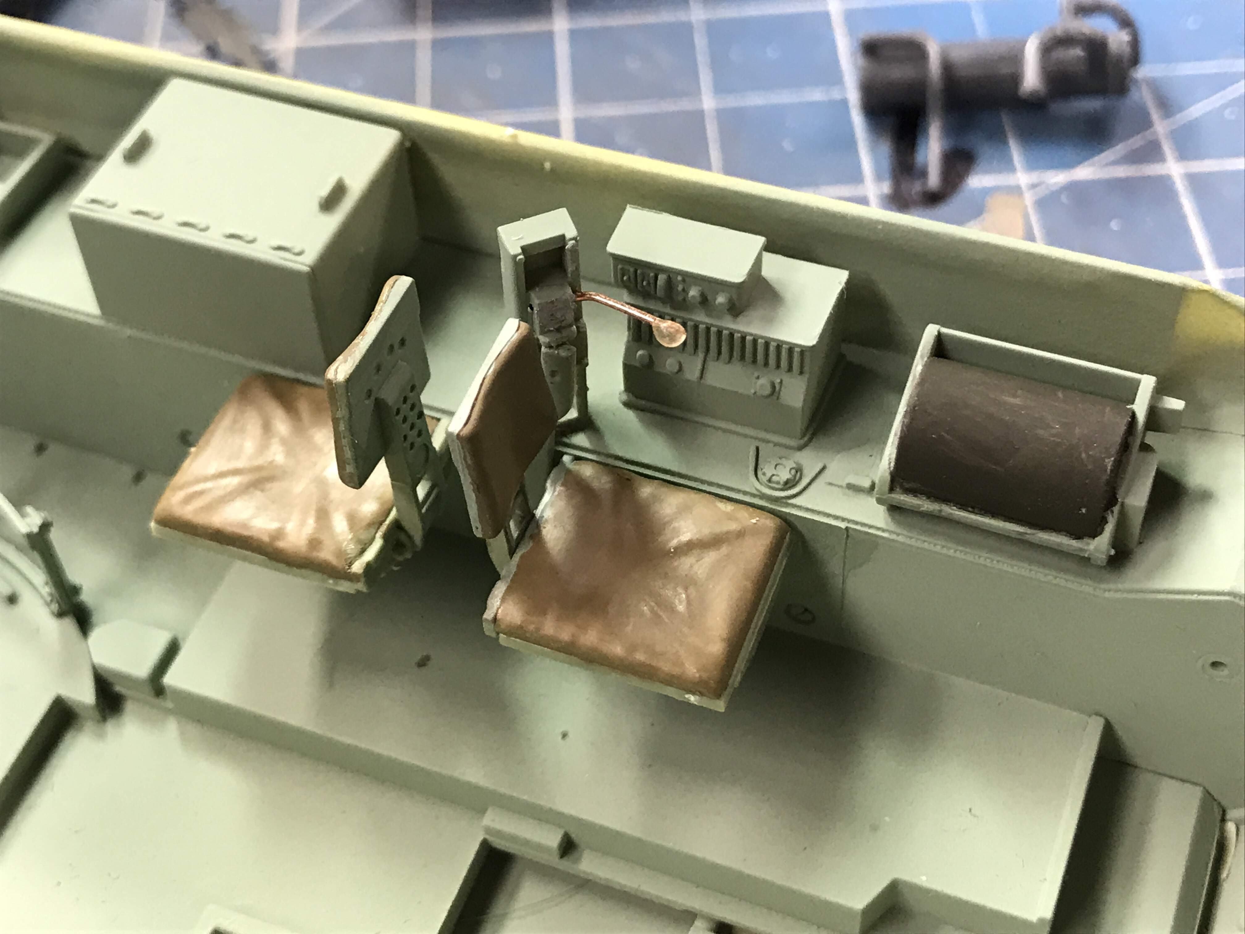
I mixed my own sea foam green using Tamiya Sky, a small quantity of blue and white. It came out pretty close. During college years and one year after, I spent my summers working at American Electronic Labs (AEL). it was the best summer job ever!

During my tenure, they had a contract to turn standard FMC M113 APCs into mobile ECM systems. This required stripping the tanks down to bare metal and rebuilding them completely adding an enormous amount of radio jamming equipment. I spent a lot of time in them and even got to drive them. This was during the early Viet Nam years, 1964 to 1968. Since they were new vehicles right off the assembly line… they even came with the 50 cal, M2 Browning strapped to the inside… they didn’t have preservative in them so needed driving once a month. AEL had a test track in the back lot and we drove them around on it. Like I said, “Really cool summer job!”

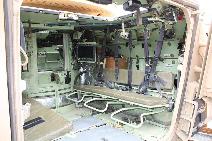
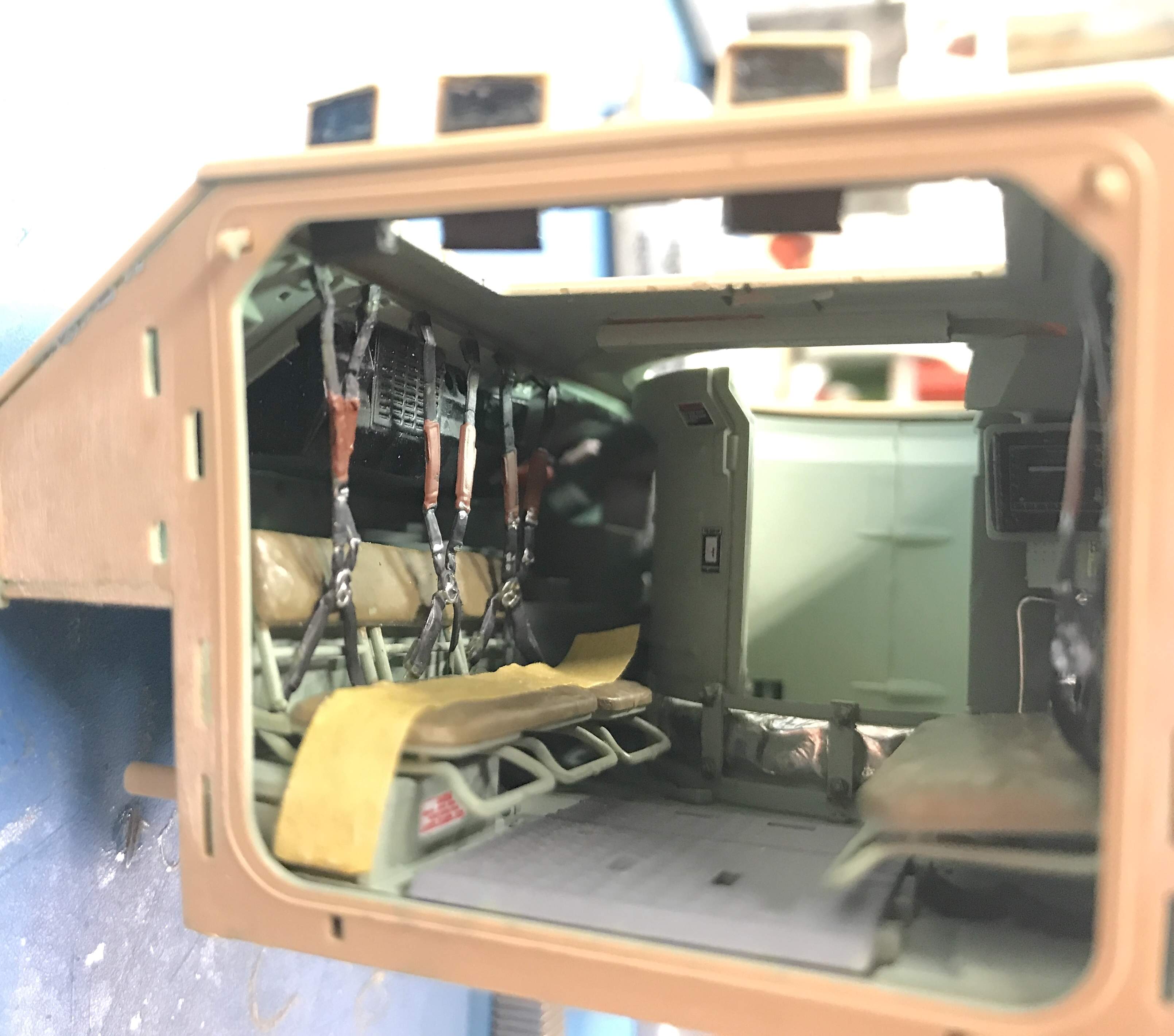
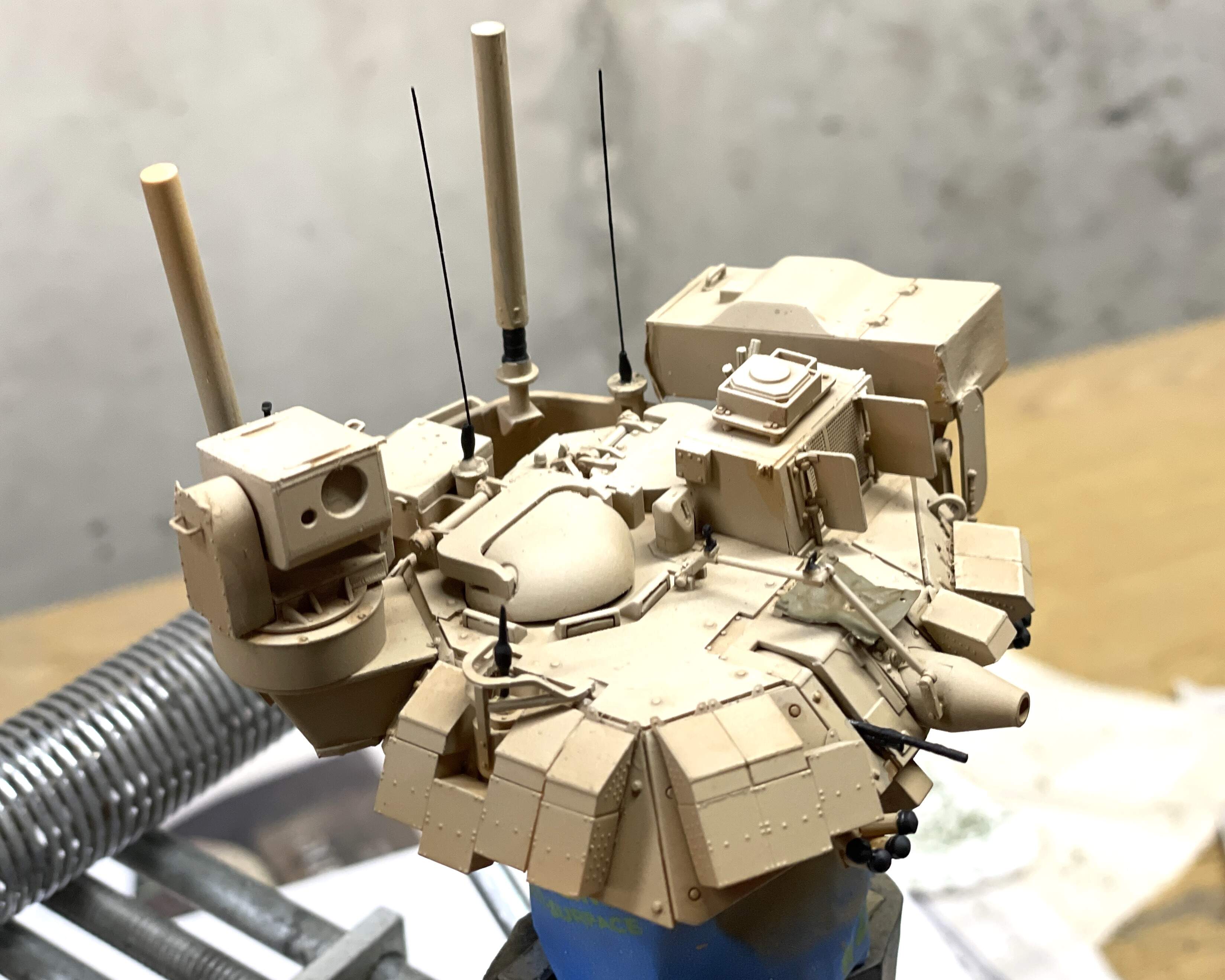
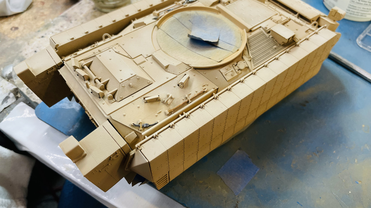
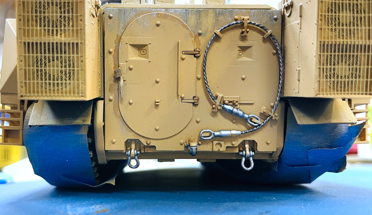
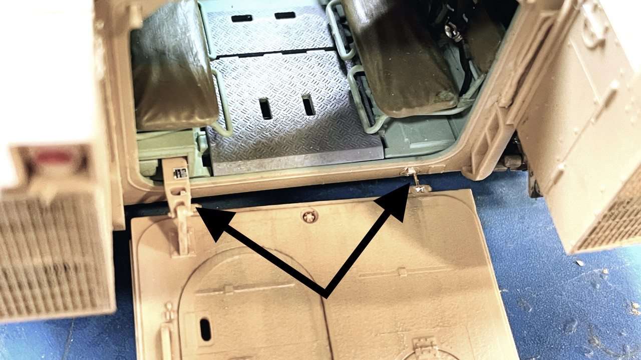
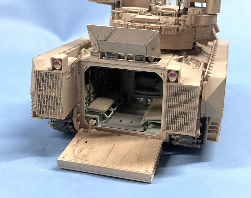
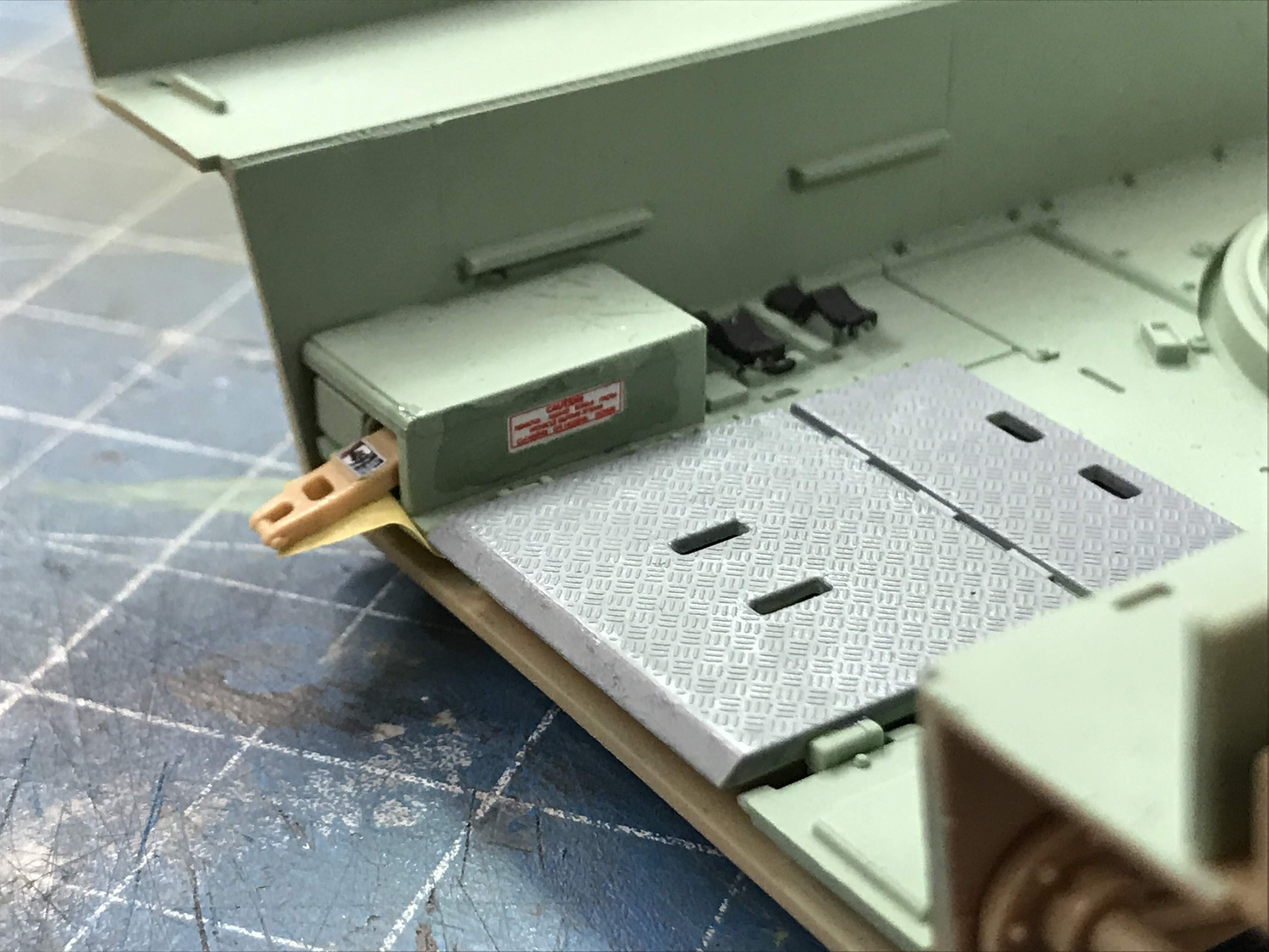
The tread plate on the floor is actually rubber on the rear Bradley so it doesn’t wear down to bare metal. It just gets a bit dirty. The lift link in the upper left is attached to the not-yet-installed lift gate. It kept falling out, so I taped it in place throughout the build until the door was installed.

That’s my five pics. On to another episode.

5 Likes

Wow this is looking fantastic! Your attention to detail is clearly very fine-tuned. I know your troubles with click-together tracks, I used them on my Border Model T-34 and it was almost impossible to keep them together.

Dennis

Part 2:

Crew seats were challenging to properly position since they’re only connected at the back. The foot rests do not touch the floor. The heat duct at the bottom of the turret basket, in the real thing, is wrapped with an aluminized insulation blanket. I simulated this by applying Bare Metal Foil to it before installation.

Here’s the real Bradley interior and the model’s for comparison.

The masking tape is still holding that pesky lift gate actuator lever. I added some nut/bolt/washer castings to simulate the ones on the bottom of the turret housing, but they’re a little oversized. Not a problem. If they were scale-sized, they may not be visible.

There’s a lot of stuff that goes onto the Bradley ceiling. Most of it will be very hard to visualize especially the areas over the driver’s compartment and the turret. In fact, almost nothing is visible inside the turret. AND because of the hugh quantity of details that go on the turret roof and how it interacts with the turret proper, you really can’t make the turret roof removable. The only way to show it would be to create a cutaway model and I wasn’t up to that.

I even forgot to install the overhead lighting in the driver’s compartment, but then realized no one would ever know unless I told them… whoops! I just did. My bad!

I believe that’s five images so I will stop and do another.

7 Likes

lovely neat, precise and very very detailed build … top work

One note on the last post… the seat belts were included and were flexible material that could be glued with styrene cement. I picked out their details with the Molotow Chrome pen. I find the Molotow is one of those supplies (Like Bondic) that you don’t know you need and then can’t live without. Kinda like my new Apple Watch.

For the last couple of big plastic kits I built I’ve been using a DIY sprue rack. I can’t believe I didn’t do this years ago. I cobbled it together with some scrap cardboard and a hot glue gun. When I built the first one, I made the slots too narrow. On my second version I ended at the letter “R”. I quickly found that the big models use most of the alphabet so this one goes to “Z”.

The rack probably saves an hour or more of wasted time fumbling around for a particular sprue.

When I loaded the rack, I noticed that “O” and “Q” were missing. I incorrectly assumed that this was intentional and didn’t think about it again. That was until it was time to add the appliqué armor to the hull top. "Where the heck is sprue “Q?” Nowhere! That’s where!

I sent an eMail to Meng Customer Support in China and got a quick response that they would send me one. I worked around the missing parts as best as I could. After a month passed I wrote to ask where were the parts and they apologized for forgetting to post it. They quickly corrected the error and new parts came in less than a week. I forgave them.

I was disappointed that the Meng turret interior DID NOT include the gun breach and mechanism, unlike the Ryefield Sherman where, not only did the include the entire gun assembly, but even had a spring so the whole deal recoiled realistically. But upon reflection, there would be no way to view it. Unlike the Sherman, where you can see the gun assembly from below when you lift off the turret, the Bradley’s gun mechanism is not viewable.

Regardless, there’s a ton of detail inside including the commander’s joy stick controller and the LCD status screen. There’s even a keyboard decal to go onto the keyboard below the screen. Good luck viewing all this, but it’s there.

I just read that an upgrade has been approved to add a joystick and system for the gunner’s position to augment the commander’s.

Both the IR scope and the TOW missile launcher are retained by polycaps so they both articulate. I used Microscale Liquid Mask to prevent paint from fouling the transparent windows on the IR, but found the MS mask is not compatible with water-based paints. The paints dissolve the mask and make it almost impossible to remove without damaging the surface. I’ve recently purchased the Molotow Mask Pen that IS compatible with water-based paint. The MS product has labeling to the effect that it’s not for water-based paint, but I didn’t know there was any alternative.

I really wanted to make the periscopes as realistic as possible, but the results were sub-par due to two factors: the first coat, Molotow Chrome, is alcohol-based and is degraded by Tamiya alcohol-based clear colors, and second, the aforementioned MS Liquid Mask problem. They’re orange, but no where near as reflective as I wanted them to be. For the final hull painting I’m remarked them with the molotow.

In the above, you can seen the orange, anti-laser coating on the periscopes. You can also see my callout on the two small add-on Explosive Reactive Armor (ERA) panels. I don’t know about you, but gluing PE to styrene with CA is an often exasperating activity for me. If it goes on the first time…. GOOD! But, if it falls off or doesn’t stick right and you have to re-glue, it gets worse and worse. And holding PE to PE with CA isn’t much better. On the ship models I’ve built, where I’ve scratch-built elaborate antenna structures out of brass, I’ve resorted to soldering the brass, not gluing it. If there’s interest, I’ll post a thread on exactly how I do this.

On the turret basket there are two PE open-mesh screens on the bottom. These follow a compound curve and Meng was nice enough to include a forming tool to shape them. The first one I did, I formed the part on the wrong side of the former trying to stretch it over the backside and it didn’t come out as it should, then I realized that you form the PE on the inside and it shaped much better.

I’ve just received an eMail that I’ve been upgraded to Basic User. I am assuming that this means I can load more than five images. Let’s test that out…

The TOW missile launcher has a very small and fragile link that retains the door when the launcher swivels up to the firing position. I reinforced this joint with some 0.095" guitar High-E string. As a guitar player, and one who occasionally changes strings (not often enough) I find the old one useful for model making. For instance, the guy wires on the Essex antenna are those as well as the whip antenna on the Bradley. WARNING: Don’t cut music wire with your good sprue cutters. Get a tool that’s designed to cut hardened wire. Otherwise, you will have a permanent divot in the cutter’s blade since the wire is as hard as the tool!!

I used JB-Weld metal-filled epoxy to glue guys wires like these in place. I also use J-B Weld in places that other people might use CA. BTW: I use GEL CA whenever possible for all my CA glue jobs. You can us very tiny amounts that stay put and don’t run all over the place. It cures slower so you can adjust a bit. This is very useful when gluing fine ship details in place.

The kit called for 80 track links per side. I built the Friulmodel tracks to that spec. I used a 0.022" carbide drill to reopen any holes that were closed with flash and cut the phos-bronze pins so they would go to the bottom (the holes do not pass all the way through) and so the pin’s top is at the bottom of the small cup at the outer opening. When I got the correct size, I stuck the piece to a piece of double sided tape and cut the remaining 160 to that length. I didn’t cut them all at one, but did everything in batches of 10 just to break the monotony.

After assembling I degreased the tracks in my ultrasonic cleaner to prepare for paint. Painting was as follows:

  1. Tamiya Dark Iron airbrushed
  2. Vallejo Dark Flesh (a great rust base color) airbrushed. Didn’t realize that it was Vallejo until I smelled it. I keep pre-mixed paints in separate bottles for airbrushing. Vallejo doesn’t like IPA thinners and will sometimes clump and clog airbrushes. Best to use acrylic thinner. But I didn’t know this. As it was it worked okay.
  3. Light coating of Tamiya Buff.
  4. Hand painting track pads with Tamiya Rubber Black cut with a little white
  5. Dusting with light earth colored pastels powder
  6. Scrape off paint on track guide lugs and the flat bars protruding from the link hinge area. Saw this wear on some closeup images of Bradley track.

The track won’t go on the tank if the middle idler where is glued on, so if you haven’t already done so, don’t glue it on until after the track is on. I didn’t! I broke the idlers off and pinned them with 0.032" phos-bronze wire. After installation the track was floppy. It ultimately needed two links removed. That was a concern. The track pins are retained by thick CA and a tiny NBW casting. I removed the casting, but you can’t really get the pin because it’s flush at the bottom of the hole. Instead I selectively destroyed the link around the pin on the to-be-removed link so I exposed the pin and could start pushing it out. I could grab it with pliers. The track went back together without difficulty. Friulmodel includes a lot of extra links and end bolts.

I’m getting tired, so I stop for this session. Let’s see if all the pictures post.

8 Likes

Looking great!

Seriously great work and detailing… Also very helpful for others with this to do :+1:

Thanks fellas!

Yesterday I painted the hull three coats with my Badger 150 airbrush. Coat 1 was straight Tamiya Desert Yellow, Coat 2 was lightened Desert Yellow and the final coat was even lighter. I used the full color on surfaces would not see the sun and lightened up from there.

Doing punch list items: Track tools, rear lights, spare track link, repaint sides, clear coat, etc.

I don’t know about you, but airbrushing a multi-coat, multi-shade finish is almost impossible to touch up easily. I painted the track tools while on the sprue, the glued them to the hull. The paint got a bit munged up on one of the panels so I attempted to brush paint it to bring it back. Trouble was I couldn’t get the shading right. First it was too dark, then too yellow and finally, probably a bit too light. It’s due to the eveness that an airbrush feathers one shade to another. It’s almost impossible to duplicate this with a brush… for me. So you might see some shading differences. I gave up on the brush painting and resorted to the air brush at least get the feathering right.

The tools on the other side came out a little better.

After putting these in place I airbrushed the whole deal with Tamiya Clear Gloss. I pre-mix my colors in the Badger compatible bottles and had some Tamiya Clear Gloss already containing some, although it needed more. After adding the clear, IPA and a few drops of extender to aid in flow, I noticed that it was cloudy. Okay! The bottle didn’t have clear gloss. It was clear flat, so I dumped it and made some more. The clear gloss is to facilitate using Tamiya panel accent which, when put on a flat finish, flows all over the place and not just in the targeted grooves. It was still tacky by the end of the session and it was booming like crazy outside with a really classic thunderstorm, so I stopped work early.

I had installed the rear light and painted the turn signal and fog light lenses with Tamiya clear red, which also need to dry fully overnight.

I also screwed up the paint next to the exhaust stack. I wanted to add some soot powder. The powder stuck to the not-quite-dried clear and made it very black. I attempted to remove it and using a brush with a little IPA, ended up removing the top coat back to the really yellow stuff. I attempted to get that back to the right shade, but it will still need more work I’m afraid. I’ll use the airbrush tomorrow. (is “air brush” one word or two… I seem to use both)

All of this trouble goes back to my long-standing understanding of my skills. I am not patient… I am persistent. When I screw up, it’s always becasue I didn’t give paint or glue enough time to dry properly.

Next session I’ll continue to do some final finishing and add the remaining decals. Then I’ll dull coat the whole deal and it will be finished. And on to the base.

4 Likes

Need to stop staring at your Apple Watch!:watch::laughing:
Kidding aside… Your work is freakin’ amazing!
Makes me realize… Sheesh! I am really slow!… Need to start staring at my Apple Watch!:watch::sweat_smile:

—mike

Thank you Mike. Sometimes, I’m too close to it. Posting all this crap gives me the opportunity to go back are re-read my own builds. Sometimes it amazes me that I’m able to do this stuff. While you’re in the heat of battle, you don’t stop and admire it. I would recommend everyone to post build threads, not just finished models. I have learned a huge amount from the people that read them and comment. I can give several awesome examples.

Example 1: In 2011, when I wanted to rebuild the Tamiya Missouri (the first time was in 1985) and wanted to pull out all the stops including replacing the plastic prop shafts with metal, but didn’t know what color they would be. I went on Google and asked, “What color are the Iowa Class prop shafts”, and got several responses. One led me to Worldaffairsboard.com website. It was an eclectic list of forums and threads on every topic under the sun, mostly military. The site was populated by a lot of active and retired military people. I found the “Battleship Board” where all the posts were about them. I joined the forum and asked the question. I got back a response from a guy whose forum name was “Rusty Battleship”. He posted this picture.

Missouri Prop Shaft

That’s him standing on the Missouri’s prop shaft when it was being refitted in the mid-80s. The shafts are white due to the anti-fouling paint on them. Rusty’s real name was Dick Langraff. He was the superintendent of the Long Beach Navy Yard and supervised the refitting of all the Iowas. He knew every rivet, tank, bulkhead, valve on the entire ship. He suggested that I post the build in their “Modelers Corner”. I did. Not only was Dick constantly guiding my build, but there was also a docent from the USS New Jersey Museum Ship that contributed too. Through their contacts, I was connected to the curator of the USS Missouri Museum at Pearl Harbor and offered a place to display my model in the Captain’s Cabin. The only caveat, I had to get it there. That wouldn’t work so the model stays with me.

Example 2: I was posting the build of my 1:32 Trumpeter TBM Avenger and one of the readers was the owner of a REAL one which he was in process of restoring. He kept supplying me of detailed pictures of all kinds of things that I would have never found otherwise. I opened access panels on the model and was helped with his pictures to see what was behind them.

I could go one, but I have a lot to report on the Bradley

Today was the end game for the Bradley itself. I still have to create the display base. A lot of odds and ends and a couple of heart stoppers, and some not-so-acute concerns.

First up; detail painting the back of the lift gate. Unfortunately, all this beauty will be hard to view since I’m posing it with the gate dropped, but we all know it’s there. Notice, I repositioned the door handle so it’s in the correct downward position. I also made some bare metal where it would be rubbing on the ground. Painted the cable and liked how it worked out. Painted the towing clevises with my “galvanized steel” color which is a flat aluminum and gun metal mix.

I went over the entire vehicle with Tamiya Brown Panel Accent. I put in in the upper ERA seams, and the granular surface (anti-slip?) on the upper and front blocks, various seams, bolts and hinges, and any other thing that I thought needed accenting. After it dried a bit I removed the excess with Q-tips dampened with low-odor mineral spirits. The effect is subtle, not bold.

I added the “PINCHPOINT” decals the reside at the upper and lower side ERA joint. There are 15 on each side. Meng inlcuded 2 extra. You will need them.

The decals silvered a bit even with the Tamiya clear gloss coating.

I opened the drop gate to prepare the exposed upper surface. I glued the hinges into the open position, but they were not holding and were, in fact, breaking. After doing the surface treatment off the vehicle, I drilled and pinned the hinges with 0.022" phos-bronze. Much more secure. I took the pictue before pushing them all the way home. I used med CA on the pins as I inserted them. The drop gate is no longer positionable, but considering how frail the kit hinges were, it really never was.

The lift gate was treated with various pastel powders, brown panel accent and very light coat of AK Interactive Real Metal.

Through all the handling, the vertical thingamabob left of the driver’s hatch (Gino, what is that?) kept bending over and was in the process of breaking. I removed it and attempted to drill it with the small 0.011" drill for the guitar string, but the hole was not centering and broke out of the side. I substituted some styrene rod and it worked. I then cut off the tiny flat piece from the original and glued it to the new one.

And then the outer shell of one of the drive sprockets fell off. This was potentially more troublesome since access was severaly limited with the ERA skirts and mud flaps now blocking most of the area. And the sprocket face has a key slot that needs to align with the other half. I use Testor’s tube cement, and worked it under all the obstacles and amazingly got it to settle in correctly.

I had trouble installing the light glazing. Instead of breaking anything I chose to use Bondic on the headlights. I was able to put in the turnsignal/breaklights, but they didn’t snuggle into the housing as they should. I used Testor’s Canopy Cement.

The model was ready for the final coat of Tamiya Clear Flat which I applied.

I had a lot of trouble removing the Molotow Liquid Mask. The stuff just wouldn’t pull off in a sheet. It came off in little bits and required lots of fussing, not much better than the Microscale. Next time I do periscopes I’m using masking tape or bare metal foil. I put a coat of Pledge with Future on all the periscopes to give a bit more luster after all the scraping.

I saw that the top hatch also had a rubber seal raised area and thought it should be black. I attempted… poorly… to color it with a black Sharpie and made a big mess. It required a repaint. Actually, I had never painted the underside thinking the kit’s yellow might work for an underexposed area. I masked the opening and used the Badger Fine Line airbrush. No harm no foul!

With that last task… oh… and I put some gloss Tamiya Clear Smoke around the fuel filler caps. Not a lot of spillage, just a little bit… It was time to make the turret to the hull. Got it together without breaking anything. Miracle!

I painted the aft end of the Bushmaster barrel with Gun Metal, used some Testor’s Tube Cement and install the gun. I then finish painting it on the tank. I highlight the muzzle wit the metal paste since pictures show that firings polish that area a bit.

And the model IS DONE! Here are some beauty shots. I found that right out of the phone’s camera, the finish was too yellow… much more than appeared to my eyes. I messed with the post-processing controls: Exposure, Temperature, Contrast, Highlights and Shadows and got it a little better. But when I reduced the Saturation, it finally looked like it did in the flesh.

I still have to build the base and will do that next week. Since the machine is going to be sitting with all its opening open, I’m going to situate in an area that looks like motor pool. That means a concrete pad, and not a desert road. I’ll be posting that too. I got the hood open, put the metal lift piston rods in place and reinstalled the hold-open latch and then took these pictures.

This was a complex and rewarding model. Not quite as complex as the Ryefield Model Sherman, but darn close. The Friulmodel tracks really helped. The kit tracks would have been very frustrating to me unless I glued them together. It would have been less frustrating if the “Q” parts were included, but I was able to work around that without losing much time and all’s well that ends well. It was my first Meng kit and it was well engineered. The working hinges on the hood and drop gate, while scale-sized are way undersized if they’re actually supposed to work. On both parts one hinge (female side) fractured in just trying to assemble them in the first place, not when I was trying to operate them. While I was disappointed in not having the full gun breach detail, you would not see any of it at all. I’m looking for some crew members for this beast. I have marty at Scale Reproductions, Inc., finding me some.

I learned a lot about Bradleys in researching this build. They’re an impressive machine that keeps getting upgraded. This model is not for the faint of heart, but it’s a rewarding build.

10 Likes

It looks like it came out nicely. Good job.

It is an anti-foul bar for the wires coming from the TOW missile when fired. TOW is wire-guided and trails them behind it. The wires would occasionally get tangled on the drivers’ hatch and break, causing the missile to fail and go into the ground. The anti-foul bars (both sides of the hatch) keep the wires from tangling and breaking. An easy solution.

I thought that was a wire cutter, to protect the driver when operating open hatch, similar to what was used on jeeps in WWII.
Ken

Nope, anti-foul bars for the TOW guidance wires.

@Builder2010 that’s a very impressive Bradley :clap:

Likewise, the TBM Avenger looks amazing too. :clap:

Great work @Builder2010. It’s a nice kit and I was hoping Meng would do other version of this vehicle but that did happen.

They did do the M3A3 CFV. A slightly different version.

Has this uparmored version ever seen service outside Iraq?

Not really, the ERA blocks are only used in combat. They were used in Iraq.

A PLT (4) was recently deployed to Northern Syria. Note they have T161 tracks, like the Kinetic M3A3 kit. I can’t tell if it is an M2A3 or M3A3 though.

No Bradleys were deployed to Afghanistan. They have also been used for training (inert ones) in Europe just to show troops how to install them, but not used out in the field.

1 Like

So I’m guessing the extra weight is the reason for the kit not being permanently installed? I also have the Meng kit but was hoping i could paint it in NATO colors.

The extra weight has necessitated strengthening the torsion bars and going from 500hp to 600hp. They can’t make it much heavier.

Work on the base has begun in earnest. I painted the edges with an off-white craft paint. The display surface gets glued on the flat part of the base so I didn’t need to paint any of that.

I’m going to attempt to use Bristol Board as the base material. If it doesn’t work, I will use something else. I’m going to make it as a concrete pad with expansion strips every 10 scale ft (3.42" at 1:35). I used the paint template that came with the Meng model to paint the tread pads to trace tread marks on the base… this is not the final version, but was done for layout purposes. I thought to have the tracks curving into the parking slot, with the outer track scribing a curve and the inner track skid steering in place. But the results are not going to work. The tank wouldn’t make that turn.

Instead, I’m making the track marks going straight in.

Here’s another view.

I will have rough dirt/sand on the other side of the straight line in front of the vehicle. I may put a short piece of chain link fencing at that spot to frame it in.

No one noticed, including me, that the right door of the gunner’s optical system had fallen off. I took all the Friday pictures with that door missing. I noticed it today and the had to find it. I thought I knocked it off today since I was “sure” that it was there before. Then I checked all the previous images it was missing! I ended up sweeping the floor around my work station and DID find it and reinstalled with a small quantity of Gel CA and accelerator. Dodged a bullet since I was afraid that I might have tossed it out with the rest of the mess in my Friday clean up.