Not crazy at all, looks like plenty of components to make a good wreck of many an AFV or even a crash-landed aircraft despite the slight scale difference 1:35 to (typically) 1:32. Loving your work on this dozer, I’m sold 

1 Like
3 Likes
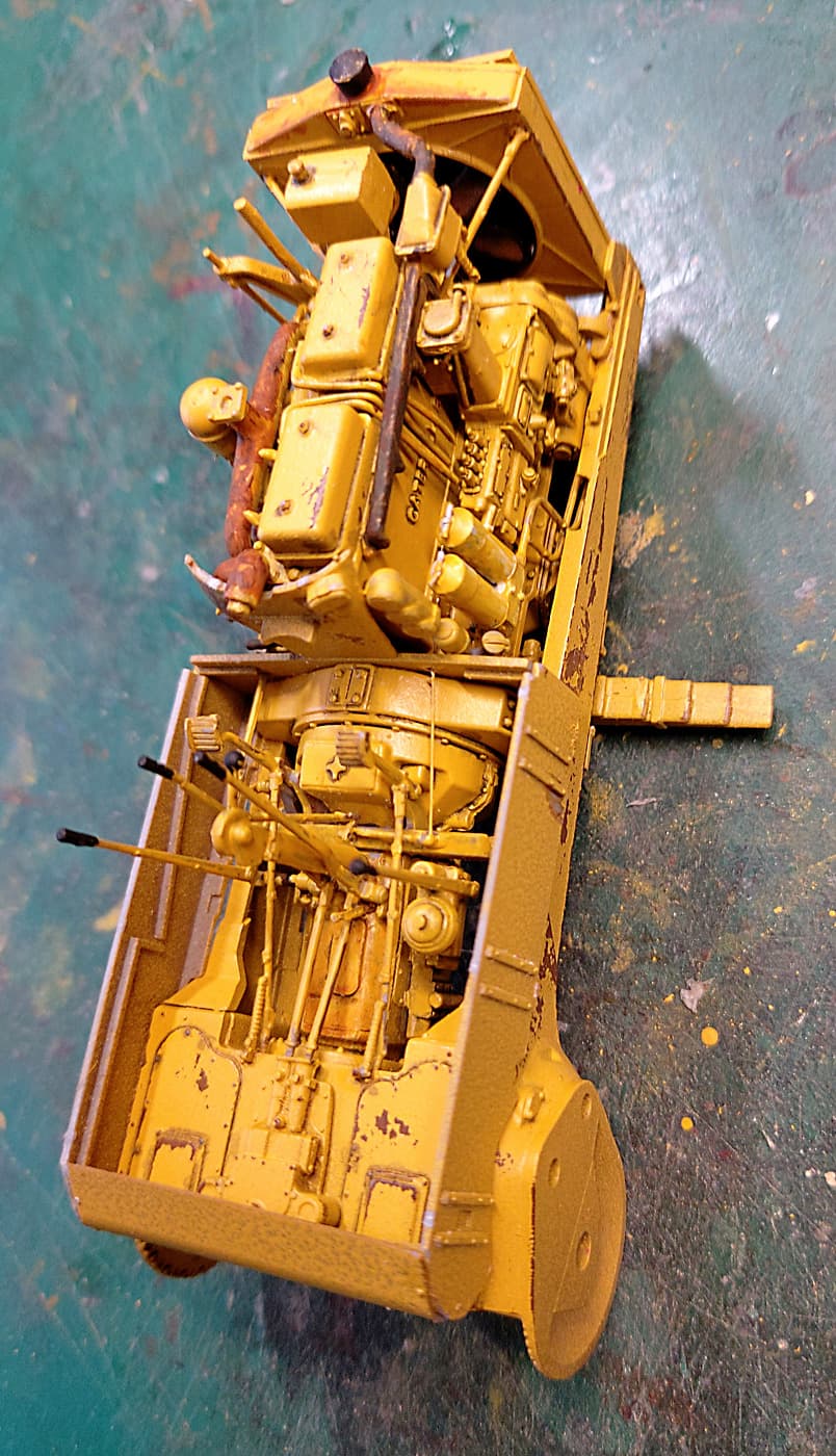
Last one for today. Boss has some chores she’s tapping her foot about! 
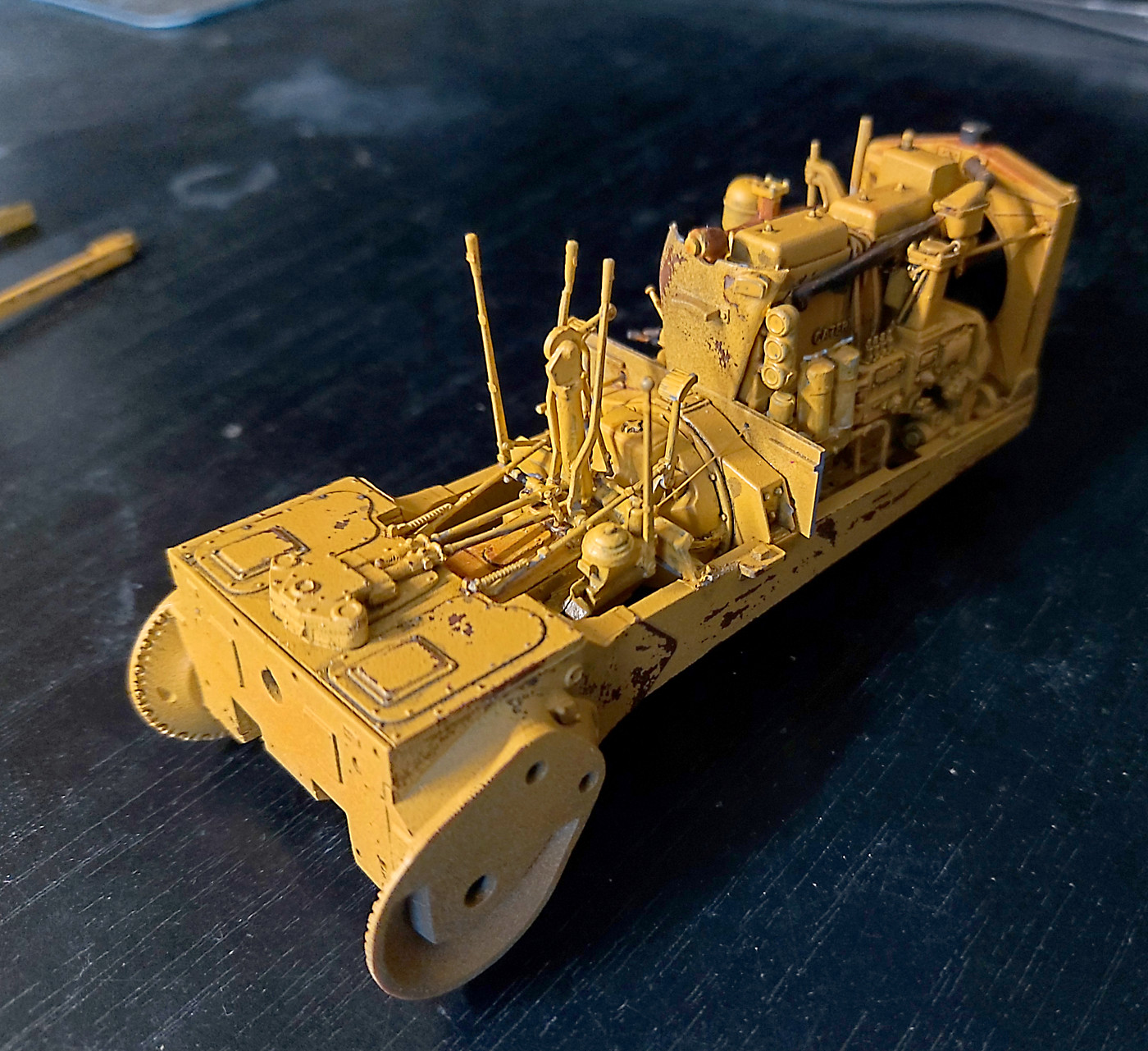
Most the time spent on installing the control levers. This is a step that needs a clear mind. Lots of will power. So many sprue gates. In the images you can still see them. But cleaning them up any more will end in broken parts and lots of tears. Anyone contemplating this kit read and reread the instructions.
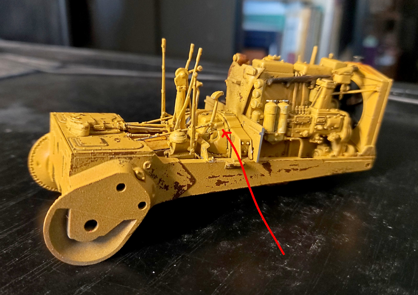
The red arrow points to a PE. A very fine and very small PE. Human hair type of size. It’s a control linkage.
bruce
4 Likes
4 Likes
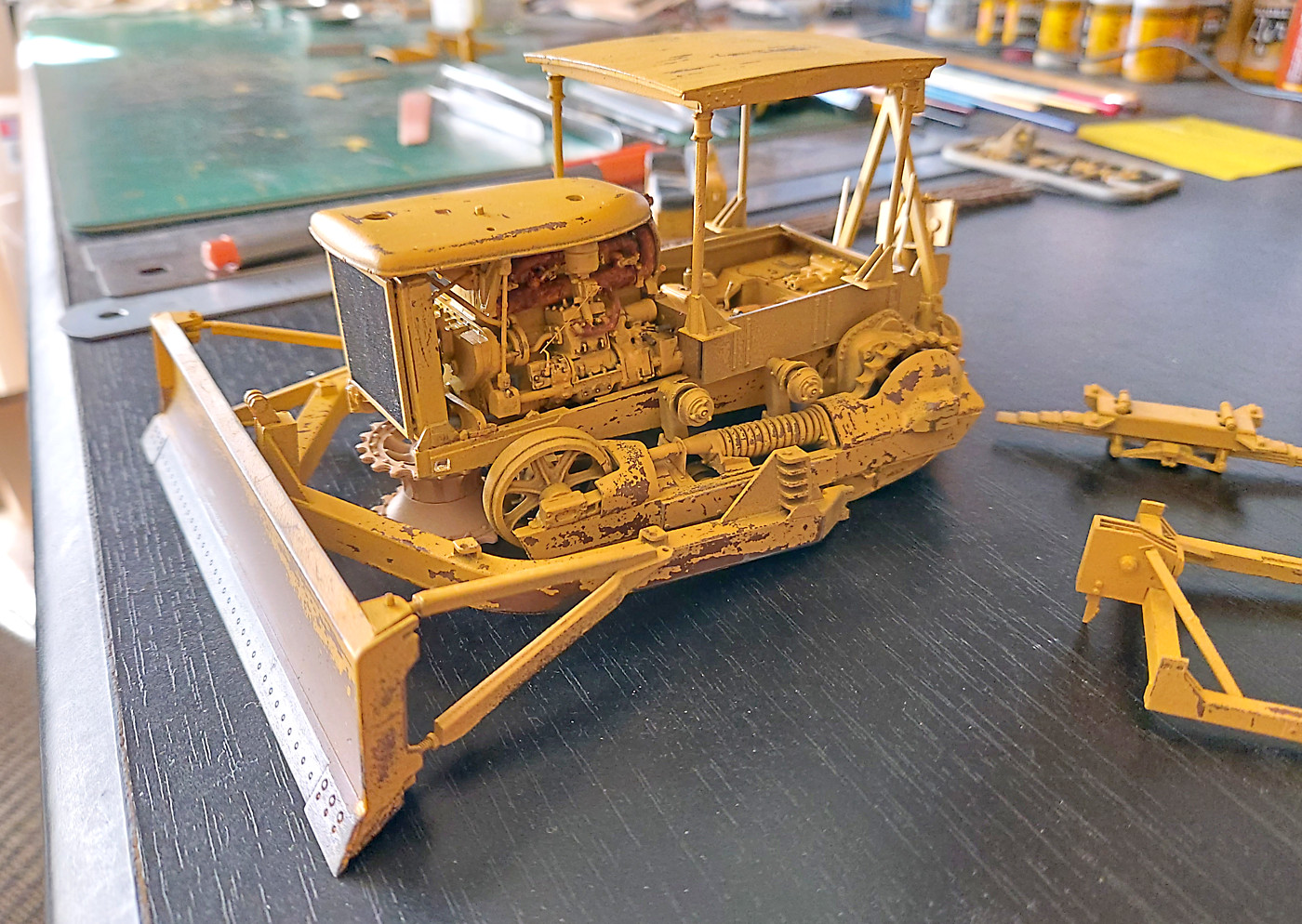
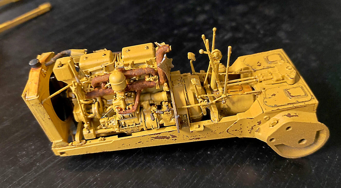
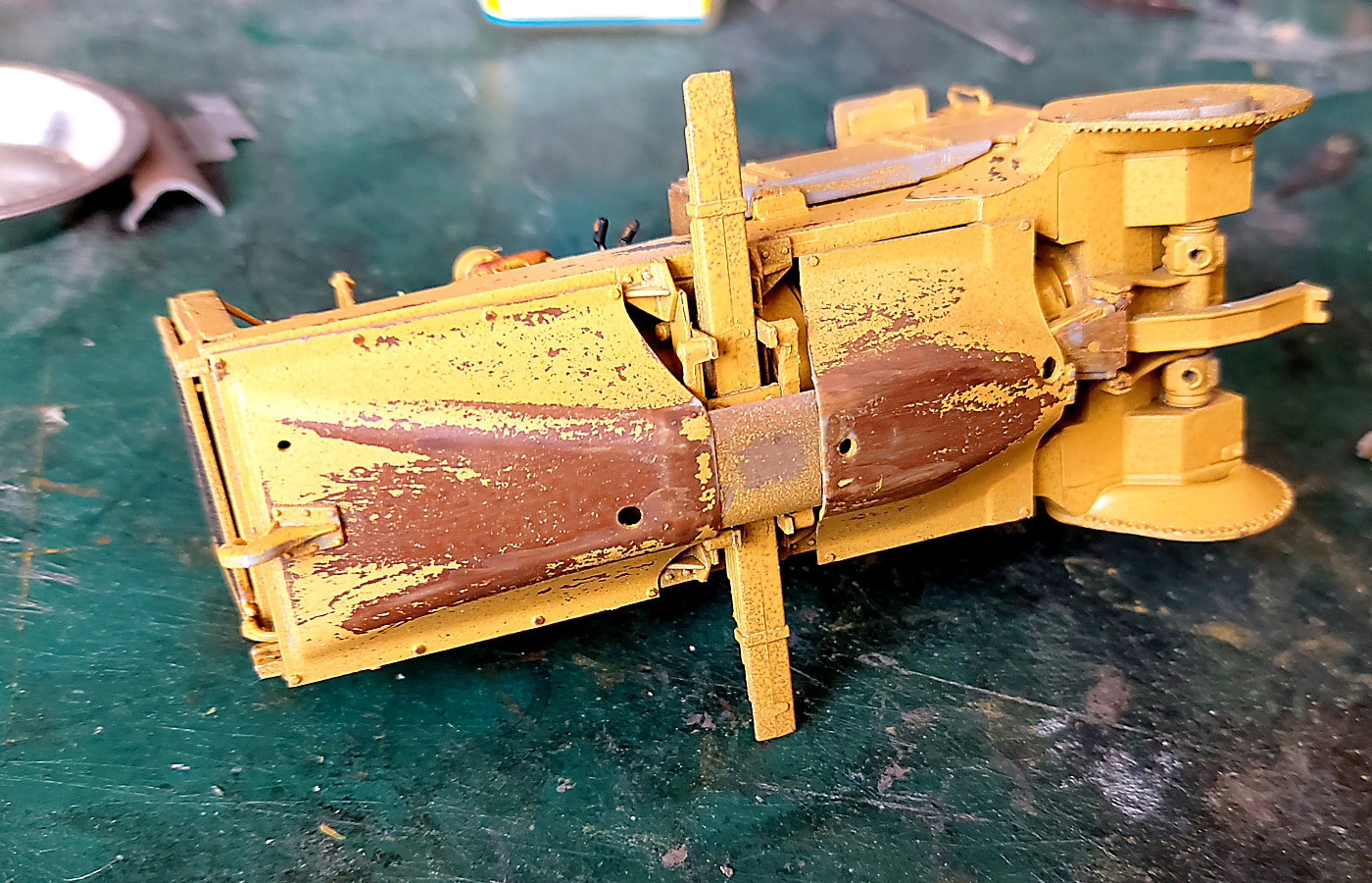
Last chance to see all the gear under the floor boards. The floor goes on next and all the detail and work remains hidden. So sad. But I have the photos!!!
Why do I do these kits so that all the work is hidden?
bruce

5 Likes
all those details look just great after the washing. Sooner or later I have to get one of those…
My two cents on the weathering: Of cause it depends of how new the Caterpillar should be but I think that the wear of the color - particularly around the tracks - does not yet represent the expected pattern. Behind the moving parts and along the tracks where abrasion ought to be highest I suggest to enhance the color wear.
Cheers Michael
My own philosophy is that it’s better to have it and not need / want it, than to need or want it and not have it. Just imagine trying to scratch-build all that detail to show a maintenance scene or for a technical cut-a-way?
Anyways, looking really good!
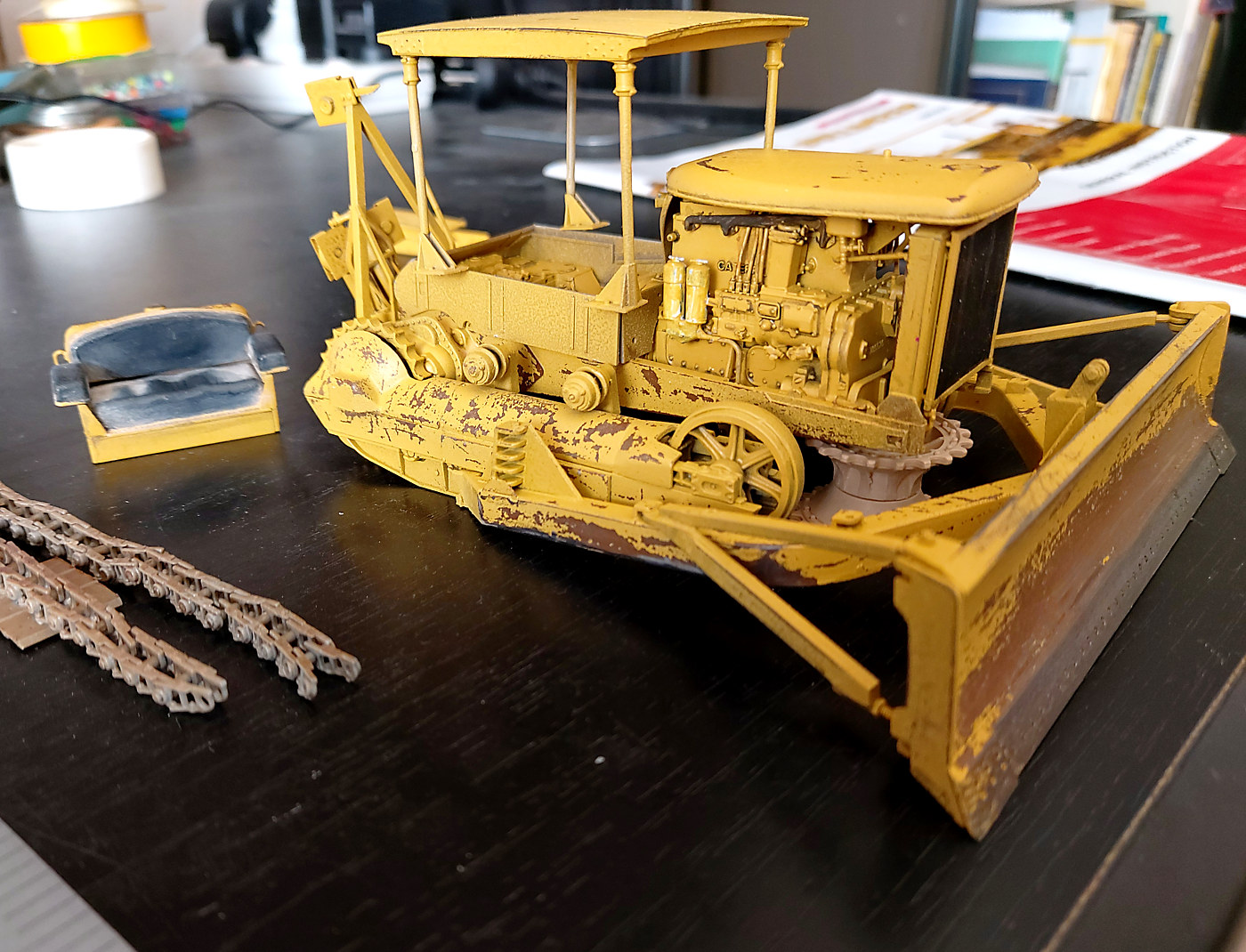
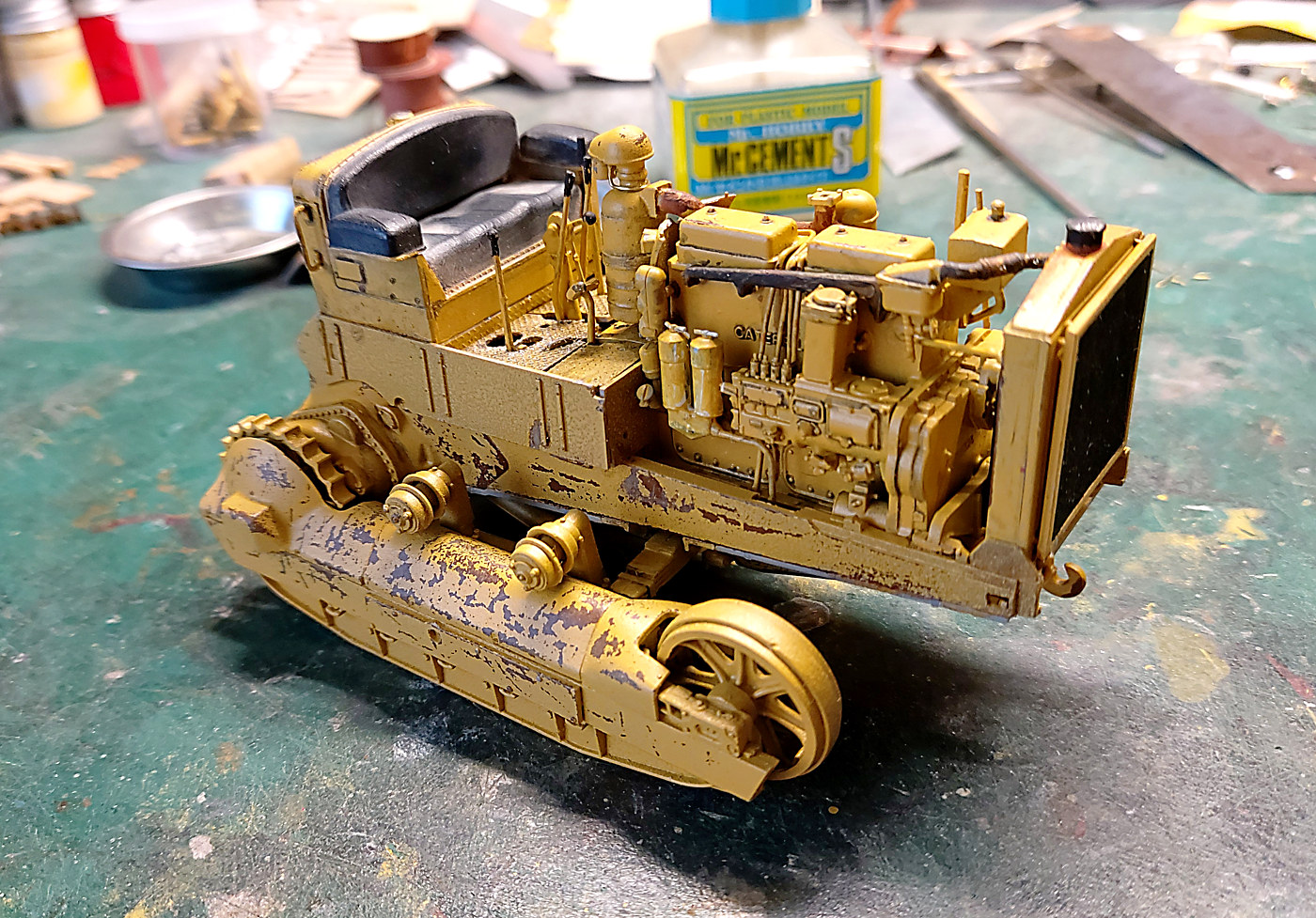
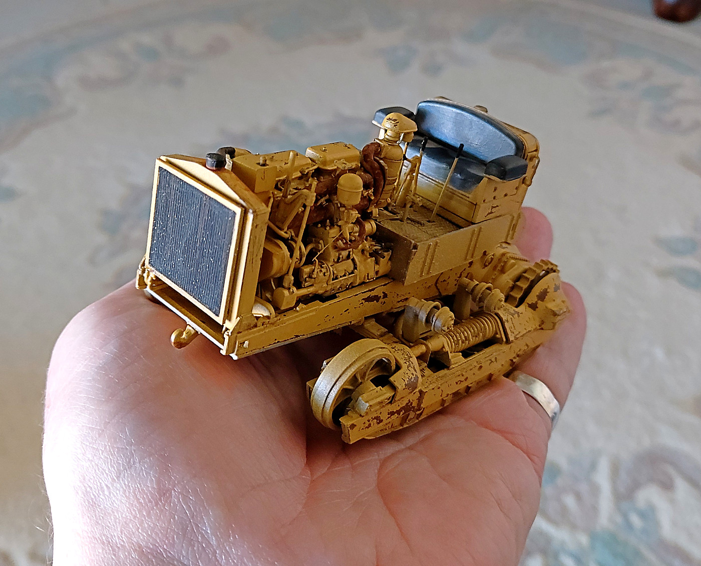
panorama it’s very early days. I’ve chipped parts as I’ve gone along. Then there will be sponge and then oils. The next few steps will be the tracks. So all the wear and tear on parts will be done when I can see where the wear and tear should be.
A couple of images at where I’m at the moment.
bruce

4 Likes
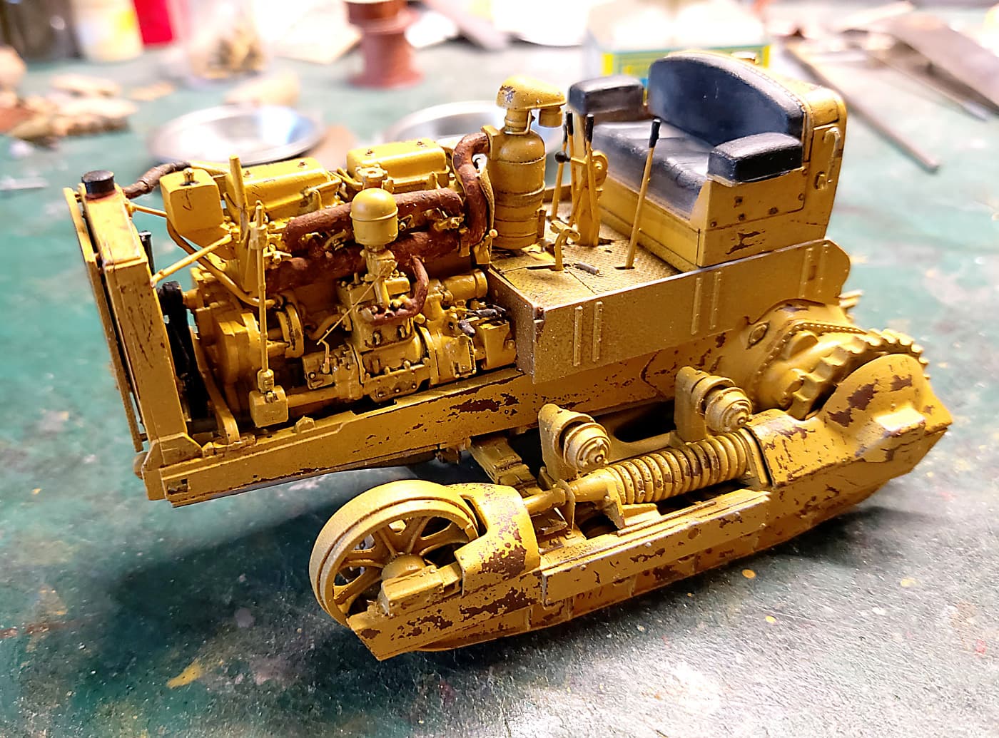
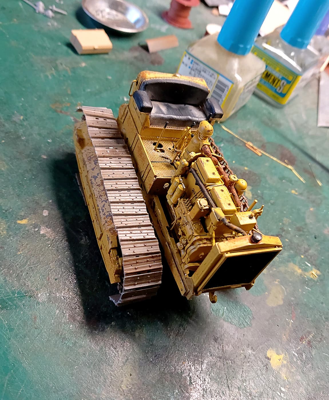
OK today’s update. Now starting to look like a dozer. Now I’ll have a long discussion with the tracks and see if they co-operate!! They aren’t due at this stage of the build but I’m afraid of the consequences if all the detail parts get caught up in a fight between me and the tracks.  I’ve had a trial fit and they seem 1 link short. Both sides. So I have to solve that issue first.
bruce
10 Likes
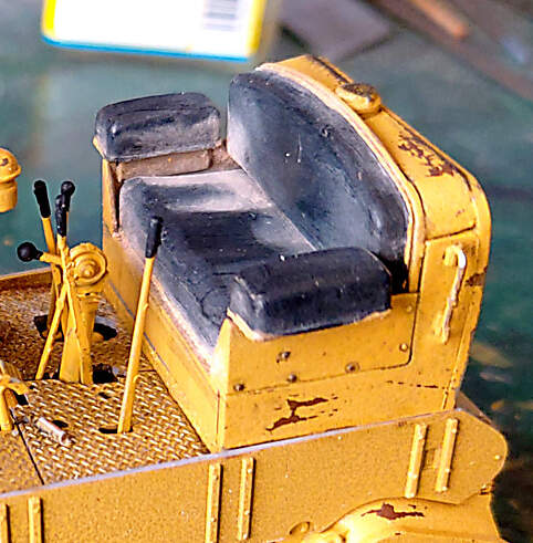
nice update. Anxious to see where this is going. If I just look at the drivers seat I suppose it will be a show.
Thanks panorama. The seat an easy job.  I use cheap tube acrylic black. When it dries I polish the worn areas with a soft cloth. Then for the dust I use makeup. Nick if from the wife? Nah I have a collection of makeup colours. Makeup is a bit ‘sticky’ and holds well. If you handle it and it comes off it’s an easy fix with more makeup. I’ve never given it a clear coat so I can’t say what would happen.
I may tackle installing the tracks today so pray for me.
bruce
4 Likes
Looking really nice Bruce - Godspeed with the tracks .
OK an afternoon looking at the tracks.
I hit a couple of issues. I had assembled the chain/link section when I started the kit. So I had it ready to go. First I tried it in place. OOPS. They are, yes both sides, about 2mm short. Darn.  What to do. There are NO spares in the kit.
So plan B. I attached the chain/link to the dozer and glued it in place. Making sure I had a bit of sag along the top. NOTE to anyone building this kit. The sprocket teeth wont fit, without force, into the chain/links. So file the down the teeth a wee bit, ie narrow the teeth.
I now dealt with the short length by making sure the non join was underneath. A small piece of cotton through the links and tied tight almost got me a fit. But the danger was breaking a link. I’ll hide this on the diorama. (I have broken one link by pulling too tight. Be careful they are fragile).
Then I glued on one by one the pads. Note my rear pads aren’t real neat. They’ll be removed and reapplied later. I’ve only done the top of one side so far. I used slow cement so I can move around the pads to get them neat.
Apart from coming up short on the length and the wide teeth no other real issues.
I have no idea why my tracks aren’t long enough. Other builders have said much the same so I was aware of the problem but still got caught.
Dirt and weathering will do a lot of hiding!
bruce
s
.
4 Likes
Too bad you can’t adjust the track tension like on the 1:1 one…
https://www.youtube.com/watch?v=GOE4QKZO9nQ
(the featured dozer is a D6 )
On a side note, here’s a 1941 D7 in action …in 2014 !
https://www.youtube.com/watch?v=_IlHy1eQljI
H.P.
The fix if there was one is not easy. One has to assemble the tracks first. Then in steps 34 and 43 cutoff and move the sprocket pin forward say 1mm. Then 39 and 49 have to go back 1mm. Then the spring and shrouds have to messed with to account for the new shorter lengths. A giant mess.
Option two is add one more link from one side and show the other side track as either thrown or under maintenance.
Frenchy thanks for the links. The second one is the kit almost down to the last rivet. Great info. You certainly have to know which level to pull and when.
Tank_1812 thanks for the feedback. I think I have another solution. Not that I’m going back to see if it works!!! You obviously have the instructions. So here’s my thoughts. Step,s 38, (47), requires you to cut part C45 to slip the PE on. (I did on one and split the PE on the other. Then twist and slip the PE over part C45. Splitting the PE was much easier). So when you cut part C45 trim 1mm off the rear of the shaft. That should bring the idler wheel forward 1mm. (1mm top and 1mm bottom should equal 2mm!). It ‘should’ be easy then to trim the idler wheel so it moves 1mm forward. In fact if I remember correctly it was a bit of a guess how far to push it in.
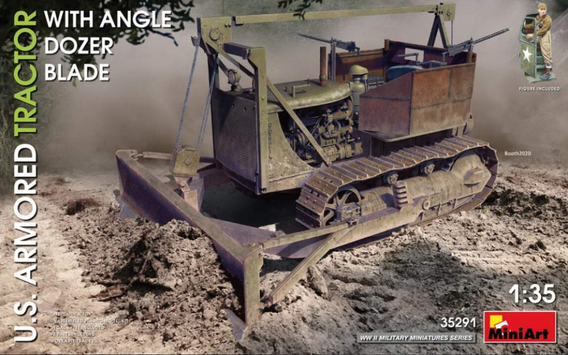
I’m almost, just almost, about to pull the trigger on MiniArt’s #35291. It’s the armored Army version of the same kit.
Again thanks for the feedback. Much appreciated.
bruce
2 Likes
That’s a great idea if you get the second kit. With the track already made you should be able to see how far to push the idler wheel in at that step.
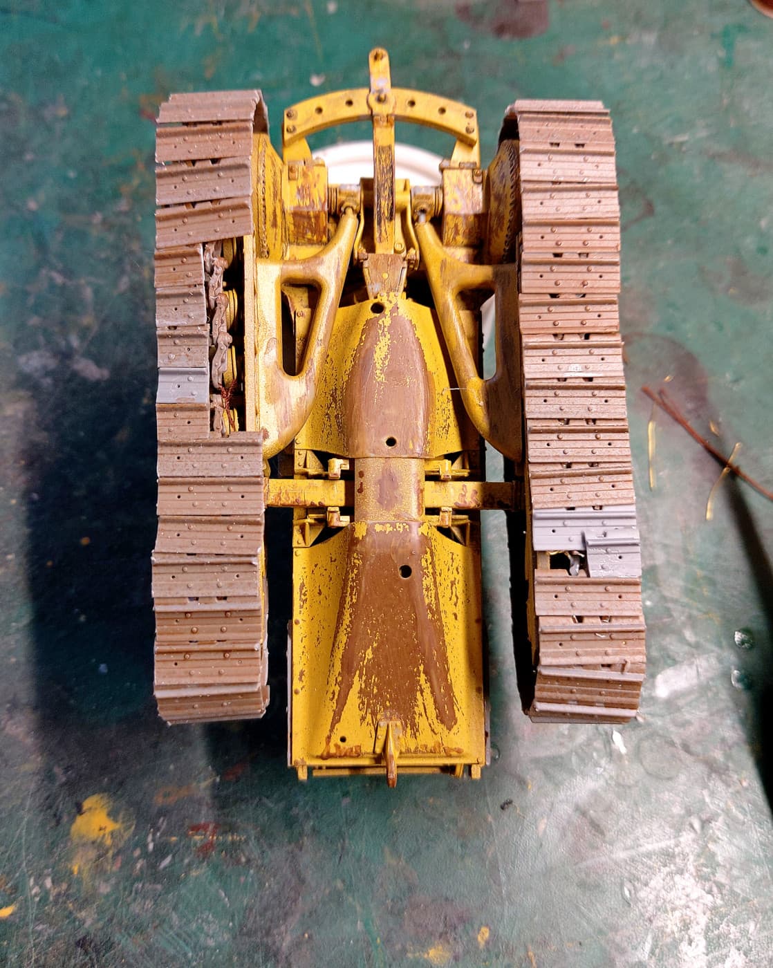
OK now I’m getting cranky. My chain links on both sides were about 1mm short of joining. No worries I put the join at the bottom I will hide it. BUT now I’ve all but glued on the pads and found I’m a pad+ short on each side. Who counted the pads? Not me. I just assumed the pads tallied with the links. Glued them on using the guide pins. I didn’t miss any pins. With a dozen pads to go I could see there wasn’t going to be enough. So given if I hadn’t the missing 1mm and had joined the chain link ok I would still have been a pad+ short on both sides.
Excuse the wobbly tracks. It’s going on a diorama so wasn’t really too fussy with their alignment. Maybe I’ll tear them off and straighten them. They look bad in the photo. Yup next job to rip a few off and straighten them.
Answer was to cut several pads in half and glue them to the outside. Grrrrrrrrrr.
bruce
6 Likes