Minart kit #38022 build summary.
For a few decades I was a model railroader. Still am. Then suffering burnout I went looking on the internet for some inspiration and came across all the wonderful 1/35 scale dioramas. So as they say the rest is history.
One of my first kits purchased was MinArts kit #38022, ( I had a mini stash!!). So onto the web and did some research. I soon found that MiniArt’s Bulldozers came with a reputation. So for 12 months I avoided the Bulldozer. Then it got the better of me. So here I am finished and wanting to share my experience with this kit. One YouTube, 5 part, build had issues. It’s a different version and I never had the same issues. But it certainly gave me much to think about. (Will Pattison’s build on YouTube).
First let my address a common belief in MiniArt’s “bad plastic”. I’ve now built several MiniArt kits. Never had an issue with the plastic. I believe they change suppliers and problem solved. Maybe some older kits are still on shelves. But I’ve had no issues.
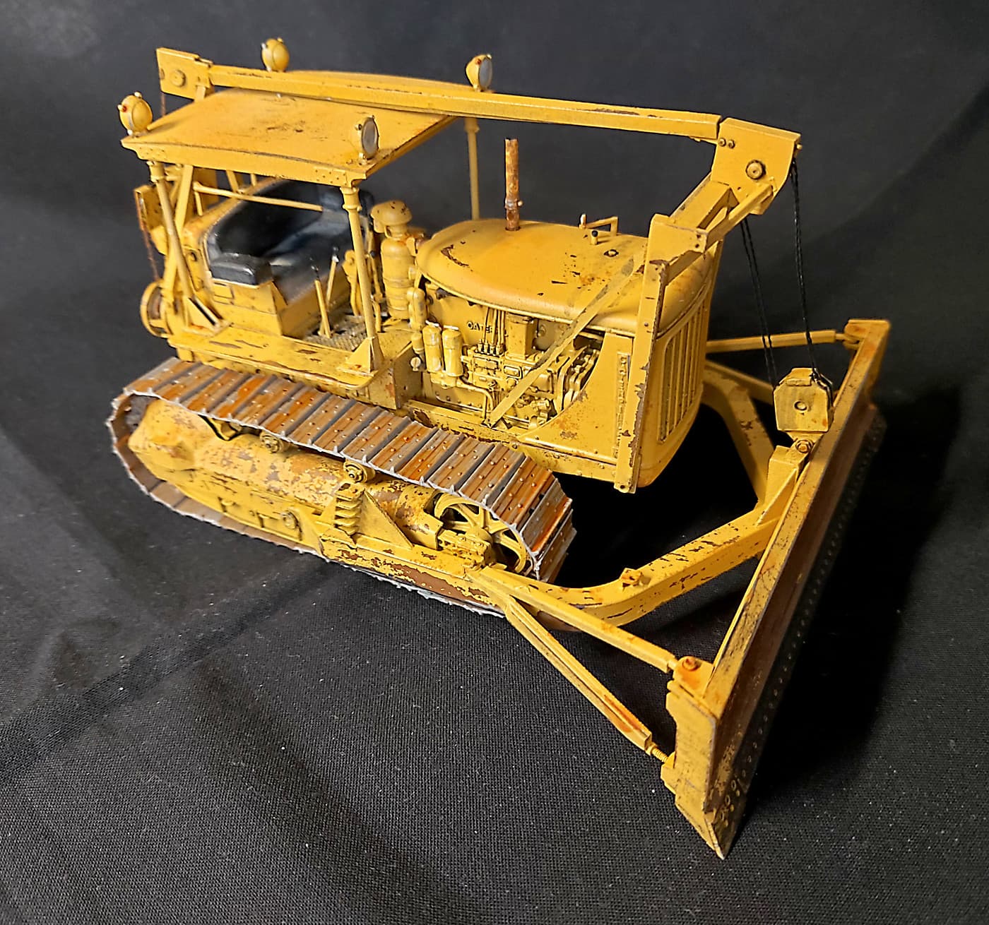
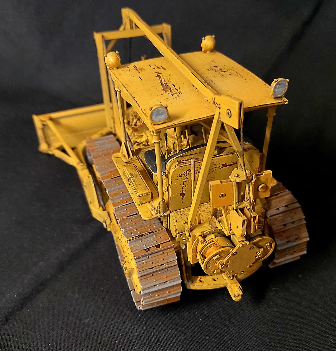
There are several Bulldozers in MinArt’s catalogue. Kit #38022 is an early cable civilian version. Yellow of coarse.
So some thoughts on the build. I’ll list step numbers for those that maybe considering this kit.
Overall the instructions are typical of most kits. I found them no better or worse than the likes of RFM. Read way ahead and do a lot of dry fitting. No written instructions I guess because we all talk different languages.
The engine has a LOT of small parts. But by itself would make a great model.
Step 12. Part C82. I didn’t glue this in place because it needs a specific location later on.
Step 14. Make sure part C73 is vertical or you’ll be sorry later.
Step 16. Make sure part B29 is vertical. It’s the starter shaft for the pony motor and the handle needs to line up with the hole in the hood.
Step 17. C17 is the only part in the kit I broke getting it off the sprue.
Step 21. Make sure the back of the transmission goes well into the hole in part B17. Sub assembly from step 20. I filed the hole a wee bit bigger.
Step 25. PE11 has to go through a hole in part B23. Open up this hole as it’s too small for PE11 to fit through.
Step 29. Note the orientation of the slot on part C58. At this stage you will find out if you have everything in place as all the levers need to go through the floor. Don’t be tempted to glue all the floor together first. It wont work!
Steps 33 through to 37. (42 to 46). Take your time and make sure everything is square. It’s not hard to put together but it’s harder to get it all square.
IMPORTANT. Step 38. Part D15 should read part Da15. The instructions ask you to cut part C45. This is necessary to install PE8 x 2. This part also plays an important role in installing the tracks. MiniArt give NO spare track links or pads. A it is I found the tracks came up short by just a few mm. I was aware of this problem and still came up short. My solution for “next time” is once you cut part C45, (C44), is to take off an additional 1-2mm. It’s not an exact measurement and will depend on how well you build the tracks. Now this will affect step 39, (49). Make sure you push the idler wheel well into the assembly. It may require a bit of trimming. You need to have the idler wheel about 1-2mm further in than the kit suggests. Make sure the upper idler wheels, 2 a side, are vertical. Bottom corner of page 9 & 10.
Step 40. I left off part A6. Just because I never had the heart to cover up the working spring. Otherwise step 40 to 50 is a repeat of the other side. Remember to trim part C44.
Step 53. I suggest replacing part C49 with a piece of clear sprue from the scrap box.
Step 57. Parts E18 and E19 need to be well in front of the grill. My locating pins on both parts were miss moulded and the locating pints were missing. The curve on the back of E18 and E19 DONOT meet with the curve coming down from parts B5 & B4. See step 68 for how they should look.
Step 59. I found it easier to glue parts He5 to He8 & He9 before gluing to sub assembly from step 58.
Step 60 & 61, I found De4, De5 all but impossible to install. Instead I put a rod right through. See step 63. BUT that never worked because it made installing the cable impossible. See the note at the end for my solution that I ended up using.
Step 64. Parts De9 should read Df9.
Step 65. Make sure E9 is installed vertically. The instructions are vague. The images of a complete model on the back page are WRONG. This part needs to be vertical as per the instructions colour illustrations.
NOTE. I never wanted a ‘working’ model. Thus I glued everything rather than trying to get it all to work.
Step ? Page 14. The tracks. Like all tracks they can be a PITA. Take your time. I made all the links/chain. Then installed the pads AFTER I installed the links/chain onto the bulldozer and glued it in place. My theory being that I could hide the ooops under the bulldozer. Installing the pads on all the pins is about as good as picking all the lottery numbers. Just make them neat. (I emailed MiniArt about the issue. They never hesitated to send me spare parts. But this shouldn’t be necessary if you are more careful than I was).
Step 74. Bottom left step of the page they ask you to insert E15 between E16 and E17. With NO glue. Good luck with that. My suggestion is to glue part E15 to E12 first. Then install E16 and E17 around E15. I glued everything as I wasn’t interested in a working model. Part E12 has 38 sprue gates. Enjoy!! Parts De3 go inside the marks. I think!! I glued mine to the outside of the marks and struggled with Step 70 and 71 later on. I think going inside the marks will be the correct location. Test fit first. Maybe I interpreted the instructions wrong. See step 75. Check and recheck.
Step 76. The block. This needs to be wired first or you will never get the cable/thread through. I assembled mine as per the instructions. I never could get the treads through. I pulled the block off and disassembled it. Twice! Threaded the cable and started again. Almost impossible to keep the glue off the thread/cable. Thread also never looked taut. In the end I gave up and consigned the tread to the trash bin. I found some 34 gauge wire in my stash. Twisted my own cables. Made them as straight as possible. Cut to length and super glued them in. Next time I will use metal cable everywhere. All cut to length and straight. Then super glued in place.
Site member Frenchy gave me this link which has been a gem. Caterpillar D7 1T 1941 Still at work - YouTube
All up it’s a great kit. Yes a few oops moments. But aren’t all kits like that? It took me about 55 hours to build. (Weathering is an on going process). I found the kit no more difficult than my RFM interior builds. I never found it the beast I was dreading. I enjoyed the build so much that I’ve ordered the military versions. Kit # 35291. The engine alone would make a great diorama.
I would like to thank everyone for their feedback.
bruce


 Pulled the thread and binned it. Now coming from model railroading you would think I had a stack of suitable wire. Nope. So into the parts draws and I dug out a roll of 34 gauge wire. Then twisted it and twisted it. Bingo. Looks good enough and holds it’s shape. A bit of superglue and I’m back in business. (looking at the image there isn’t enough twists/strands. But I figure a lot of grease will fix that. Besides the image is WAY bigger than the wire).