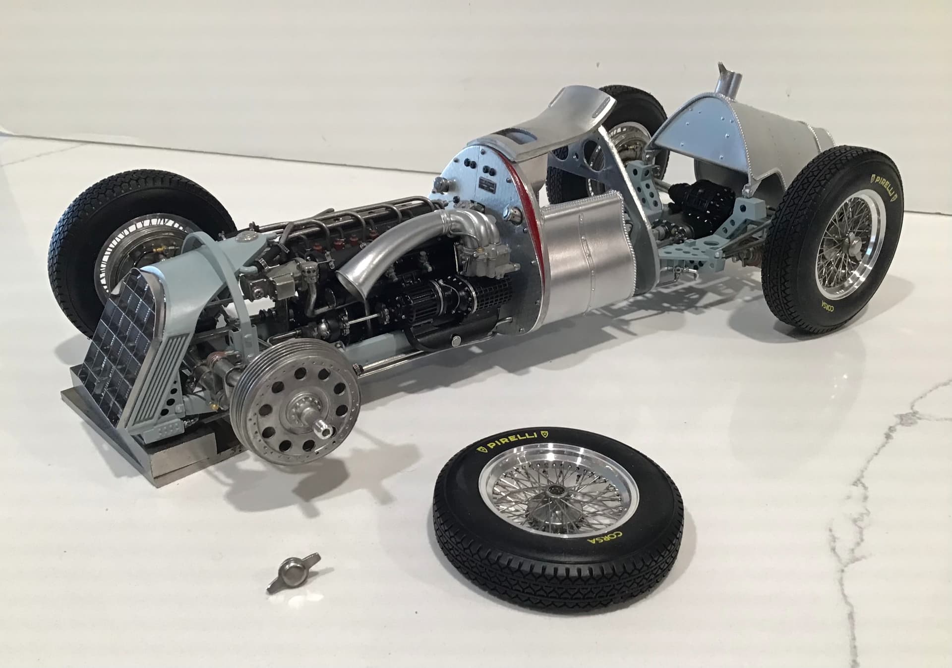
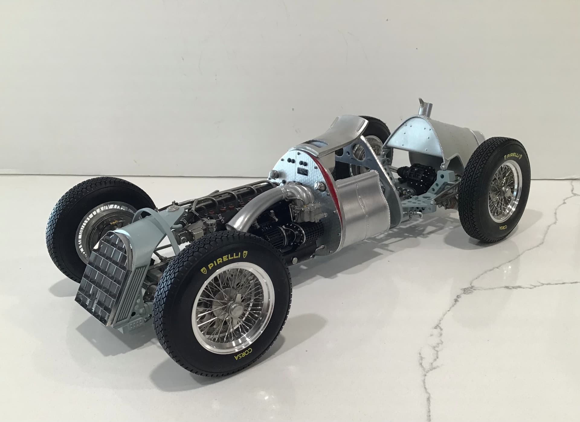
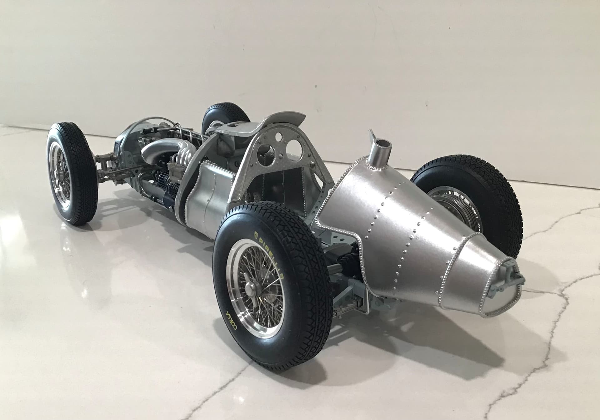
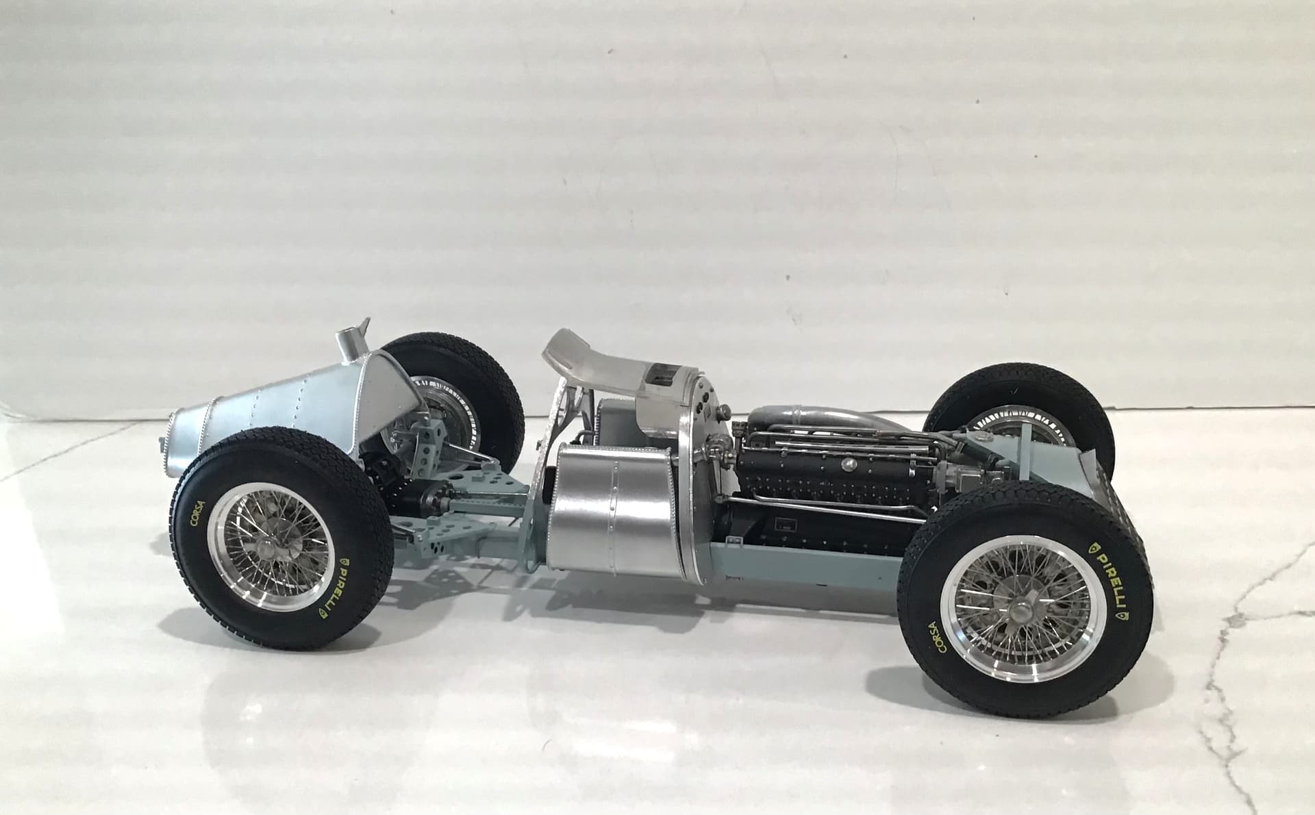
Time to build some wheels. Each wheel is made up of 146 pieces .
MFH supply a turned aluminum rim with 72 pre drilled holes in two bands - an inboard band of 24 holes and an outboard band of 48 .
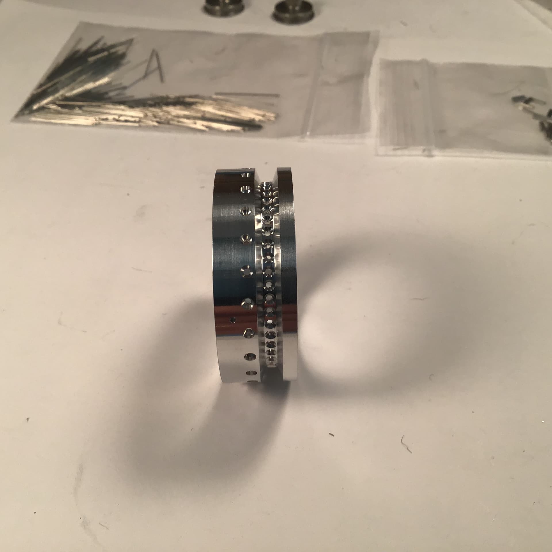
The hub is supplied in cast white metal with dimples marking the location of 72 holes which must be drilled while in the building fixture using the rim as a guide. Also supplied are 72 wire spokes and 72 pieces of tiny tubing to represent the nipples .
The building fixture is cast white metal with dimples around the perimeter 90 degrees apart which must be drilled for 4 tiny screws which clamp the rim in place .
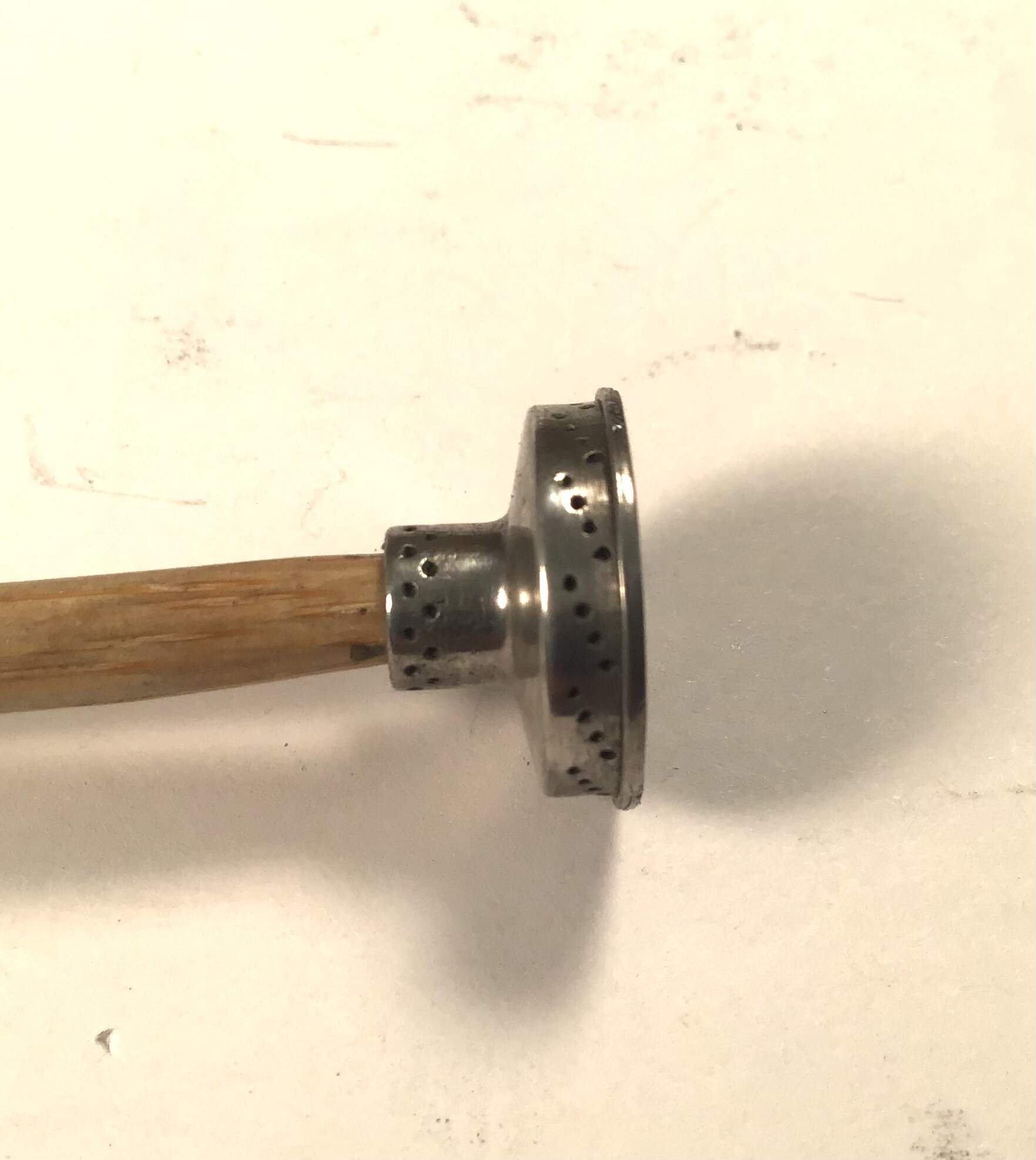
There is a reference line scribed on the fixture that the valve stem hole aligns with and a key which corresponds with a slot in the back of the hub. This is to assure that the hub is indexed properly with the holes in the rim .
A piece of clear Teflon tube is inserted in the outboard end of the hub to prevent the spokes from protruding into the axle area . This tube is removed after the wheel is assembled. The hub is held in place on the fixture by a screw / washer.
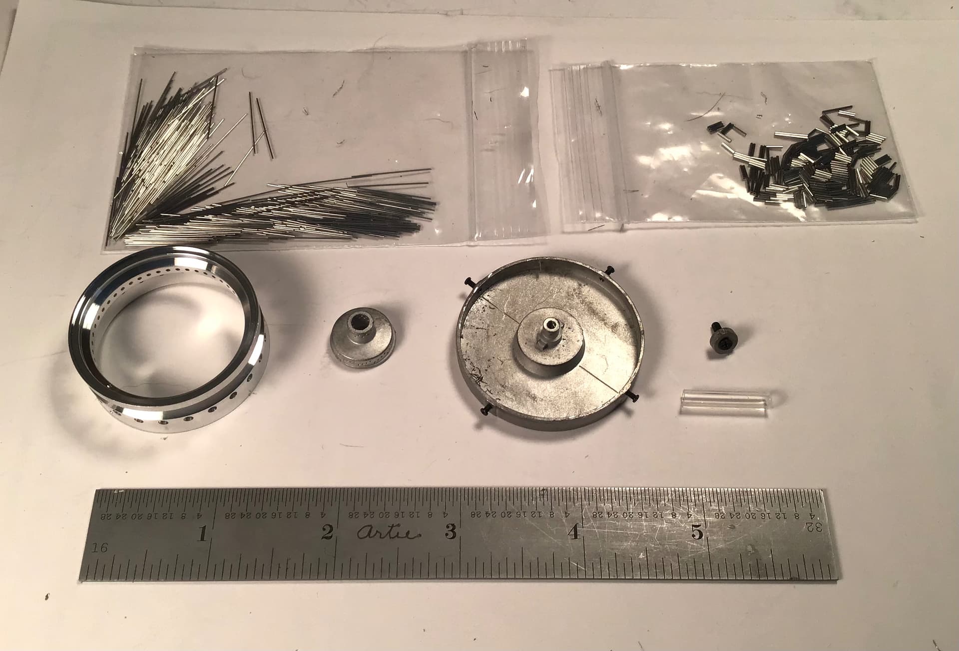
The hub has an inboard large diameter section with 12 groups of 4 dimples . In each group of 4 the dimples are staggered outward . In the small diameter outer portion there are two bands of twelve dimples.
I turned a mandrel out of a piece of bronze rod to hold the hubs in the lathe to clean up the castings with 800 grit silicone carbide before polishing with Blue Magic .
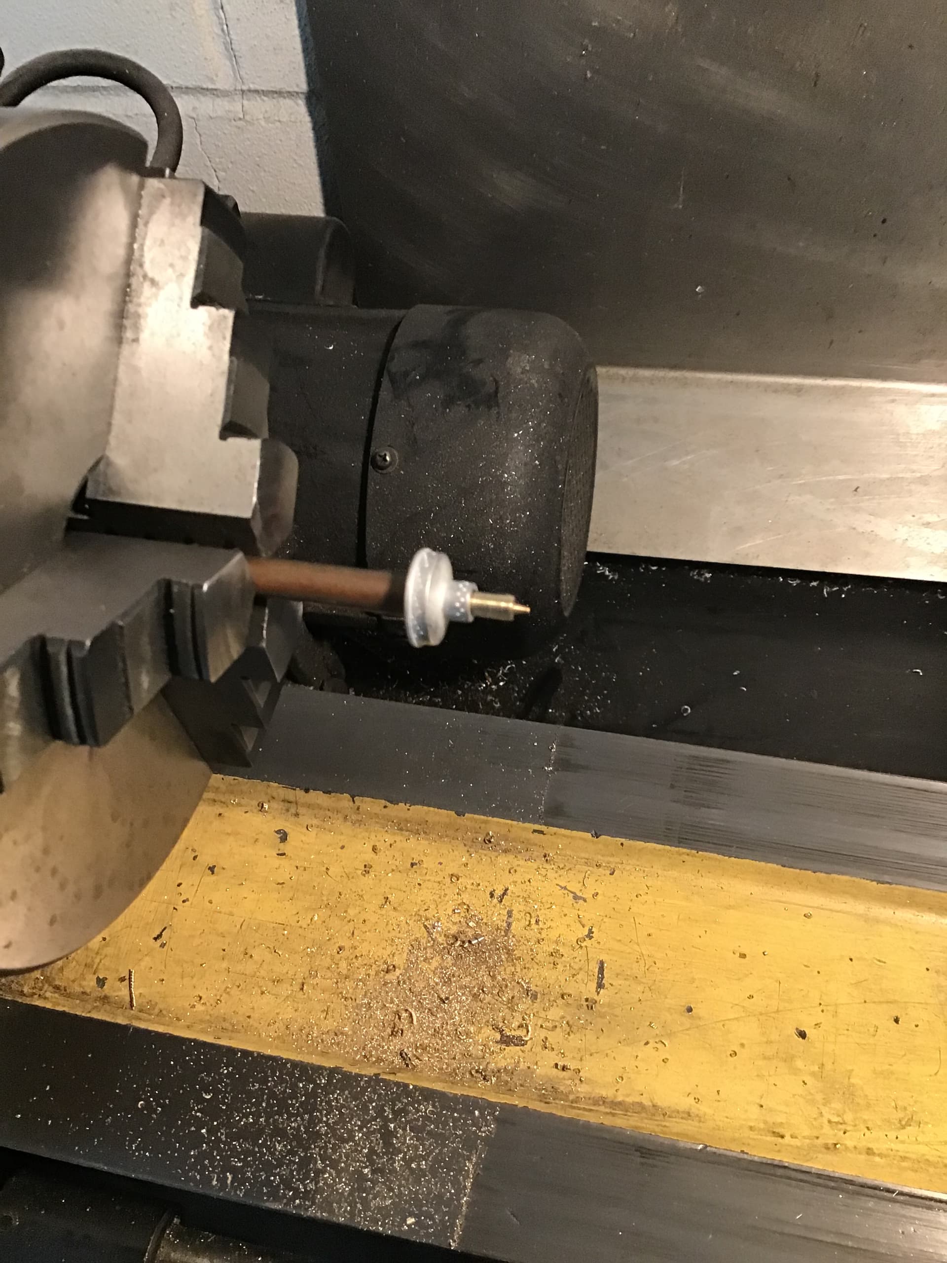
After polishing the hubs we’re given a coat of clear gloss lacquer.
Very clear instructions ( pictures really ) but requires study and attention.
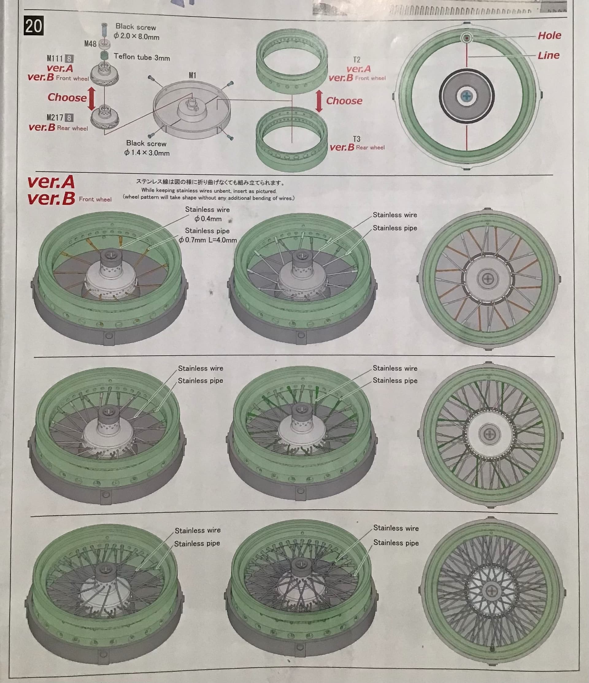
With all in the fixture the drilling begins for the inboard most set of 12 spokes .

The first row of spokes in place , inboard ends fastened to the hub with CA. Rim ends insert in the inboard band of holes
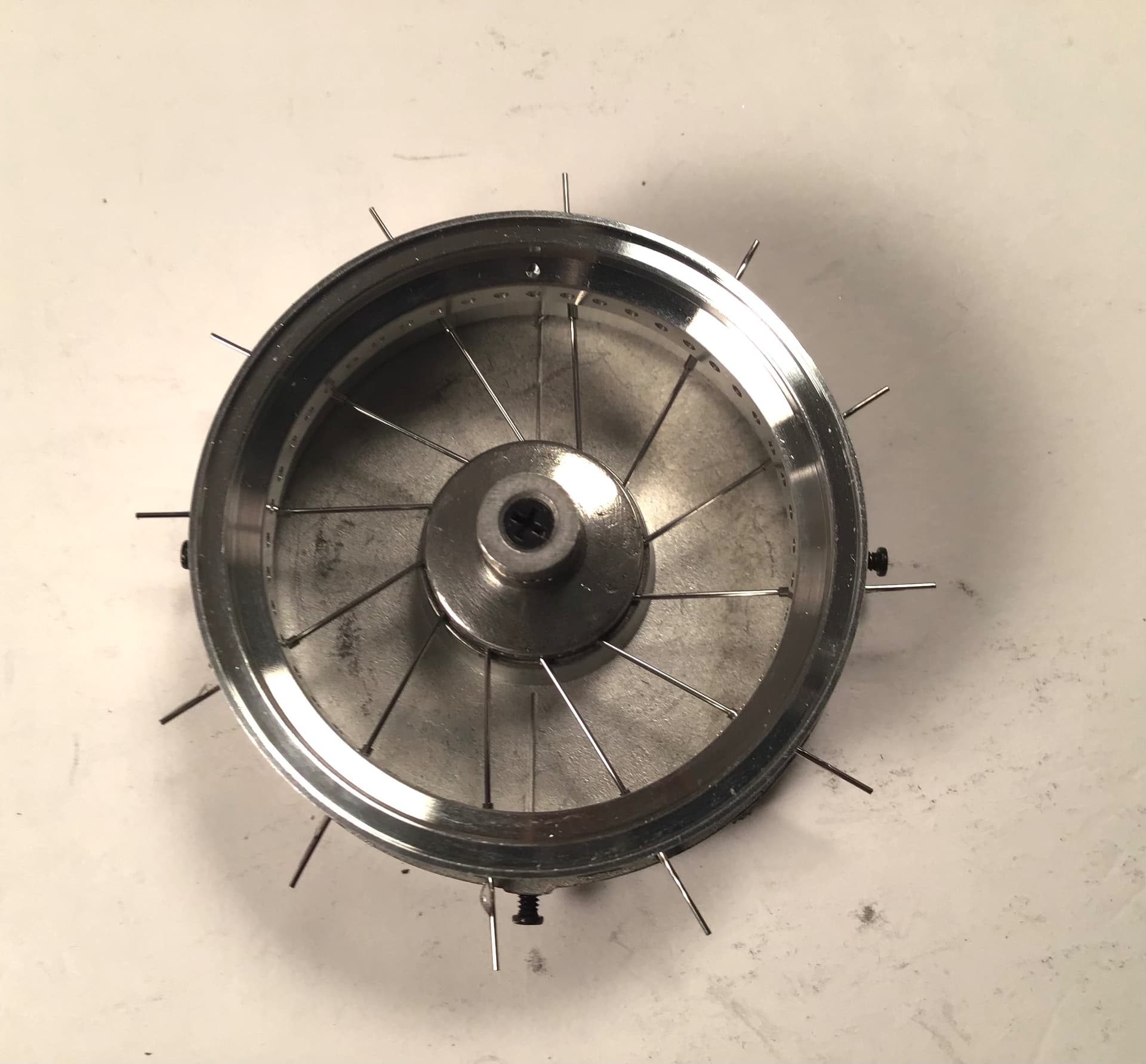
The tiny tubes that represent the nipples are slid on over the ends of the spokes and cemented with CA . There is no positive stop on these for the amount protruding from the rim so I just eyeballed it . In hindsight I suppose a jig could be made . The holes in the rim then had a drop of epoxy placed at each spoke . After curing the excess spokes were trimmed off with an abrasive cutoff wheel in the Dremel.
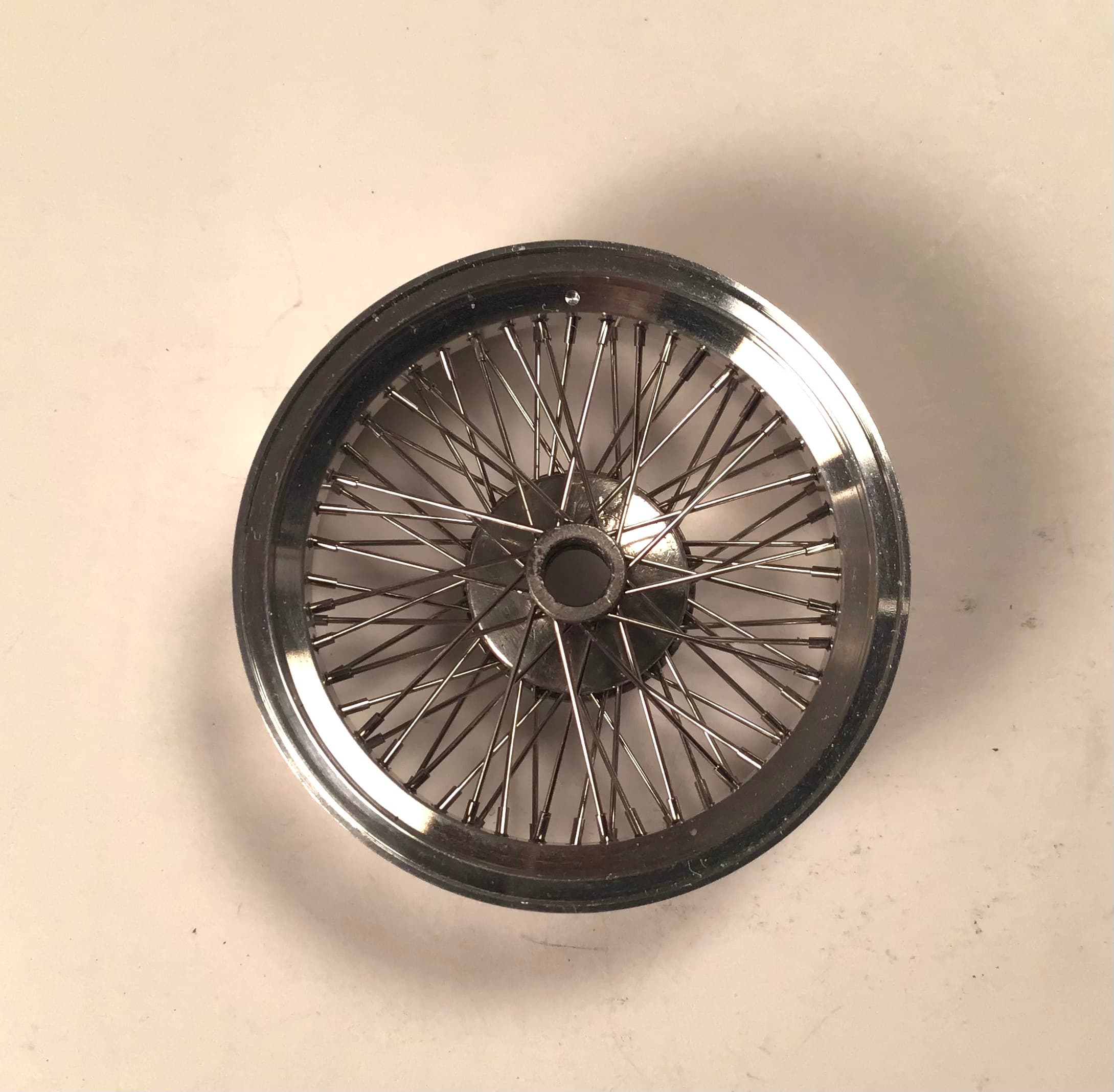
Second row…
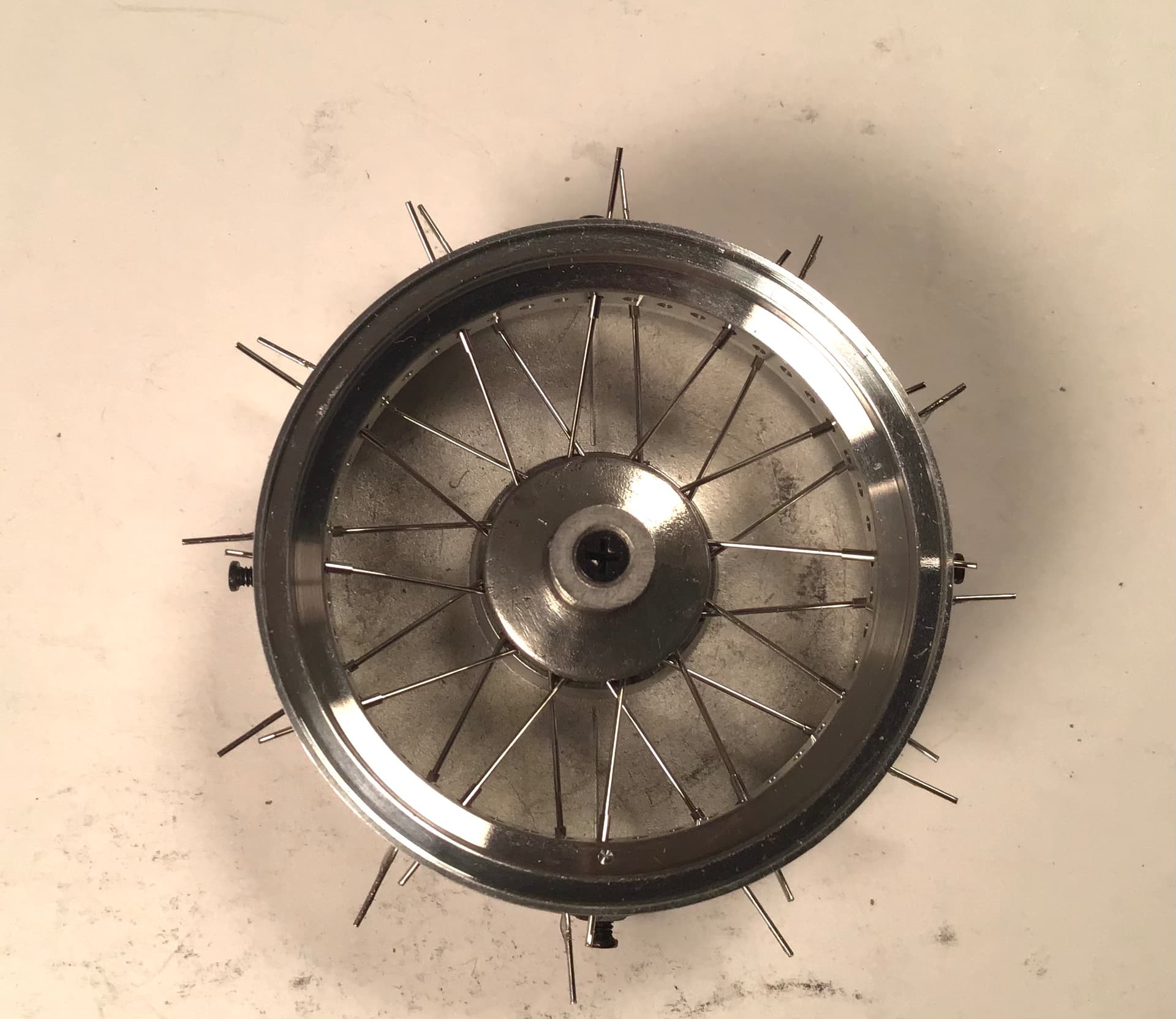
Note that the succeeding row spokes lead in the opposite direction and also enter the rim from the outboard band of holes. This provides triangulation both radially and axially for stability. Another thing to note - in wheel building terms the pairs are said to cross once . Look at the hub ends and it can be seen . When we get to the last two rows at the small end of the hub the pattern will cross twice .
Third row and back to the inboard band of holes in the rim … this will fill all 24 holes in the inboard band of holes . All succeeding rows will now use the outboard band of holes in the rim .
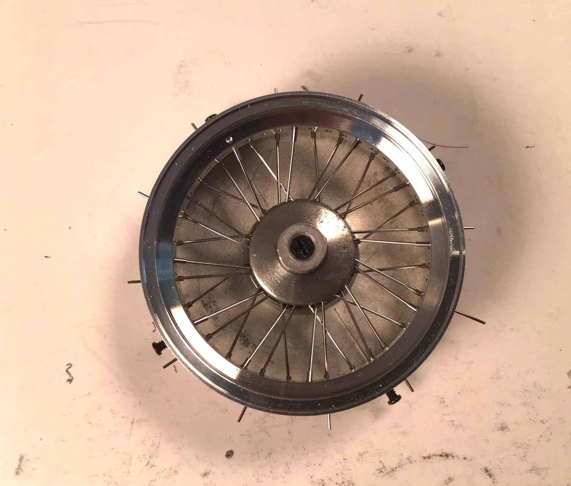
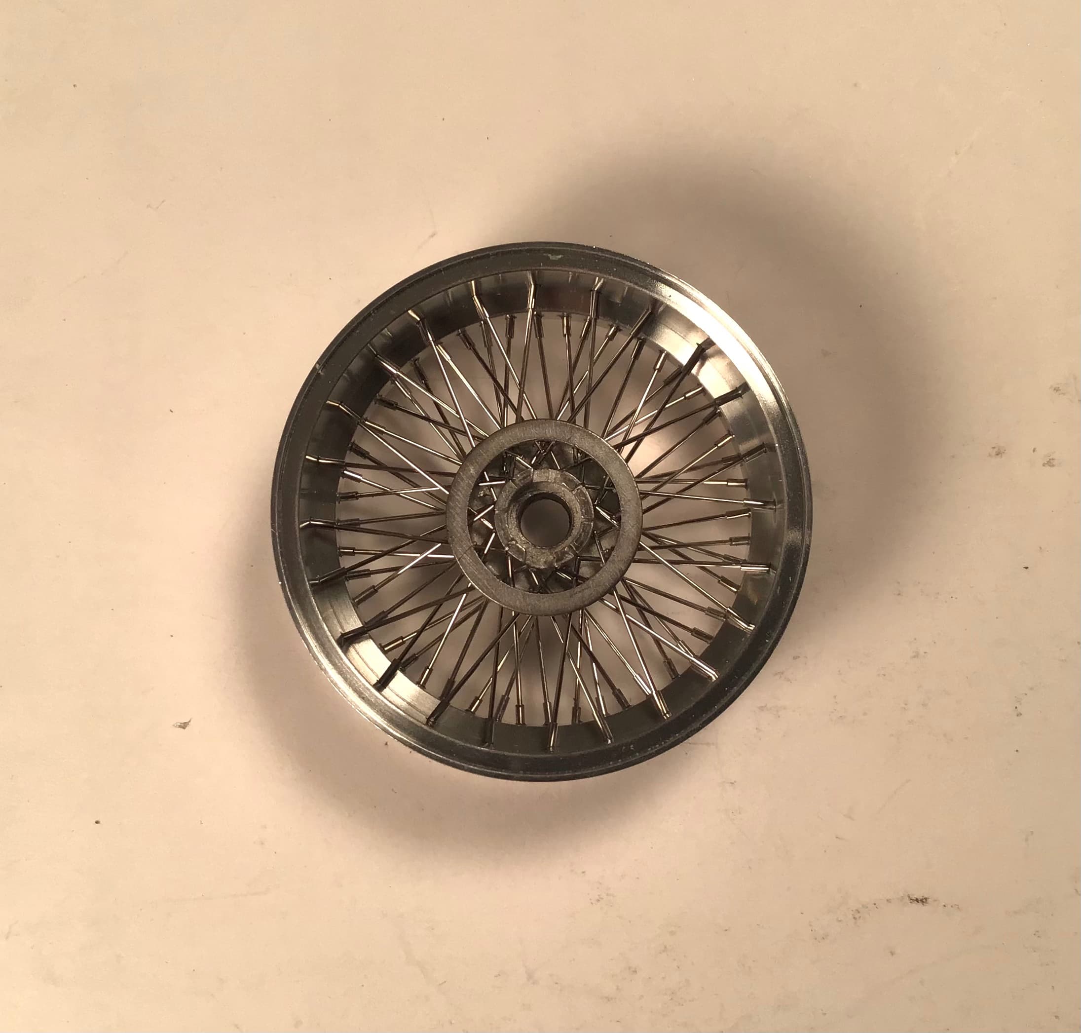
Fourth row … this will complete the spokes that enter the large diameter portion of the hub.
Fifth row and the first of the spokes leading to the small diameter portion of the hub.
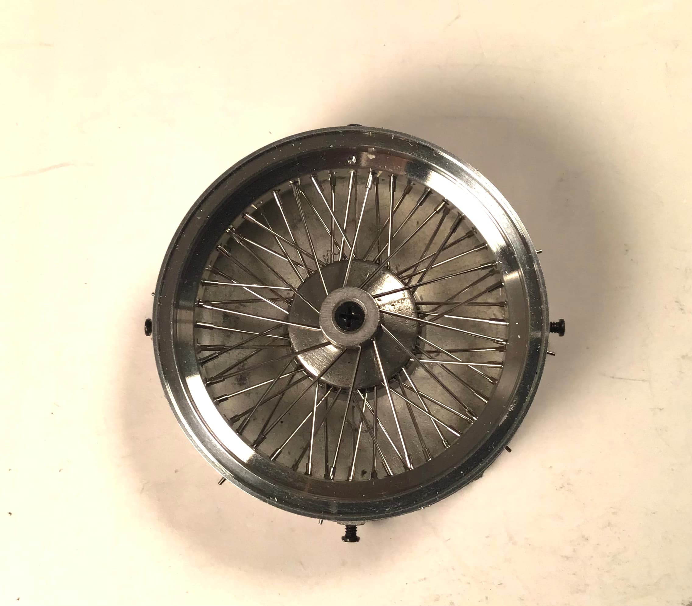
And the final sixth row …
Here it can be seen that each of these outer spokes cross two others .
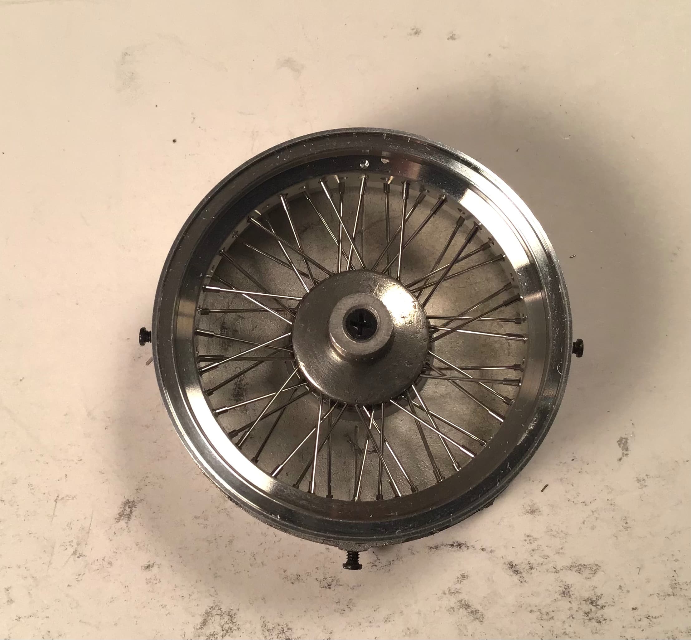
Here is the back side …
Just like the real thing , all this spindly stuff becomes an amazingly strong and rigid structure.
As anyone may surmise , the drilling gets a bit tedious.
I have one more row to go on my second wheel so nearly halfway home . I purchased a dozen # 78 bits figuring 3 per wheel but I may need more . They tend to fail at the chuck and for some of the holes the full length of the bit is needed for reach .
Thanks for looking and as always, all comments welcome.
Cheers- Richard