Here is the completed transmission, I hope it fits! The MIG Engine Oil & Fuel wash set really did a good job I think.
5 Likes
Finally got the transmission in, plumbed in and a few other little pieces around the transmission. Also added the fighting compartment floor.
This was all very hard work. As you may recall, It was very difficult to get the hull floor all lined up properly, and as a result of this, it took hours and hours of filing, sanding and filling to get everything to fit.
Reality is, if you look closely, you’d see what a mess it is, but actually, it doesn’t look too bad at all. I’m not a rivet counter, so it’ll do for me. Off on holiday now to Corfu for three weeks, so there won’t be any posts on this build until at least 27th September.
Stay well everyone.
6 Likes
Doesn’t look like a mess to me! If you look inside my Takom King Tiger the fuel tanks are a mess because it was a real pain getting the engine in. This splayed the fuel tanks slightly so the hull top wouldn’t fit! I had to grind down the inside of the top hull to get it to fit. Fortunately all glued down so no one can see! By contrast your Panther is perfect!
I just got started on RFM’s kit 5019, the Panther Ausf. G with the cutaway hull and turret, about a month ago. Your progress report went a long way in making me think I could pull this off. I finished RFM’s Pzkpfw IV Ausf. J over the winter (about nine months of work). This Panther kit is a greater challenge, no doubt about it. You’ve done a great job and your insights and advice are spot on. RFM has put a lot of detail into this kit but I would underscore your comments about reading ahead in the instructions and not necessarily following the steps to the letter. I have come across several places where there’s just not enough information or warning about how a piece is to be placed so that it matches up properly with a separate sub-assembly. I’ve caught some, but not all, of these omissions.
I also agree with your comments regarding the painting of this kit. The guide provided is pretty basic. I think you’re on the right track with what you are doing. Keep up the great work. I’m looking forward to your return to the workbench after Corfu.
So, i’m back from Greece, actually, i have been for about three weeks now, and have made some progress.
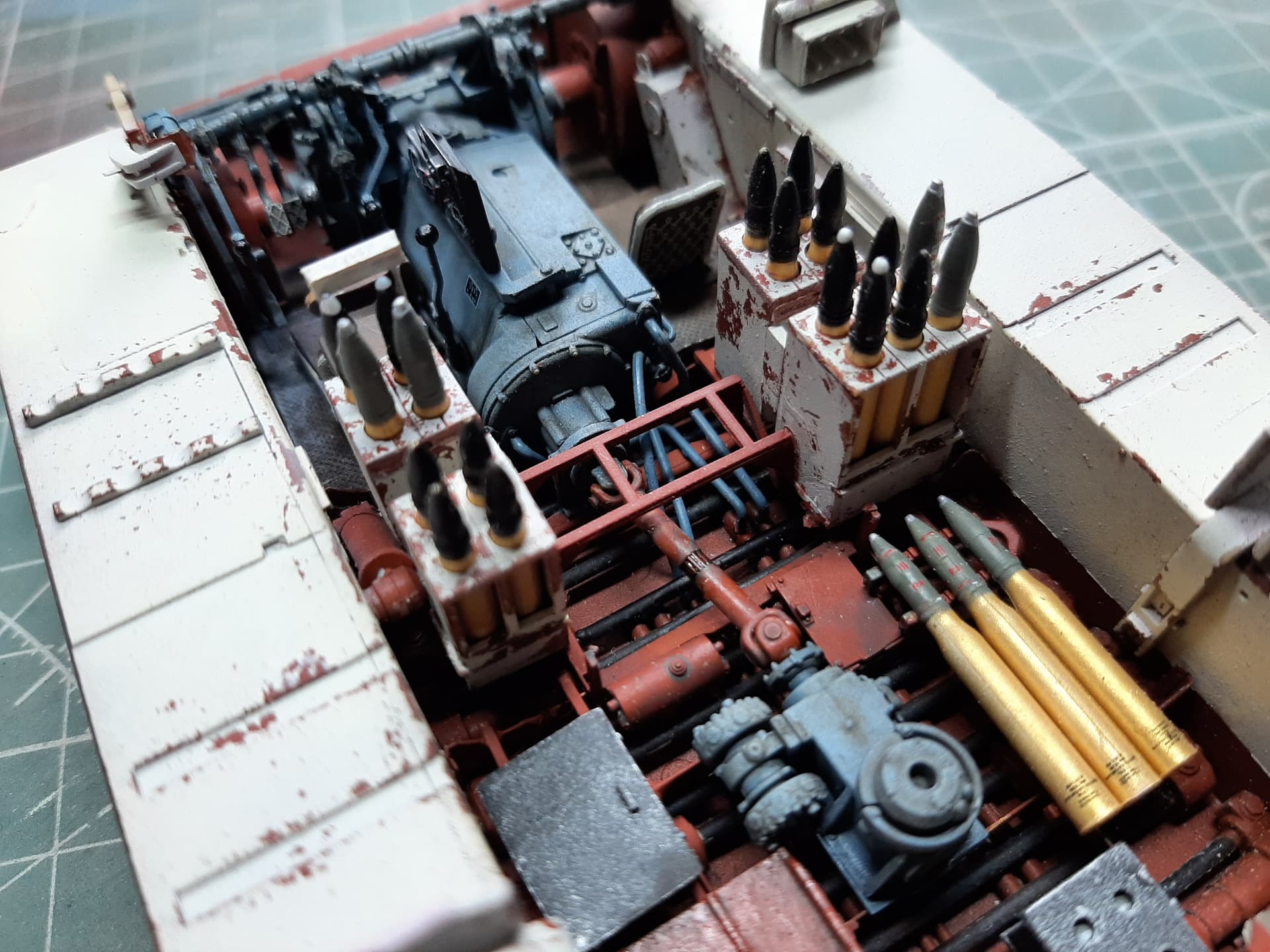
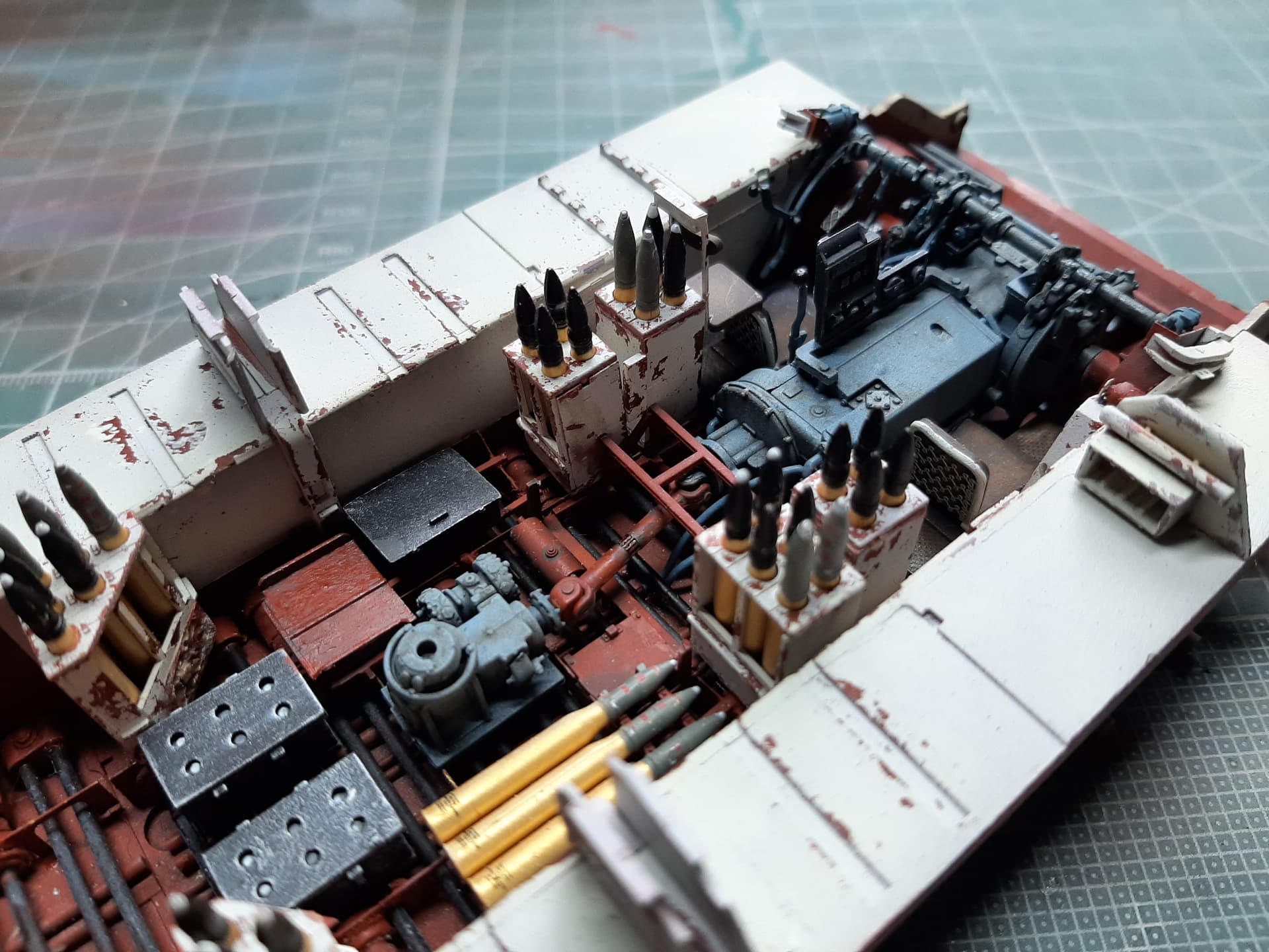
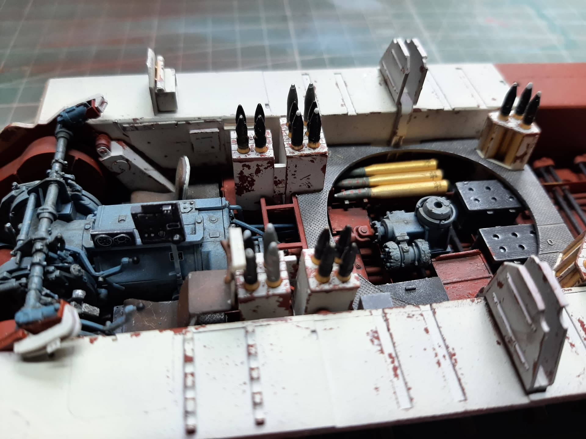
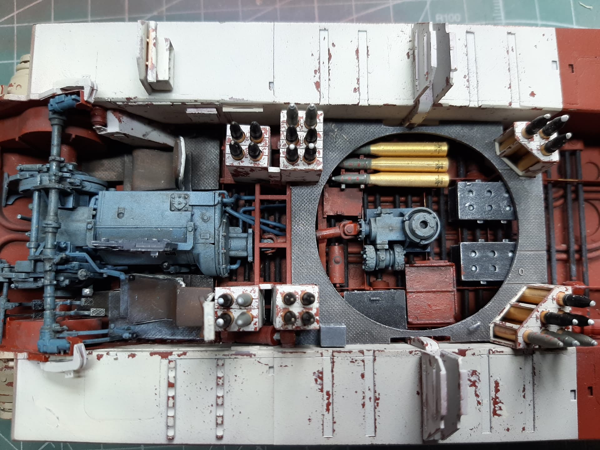
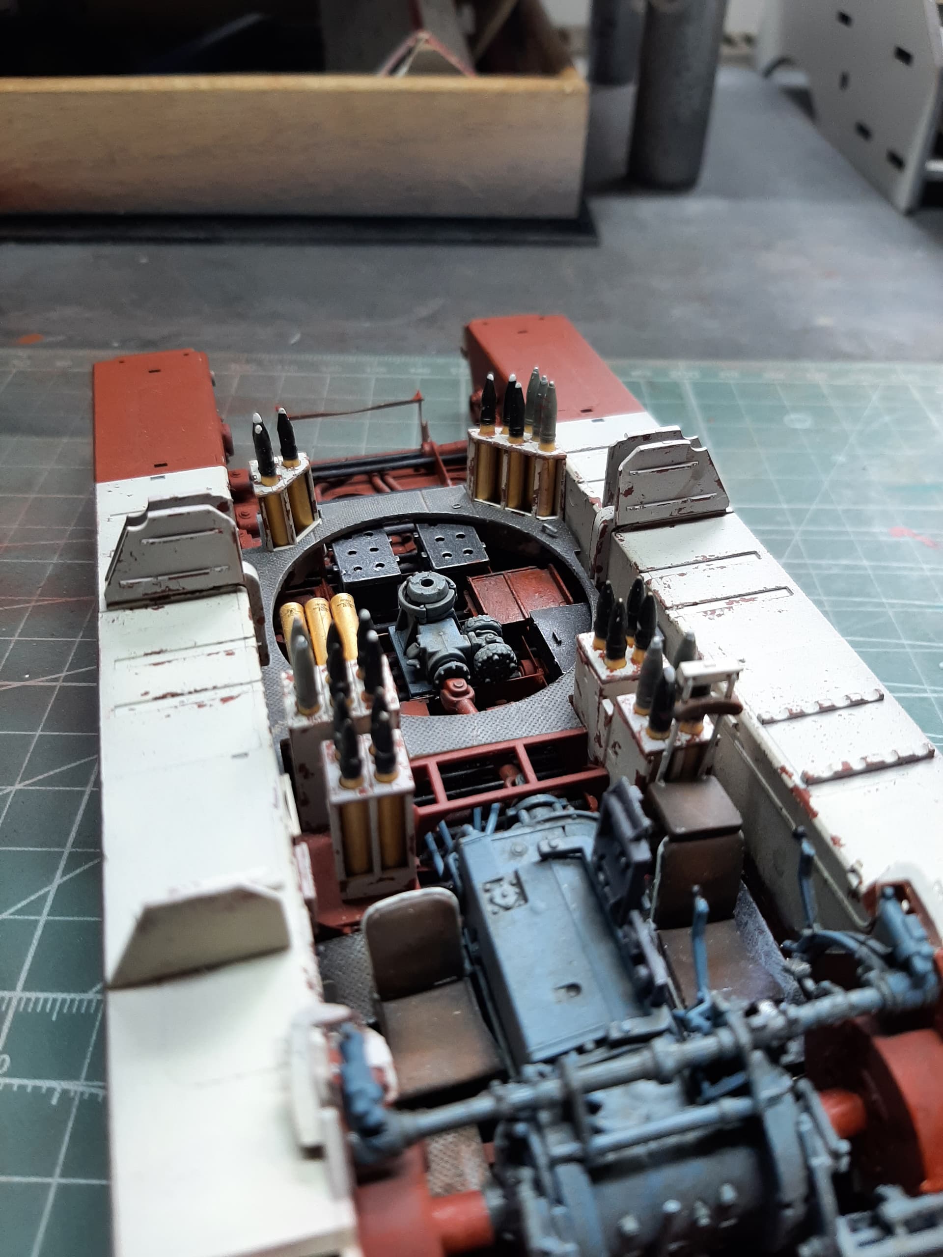
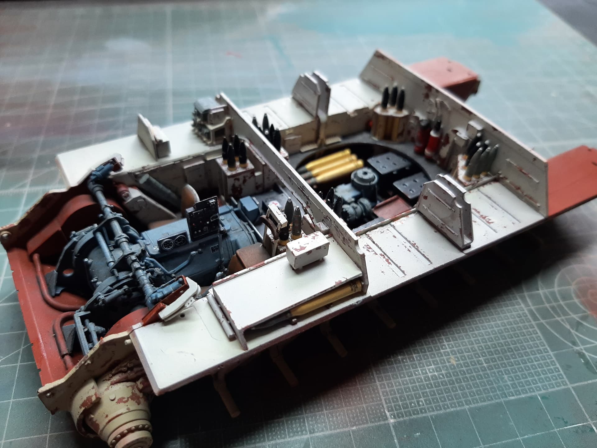
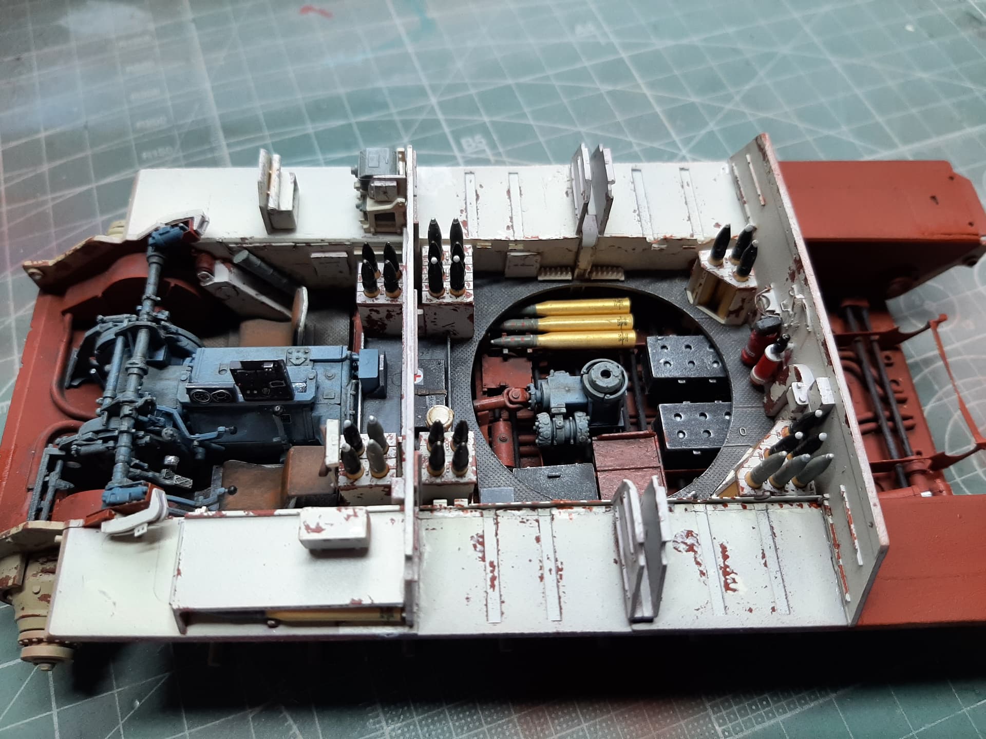
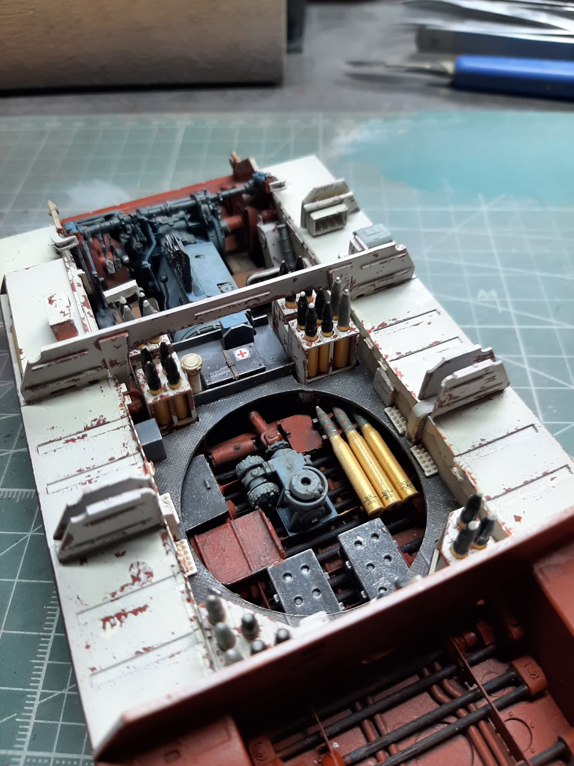
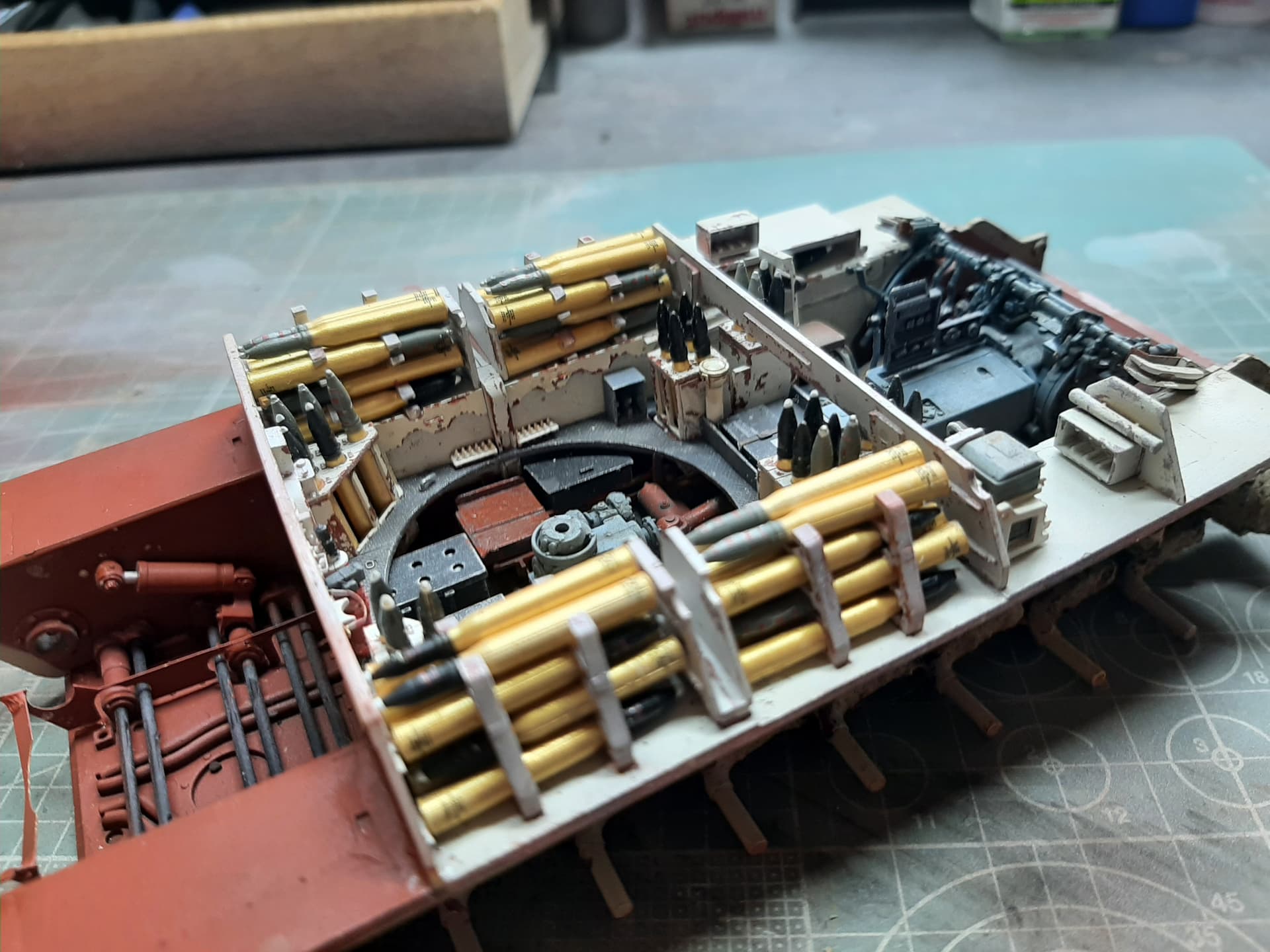
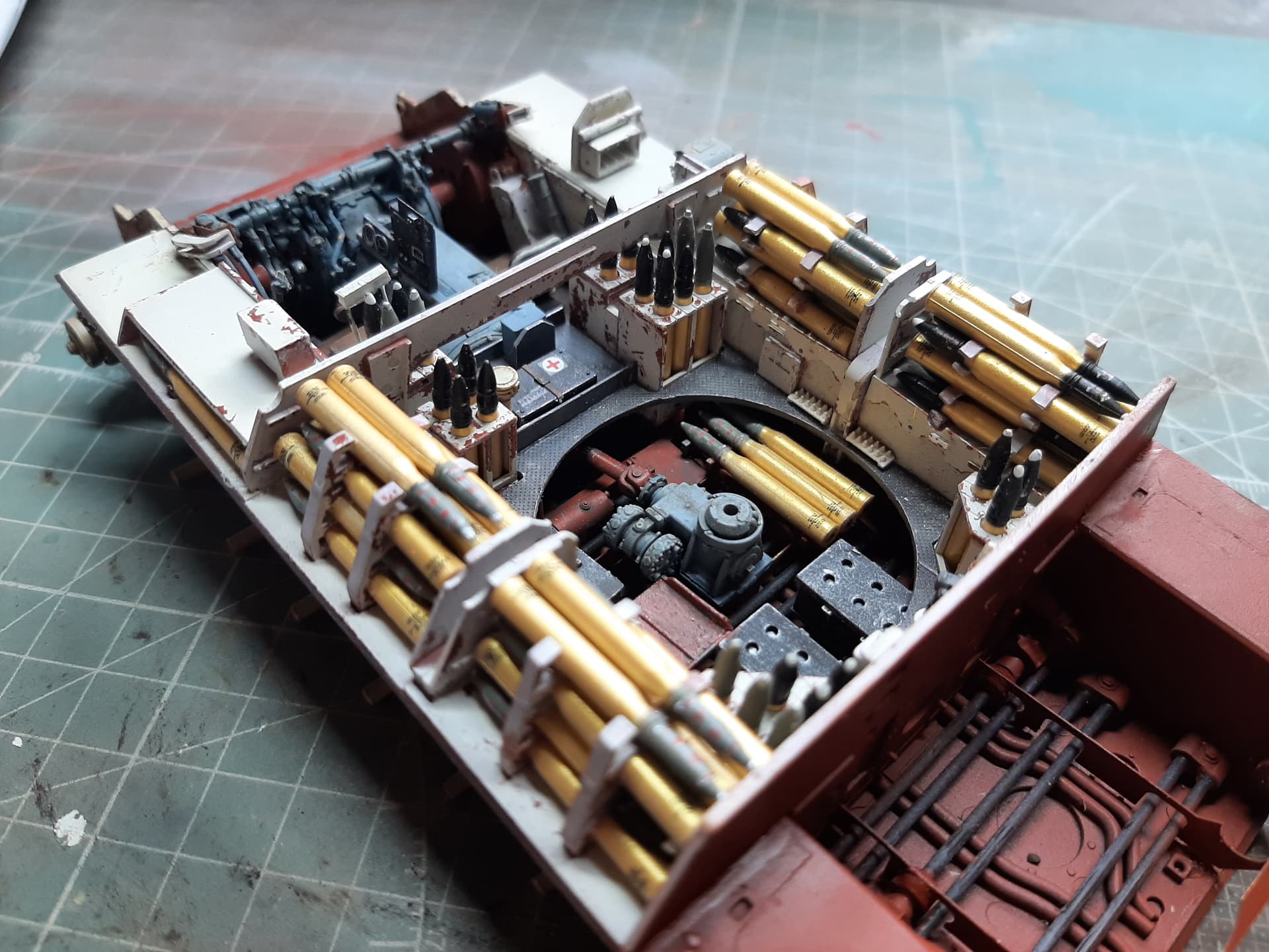
More of the interior detail has been completed. In fact, all that is left to do in the fighting compartment now is the sponson ammunition stowage (you can see where it will be, the grooves on the upper surface of the sponson floor).
Its been slow progress, and a lot of cutting, filing and sanding has been necessary in order to get things to fit. This all stems from way back when I very, very slightly mis-aligned the torsion bar assemblies. Beware, getting that bit right has proved to be the single most important aspect of this build. Also, the lower hull sides come as seperate pieces to the hull floor. If you glue this up wrong, even fractionally, then you will have a real job getting things like the engine firewall (amongst other things) to fit without filing because the now constructed hull tub just simply wont be wide enough.
However, i’m generally quite pleased with it. Made a schoolboy error when applying the decals to the first aid kit, as you can see, there is some silvering. Note to self, never forget the gloss varnish cote before application!
Whats next, well, i’m going to stop on the build now and concentrate on muddying up the hull sides and swing arms. not too much, but I feel it will benefit from some sympathetic weatherring.
Let me know what you think.

4 Likes
Very nice. I’m psyching myself up to tackle mine. I’ve also got the PzIV G/H. I understand there are some accuracy issues with the latter on the comms equipment, but I can live with that.
Some more progress, and the interior (fighting compartment) is very nearly complete.
I decided to build this with a full ammunition load-out. You might say that isn’t representative of a real vehicle, especially late war, but I don’t really care. This is more about display and interest for the observer than absolute accuracy.
So, there’s some touching up to do around the ammunition and bracketry and some MG ammunition sacks to hang on the side clips attached to the interior side-walls, but then it will be onto the engine compartment.

7 Likes
Still more great work Khouli. I am a bit behind you on the same kit. I have taken your warnings to heart regarding the difficulties related to the installation of the torsion bars and the PE cross bracing. I was very careful to do everything I could think of to try to avoid these issues. I tried to make sure that paint thickness and other non-obvious issues were considered as the hull sides were prepared as shown below.

After assembling the hull sides to the hull base I gave the unmodified torsion bars a try. Sure enough, there was a bow in each just as you - and others - have made note of. So the only thing to do was to sand the larger end of each piece until it fit.
Before I installed the torsion bars I worked on the PE cross bracing. I started out by bending the mounting tabs at the place indicated on each piece. I then did some test fitting.

After numerous attempts I could see that the cross bracing definitely wanted to bend to fit between the hull sides. I thought I could see that part of the problem was that the holes in the mounting tabs were two small to fit over the locating pins on the hull sides. So I opened up those holes.
After test fitting again the fit was better but there was still a little bending going on. I thought it was possible that once the longitudinal bracing was installed and the various intersections between the cross braces and the longitudinal bracing were fitted properly this now minor bending might be dealt with. So from here I left the cross bracing in place - but not glued in place. I then proceeded to attach all of the torsion bars. After the torsion bars were in place I then positioned the longitudinal bracing. As I had hoped this made it possible for the cross bracing to be properly positioned. I think this approach could be the way to solve one of these very troublesome “fit” problems.


I’m pretty happy with the results. “Fiddly” doesn’t begin to describe what’s involved here. Without the forewarning I’m not sure where I would have ended up on this build.
So I have two bits of advice: 1 - place the cross member into their approximate position unglued before installing the torsion bars and 2 - be very careful that there is enough room between the rear longitudinal bracing and the forward longitudinal bracing to allow for the later installation bulkhead separating the fighting compartment from the engine compartment.
Again, nice work Khouli and thanks for the guidance and examples.
2 Likes
Thanks friend, i’m glad I can have been of help, even if it was to demonstrate to you ‘how NOT to do it!’.
All in all, your progress has made much better (neater) than mine did and with hindsight, I would have built the hull bottom just as you have done - but, I was going from scratch and it was trial and error. I did indeed have to cut out slots in the rear engine firewall/bulkhead to get it to fit between the PE longitudinal hull spars. However, when assembled, and with the engine in place, it will not be visible. In fact, hardly any of the detail below the fighting compartment floor level is visible after construction, as it is covered with fittings and tread plates. Still, we know its there. You will also notice a very slight ‘bow’ in my engine firewall/bulkhead - but at this point, i’d got fed up with filing the sides down in order to make it fit.
Next up for me, the engine compartment.
Better late than never this just popped up on my radar for the first time - Exceptional with a capital F, I particularly like your colour sense for the interior, it just looks so right. Beautifully built despite the issues too 
Looks great!
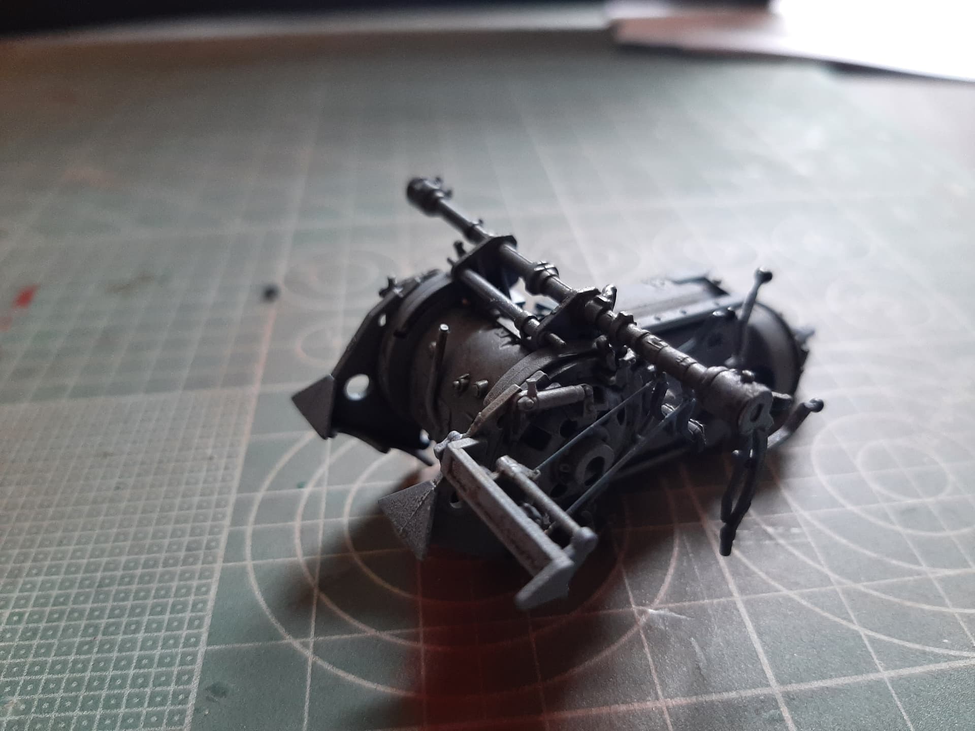
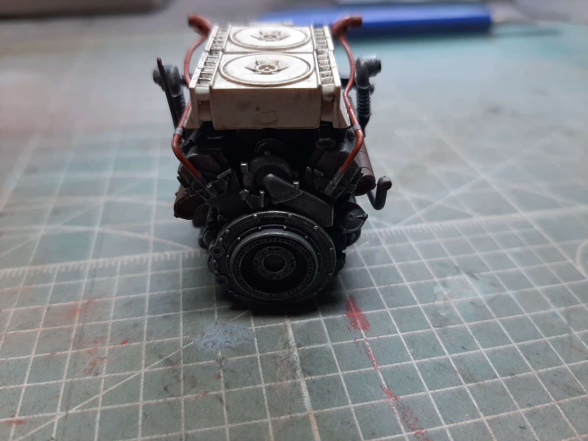
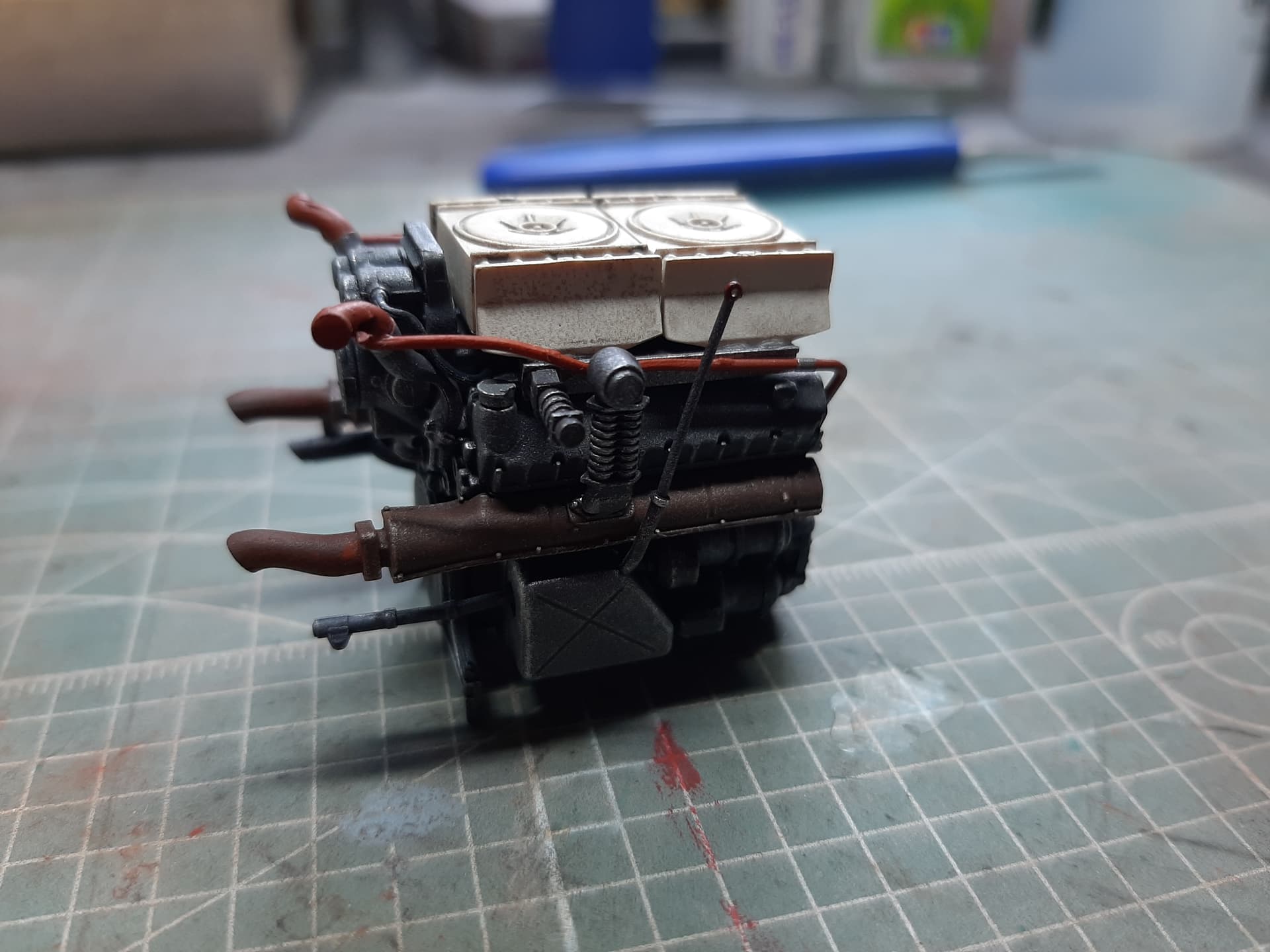
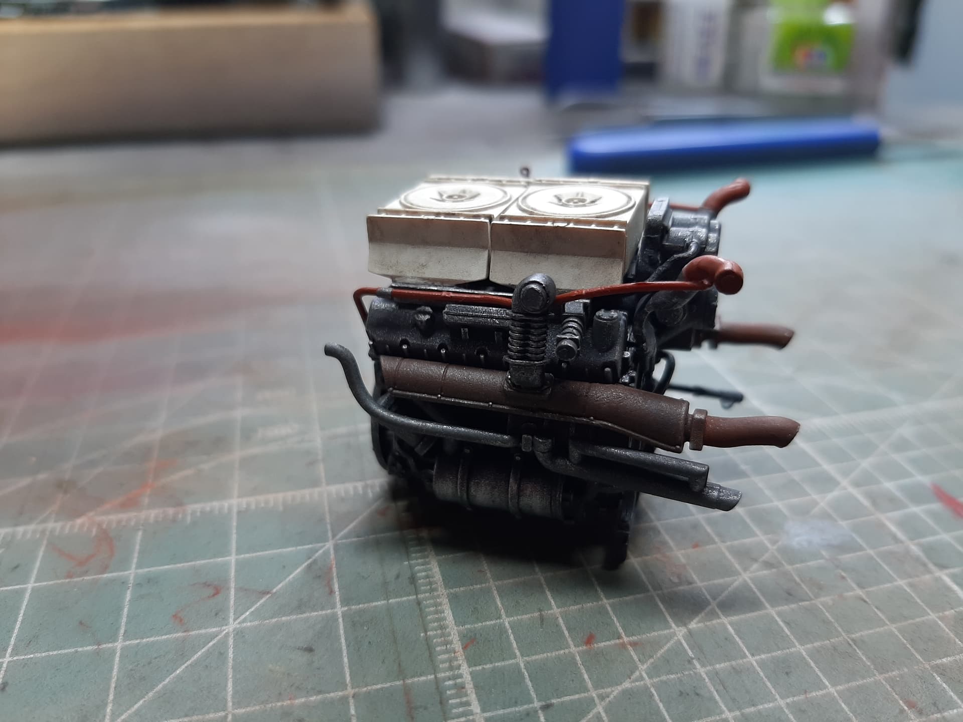
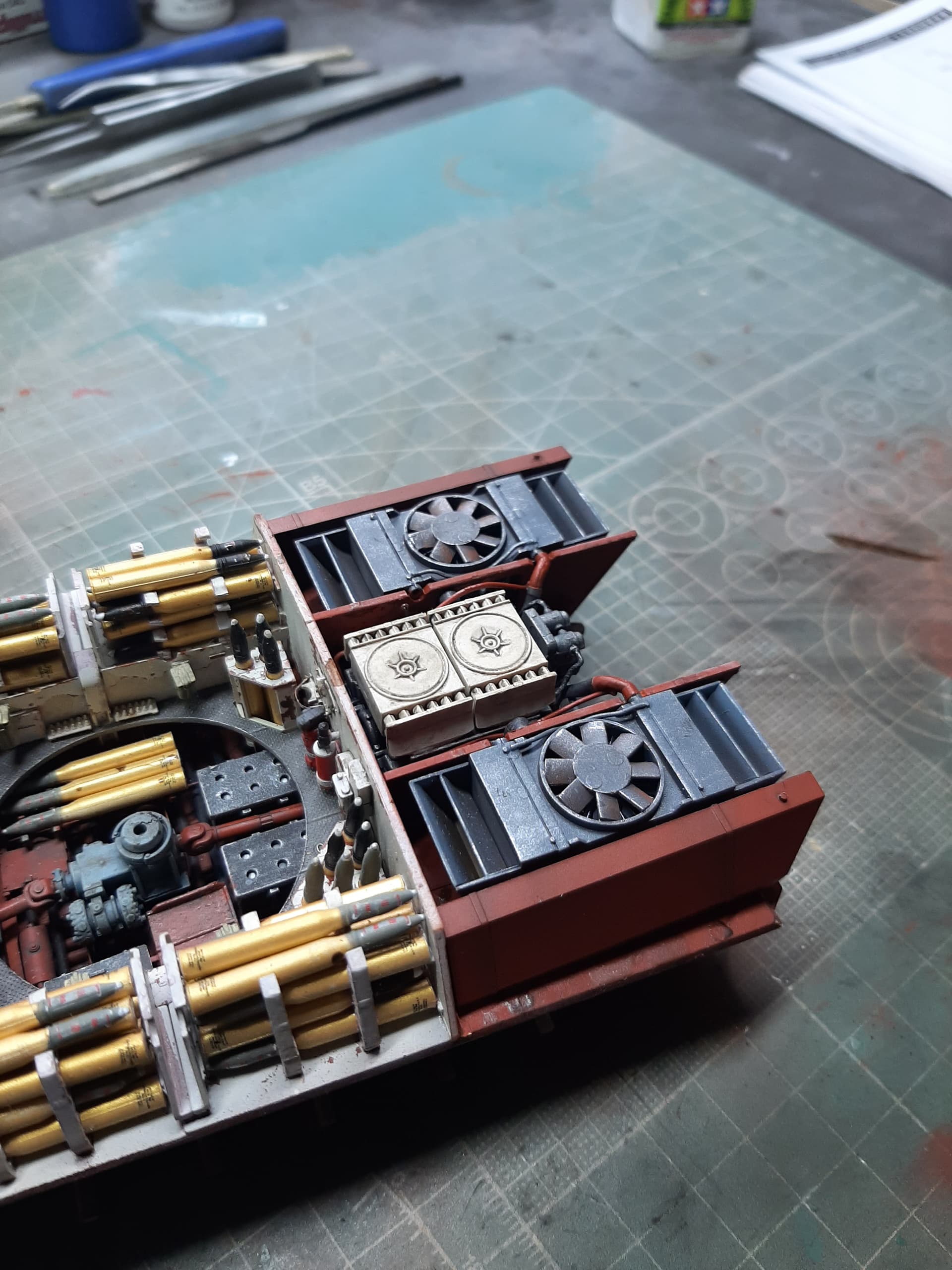
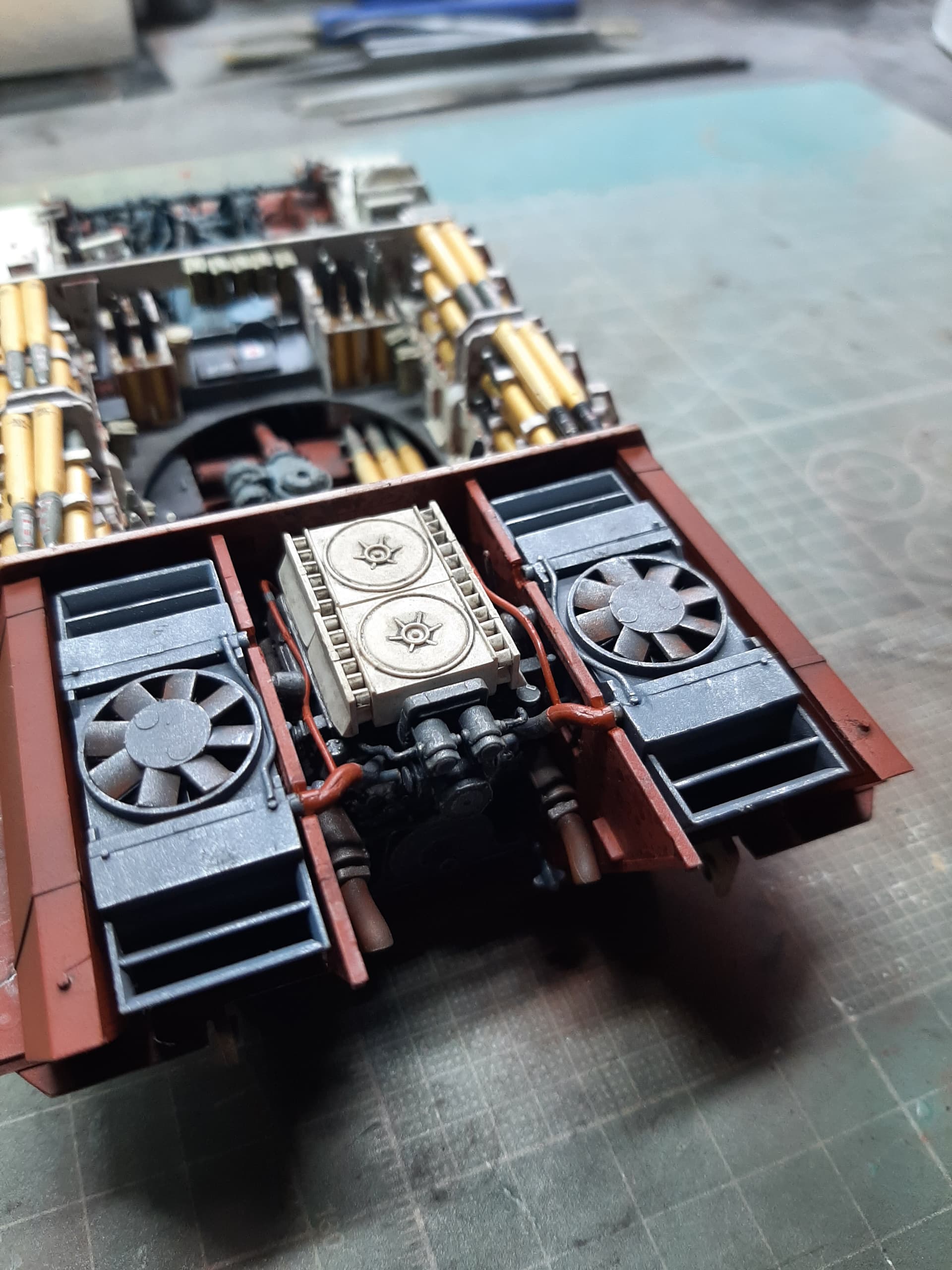
So, I have been working on, and have now completed construction of the Maybach HL 230 power pack.
This is a kit within the kit - I did count and +/- one part maybe, there are 69 individual parts that go into building the engine up. Some of the parts are really small, and it isn’t always obvious from the instructions how some of the pipework is supposed to plumb in…
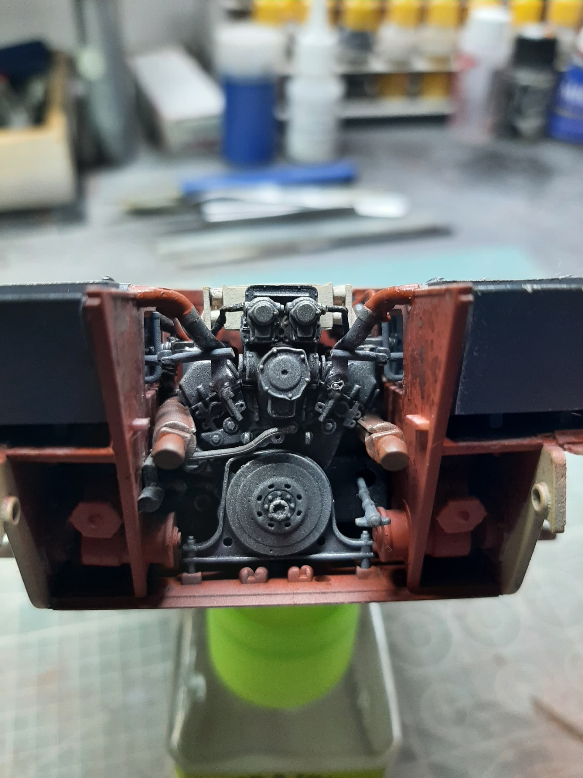
If you’re building this kit yourself (and I know some of you are) BE VERY CAREFUL WITH THE CARPET MONSTER during the construction because there are number of small parts. Also take care when removing the hoses from the trees, they are fragile, but a sharp X-Acto knife will make it easier to remove. All of the parts went together well and no putty was needed because all of the seams were in natural places and/or not noticeable. A couple of notes I managed to find out during construction. In step 55, attach the completed muffler (J48, K64, K65) before you attach parts J50, J85 and J74 to prevent breaking the dip stick. Also, in this step, leave off the hose, part K30, until Step 58. That way it will align better with part J73 in Step 58. In Step 59, make sure the locating tabs on the completed air filters are pointing in the same direction when attached to K69 and K70 - that way they lock down to K31. Also make sure K69 and K70 are in the right direction as compared to the top of the engine and part K31. The instructions also have you attaching the stub pipes that come off the side of the engine after installing it in the hull - no way, that would be far too tight and fiddly, i’ve attached them early, reasoning that they pretty much sit within the engine’s envelope and wont impede the engine’s installation.Other than small pieces that can be easily lost, the engine construction went without any problems.
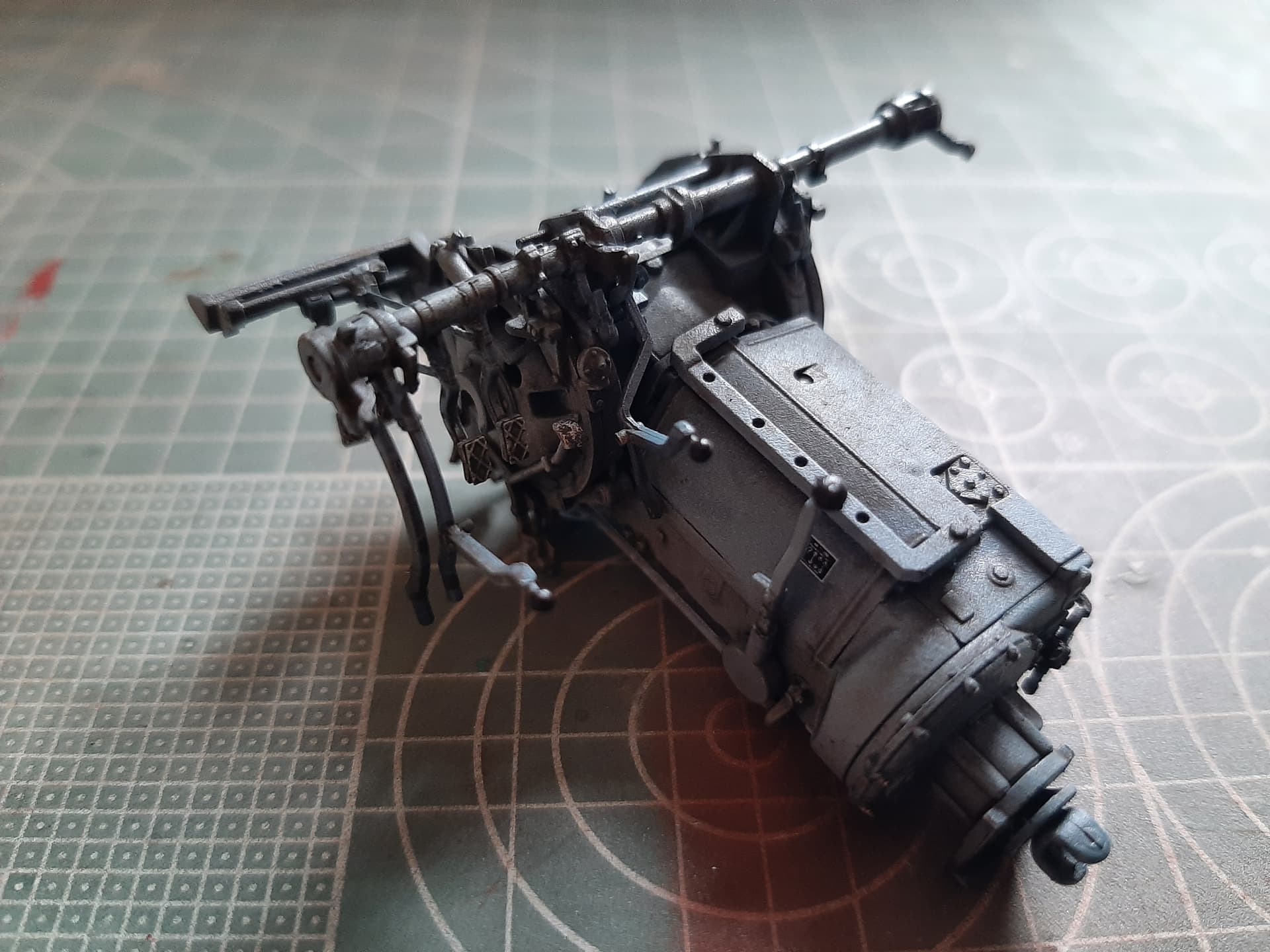
I wasn’t sure about the paint job, but opted for a base coat of (all Mig) Satin Black, then a ghost over of Dark Tracks, then Field Grey and finally RLM 66 Schwartzgrau. Highlighted with some Hannants Oily Steel. Exhausts were the same really, but majored on the Dark Tracks and used some Vallejo rust pigments to accentuate the mufflers and exhaust pipe.
Not going to bother weathering this up, all you can really see when the engine is installed are the air filters.


8 Likes
Very nicely done. As you said, a model within a model … and perfect for a little maintenance Dio with the pack being removed or at least prepped for it with the engine decks off … you have done a lovely finish on it as well with the painting and ageing 
1 Like
That engine is a thing of beauty! I love the finish. Excellent color choices and a perfect build.
69 parts? That’s enough for two AMT car kits! Maybe three!
Why thankyou gentlemen, it is very nice to have such praise. You know, I was looking at it yesterday thinking i hadn’t done that good a job on it, so it seems i’m in a minority.
Khouli, make sure you keep the photos, then you’ll have a record of the engine! That’s all I have to show for the Takom King Tiger and now the RFM Panzer IV!
Nice work Khouli! I particularly appreciate the step-by-step advice regarding the assembly as I am about a transmission/final drive build behind you. And I agree with Hohenstaufen regarding the regrettably lost detail after these nicely made engines are dropped into the engine bay, never to be seen again. The backdrop for these full interior kits should be a photo montage entitled “What You Can’t See”.
Thanks, appreciate the praise.
Every picture seen in this blog has been kept in a folder on my computer, and i’ll probably keep them. Not sure why, I probably won’t build another Panther for ages, let alone one with interior detail.
@RAK If ever you want to PM me regarding finer points of this build, feel free to do so, it may help you avoid some of the pitfalls I have come across.
I’m working on the cooling fan assemblies now, will keep you up to date.
Okay, first, a word of warning @RAK
DO NOT attach the stub pipes before installing the engine as I did. The instructions called out for these to be fitted after engine installation and for once, the instructions were correct. The engine will not fit into the engine compartment if these pipes are attached. Luckily, I don’t use much glue on styrene parts and I was able to relatively easily prise them off the engine and re-attach them after the engine was installed. Seriously, the engine is a really, really tight fit. It makes me wonder how mechanics ever worked on the engine without lifting it.

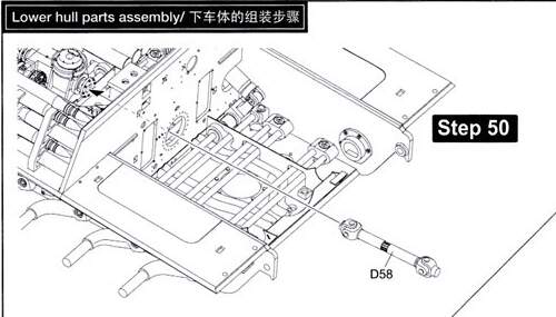
Also, jumping back a bit, do not attach drive shaft, Part D58 until the engine is installed.
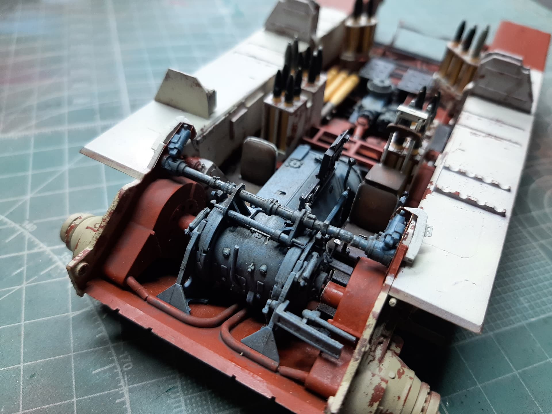
Now the engine is in place, the drive shaft is connected, the air intake fan assemblies are in and so are the fuel tanks. There is still some plumbing to do at the rear of the engine before the fuel & coolant header tank assembly goes in. But overall, it went quite well and i’m fairly pleased with the results.

4 Likes