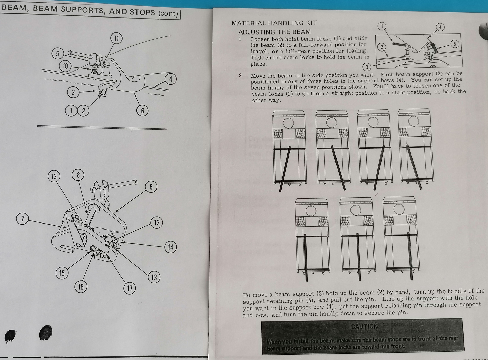
Would this answer some of your questions? The two beam support bows are bolted onto the cargo bay side walls, whereas the other bows are only slid into holes.
2 Likes
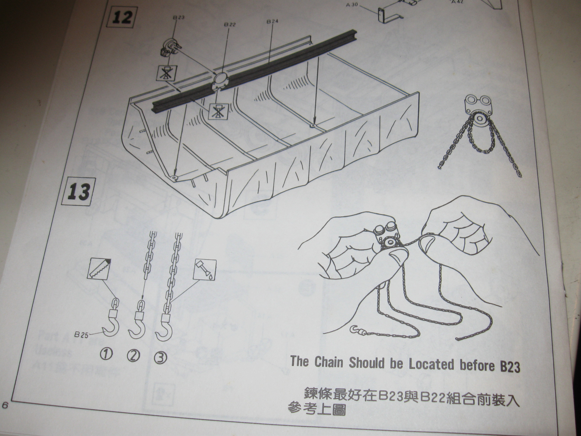
Thanks, those explain much. It’s too bad they went with the simple plan instead of offering a way to show it without the tarp and interior bed details. Oh well, can’t have it all.  Wayne
2 Likes
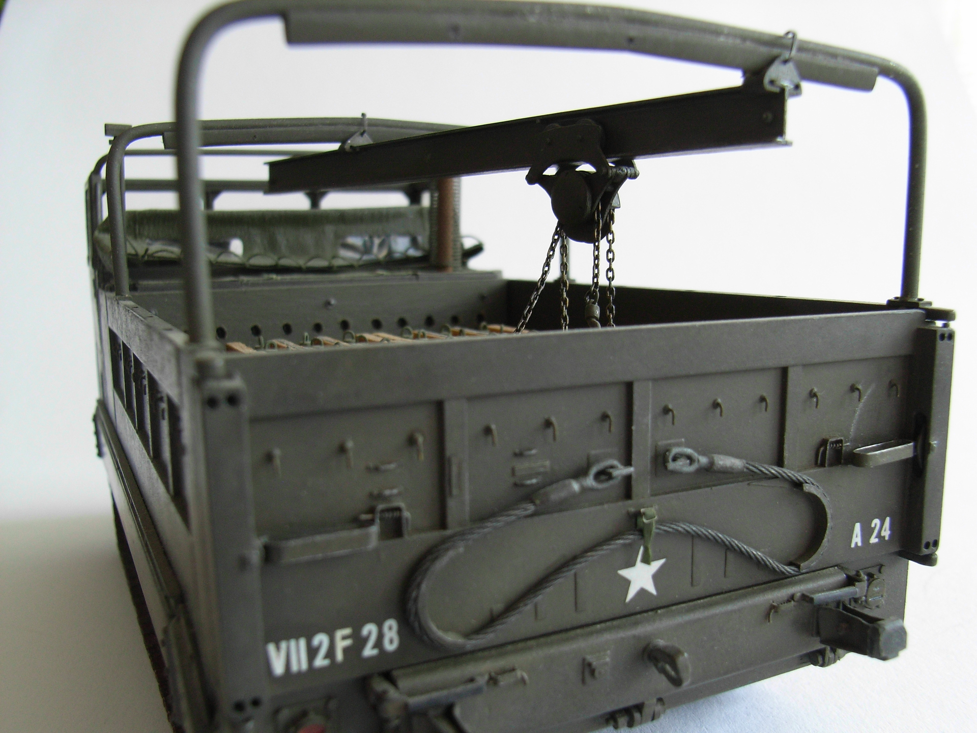
Some more information: On the move, the beam is moved all the way forward above the engine deck through the two-part tarpaulin front - the kit doesn’t even give a separation line on its front. And the holes in the beam-carrying bows are in a tapered brace on its underside, 2mm high on my model:
7 Likes


H.P.
3 Likes
Nice job on those tie downs.
1 Like
Thank you - that’s 0.3mm brass wire, and 56 of 'em all around the model …
3 Likes
Sliced Evergreen rod for the base?
1 Like
No, I wasn’t THAT mad - for all I remember, I just drilled into what was left after I removed what AFV had molded on as tiedowns. However, I’m not sure what exactly was there: we’re talking 1996!
1 Like
Really nice, do you have any more pics? I see you buolt it with the open cab, which I am interested in also. Wayne
1 Like
More good pics, thanks Frenchy. Wayne
1 Like
Interesting load configuration that. It looks like it’s all just been piled up on the bed to be taken somewhere.
1 Like
For starters, look here:
1 Like
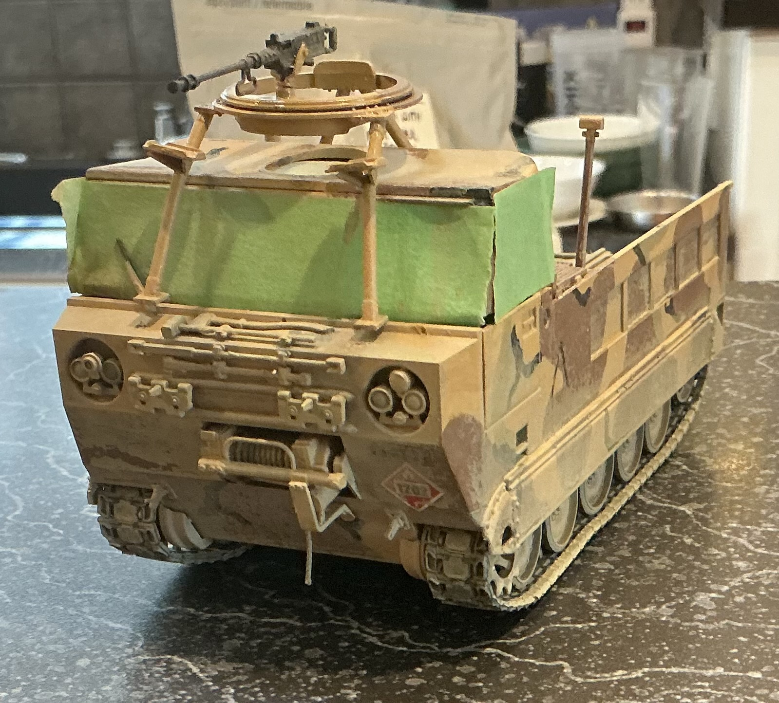
Some progress, weathering except for the windshield, Hazmat diamonds and bumper codes partially obscured by the weathering. Will prep the windshield and start finishing the details on the carrier and the pump deck this weekend.

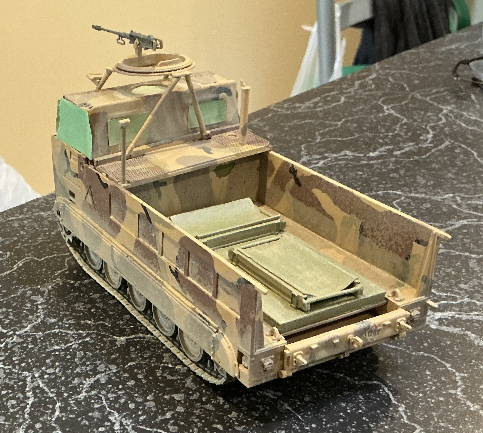
3 Likes
Cab now cemented in place. Fitted the tools and weathered the windshield.
Scratchbuilt 2 replacement wipers and put the gun ring in place.
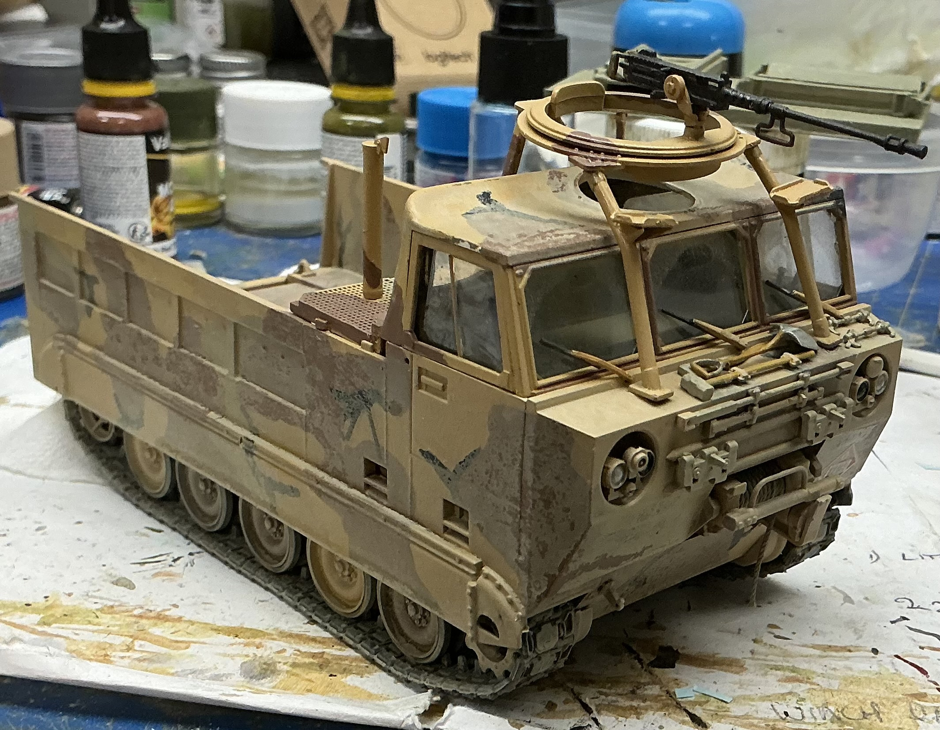
Hopefully on to the pump deck and fittings tomorrow.
9 Likes
Nearing completion on this M548. Should complete things on the weekend, then on to the next project.
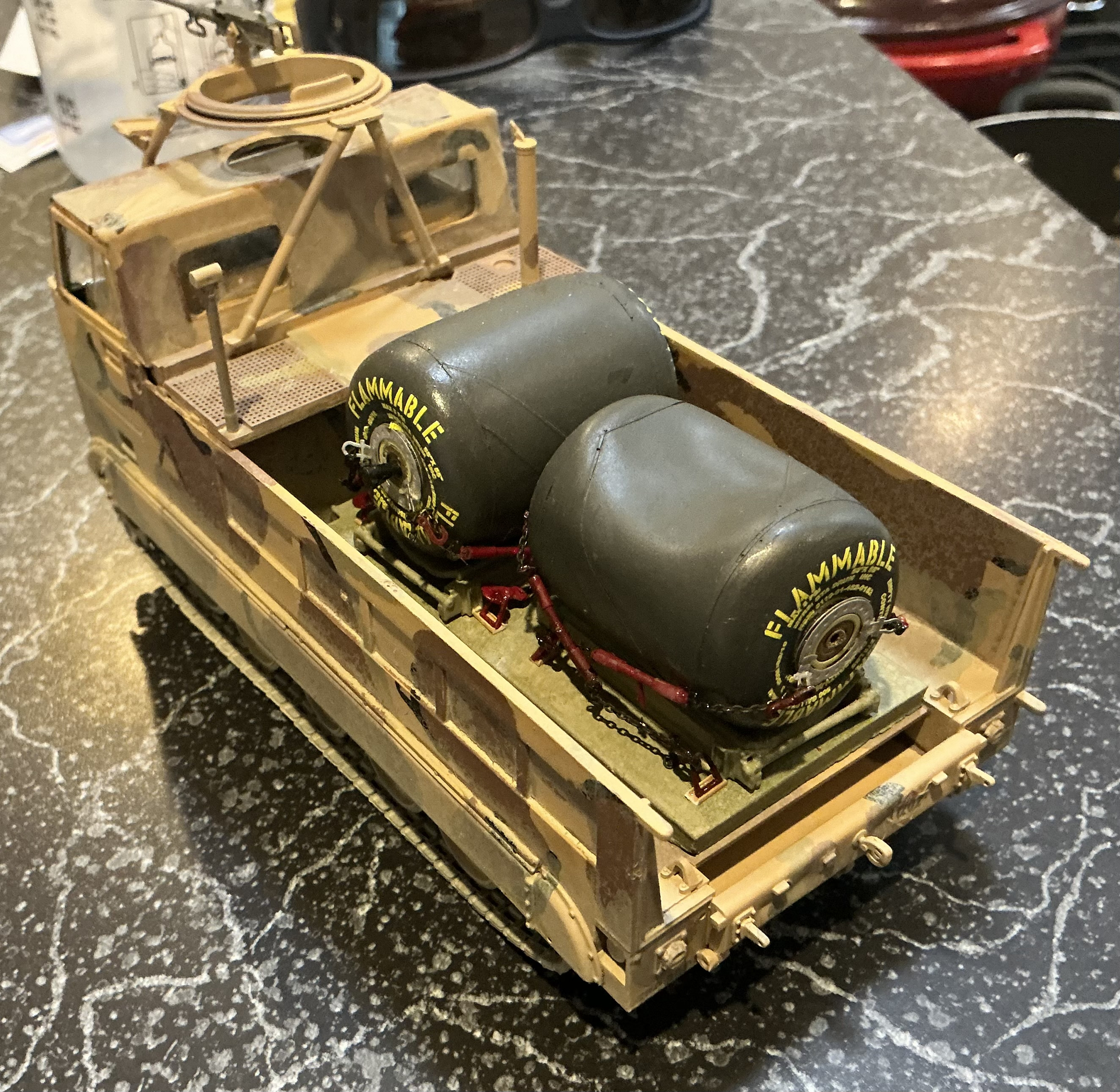
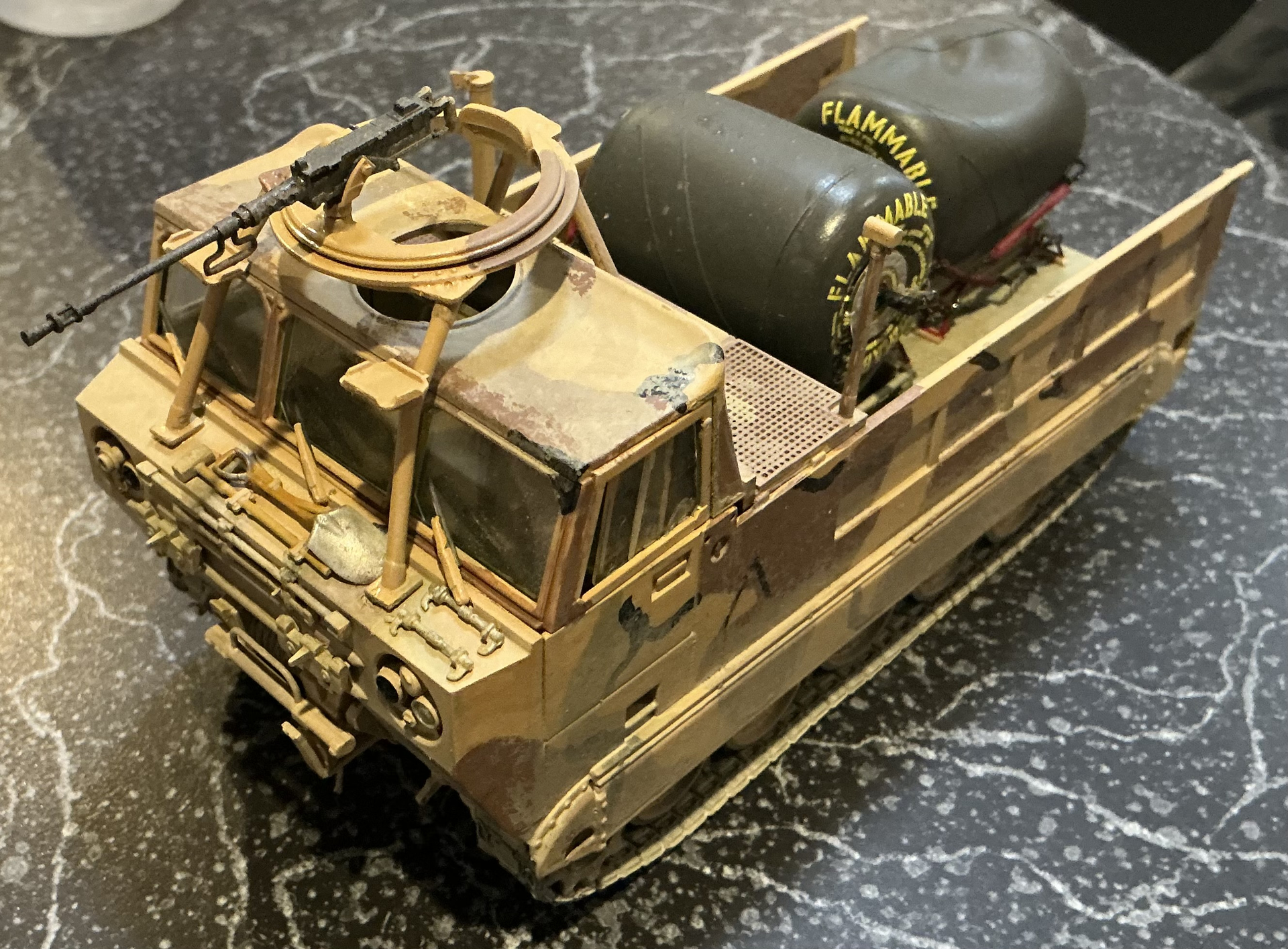
10 Likes
Didn’t quite finish today, but the hoses, pump and hose reels are in place.
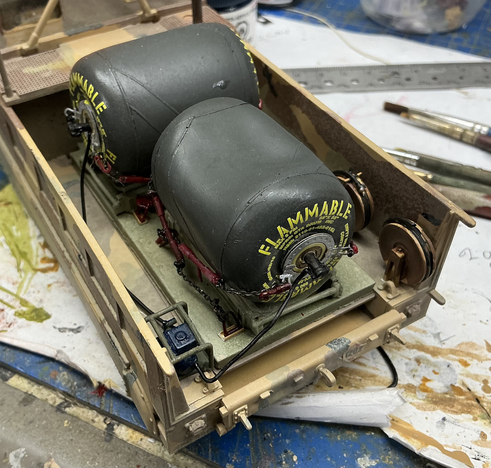
A little paint on the hose reels, some Vallejo Matt in places, then she’s done.
5 Likes
Looking good. I think you might need to look at the hose routing though. I would think the two hoses from the bladders would come together into a “T” and then into one side of the pump. The hose coming out of the pump should go the hose reels. Or maybe two pumps with one for each bladder and a separate hose reel for each.
1 Like
Thanks Gino, I’ll get into that tomorrow.
Appreciate your advice.
D
2 Likes
This is something I have a little experience with, having worked in an oil refinery before I joined the army. Plus my huge perpetual diorama I’m working on as a FARP on it, which is why I cast all those bladders to begin with. You can’t have two bladders tying into a T without running into difficulty, namely, cross-contamination of fuel with one bladder, has water or impurities in it. The other problem has to do with suction. I don’t know what’s going on with your vehicle and haven’t looked at the pictures very closely, but normally both bladders would feed into a manifold, each with shut off valves. That manifold would feed into the pump and then the pump would feed the two hose reels so that you could theoretically fuel two vehicles at one time
3 Likes
Thanks 18 Bravo, great information. Do you have any pics so I can this right?
If no pics, maybe you could pm me a sketch?
3 Likes