Thank you, Richard! Much appreciated.
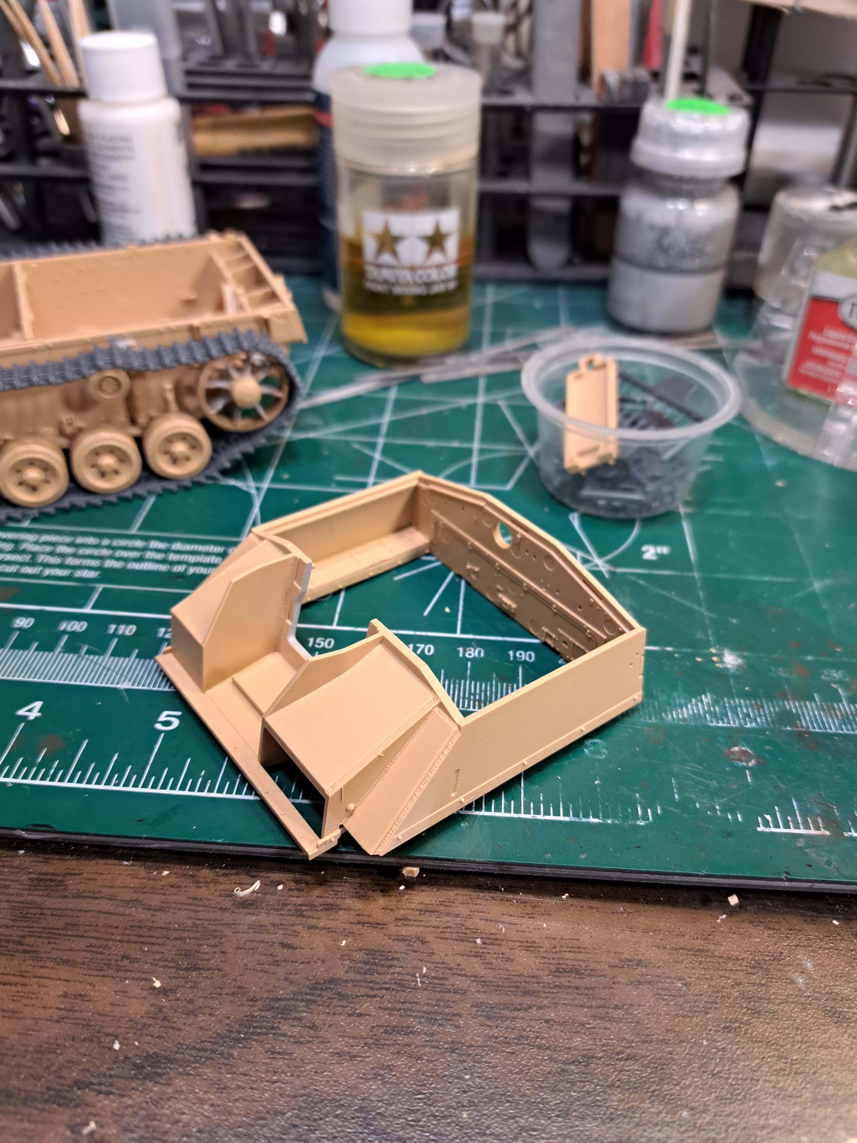
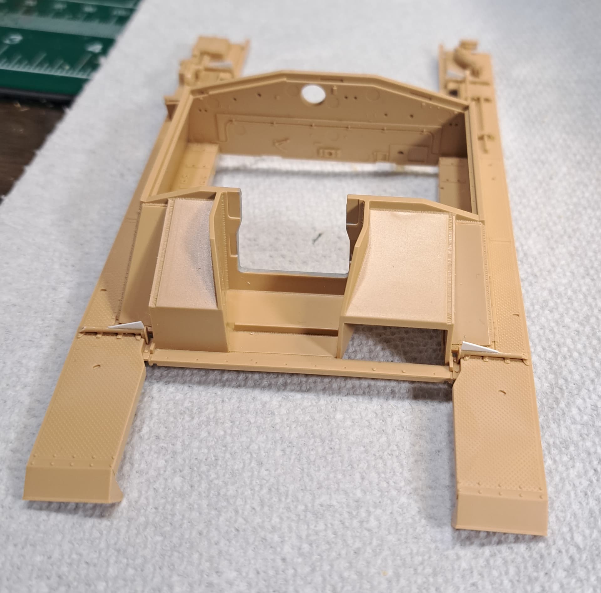
Upper Hull Superstructure
Steps 9 & 10 plus sub assemblies A3 & A4, clean up easily with no surprises. I was pleasantly surprised J17 & J18 test fit near perfect.
Thank you, Richard! Much appreciated.
Upper Hull Superstructure
Steps 9 & 10 plus sub assemblies A3 & A4, clean up easily with no surprises. I was pleasantly surprised J17 & J18 test fit near perfect.
You’re knocking this out!
I’ve got one in my pile of shame and now you’ve got me looking at it again.
I’m getting ready to write a page about radios in Stugs and how no existing kit has a likely configuration there.
Do you want to hear how RFM’s kit rates in that area?
David
Wow, that one link made a massive difference Wade, the sag looks great now ![]()
That’s da ticket!
I for one would be very interested David, I’m sure most people would. It’s not something most modelers pay attention too because it’s inside the vehicle obviously and not many guys do interiors.
OK, here goes.
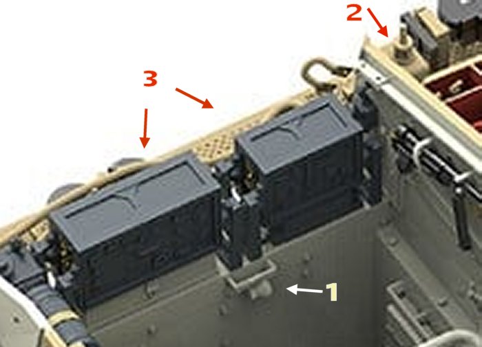
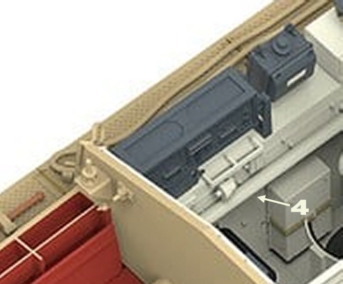
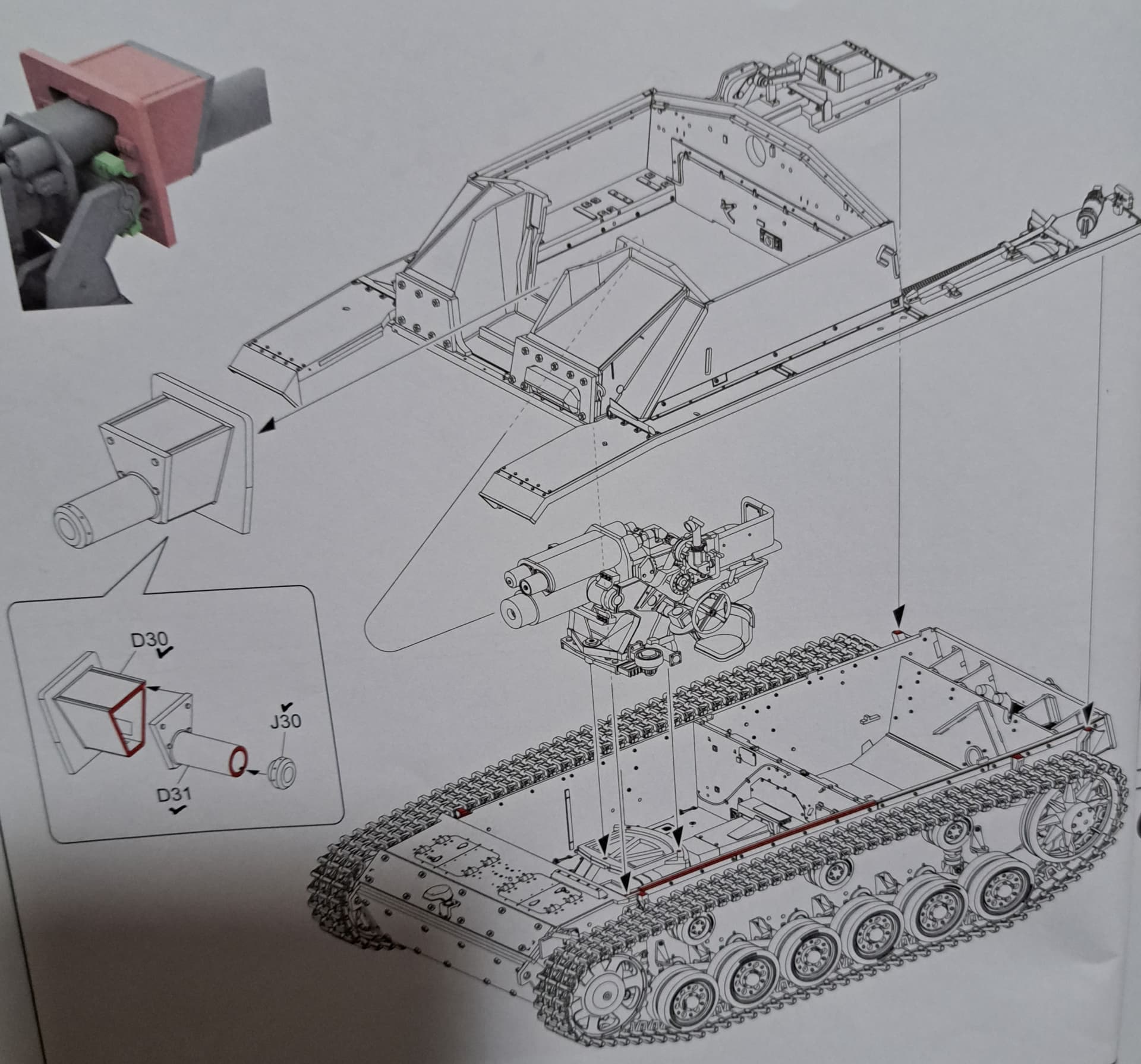
RFM have four mistakes in their model (if these photos are the correct ones).
The connector socket that they put here, under the protective rail, is a post-war Finnish modification seen in a Finnish museum example. When the vehicle was in German service, there was a rectangular box here.
This model has been equipped with the FuG.8 radio. That radio requires the “star” antenna and a special armoured base socket for it, which contains the ceramic insulator. But the model provides the ordinary antenna base instead.
The FuG.8 radio itself. While it’s a valid and correct radio to install here, it would be used only by the overall lead vehicle of a unit. I don’t expect that the decals in the kit all represent lead vehicles. Could you tell me?
Fixing error 3 would cancel error 2.
David
@DByrden David, please share with us any and all of your insights into the RFM Stug kit! Thank you!
I’m leaning towards buttoned up for this one given it only has the most rudimentary interior elements but I think some of the folks reading the thread on considering building the RFM kit with interior.
That’s fantastic information! A++
@Johnnych01 John, thank you. I was very surprised too thinking the track run would definitely need two links. With two links, tracks would have been so loose the Stug threw them on the work bench!
@Dan Dan, hope to get a couple of builds cranked out in cold the weather. Then focus on painting & weathering the new builds plus my fat stack of shelf queens.
The Fat Stack of Shelf Queens ![]()
3 Panzer IV’s
2 Panthers
2 Panzer III’s
T55
Been lurking for a while. Nice progress. Waiting for the finish and paint. ![]()
![]()
Thank you DV.
I’m looking forward to getting to paint again too! I probably need to review Stug III G introduction dates so see what flavor of dark yellow RAL 7028 is in the ball park.
Smooth? LOL! Not today
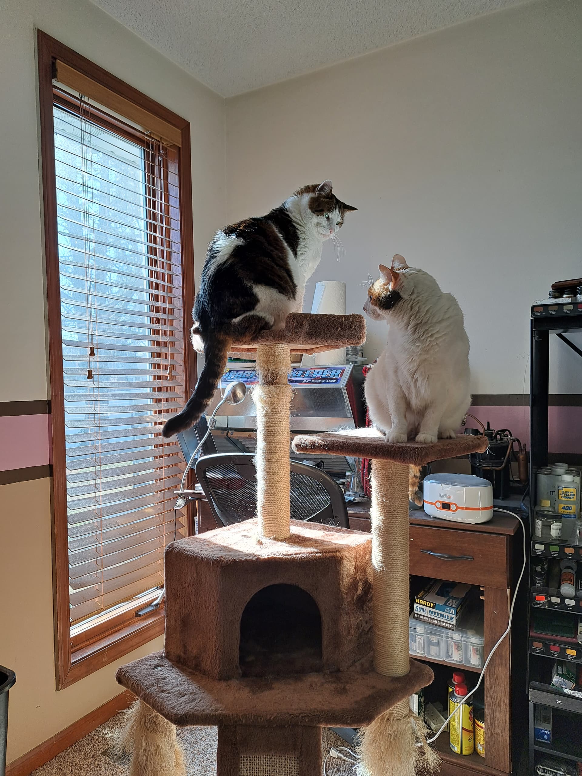
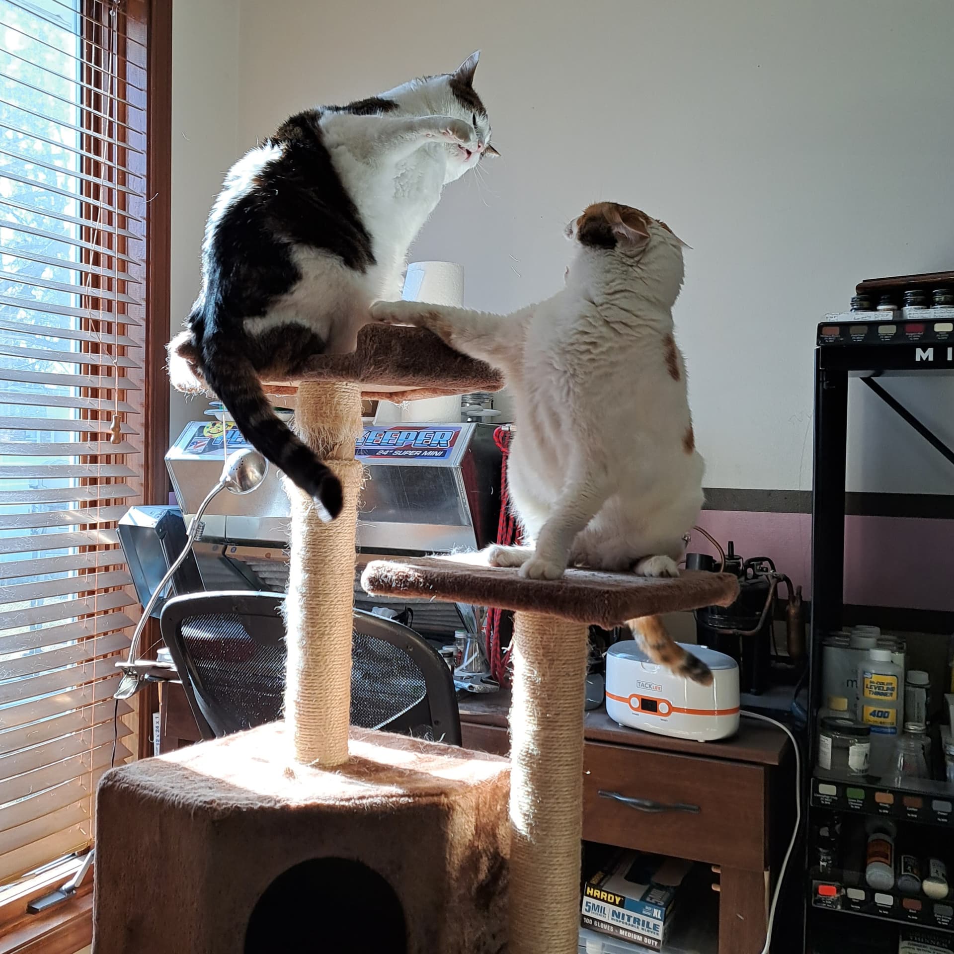
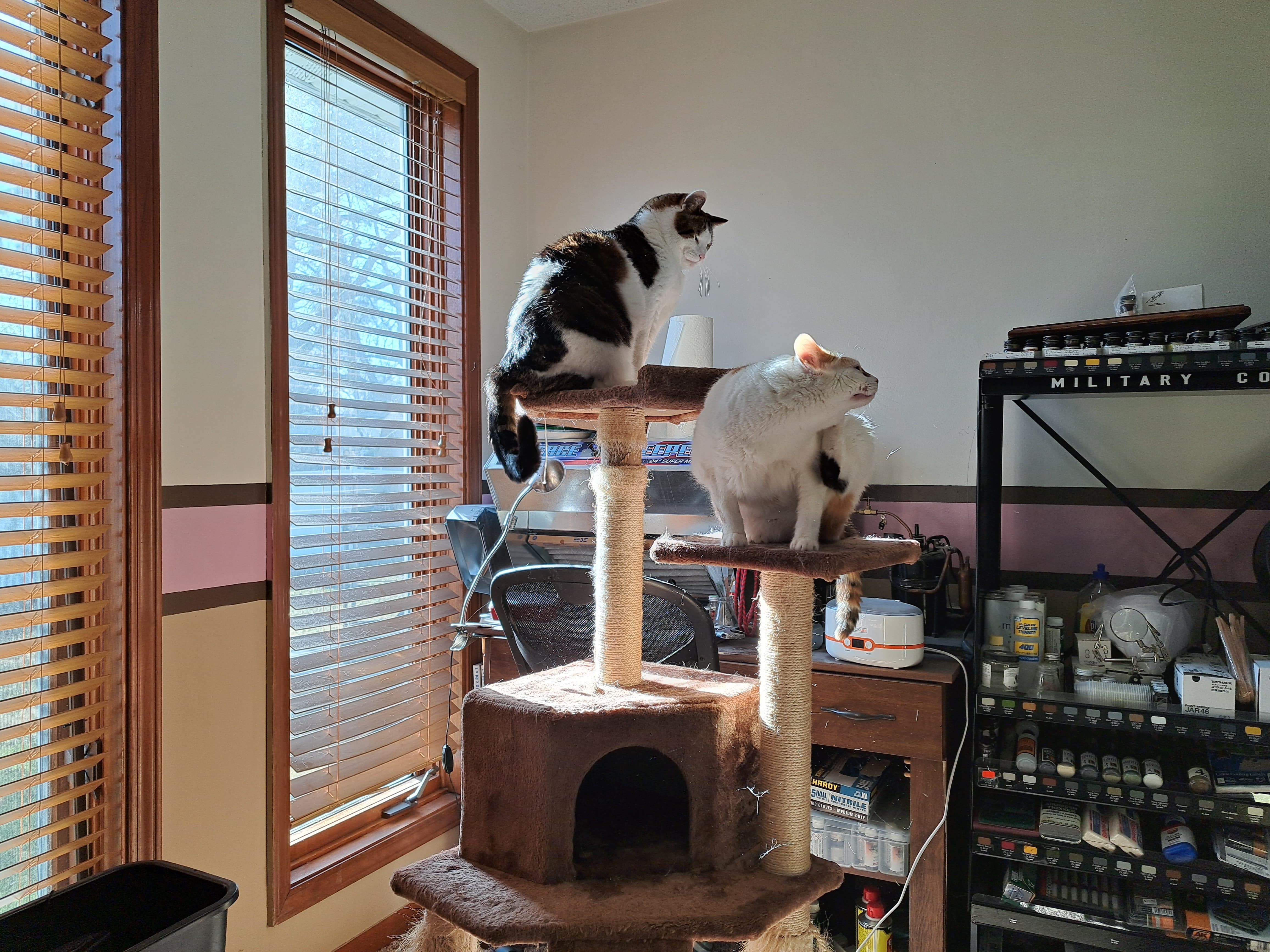
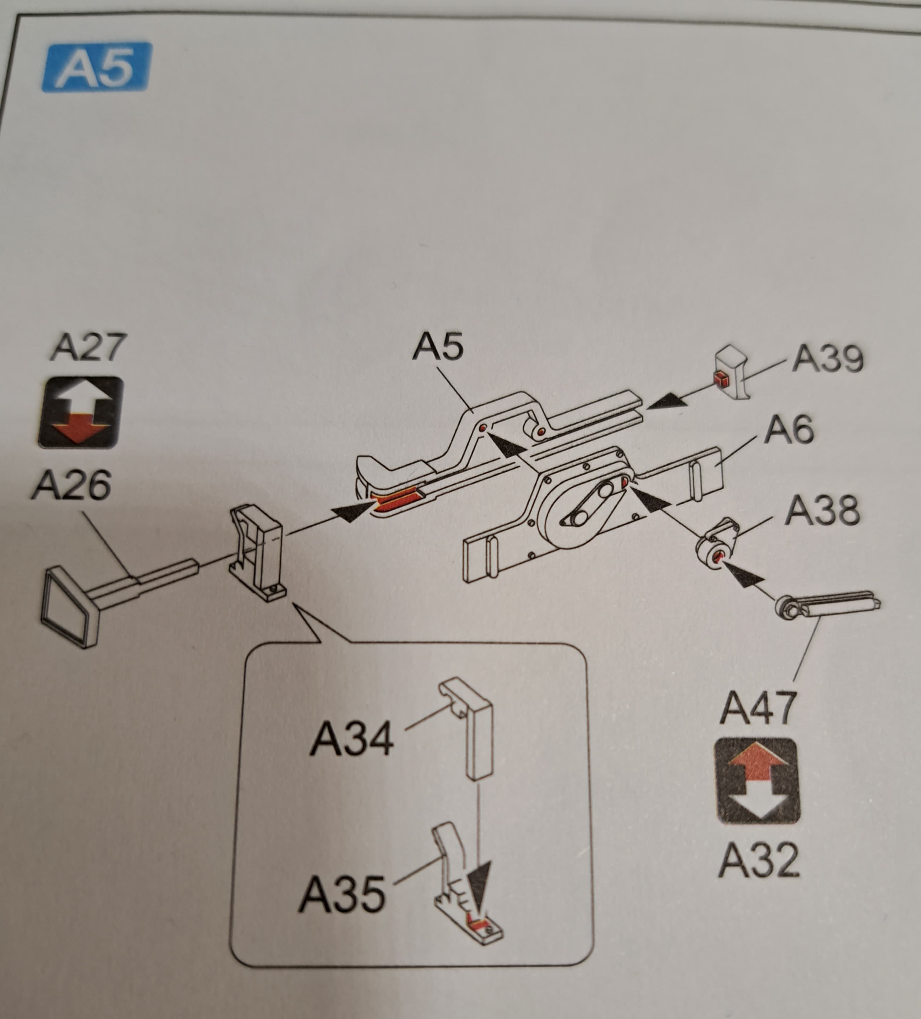
Sub assembly A5 aka The Jack just about got my goat to today. We had lots of drama in the hobby room. Kali (female, 12 pounds, white & tan) told Joey (tomcat, 17 pounds, tricolor) to get off of her cat tree.
He said make me, king of the jungle (house) babe!
She said definitely will make you…
…and she did make him. He sat in the door way mad…
So mid drama, A38 tweezer launches…I recover easily as it landed on my hand…lol
…then tweezer launch A38 into oblivion on 2nd attempt to pick up part…finally decided its futile looking for part A38 and decide only way forward is replacing. Zero luck with spares. Will have to make an A38 an “ERSATZ” part…the irony…wink
Finishing the ersatz A38…and then promptly tweezer launch it somewhere between Timbuktu and Siberia.
Ersatz A38#2 was made without use of tweezers. Moral of the story…don’t crutch on the cheapo tweezers like I did get the good surgical quality ones out even for the simple stuff.
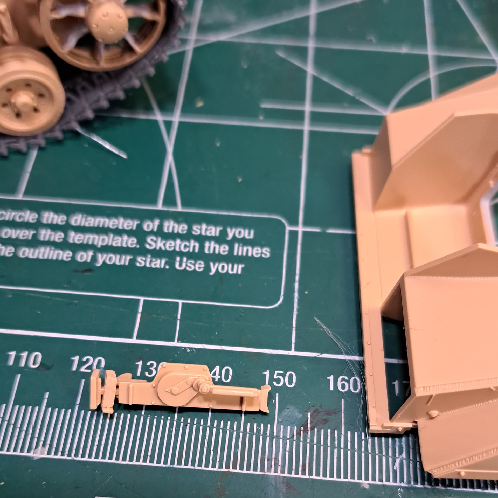
A5 The Jack w/Ersatz A38#2
The jack builds nicely. However, A5 &A6 did have the heaviest mold seams and required fair amout of clean up. Most I’ve seen in my copy of the kit.
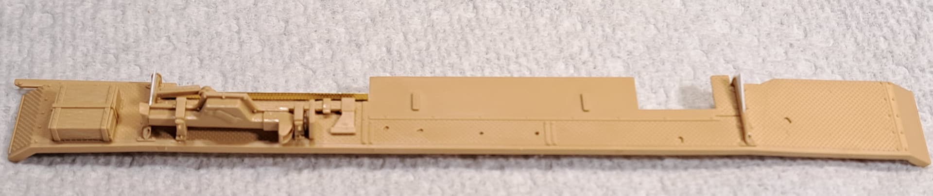
Step 11 Fender
Straight forward step with fair amout of parts clean up for fendwrs various attachment points and underside punch markers.
Four PE parts numbered Y3 caught my attention. It’s a thin small triangle shaped part that goes on top of a fender support. Decided to replace Y3’s with thin plastic card. Pretty sure handling fenders I’d break off the fragile PE parts super glued to the fender supports.
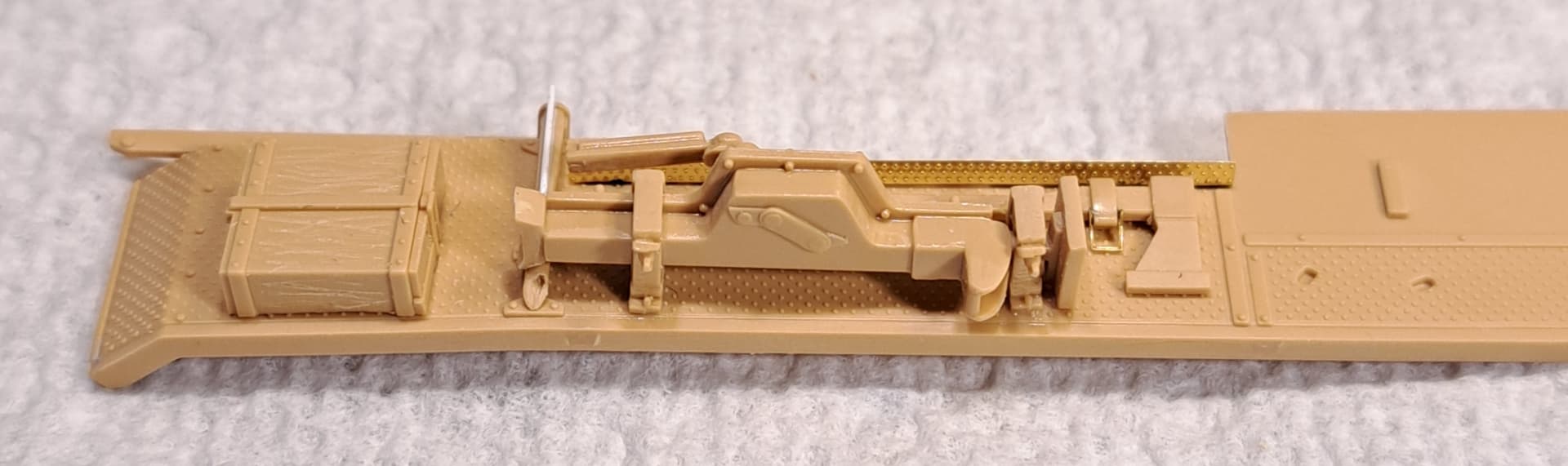
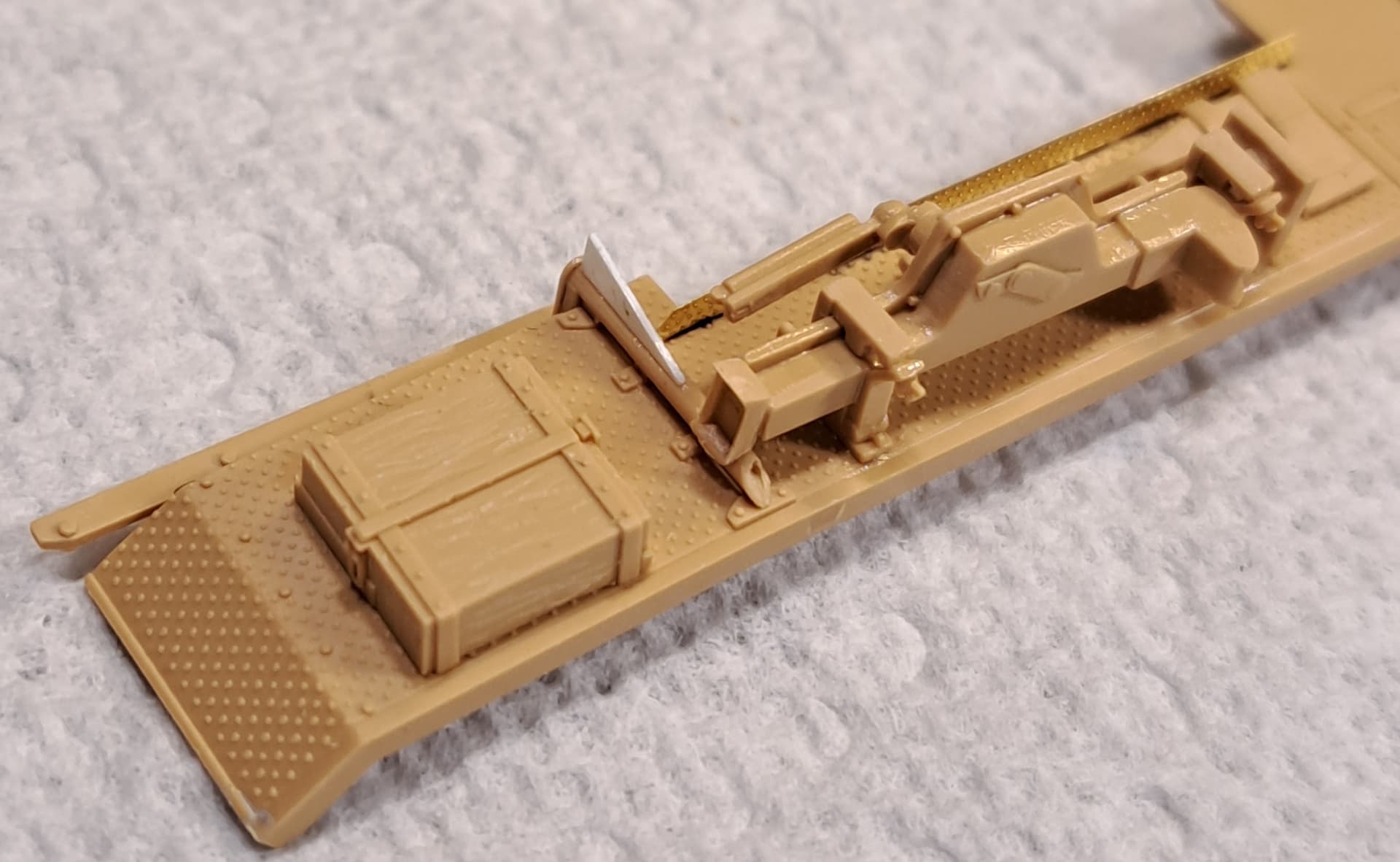
RFM’s PE tool clasp for the axe made a nice impression. The soft PE easily cleans up after cutting free of fret.
Angled view of white card stock Y3
Very happy with RFM’s jack design and plastic clasp.
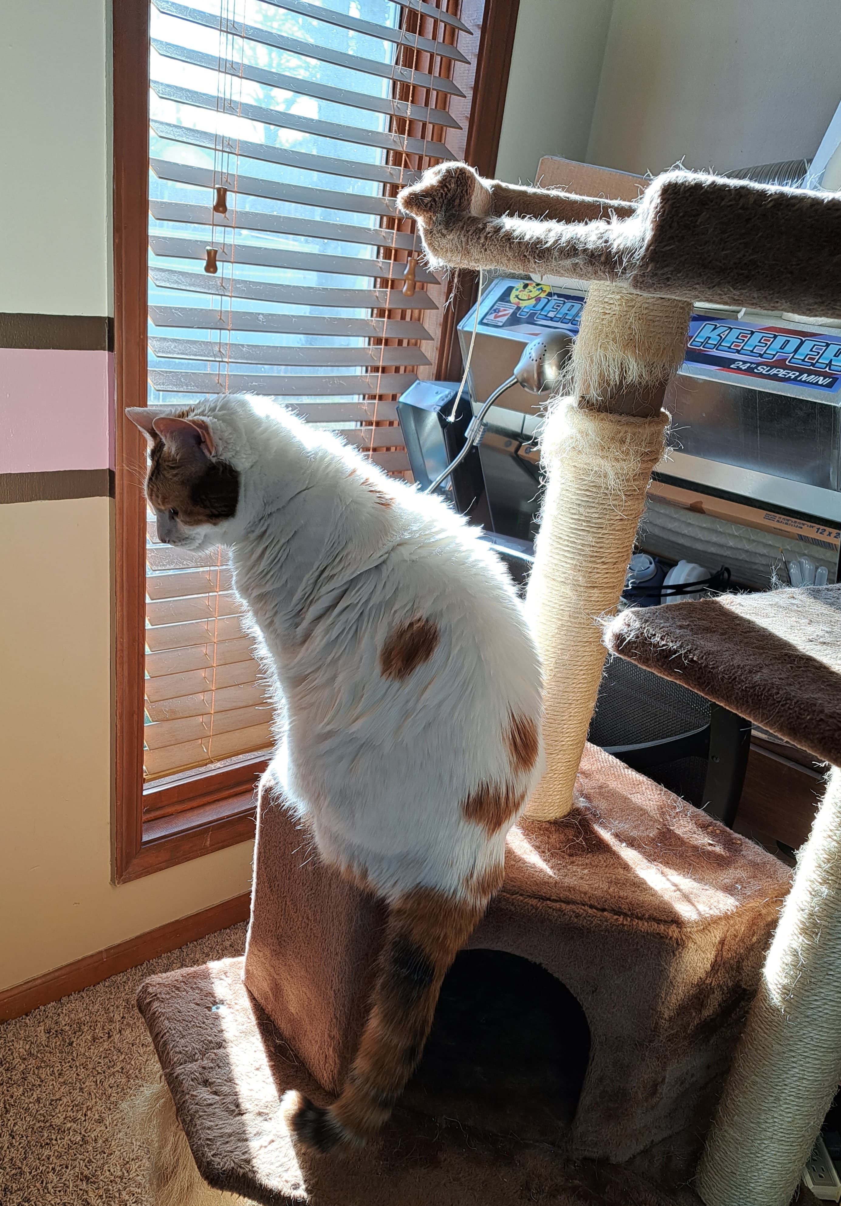
For the record, Kali finally allowed Joey back into the hobby room but not back in her cat tree.
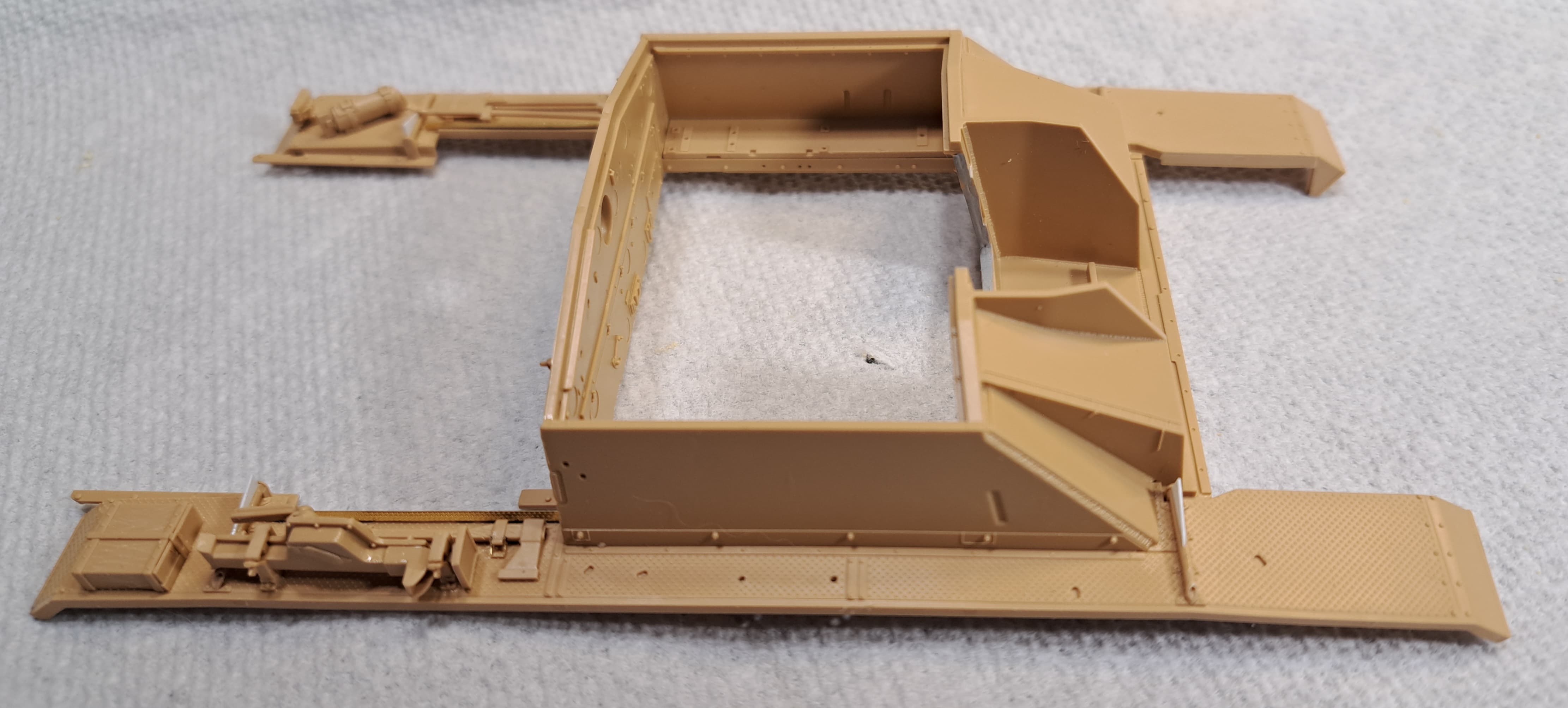
Step 13 Attach Fenders to Superstructure
Honestly, I expected a fitment issue or two given the nature of how the Superstructure assembled. Nope. Literally parts clicked into place. Amaze-Balls!
Midway 13 steps complete & 13 remaining.
That’s the kind of sag I can get behind ![]()
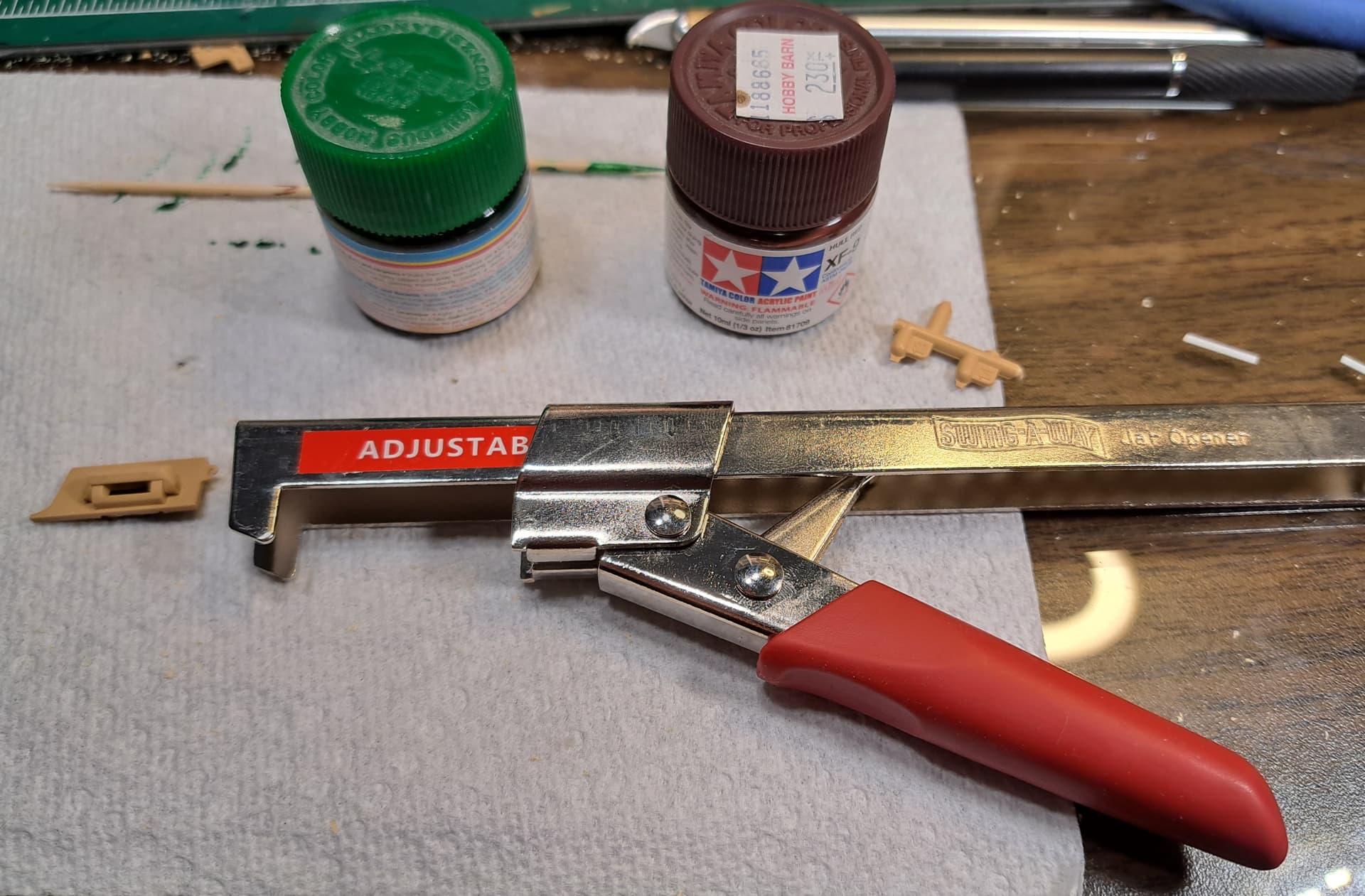
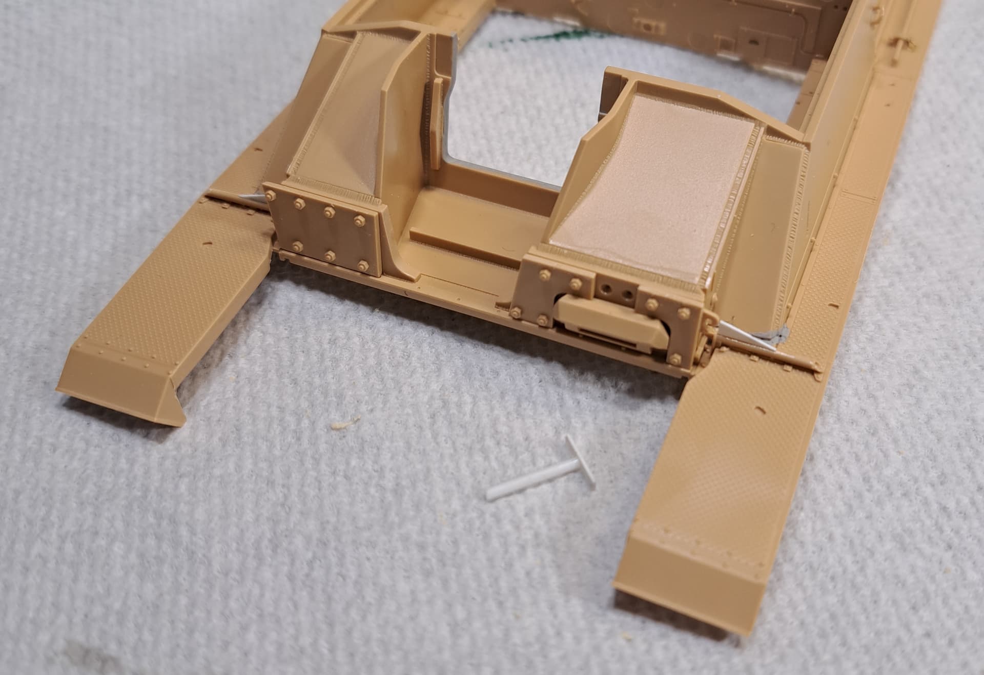
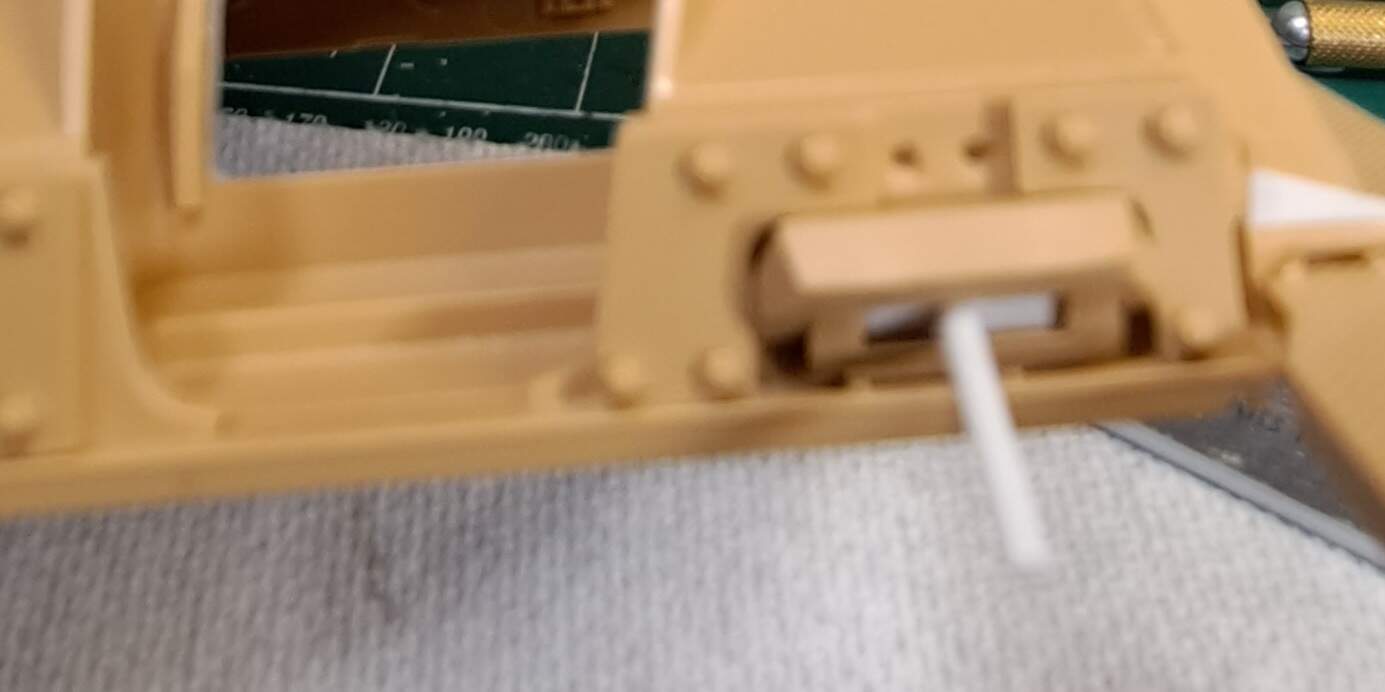
Step 14 front armor bolt on armor
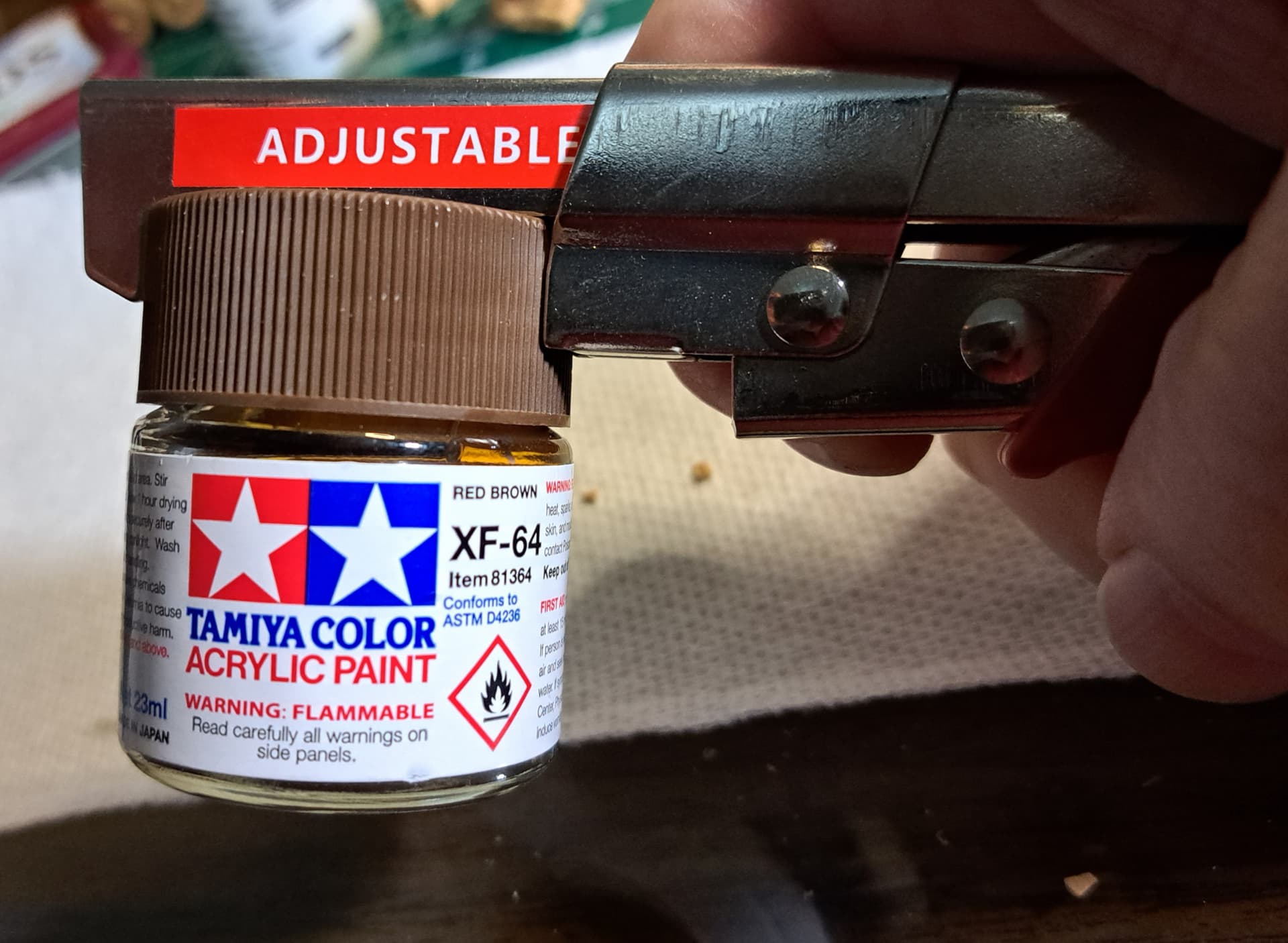
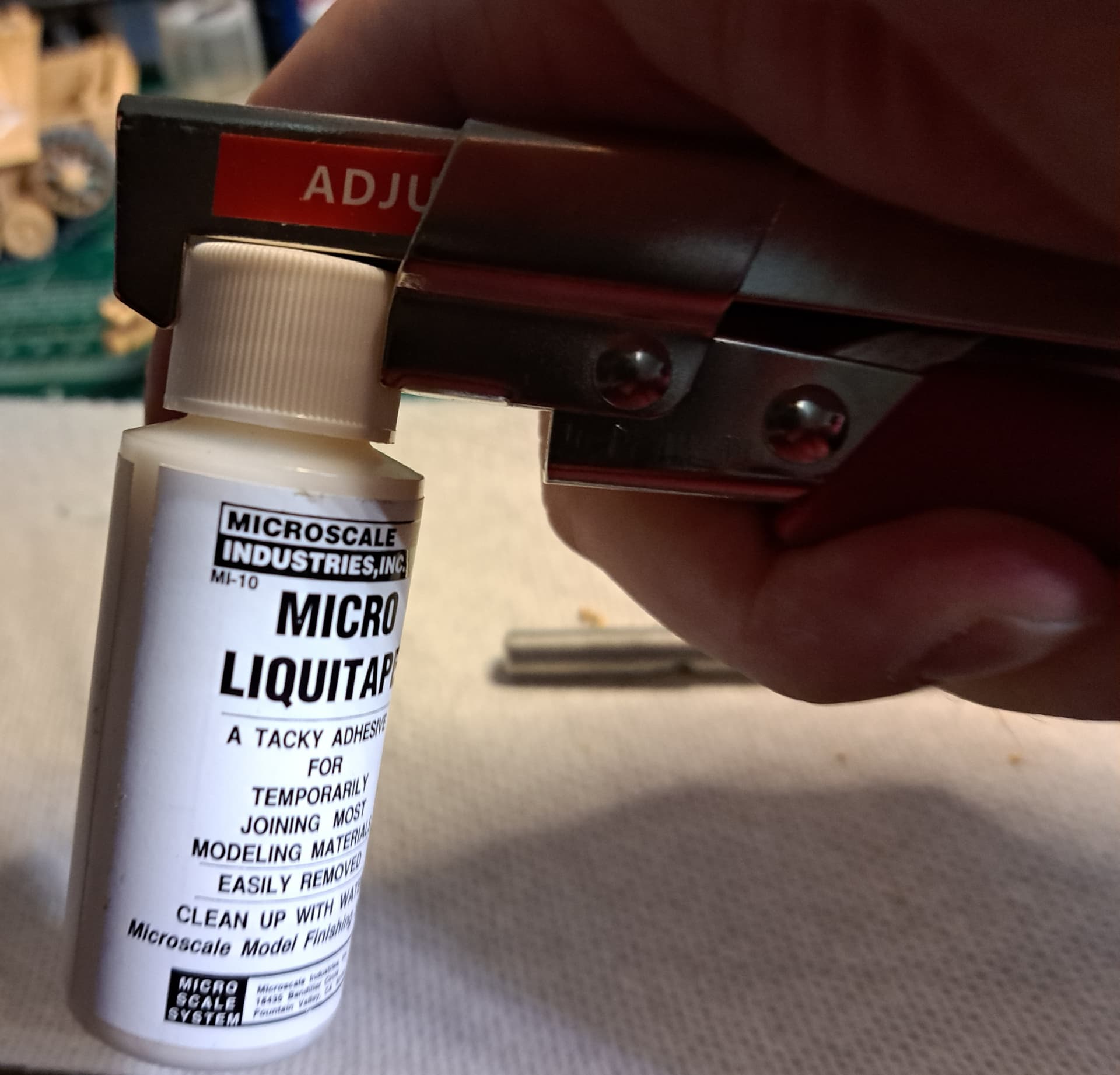
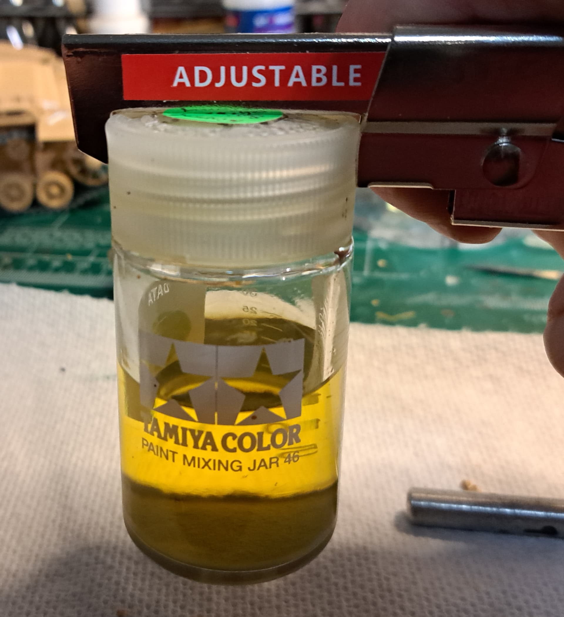
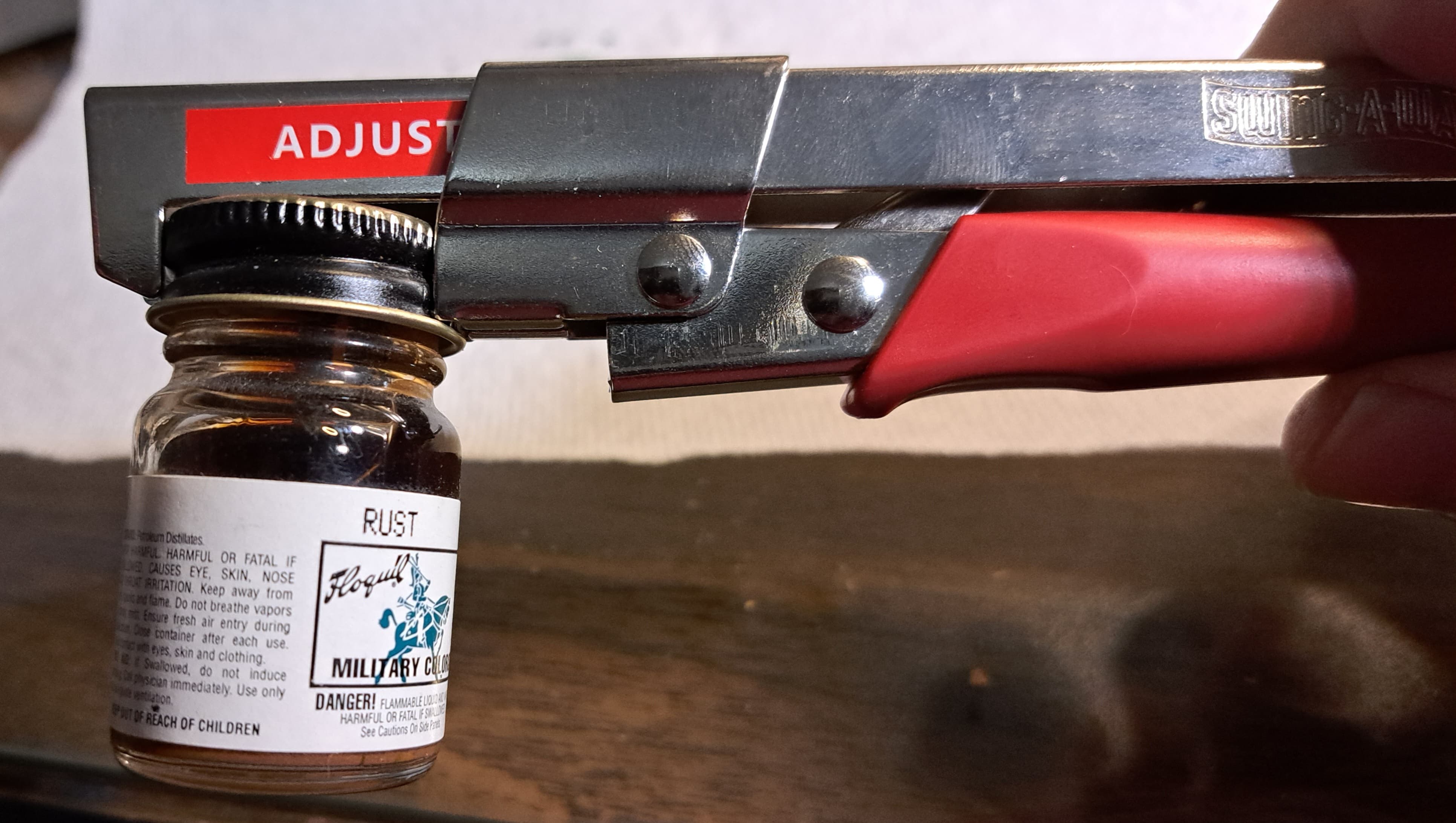
Fun step. Since the driver’s visor included clear plastic for the armorglass block decided to paint the back side. Naturally, lid was stuck tight on the paint jar. Zero issue thanks to this little gem of a tool, the Swing-A-Way. It adjusts to fit, clamps securely making for an easy open even with a stubborn jar. Don’t get just one of these, order four. One for hobbyroom, kitchen and one for mom & dad plus inlaws.
Special thanks to Matt for pointing this tool out previously @SSGToms
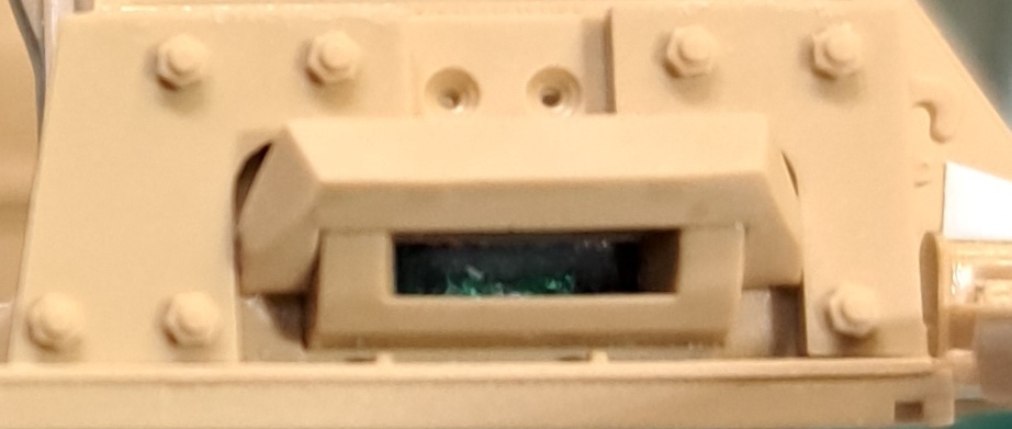
All bolted up. The white T is a mask for driver’s vision block when spray painting. Masking tape works well too.
While not a Stug III aficionado, I think RFM definitely captured the look & detail. I really like the top vision port. Nicely done RFM.
Is there a certain name or size to this bottle opener?
I’m thinking about Tamiya paints only.
Thanks
Dan, it adjusts for any and all size caps from very small to probably ~7 inch jar lid max. It will definitely fit Tamiya paint bottles both sizes and many others too.
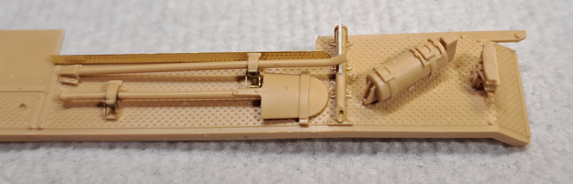
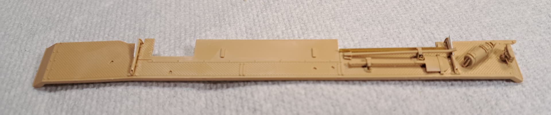
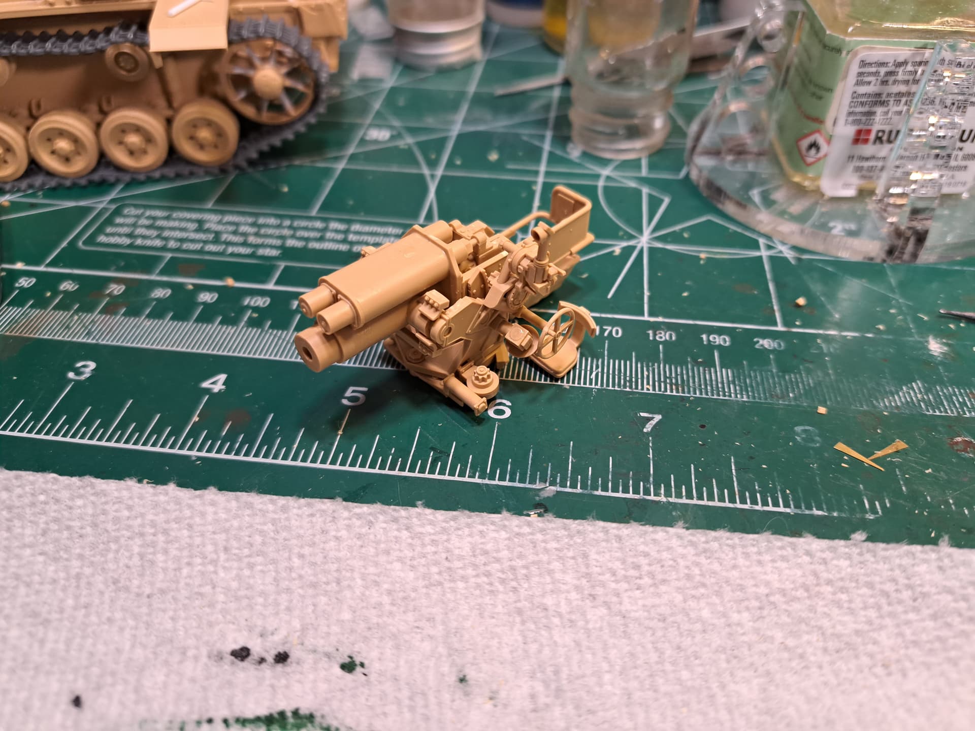
Steps 15 to 18 - Main Gun Assembly
Since the Stug will be buttoned up and this assembly won’t be visible to any degree, minimal part clean up for good fit was done. Good news the main gun is well engineered and went together with no issues.
Thanks
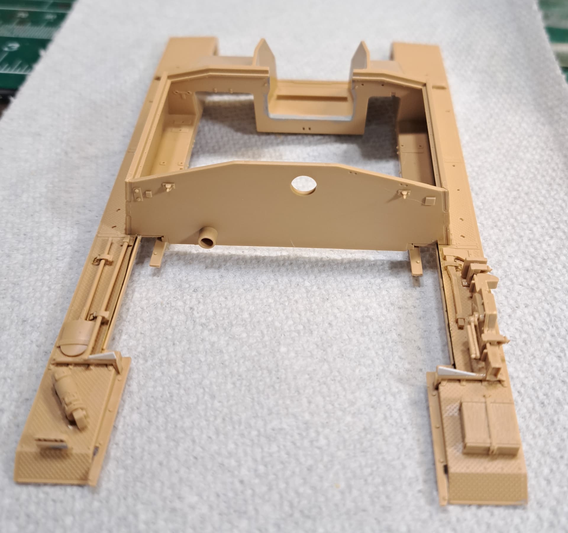
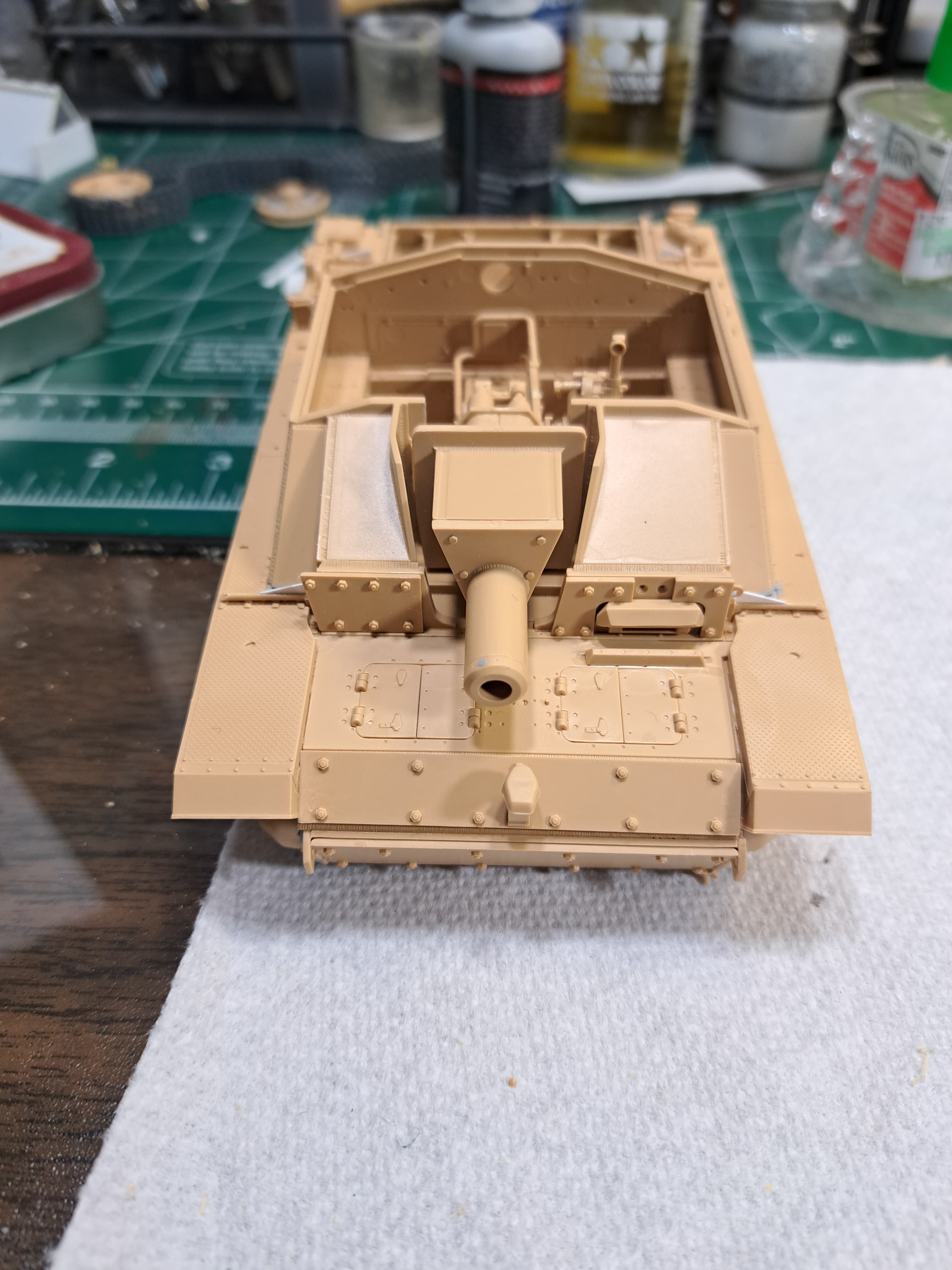
Step 19 - Main gun, Superstructure & Lower Hull Assembly - aka The Sum of All Fears
This simple step had a pucker factor for me because both the lower hull and upper hull are built from multiple parts and aren’t bath ![]() style. Slight errors in subassemblies, unnoticeable individually, can stack when combined.
style. Slight errors in subassemblies, unnoticeable individually, can stack when combined.
The test fit of the four subassemblies didn’t prove to be the precision Rolex experience I’d hoped to achieve. It quickly became apparent there was a serious fit issue between the upper & lower halves. ![]()
One suspected area of issue was subassembly parts A3 & A4 of the superstructure. Plastic squeeze made several burrs causing a fit issue. Couple of scrapes with a #15 blade removed the burrs. l should have caught that earlier. That fixed half of the fit issue.
Now that both halves partly fit together, I discovered the right hand lower hull side had warp. It bowed in about 1.5 mm’s toward the nose due to a simple misalignment I’d missed. The bowed lower hull side was easily fixed with a spreader bar made from aluminum tubing super glued into place.
After the repairs, the hull halves Rolexed together properly. ![]() Installing the main gun with mantle required a little side to side pull and wiggle on the upper superstructure. That all went smoothly other than I snagged a torsion arm for the suspension and snapped the pin for the wheel off flush
Installing the main gun with mantle required a little side to side pull and wiggle on the upper superstructure. That all went smoothly other than I snagged a torsion arm for the suspension and snapped the pin for the wheel off flush ![]() Minor annoyance with Tamiya Extra Thin. Checked alignment with straight edge and then super glued.
Minor annoyance with Tamiya Extra Thin. Checked alignment with straight edge and then super glued.