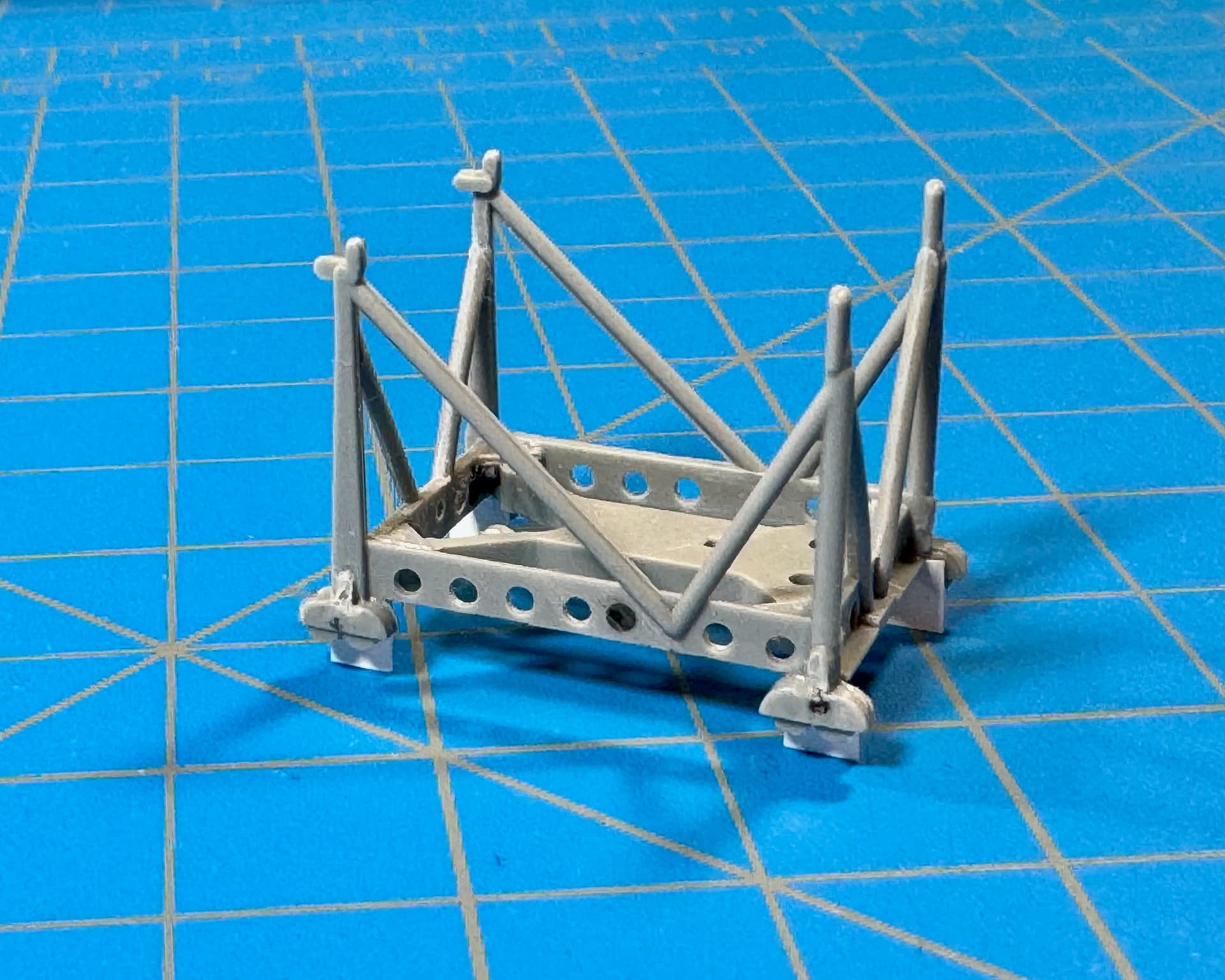
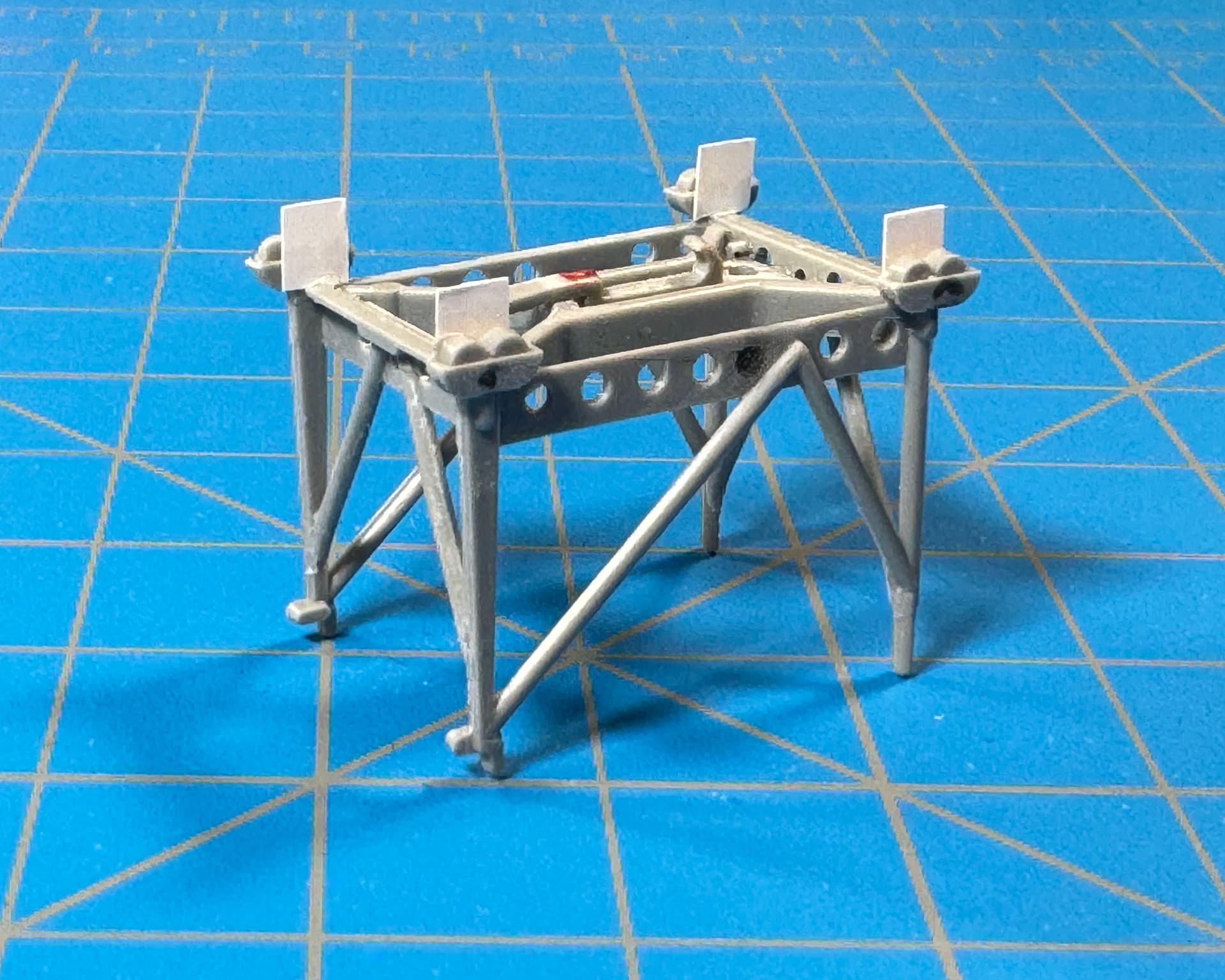
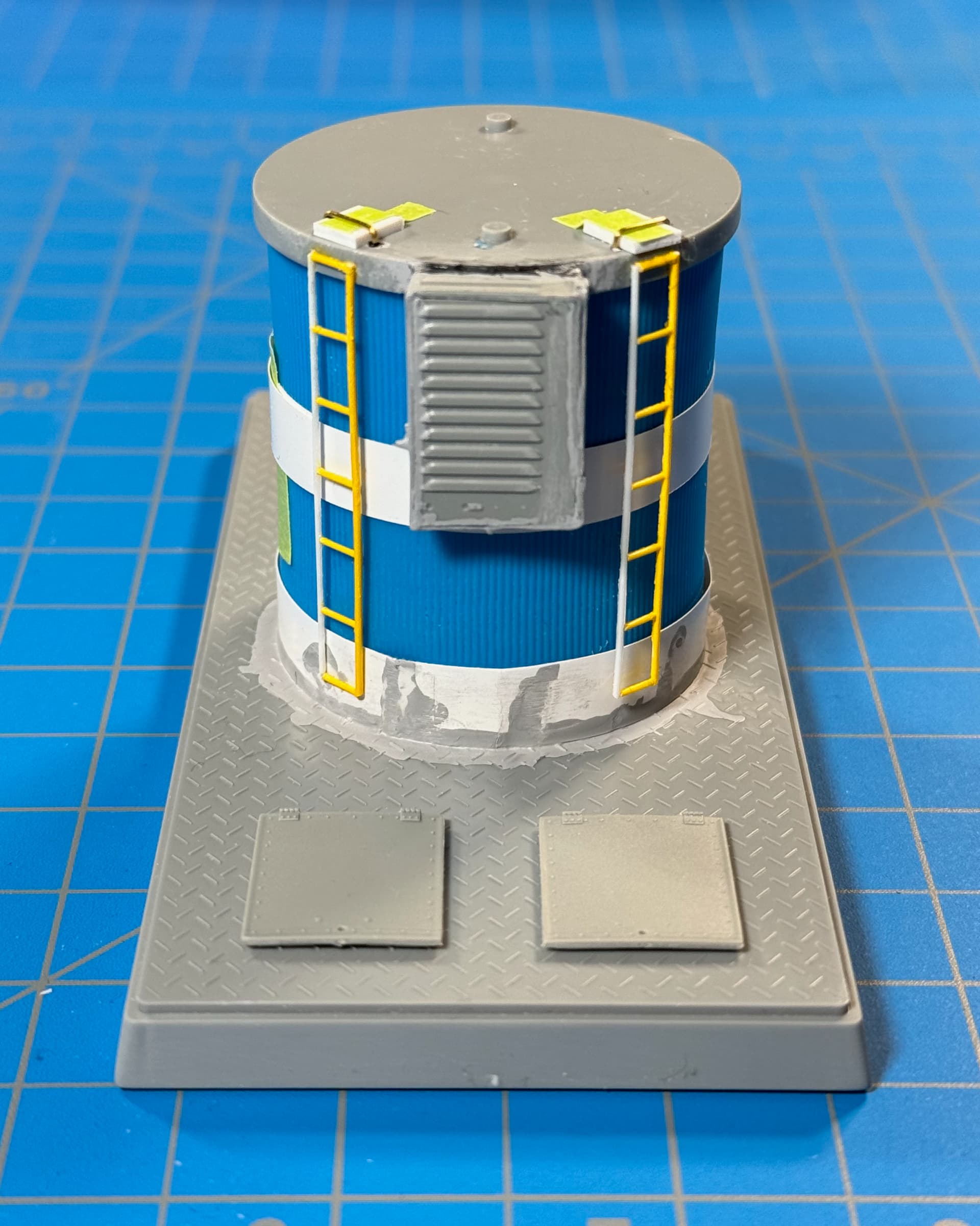
• Whatchamacallit panel scratched from spares and Evergreen Styrene. Black CA is still curing.
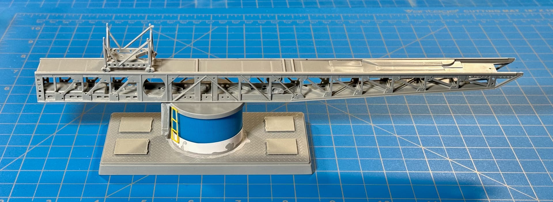
• Ladder segments trimmed from leftover scratch-built pieces.
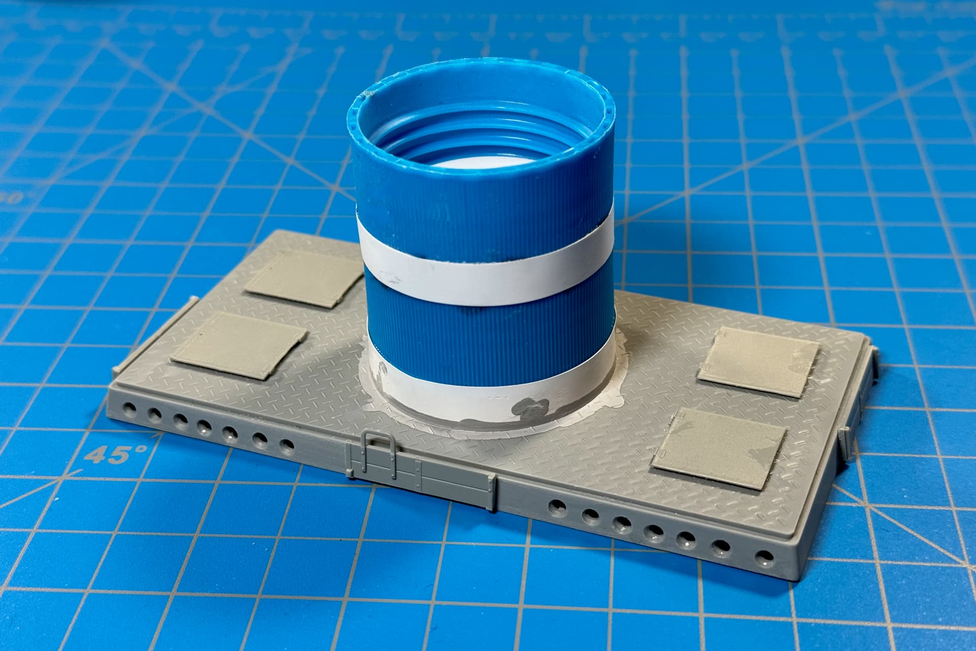
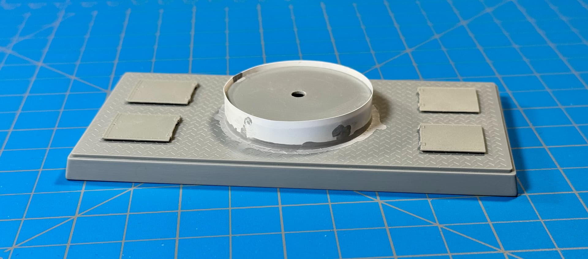
• Deck Hatches from the spares box.
Hi guys,
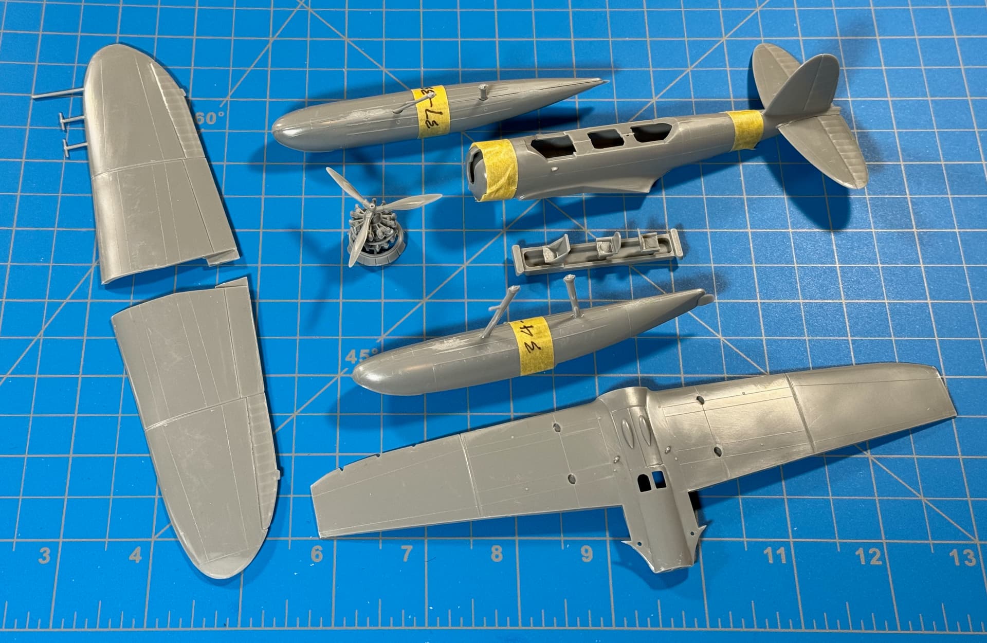
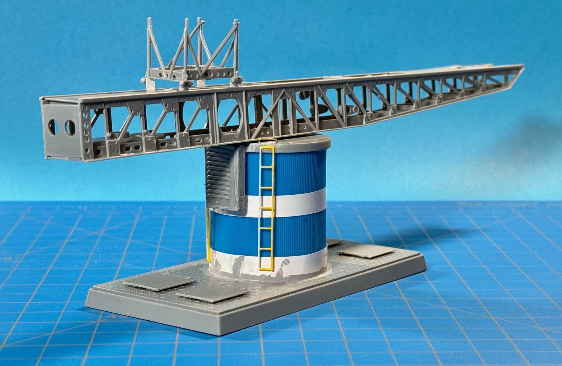
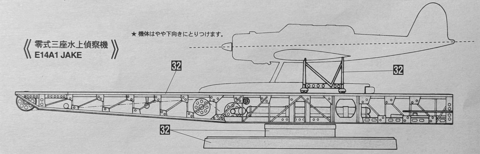
Here’s the latest on the ‘Jake.’ … well, just the catapult for now. However, I’ll have you know, I have been reviewing the aircraft instructions.
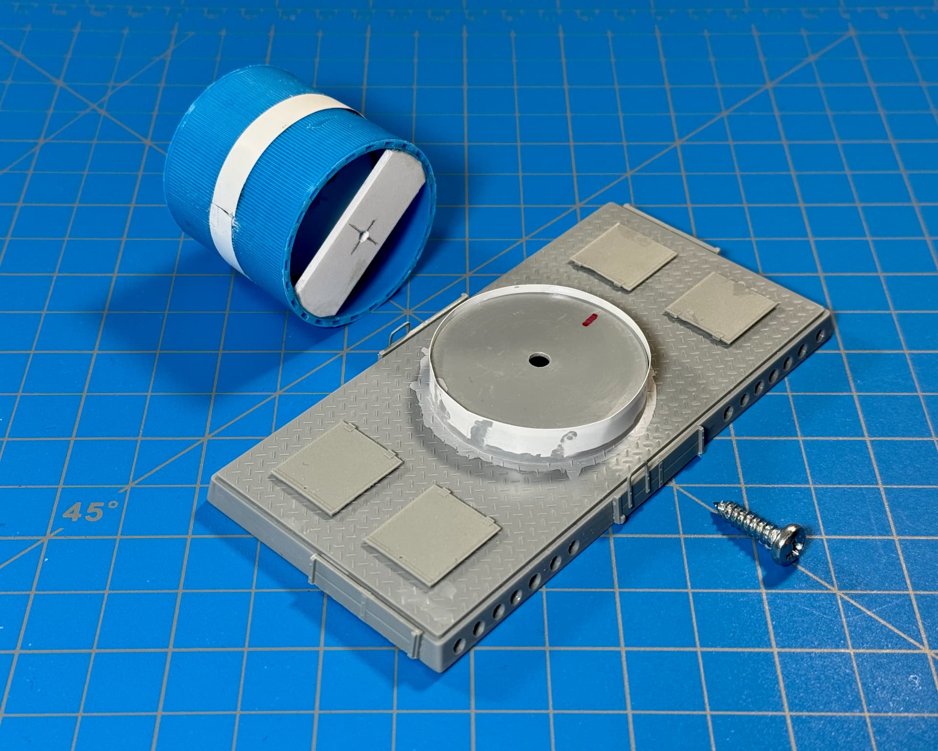
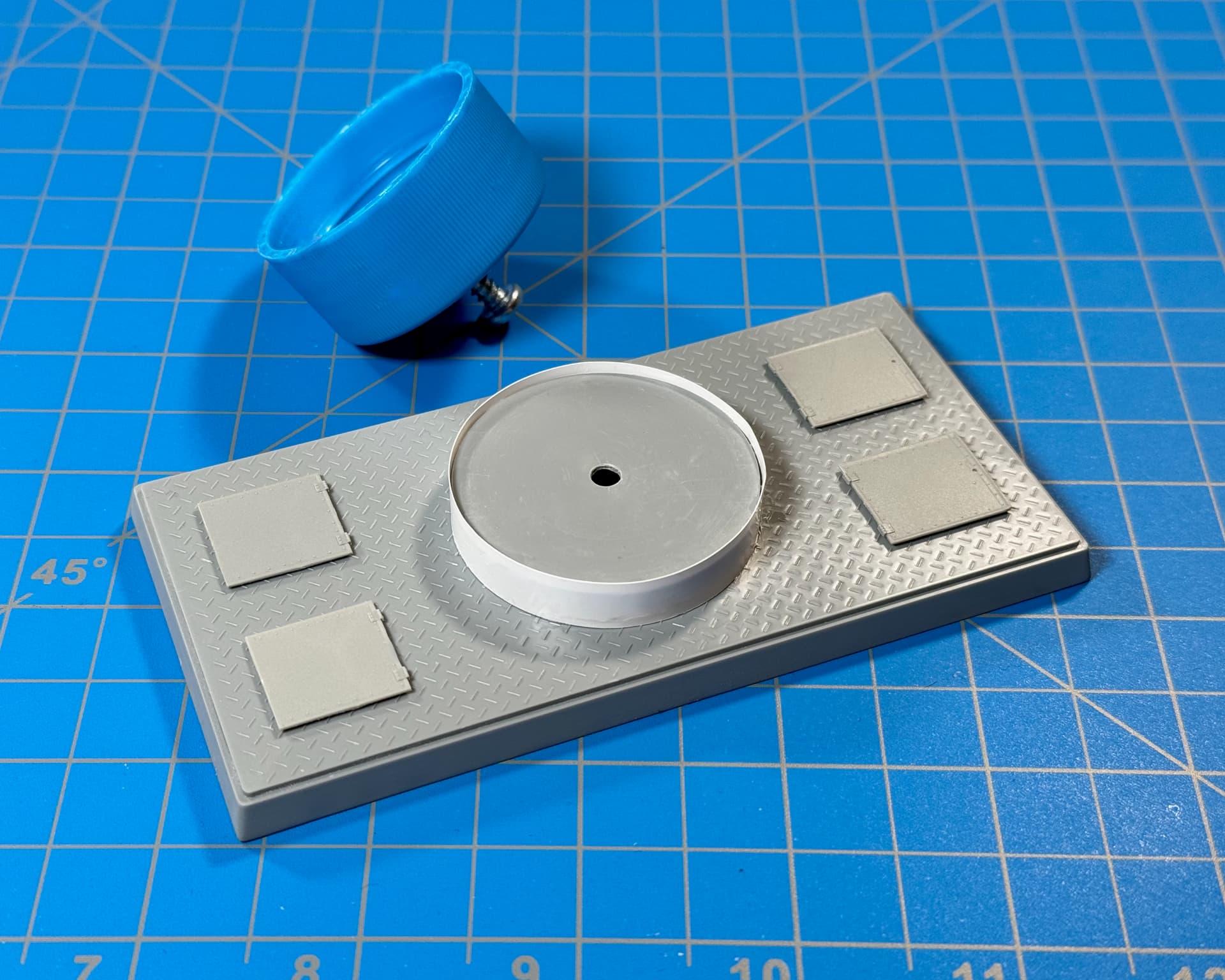
Added a ring at the tower’s base.
• Evergreen Styrene Sheet (9009) .005” Thick (0.13mm).
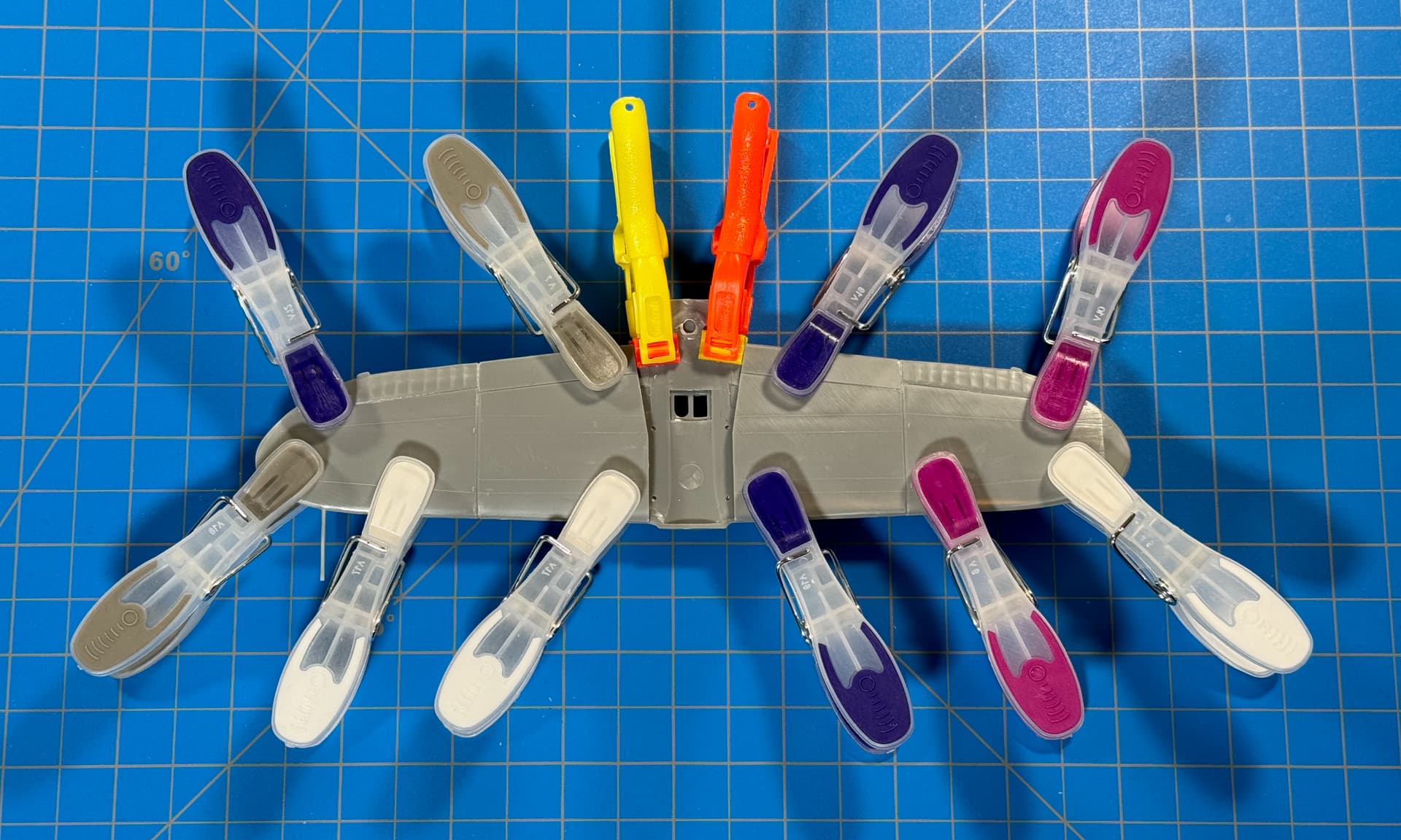
Contrary to what I said earlier about “invisible” sink-marks, there were a lot of them… some very visible. So, I hit the bottle… of VMS Flexy 5K Black CA (VMS.CM09) CA and dispatched as many as I could — very time-consuming, but in the end, I chalk it up to good practice.
Nice Mike, the height looks good. You may want to think about centre of gravity though - your base will need to be pretty sturdy to prevent sideways tipping once the aircraft is on top.
Just one Q. I can’t tell without a figure to go by, but do the ladders need extra rungs between the existing ones? They seem a bit further apart than the pic you posted:
Thank’s Peter!
The ladders are leftover scraps. If I feel like “rung-counting” that detail, I could always add more.
The base is kit provided. I believe the center of gravity issue would be the same whether short or tall. However, I don’t trust it either. So everything will be attached (bottom pivot screw). In addition, I’m planning on adding weight and/or mounting the assembly on a wooden base.
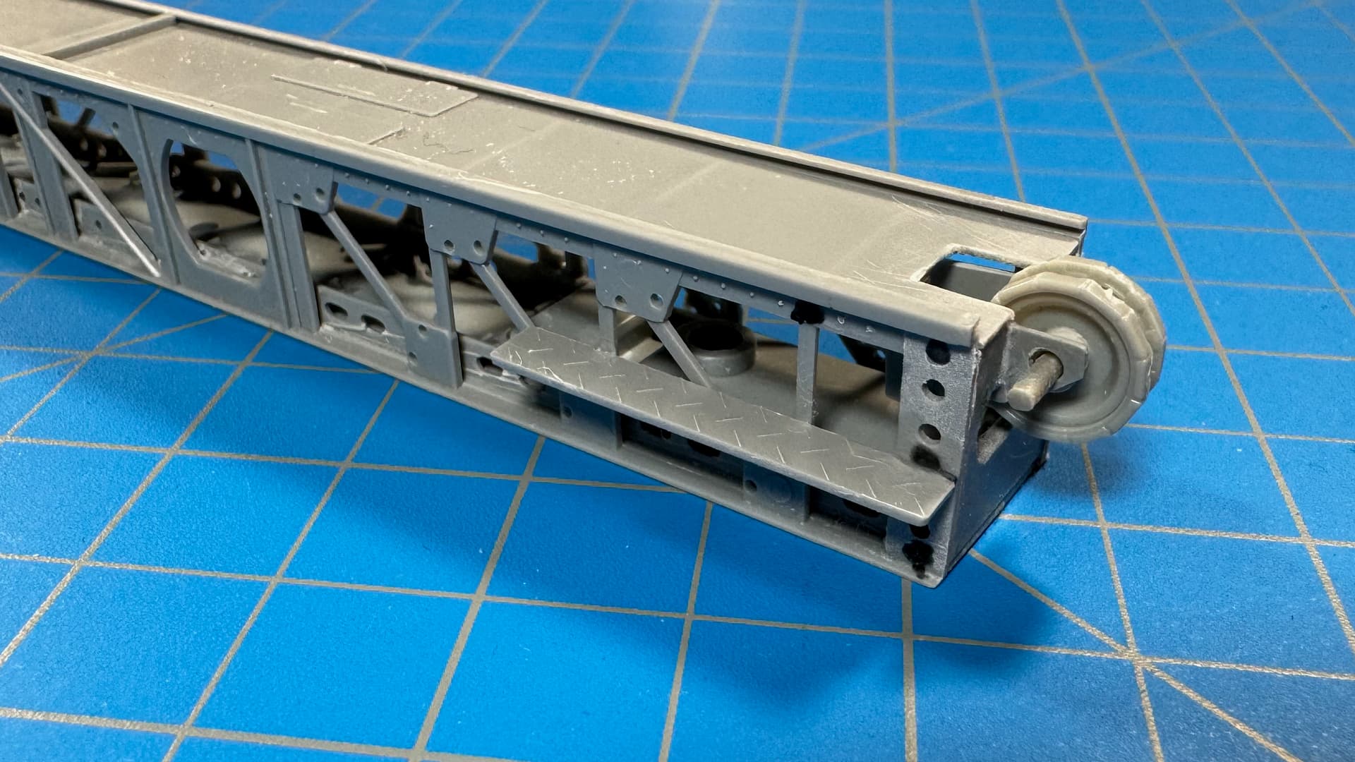
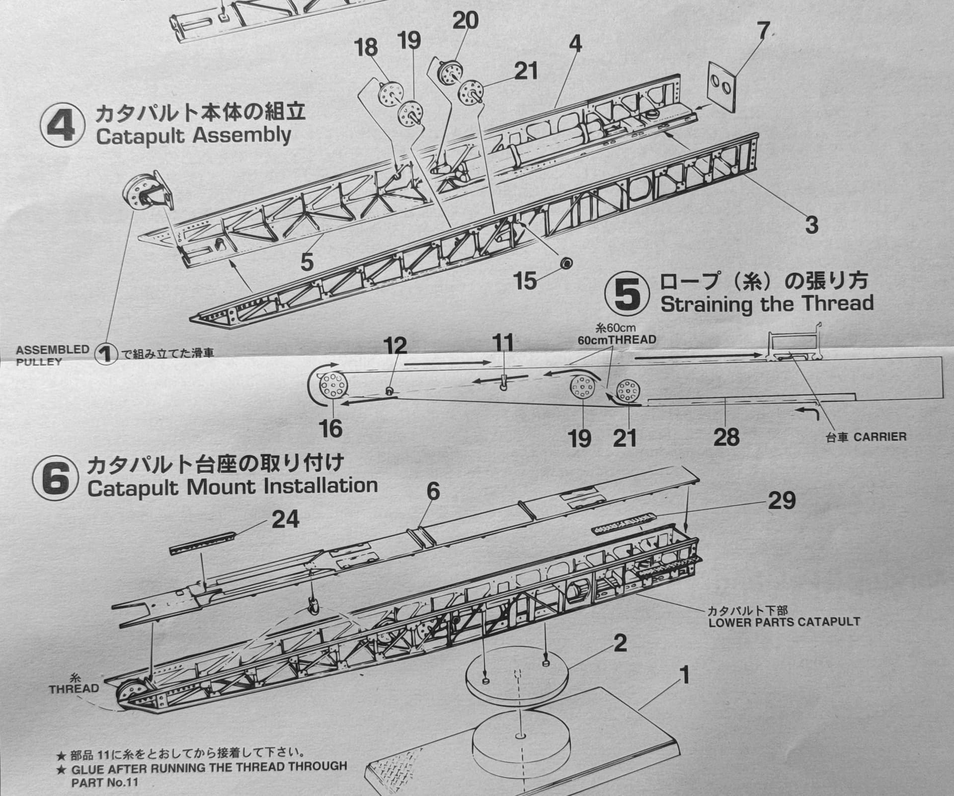
Now here’s something for you guys to chew on… The kit instructions show threading the catapult from the launch carriage to the nose of the structure around a large pulley, then back through the inside and through a system of guide pulleys to the rear and to what I presume are three compressed air cylinders or possibly a steam system. My question is… How does the cradle return back to the rear of the catapult? There’s a hook under the carriage, but there doesn’t seem to be a return mechanism.
I expect the Japanese system would not be too dissimilar to the British one of the time and the trolley has cables on the rear too. The trolley would be returned by activation of a motor and using the pulley system. The kit is pretty basic and probably would not show all of the mechanism on the real thing.
The British one:
See about 8.15 in for the trolley being brought into launch position and about 15.50 mins in for a good clear shot of the cables on the trolley rear.
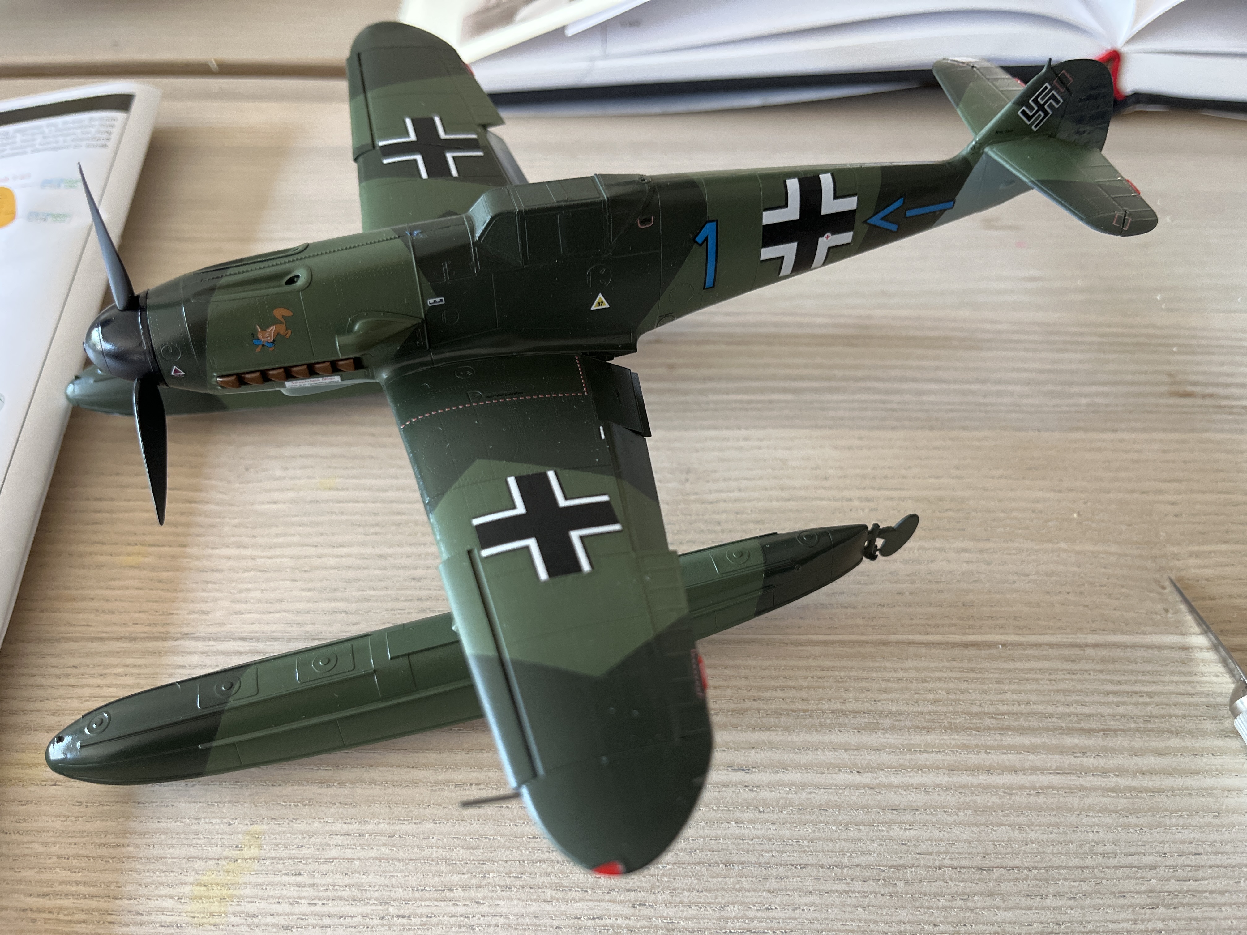
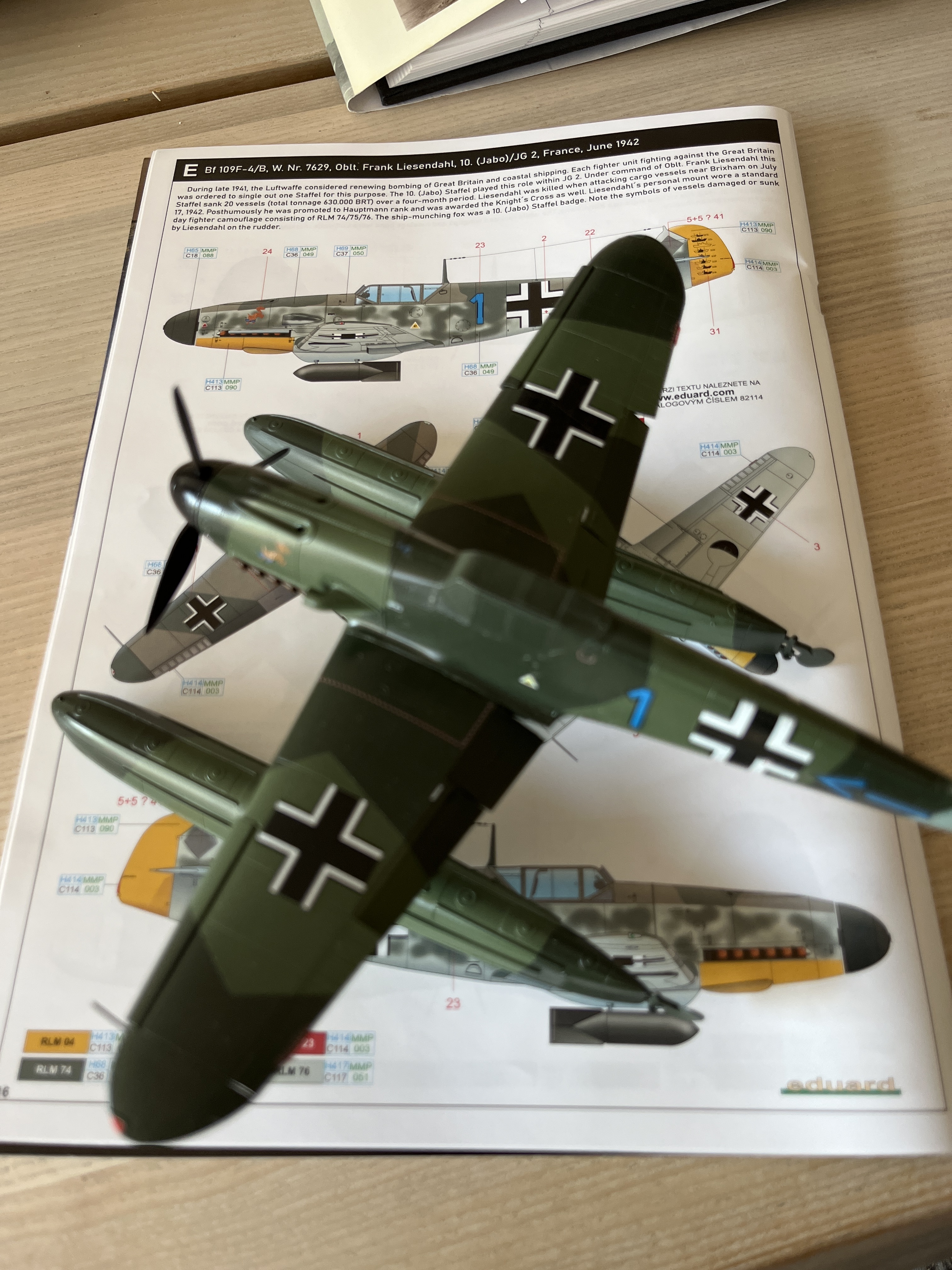
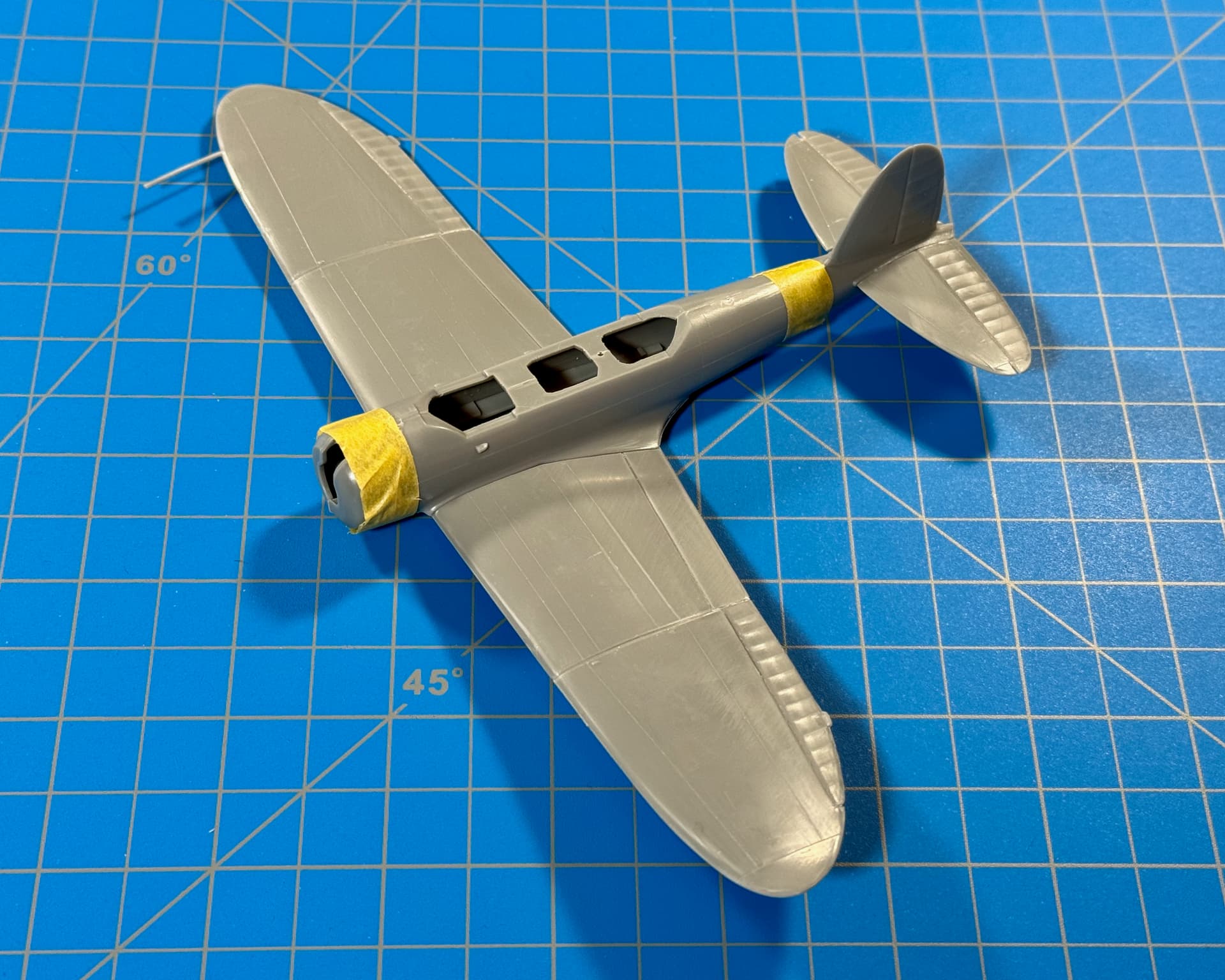
I went with your advice and avoided the squiggles. Decals are now on. I went with the eduard decals of a Bf 109F that was used for ship bombing in the English Channel. Seems like a plausible fit.
Next is perhaps a second coat of decal solution will be necessary. Then it is of for a final coat before a very light weathering.
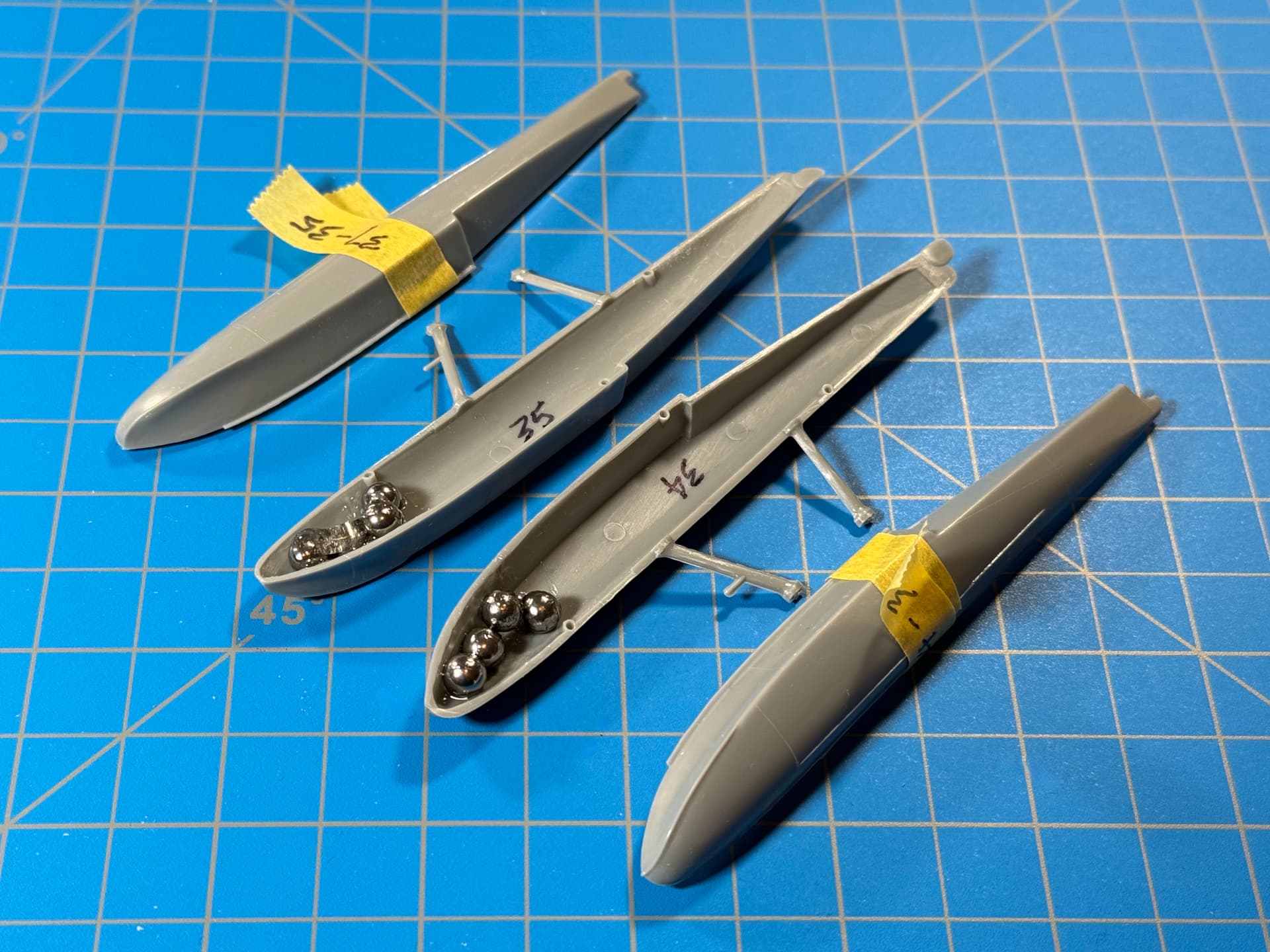
I seem to recall a rumor “floating” around, that Jake is a tail-sitter. So just in case, I added a bit of weight with a few stainless balls and some Gorilla Epoxy.
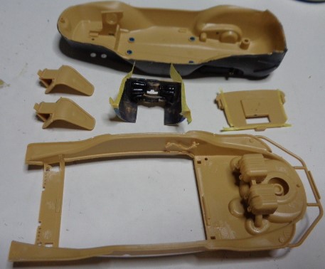
I started by using some Micro Mask to fill in where the interior will fit in the chassis bottom and masking tape for the engine compartment and wall. Usually I would paint then scrape away paint from the areas where glue will go.
For some reason, I decided to add things to the top of the body like the fuel tanks, the fuel tank covers, and the tire mount, and the weird little pipe (part B53) you see on the inside. Evidently, this is an earlier example of Tamiya using shallow dimples to show where a part goes. There is a corresponding part of the other side. I didn’t like on the M51 Sherman track guard braces and I don’t like them here. Also glued were the front chair mounts and a divider in the chassis.
That is an engine starter crank Gary. The piece has the clasp and the socket type fitting that it is slid into moulded on it. I am not sure if it actually goes there or not. Most restored ones have a twin drum magazine for the MG34 fitted vertically there.


")