Space Shuttle Launch Complex 39A with Challenger STS-6 (1:144)

Hello everybody,

yep many modifications have been made throughout the Space Shuttle program, and so each Shuttle mission had its own characteristic features which set it apart from other missions. And that was the difficulty for me at first, because I collected lots of photos that showed special details that I was particularly interested in.

But since I lastly decided me for the Challenger’s STS-6 mission, I had to put a lot of photos aside. And so I had to live with the problem to this day that there are relatively few reference photos of the STS-6 mission as one of the early missions in high resolution that I could use for my scratch building of special details.

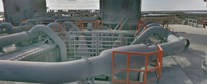
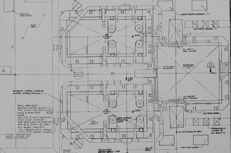
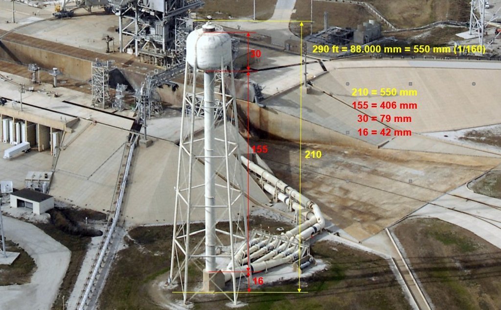
One of the photos is this shot of the Challenger on the launch pad during STS-6, which has remained my standard reference shot to this day, as it shows a lot of details of the FSS tower and the RSS as well as the MLP-2, which was used during this mission.


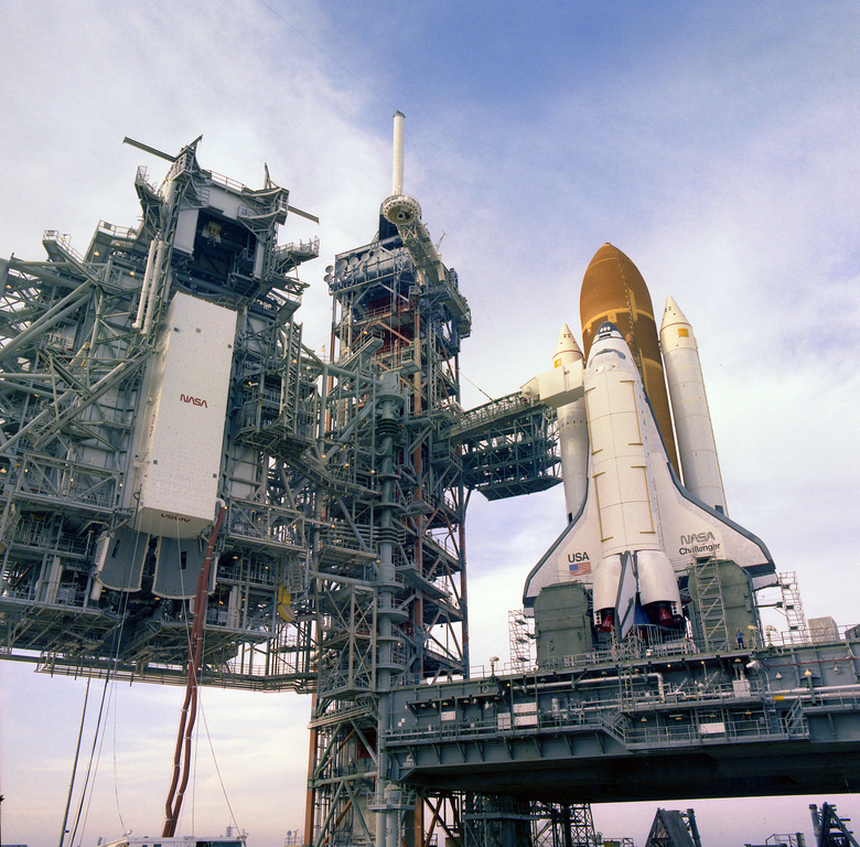
Source: retrospaceimages.com (STS-6)

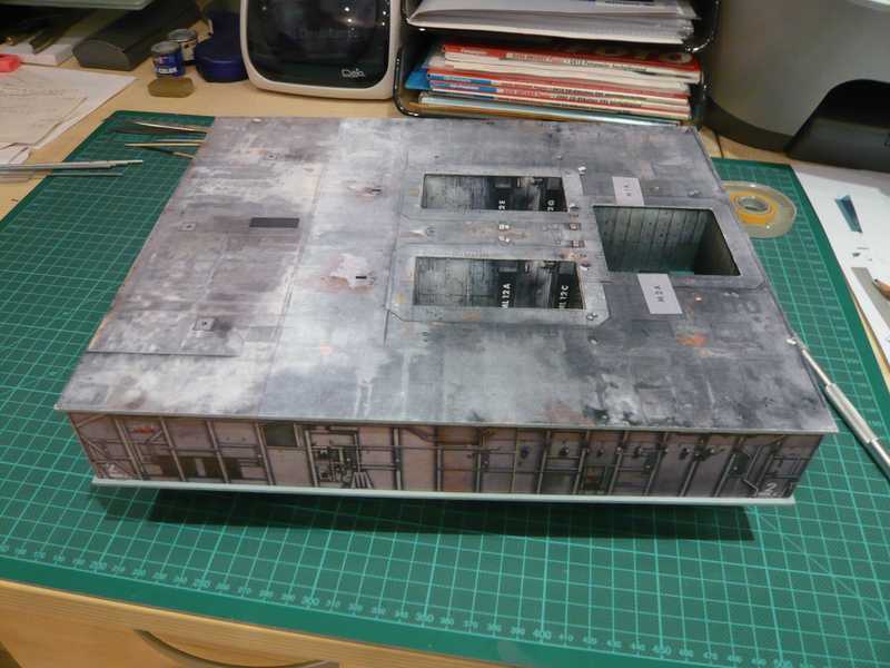
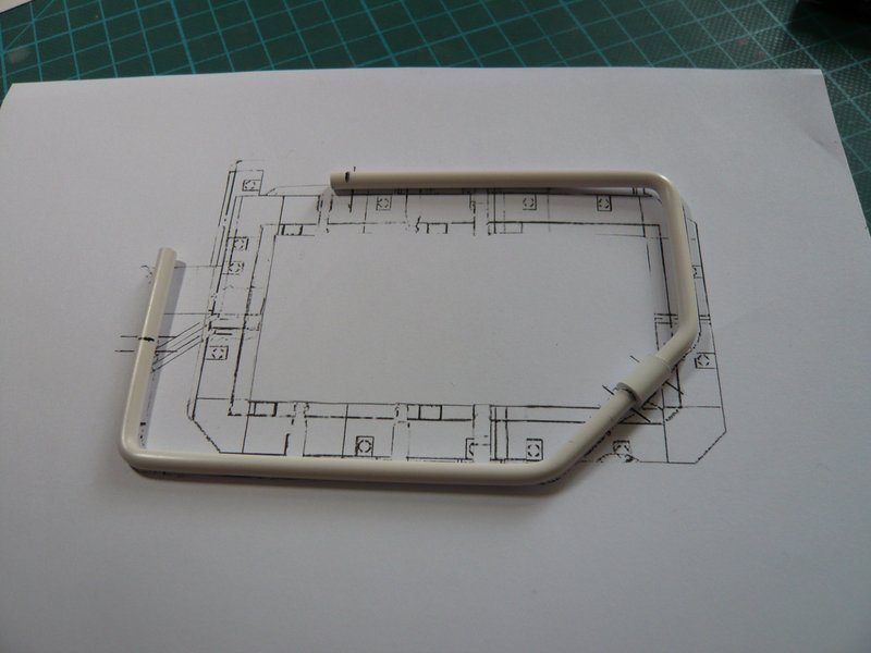
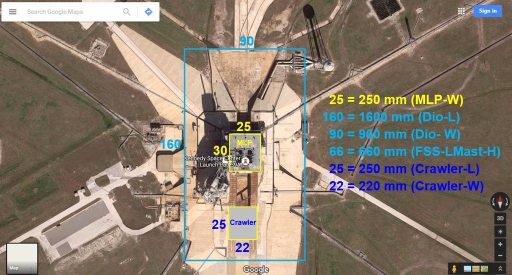
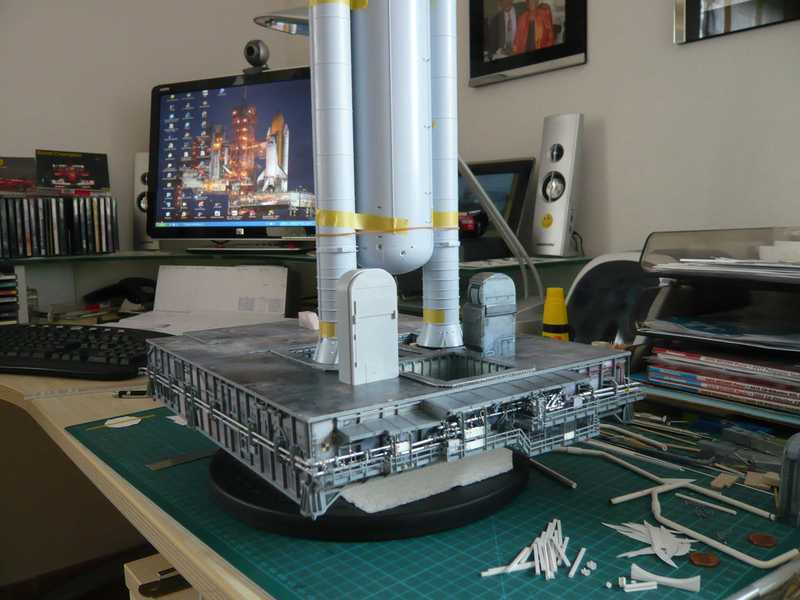
And when I started building the MLP, I’ve been looking for images of the MLP-2 since the other two MLPs, MLP-1 and MLP-3, had certain differences.

And when John mentions the color scheme, then that is also an important aspect, especially as far as the STS-6 External tank (ET-8) is concerned, which one can clearly see when one compares this image after the rollout (08/12/82) with this one from the Challenger launch (04/04/1983) on which the ET looks darker orange due to its foam insulation (SOFI ) degrading due to longer exposure to sunlight, because the Shuttle Main Engines (SSME) had to be exchanged.
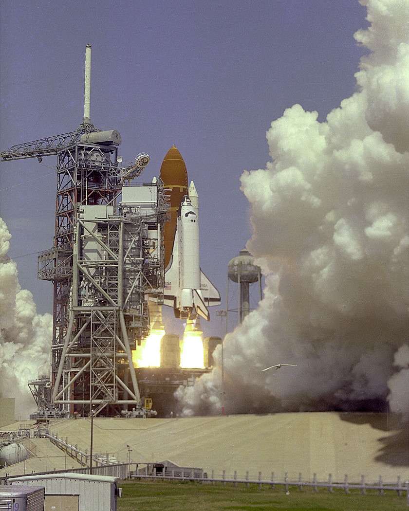

Source: NASA

2 Likes

Some absolutely cracking images here and a lot of hard dedicated research…

As a former scientist and materials researcher, I’m usually interested to know how things worked in addition to the equipment details.

And regarding the different NASA logos, I noticed during building the Astrovan, because I found out in my research that the STS-6 Astrovan had the Worm logo and not the Meatball that one were used to from the last missions.

In this photo one can see the STS-6 crew with Story Musgrave in the lead getting into the van. This is clearly the older box-shaped white van model, a modified Clark-Cortez motorhome, but unfortunately the logos on the sides are not to see in the photo.


Source: retrospaceimages.com (J. L. Pickering, STS-6)

After that, I went back even further, to the STS-1, with which the shuttle era began, and I found this insightful NASA photo on which the van at the time had the Worm logo.


Source: images.nasa.gov

Step by step I got closer to the STS-6, whereby according to my logo philosophy I assumed that the van at that time probably also had this Worm logo, which had to be proven.

And last not least a friend from our German Raumcon Forum sent me a Tagesschau Video round about the maiden flight of the Challenger (STS-6), what finally provided the clear evidence that the Astrovan at that time carried the NASA Worm logo. So I was actually at the goal of my search.


Source: ARD Tagesschau

And my NSF friend Elmer (EG) sent me a link on which one can download a Paper kit of the Astrovan, which I will simply build, initially in 1:48, but then also to match my diorama in 1:160, but with the correct NASA Worm logo, in order to fit for the STS-6.

And how I started scratch building this Van using this paper kit first in 1:48 you can follow it here.

And on Christmas Eve 2021 the Astrovan (1:48) was completed.

And then I started with the little Astrovan (1:160) with the Worm logo for my STS-6 diorama.

And the comparison with the large Van model (1:48) shows in an impressive way how small this Mini Astrovan (1:160) really is, which now also fits with its NASA Worm logo with my STS-6 Diorama.

All in all, the construction was an attractive, but at the same time demanding task, a real Challenge, so to speak, and made a lot of fun.

4 Likes

Nice looking Astrovan. It will sure look cool on your diorama. Btw, did you also build the Christmas Eve decorations pic next to the 1/48 astrovan? Very creative and I love it.

1 Like

Thanks Mike,

it’s nice if you like the small group of deer. This is original carving from the Ore Mountains around Annaberg-Buchholz.

1 Like

:thinking: sounds like an interesting story hidden within this. I will have to look it up.

It’s OOT, therefore I’ll tell you about it in a PM in ARC.

1 Like

Hello everybody,

after struggling with the scaling dilemma of the Revell Kit 4911 for a long time, I started building the Mobile Launcher Platform (MLP). For this I used David Maier’s Paper Kit (EDU-Craft Diversions, 1:144), which I had let reduce to 1:160.

I didn’t build the substructure out of cardboard but out of Balsa for more stability.

I then glued the parts of the kit onto it like wallpaper.

You can follow the further building of the MLP here in the NSF.

A particularly difficult and demanding chapter at it was the scratch-building of the MLP’s Sound Suppression Water System (SSWS),


Source: NASA

what consists of many bent tubes, what you can see here in Google Maps where you can scroll around.

https://www.google.com/maps/@28.608281,-80.604157,3a,75y,97.91h,82.9t/data=!3m5!1e1!3m3!1sDHj39f-OZvUENKY1pLy9aw!2e0!3e5

For this SSWS I came up with an ingenious Balsa-Pin & Bending Technique, which has since brought me a lot of praise and recognition of my followers in other forums, what you can follow here.

The most important device for doing it is this Hot air gun.

Then all you need is Balsa boards, pins and templates with the shapes of the tubes, which you can bend then stepwise under hot air.

And this is what the first ring line looks like.

Before bending of the second ring line I still wanted to check their position on the MLP, here initially on the sketch from this NASA drawing,


Source: NASA

to which it fits very well.

Thanks for watching so far.

10 Likes

That is a great update … And the jig for the pipework is a feat of engineering in its own right !! Brilliant

1 Like

Thanks John for looking in on me again. :clap:

Without this clever bending technique, it would have been impossible to reproducibly produce these differently bent tubes, which is why I can be justifiably proud, especially since I could use them for many other applications. :+1:

2 Likes

Very interesting project. But which scale M113 will you go with?

1/160?

Or 1/144?

2 Likes

Thanks my friend for your interest.

As I have written at the beginning of my thread, I have decided me for 1/160 in order to deal with Revell’s scale dilemma.

Hello everybody,

however, these two ring lines were only the first step into the branched SSWS around both Solid Rocket Booster (SRB) exhaust holes which has six curved outlet pipes, some of which are also tapered, which one can see in this image (green),


Source: NASA

and in this image here.


Source: NASA

This main pipe system is connected to a subsystem, which is located around the SSME exhaust hole, whereby during launch the entire MLP deck is flooded, as seen here in a SSWS test.


Source: NASA

Then there are the six Rainbirds (red), for which I had thought of a special technique for the ‘screws rings’ similar to Billy the Kid’s cartridge belt, :cowboy_hat_face: what I will show still later.


Source: NASA

All the details of the Ring pipes system and Rainbirds you can see in this impressive panoramic view,


Source: nasatech.net

and also in this Google map again.

https://www.google.com/maps/@28.6083864,-80.6040063,2a,75y,178.58h,103.68t/data=!3m6!1e1!3m4!1sYEsdPzSul7OBgijDqg5xMw!2e0!7i13312!8i6656

The SSWS includes also respectively 30 Water bags, which in addition are hung from above in the SRB holes and are intended to support the sound suppression effect.


Source: NASA

The following drawing gives an overview of the SSWS with details of the respective tube diameters, which were very helpful for scratch-buiding,


Source: NASA

for what I had already procured the necessary Styrene rods with diameters of 1 mm to 6 mm.

Thanks for watching.

1 Like

The old M113A2 Rescue Vehicles. :+1:

1 Like

At 1/160 scale, knowing the M113s were stationed 9/10 mile from the launch tower, that’s still 33 actual feet on a 1/160 diorama. That may pose a slight problam…

Hello friends,

I don’t know if you scrolled up to page 98 in my NSF build report,

in which I have drawn the floor plan for my Diorama in the Scale 1:160 (1600 mm x 900 mm) and marked the MLP and the Crawler.

The bunker for the M113 armored personnel carrier is about 1000 ft from the Launch pad, so it is out of the question for my diorama, interesting as it would be, which would otherwise have to be 3800 mm wide.


Source: NASA


Source: capcomespace.net

Here one can see some more details of the planned Diorama.

With an extension for the water tower as a distinctive feature of the Launch pad.


Source: NASA

The FSS and RSS I took over after the death of my Raumcon forum friend Thomas Emberger († 2017) from his wife as his legacy in order to keep an honorable memory of him on my diorama. May he rest in peace …

4 Likes

I know you’ve decided on 1:160 scale, but just wondered if there’s an opportunity to greatly increase the scope of your diorama by using forced perspective? It’s an idea that’s been discussed elsewhere in these forums, and certainly works for purely photographic purposes. Here’s a 1:72 Ferdinand in the distance with two 1:35 ones in the foreground, in reality only 30 cms or so distant…

I’m not sure if I’ve seen the same effect used in a “real” diorama - by that I mean I don’t know if it works as well if the diorama was viewed at a Show for example. But if yours is likely to be only seen in photographs it might be worth considering, provided of course you can find (very) small-scale versions of vehicles etc. that were in reality much further away from the launch pad.

2 Likes

Thanks Tim for your interesting idea, I was thinking of something similar already.

I could well imagine a panorama background image like this on the back of the diorama with a view of the VAB, possibly with a continuation on the right side.


Source: Google maps

https://www.google.com/maps/@28.6084684,-80.6046269,3a,64.4y,269.3h,102.69t/data=!3m6!1e1!3m4!1shcCciPCQZDU7s4-vUpF3iw!2e0!7i13312!8i6656

1 Like

Hello everybody,

and the Panorama Wallpaper behind the launch pad could look something like this, which would form the back of the diorama from the VAB to the LOX tank, on which the side wall would then be attached and extend to the Water tower.

Only a first imagination.

3 Likes

Hello everybody,

just when I was about to start bending the outlet pipes into the SRB holes, I encountered a problem that was related to my decision for the compromise to build the MLP in 1/160, which unfortunately only became apparent much later and had serious consequences.

You can follow it here:

When measuring in the SRB holes for the arrangement of the water bags in front of the Hold down posts I have checked the location of one SRB and got a mild shock.

The size and location of the SRB template indicated me that there would be a very serious problem with the 1:144 Shuttle stack which I totally must have lost sight during the former MLP construction according to my analysis of the scale dilemma of the Revell Launch Tower Kit with its Mini-MLP (1:200).

As you can see, the attachment points of the SRB on the front two Hold down posts sit about on its front edge and therefore too far forward. That would in itself not broken, if you would lay both Hold down posts accordingly further forward, though for the pipe down almost no place would more.

But this is unfortunately not a solution if one imagines now the location of the shuttle stack with the mighty ET between the SRBs. At that thought, I got a queasy feeling in the stomach and had to bite in hindsight in the butt me.

How could I that overlook at that time only, would fit the spatial geometry of the stacks in 1:144 inevitably not to the MLP-scale of 1:160. But since then I have focused in my heat only on the construction of the MLP, what should take revenge now.

Nevertheless, everything would have been if, but helping now no longer, and therefore I must see me how I can solve the problem, since only helps teeth high and head bite, since I must go through …

Therefore all further work on the Water bags and SSWS pipes was being discontinued for the time and the crisis staff convened to find a way out. There is a solution for everything!

Therefore I put temporarily along the Airfix stack, to see how that now specifically looks on the spot.

As can be easily seen on the images, the SRB are inevitably too close together (1:160) holes for the stack (1:144). As a result I will not come around willy-nilly to major interventions in the SRB holes, because I must transfer in about the geometry of the stack at least in lateral direction.

Also another thing struck me on the occasion. At the sight of the imposing size of the stack the 1:160 TSMs seem purely optically too small in the relation, what has surprised me.

Therefore, I’ve put a TSM from the Revell Kit compared in addition.

I don’t know how it is you, but I find that the larger TSM is visually better fits to the stack. And also because of the mounting height of the orbiter on the stack I should be more consistent manner then the TSMs again build in 1:144, then at least the stack with the orbiter from the height produced the TSMs suits, also in terms of the umbilicals, if I want to mount that sometimes.

2 Likes