Do it in early stages of flight.
Your depth of knowledge and attention to detail on this is phenomenal… also, for what it’s worth, the larger TSM looks better suited… Just my opinion ![]()
1 Like
Thanks John for your nice compliment and your opinion regarding the TSMs in 1:144.
Back then, 10 years ago, I came to the same conclusion, albeit with a heavy heart, since I had to build both TSMs once again, this time in 1:144.
Far worse was the consequence of having to relocate the SRB chambers, which meant a brutal cut into the nearly finished MLP, comparable to an open-heart surgery, but which was unavoidable, which is why I had to grab at a ‘scalpel’. ![]()
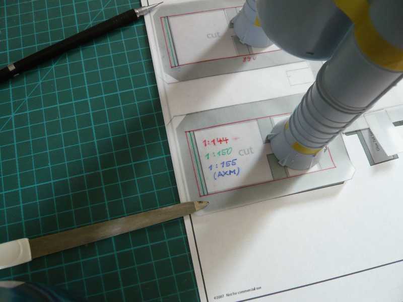
I’ve been thinking about the possible variants of the adaptation of the SRB holes in an emergency surgery.  Here, I will probably widen the SRB holes on 1:144, and adjust the length in a tolerable level, possibly to 1:150 … 1:155 …
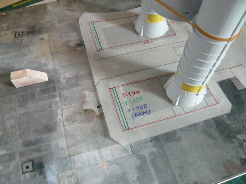
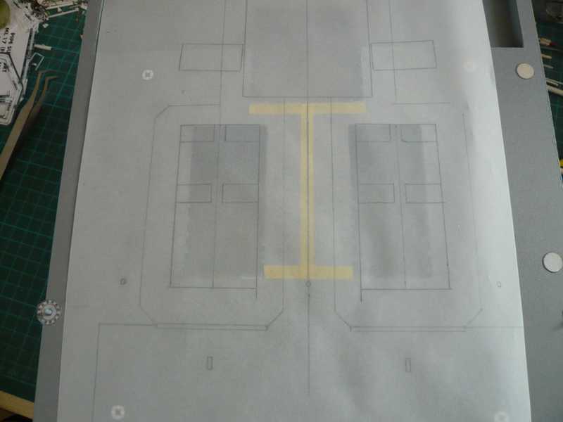
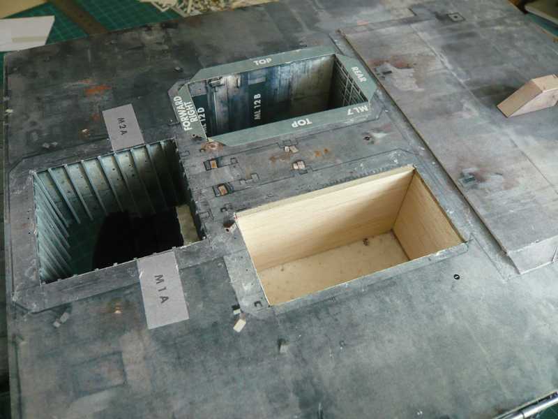
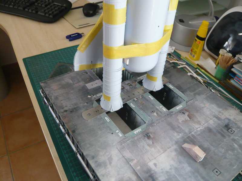
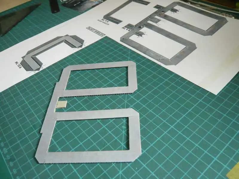
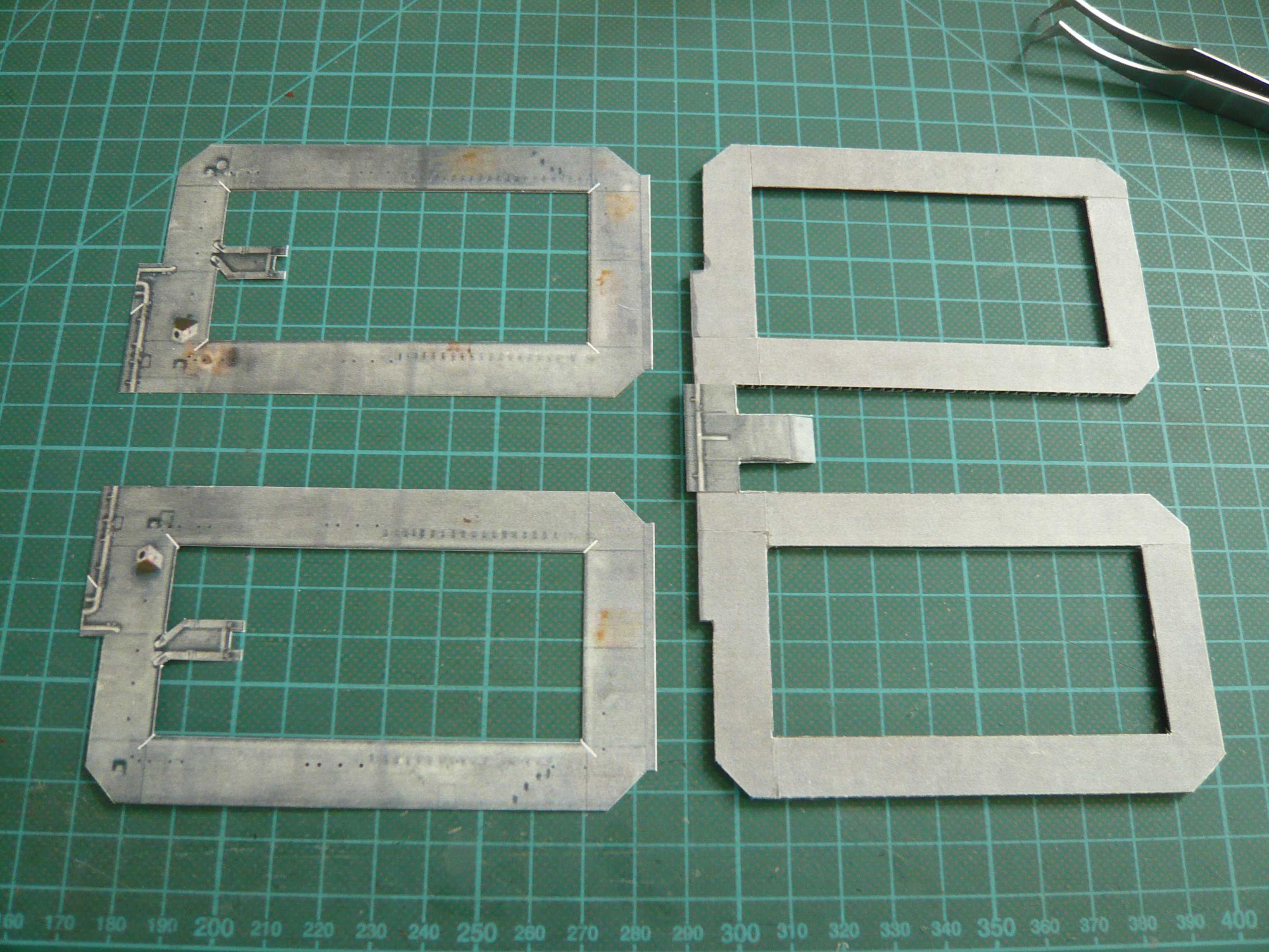
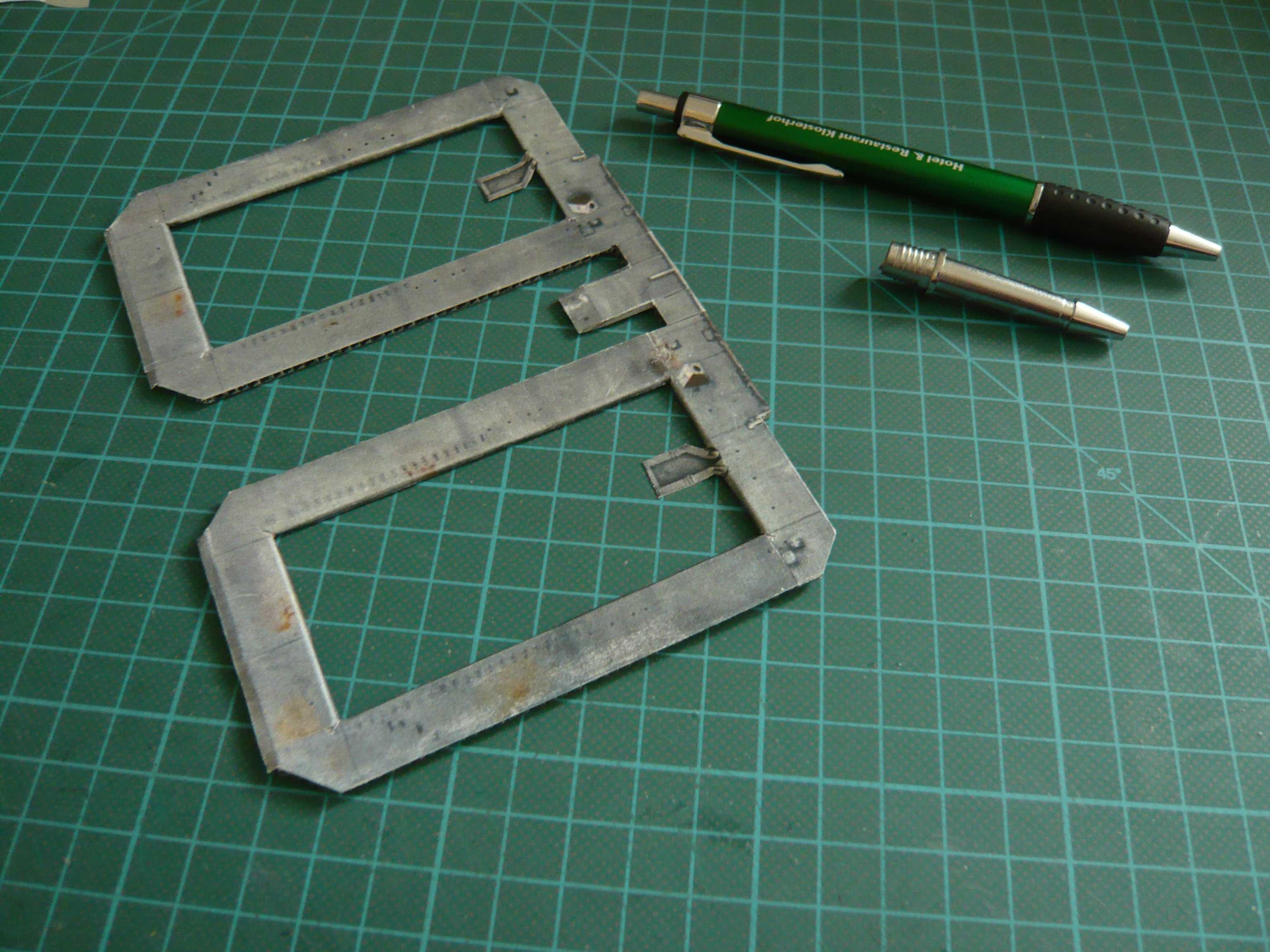
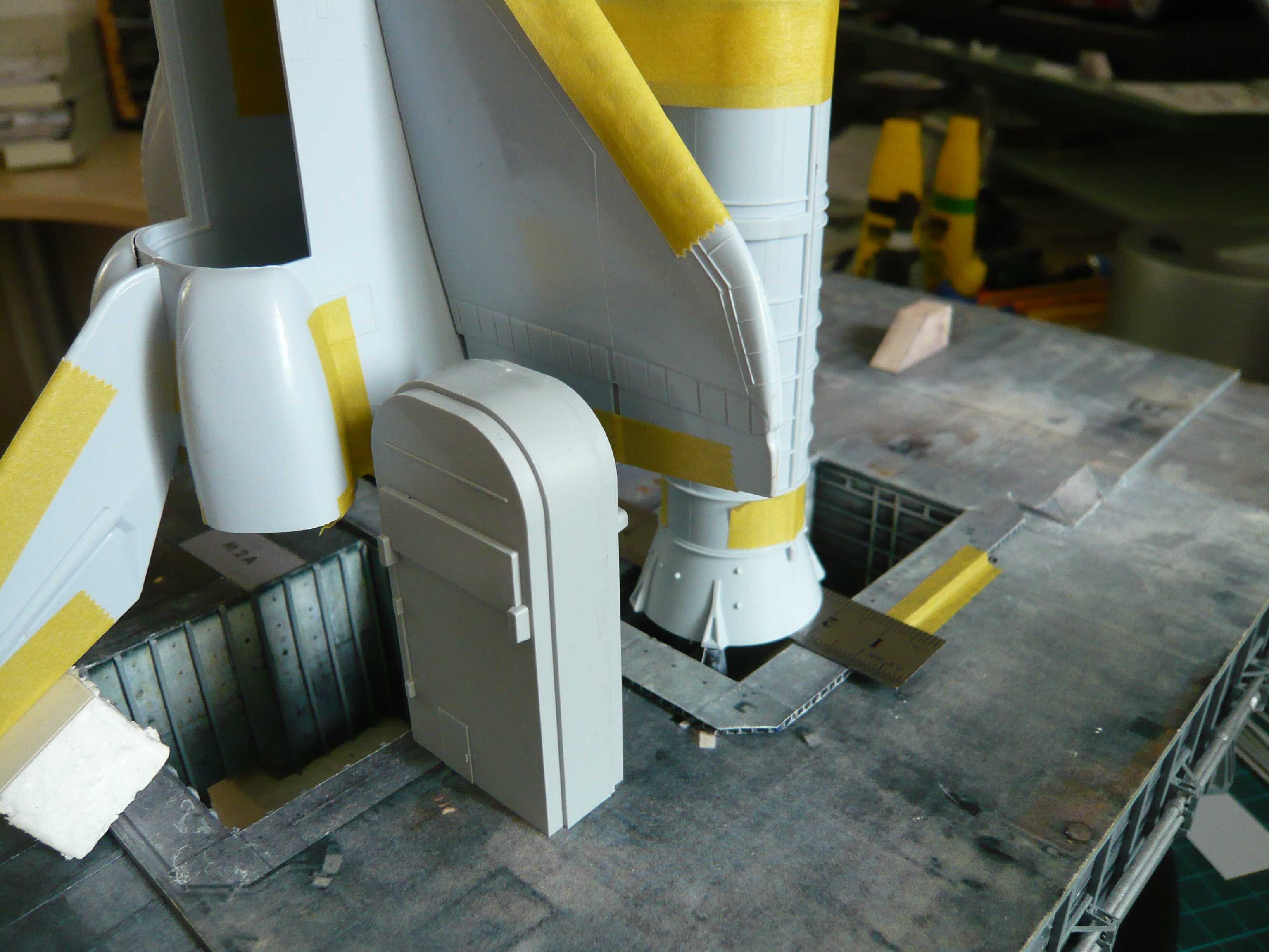
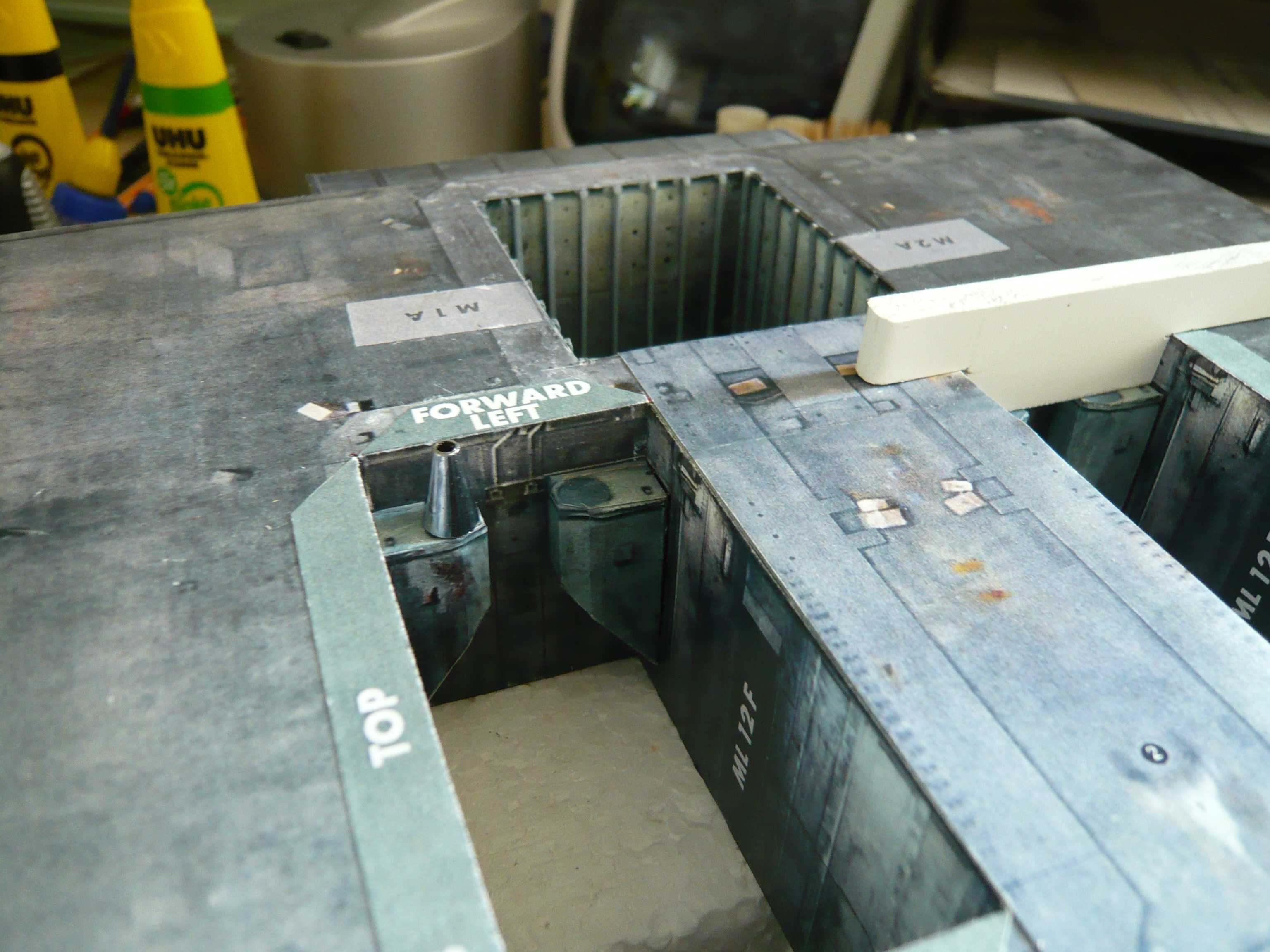
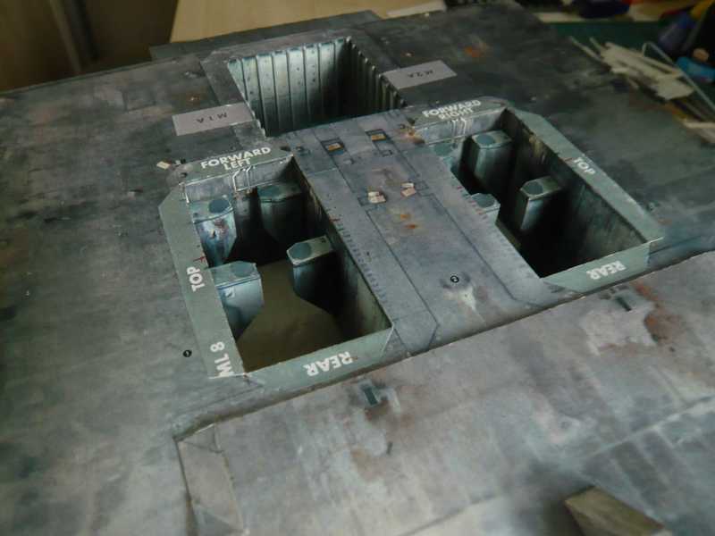
Here are two photos, first on the AXM template,
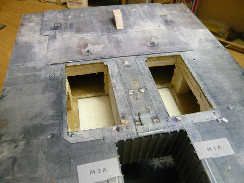
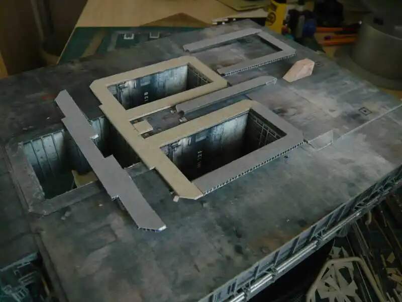
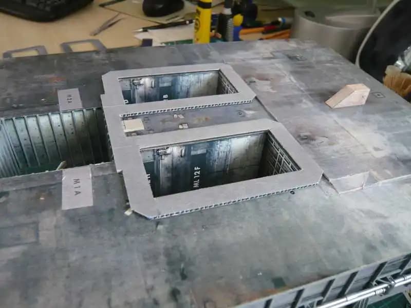
and here on the MLP.
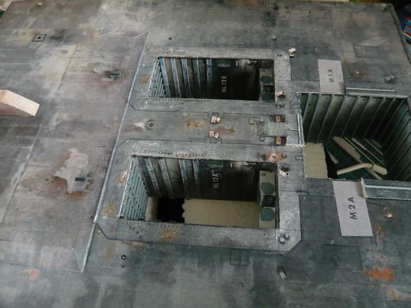
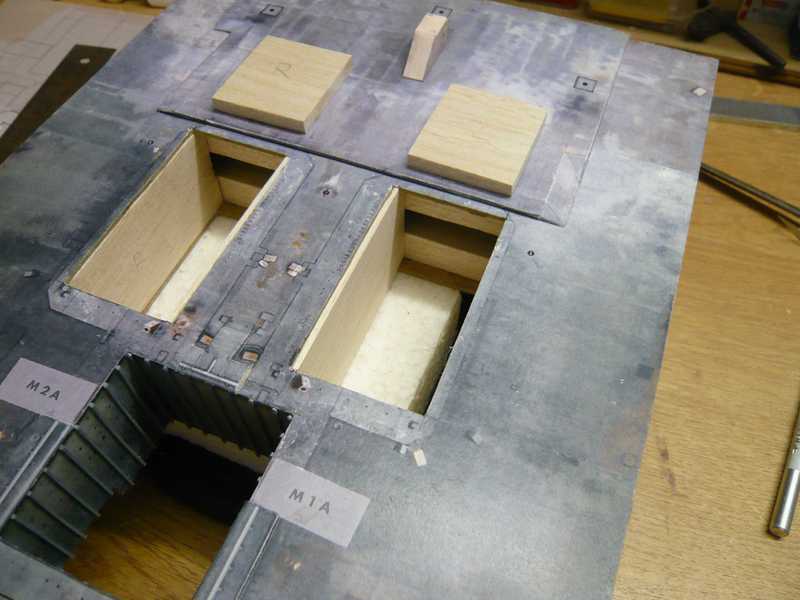
In a first surgery I’ve removed the middle four Hold down posts in the SRB holes what was relatively harmless. The other four on the front walls stick fixed, be replaced also.
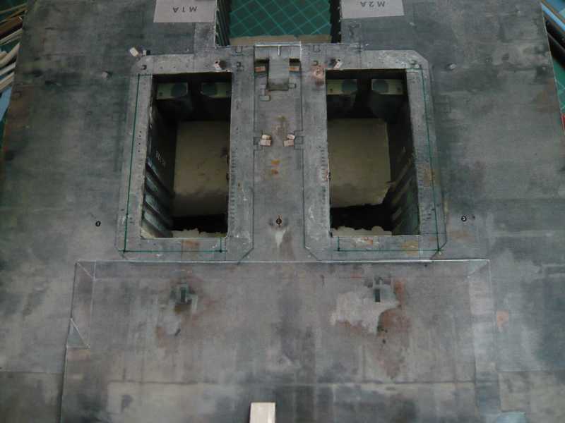
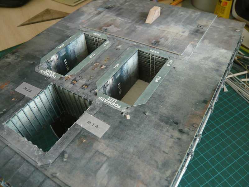
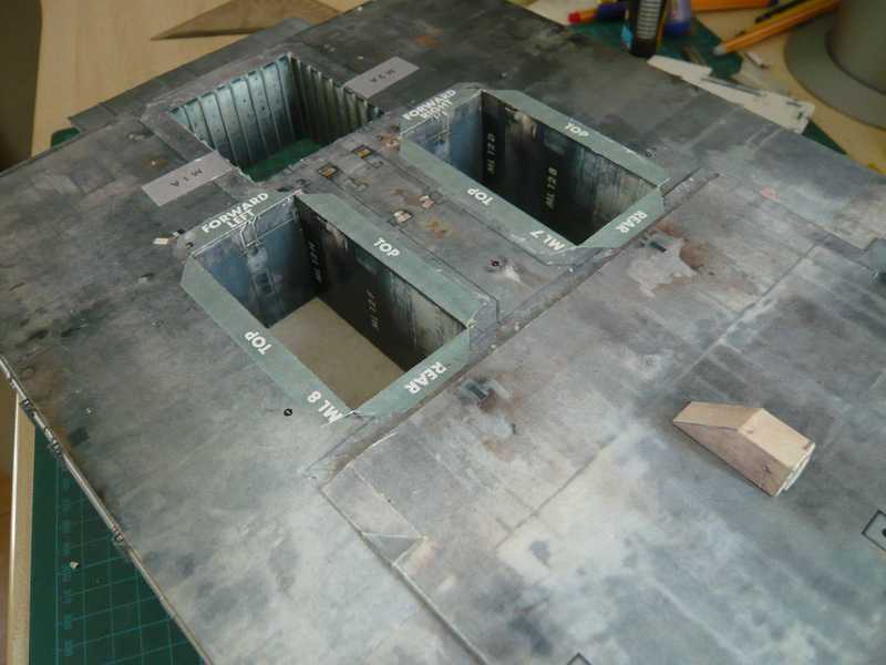
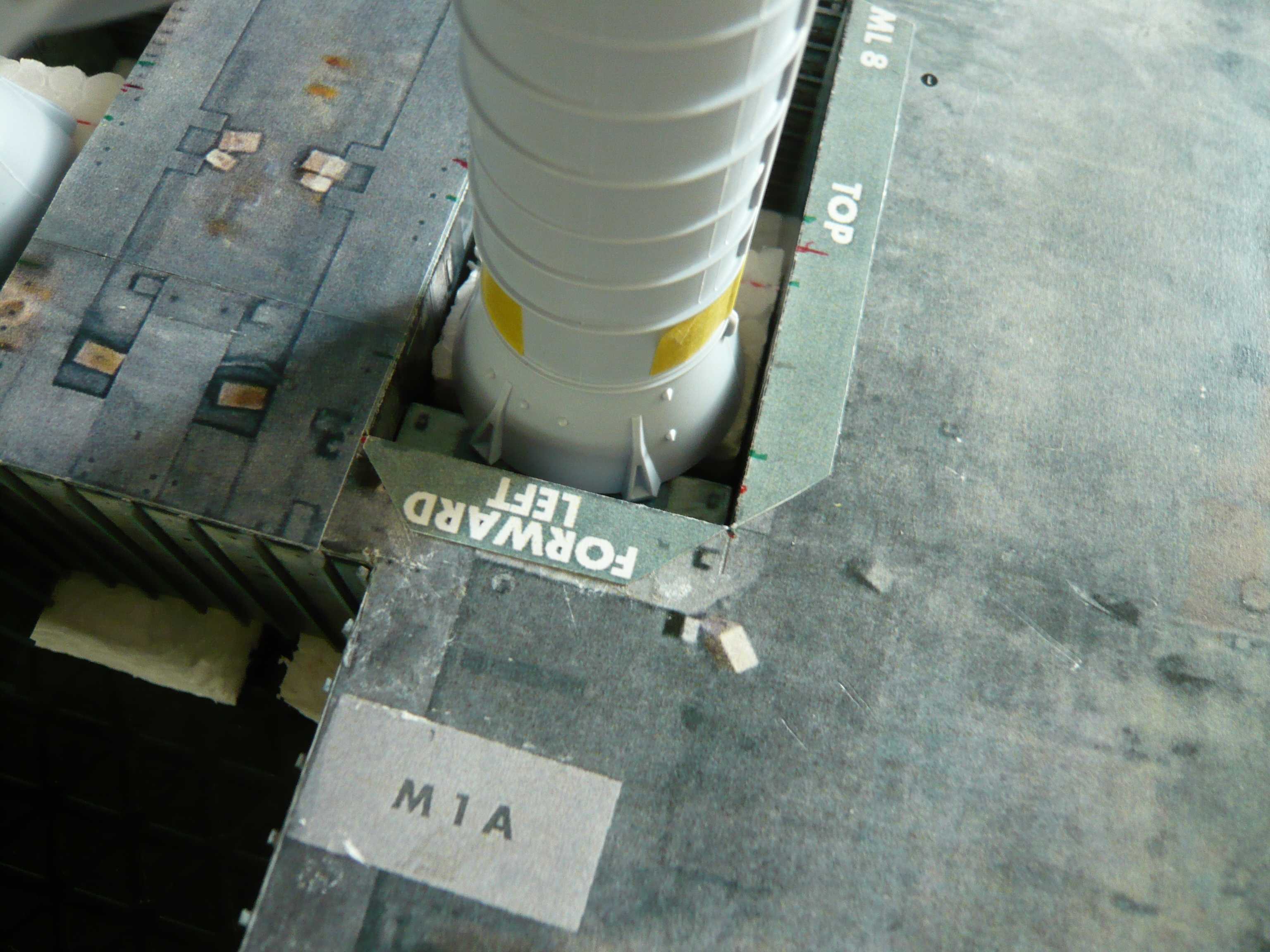
After that I did the SRB-Blast shields piece by piece carefully until the TSMs dissolved and removed, which also still relatively good went to, and then looks like:
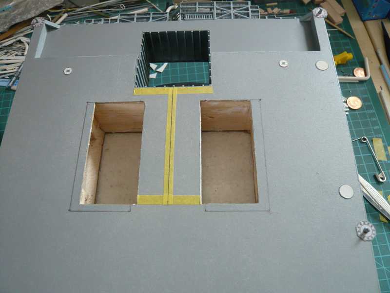
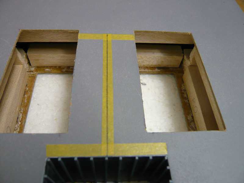
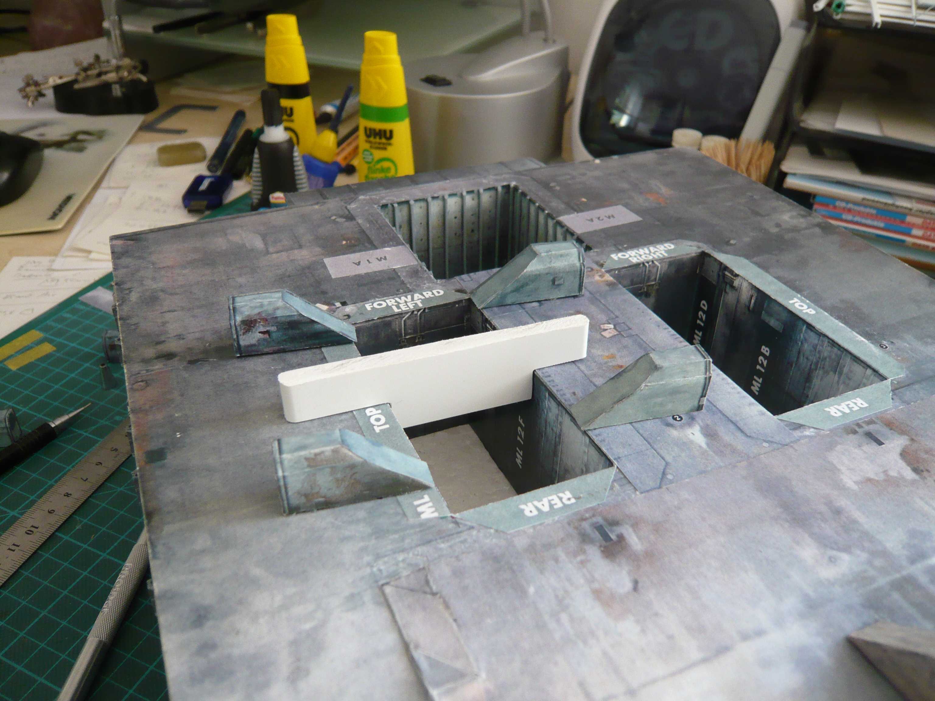
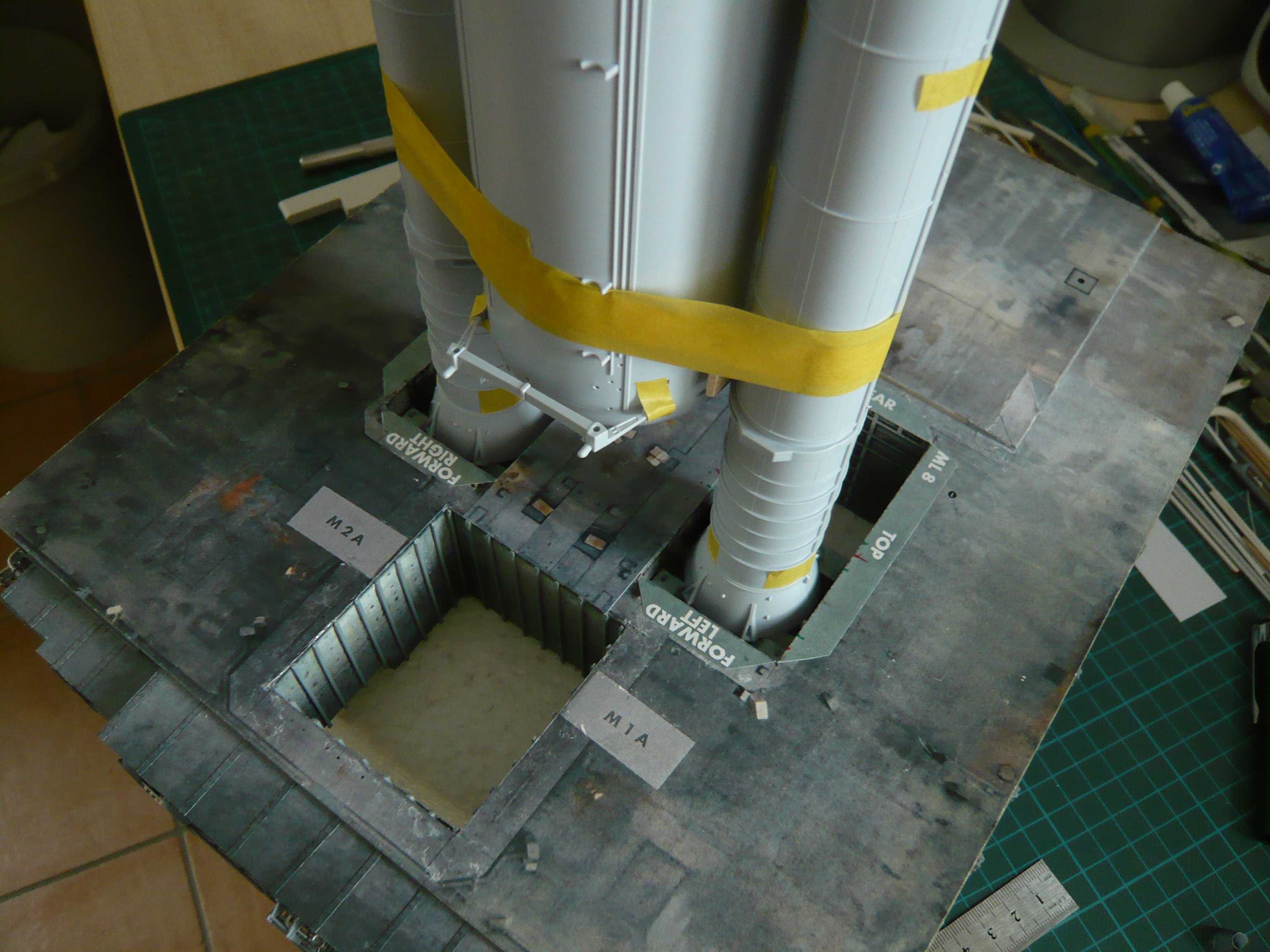
In the meantime I have chosen as well as for the modification of the SRB holes, i.e. with the width I’ll go on the 1:144 level, and with the length to 1:150, which corresponds to the green line. So the Blast shields would go about 10 mm beyond the Blast deck, why I must move the deck this 10 mm backwards.
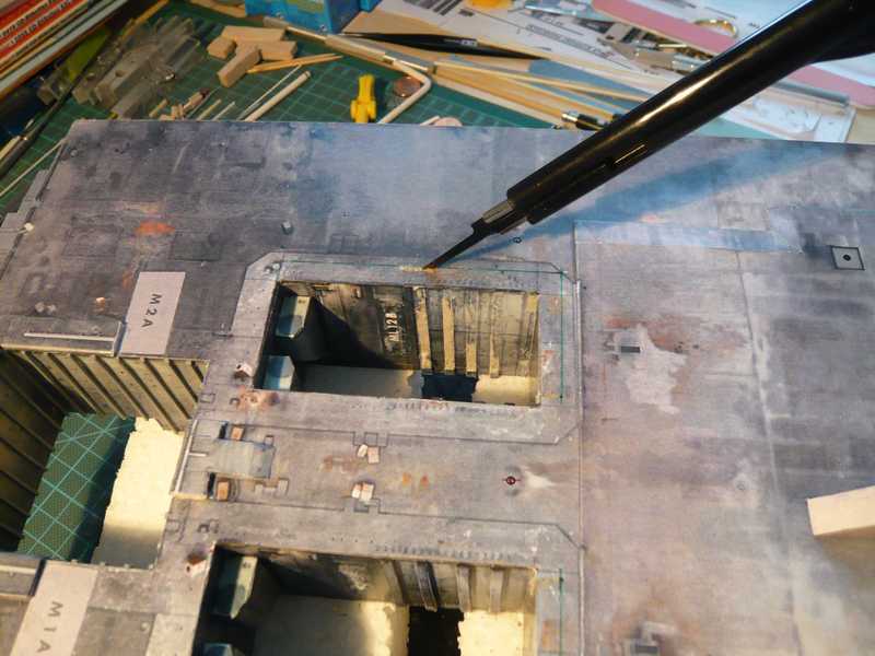
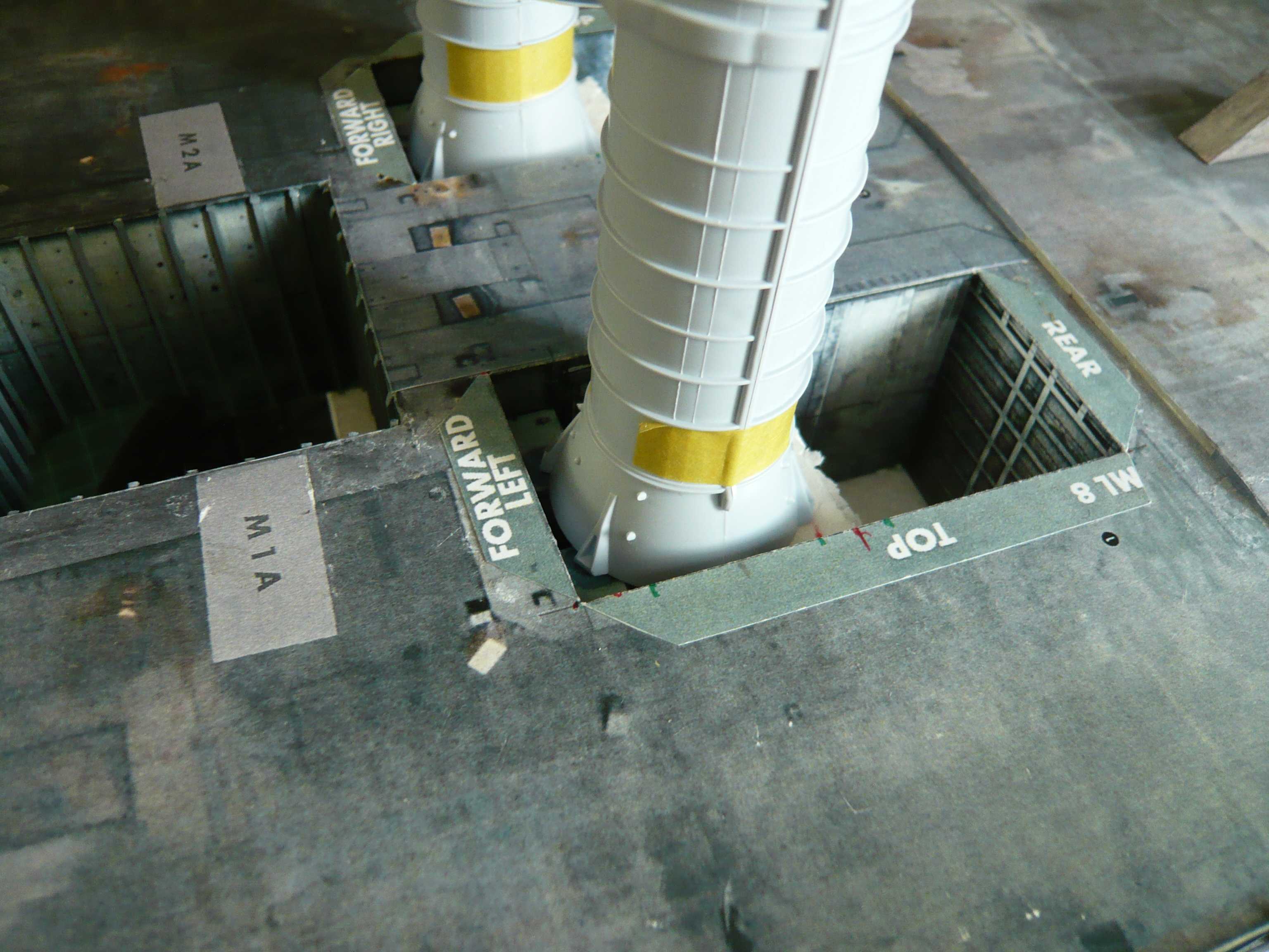
To create this space, I’ll probably cut the blast deck along the line with the red arrows, and put back the front part. Thus the two Rain birds (green arrows) to this small move while piece next to rear, what but to get over, and the Blast shields back flush with the Blast deck off.
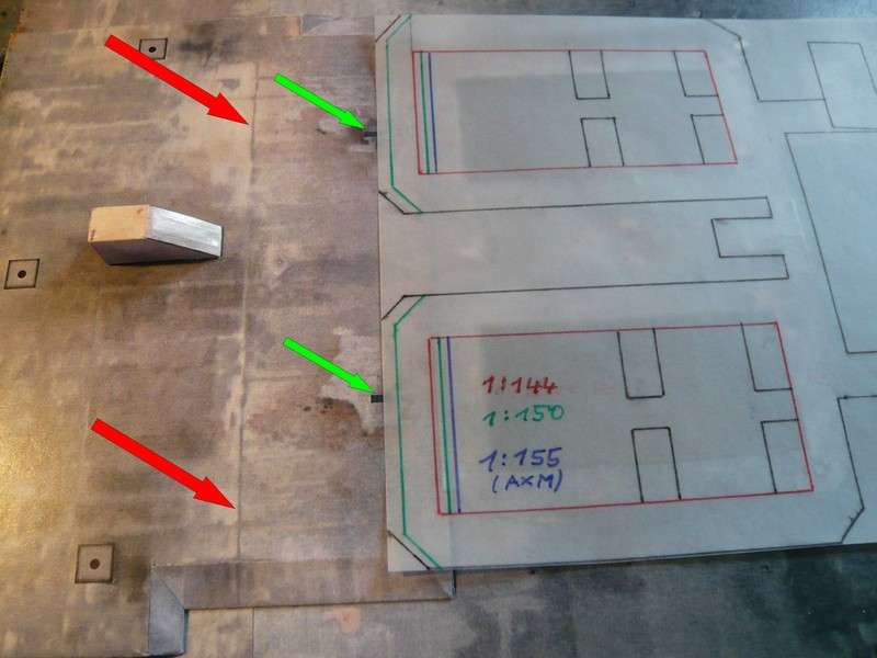
And so the stack would then sit across the SRB holes, what actually made quite well together and would have to fit the proportions, and thus would be even enough space for the SSWS pipes and Water bags. ![]()

So far for today, next time the deeper cuts will follow … ![]()
2 Likes
Hello everybody,
I’ve decided yet different and I’ll go to 1:155! ![]()
And now guys it goes right to the thing, I only have to think about just the right battle plan where and how I best start and with which tools. ![]()
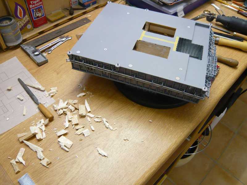
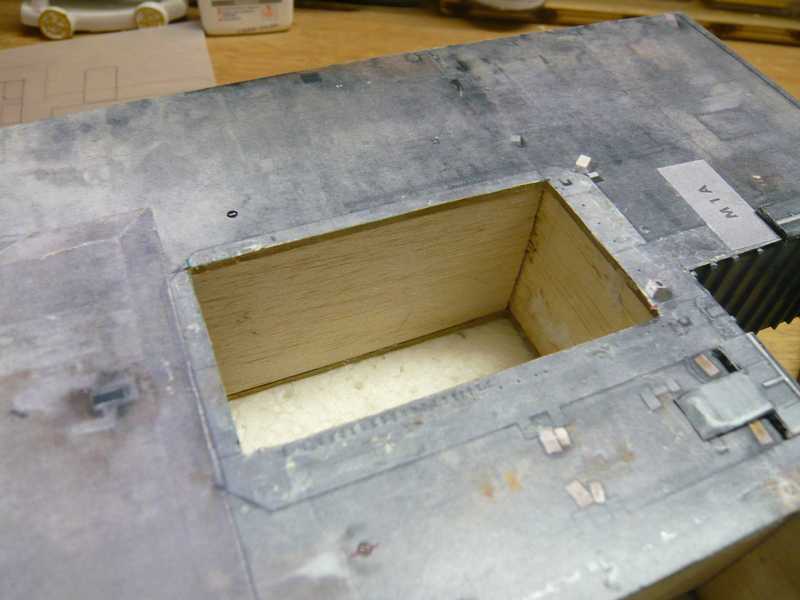
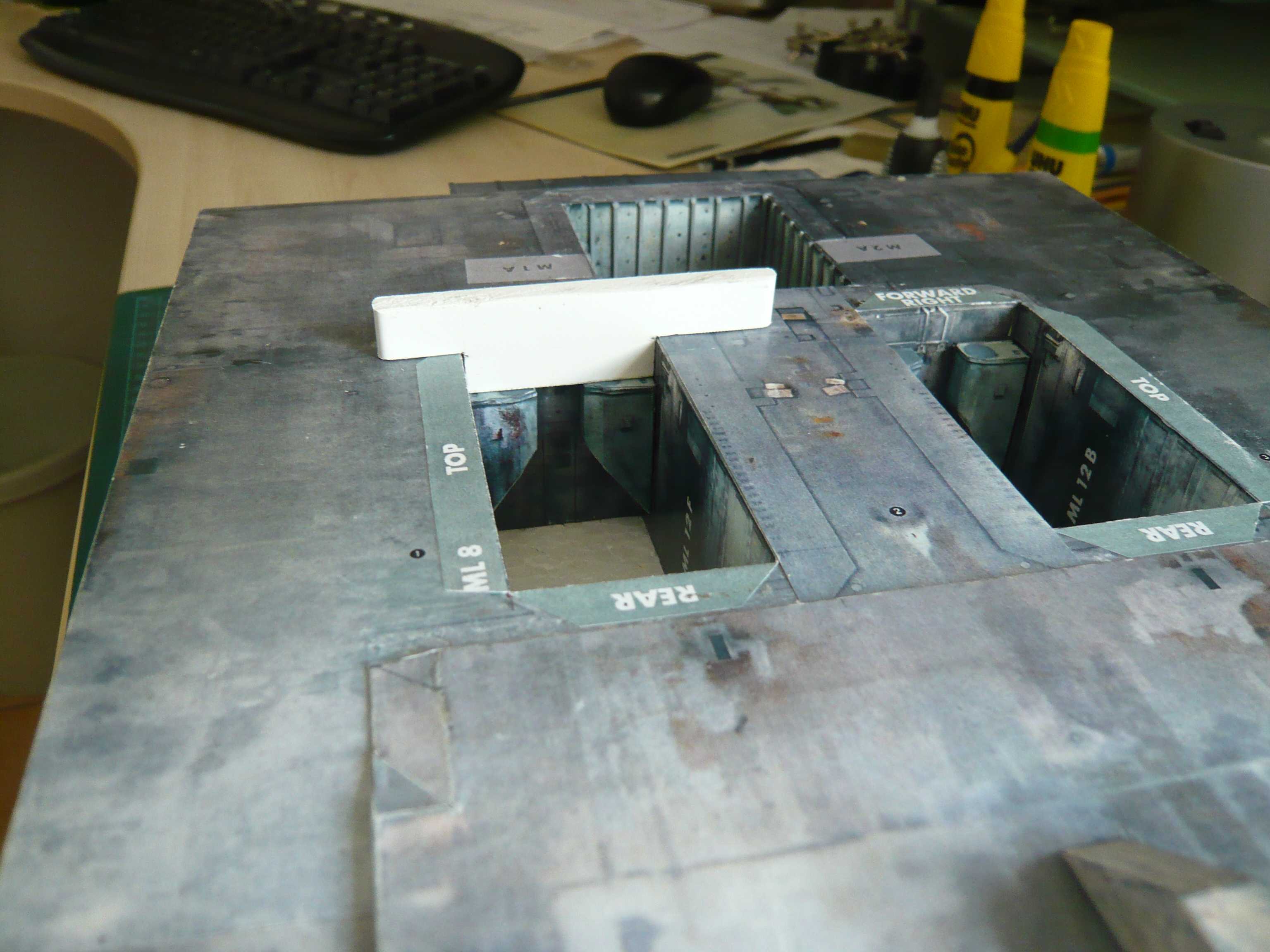
To do this I must look again at my old photos from the start-up phase, as I had built the substructure. Then I know roughly where I come out with my cuts through the hardboard either/hopefully in the cavity, or in the Balsa wood.
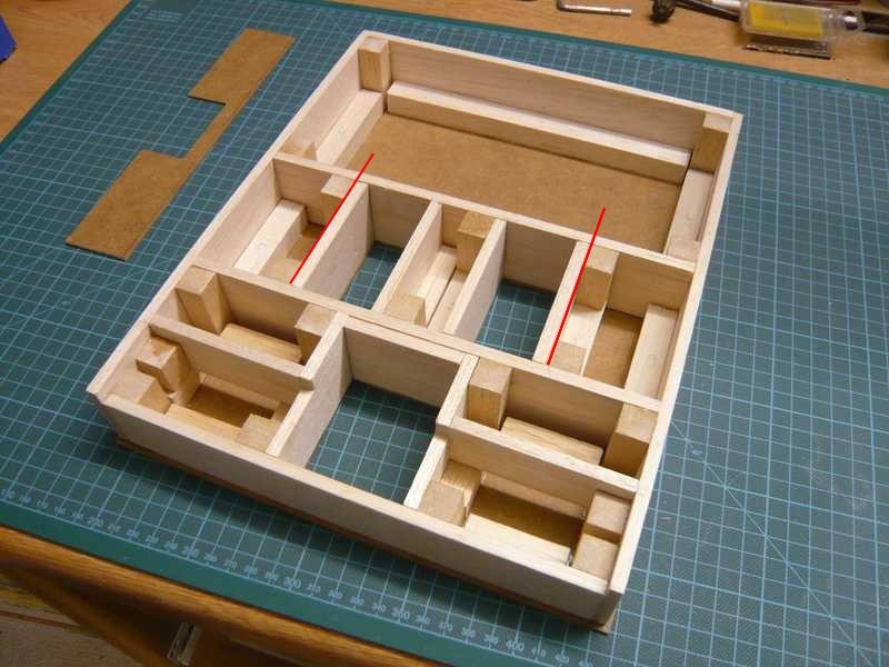
The cut line of the long sides will be probably right behind the inner shaft wall. As a result, the rear wall will need also away. ![]()
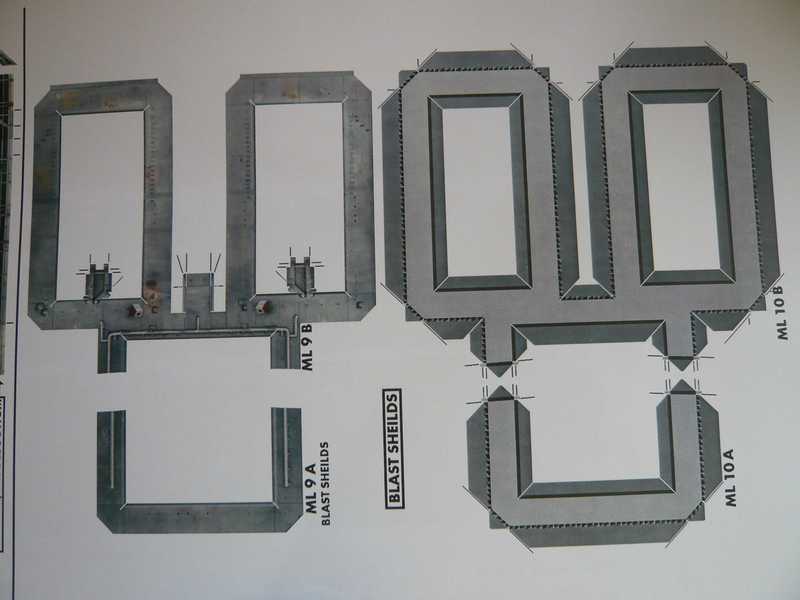
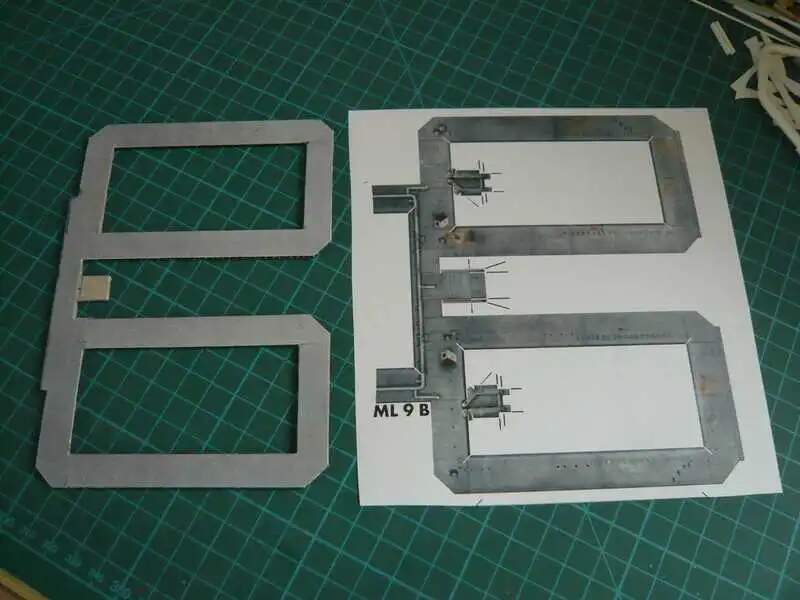
And here is the drawing for the modified SRB.
Firstly, I’ve tried carefully a few cuts with the mini saw,
and then drilled a few holes for the saw to come through the upper hardboard.
The sawing but not particularly went well, maybe I came out even in the side wall which saw stuck in more often and which has repeatedly jammed. That’s why I took up then the Dremel,
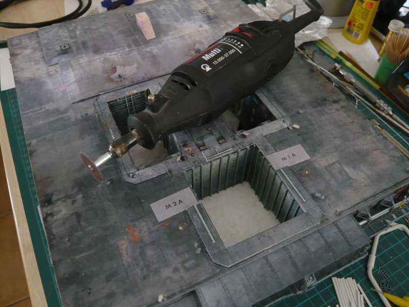
and with the blade the hardboard through scratched up on the Balsa wood.
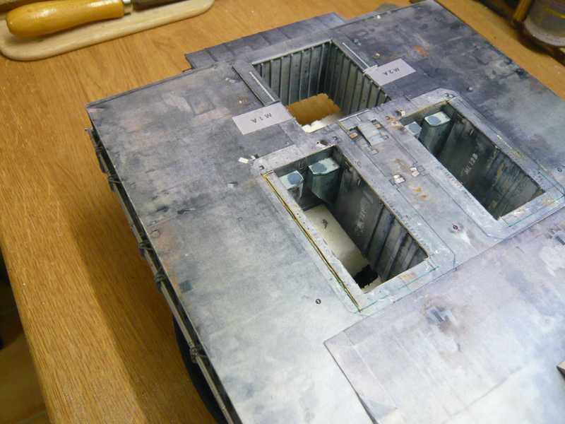
And then it painstakingly went piece by piece with saws, chisels and cutters in depth, ![]() and that hurt me in the soul and is genuine to the howling …
and that hurt me in the soul and is genuine to the howling … ![]()
This was overall quite stressful, but there also no whining helps.
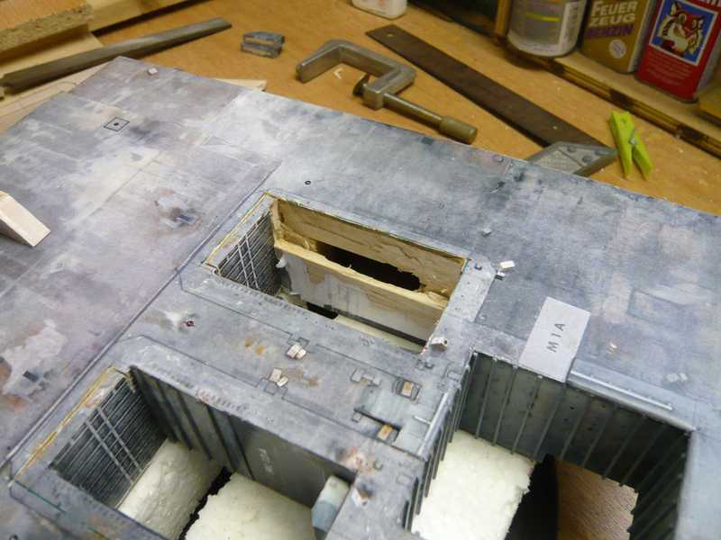
Finally, I have cannibalized both shafts up to the lower hardboard in the truest sense of the word, ![]()
and can draw the bottom hardboard for the cuts now.
Now gotta only strongly take a deep breath … ![]()
Surely every model-maker’s nightmare come to life – switching scales mid-project, Holy Reductions. I can only look through one peeking eye & admire your bravery & surgical skills ![]()
![]()
![]()
wow … a re-scale … that sounds very daunting and would scare the hell out of me !!! How does that effect the kits and their scaling against the launch platforms ?
Thanks Martin for your compassion. ![]()
But what has to be, has to be, it’s all a consequence of the dilemma of scale. The Shuttle Stack with its boosters inevitably needs its place on the MLP deck. ![]()
The only thing that helps is clenching your teeth, closing your eyes and through! ![]()
1 Like
Yep, John, as I said to Dioramartin already, that doesn’t matter. Some adjustments will probably still be necessary. ![]()
But where there’s a will, there’s a way. ![]()
1 Like
Hello everybody,
but first, I had to insert a break to gain some distance and to take new courage. ![]()
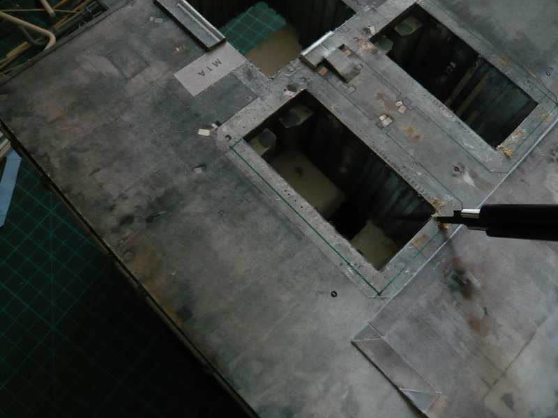
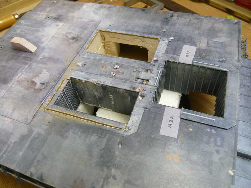
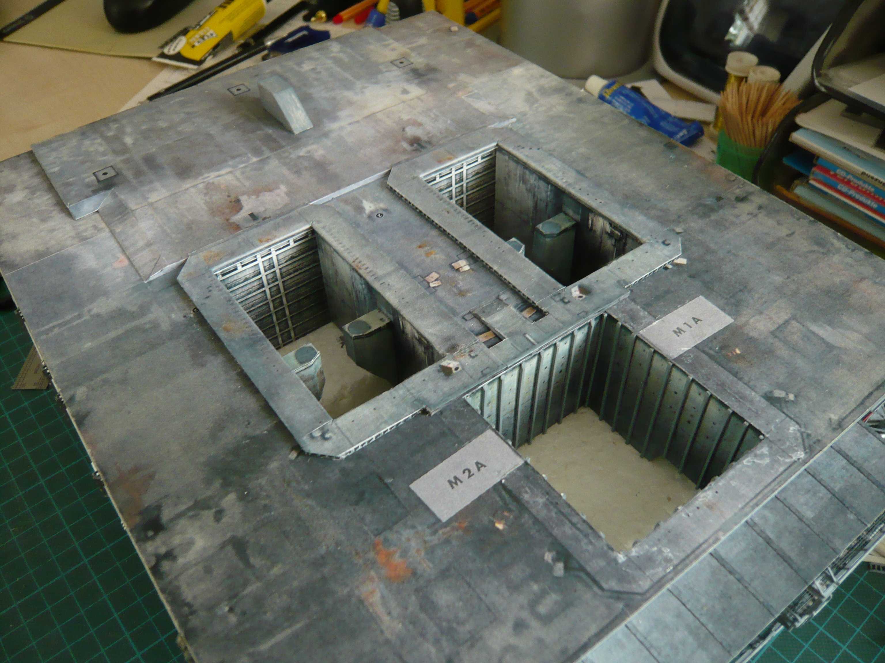
And further went to draw the new contours of the SRB hole openings on the hardboard on the bottom,
that I sawed out with the Mini saw.
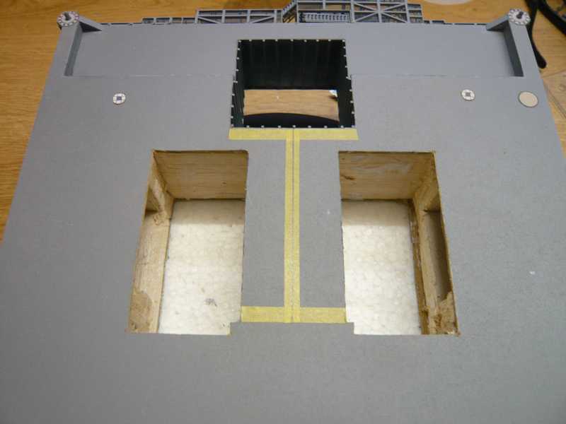
Back flush with the shaft holes to insert the outer walls of the shafts, only remnants of the side support bars had to be removed. That was a pretty tedious action where there was lots of shavings and dust. ![]()
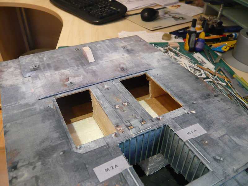
But then, it was finally done. 
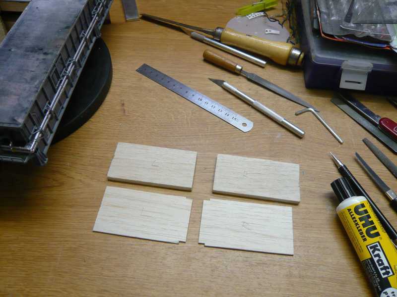
For a stable fit of the outer walls, I have again prepared supports of Balsa piece 15x15 mm and fit.
The side walls are again from 6 mm Balsa and fit quite well into the openings.
Now the parts must be glued only. The rear walls are then prepared in a similar way and inserted, bringing the shafts again slowly take shape. ![]()
Keep on knocking on wood! So far everything went well, so go on. ![]()
1 Like
Very impressive. ![]()
I am assuming others are seeing these photographs in your recent posts as they are commenting positively. However, I am still having trouble seeing them. Hopefully, that will change soon.
In the mean time, keep it coming my friend!
1 Like
Thanks Mike,
yep, it really hurt, but fortunately it was fixable, as I’ll show soon. ![]()
Hello everybody,
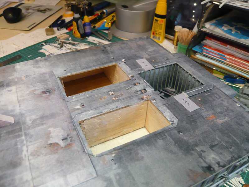
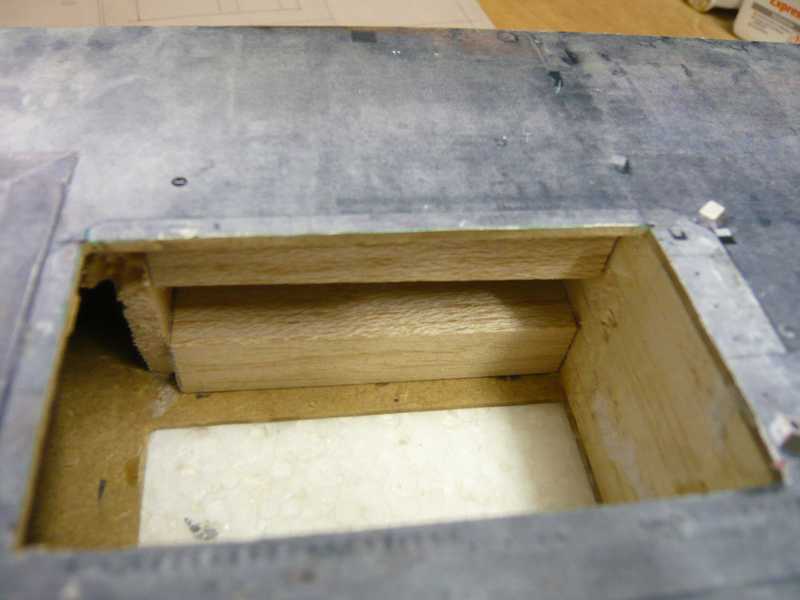
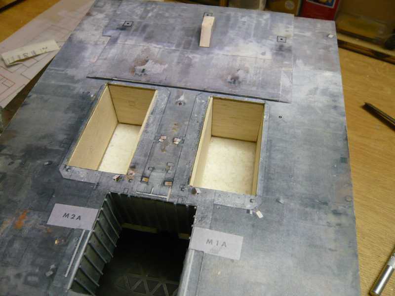
here you can follow the further lining of the SRB Blast Chambers using Balsa parts.
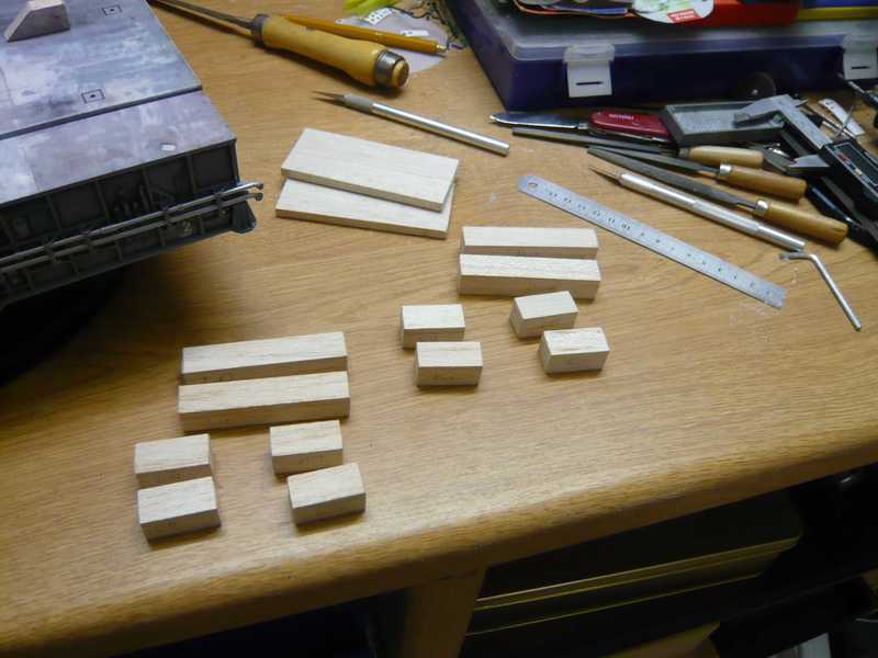
And here are some new pics from the site. These are the squared timbers for the support of the outer side walls,

they then together with the supports for the back walls were glued.
Then the side panels could be glued,
missing only the covers for backs.
And after that are finally glued, but everything looks already once again much more friendly, isn’t it?
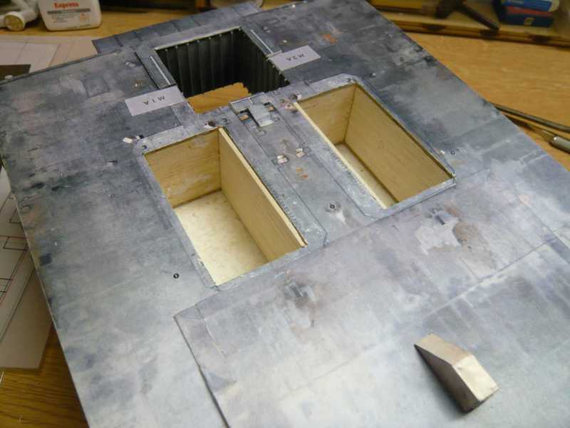
After smaller filling works with putty the SRB Blast Chambers could now be repapered. It’s a good thing that I still have the 1:144 original templates from the paper kit.
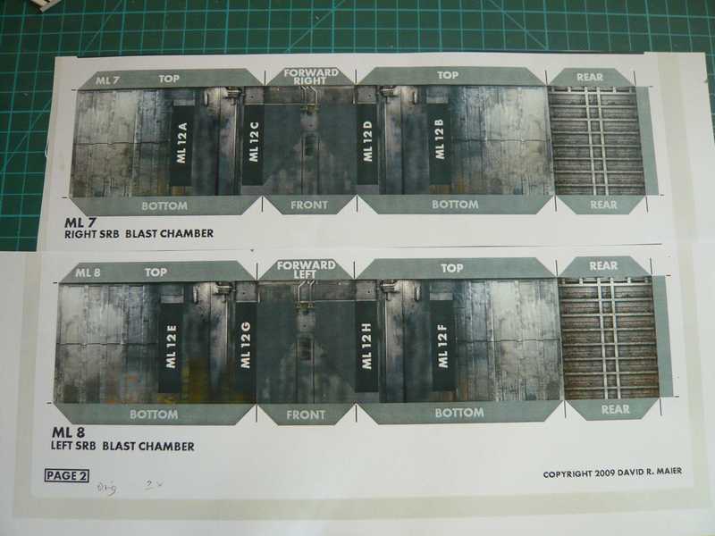
The side walls had to be cut while the modified length and the height be reduced,
otherwise the re-wallpapering was not rocket science. ![]()
And so I already feel much better like. 
Next the Blast shields have to be installed,
and the Hold down posts I can use again, I guess. ![]()
Oh well, so slowly uphill again! ![]()
4 Likes
Hello everybody,
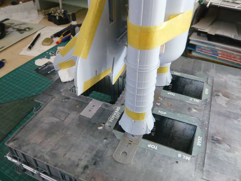
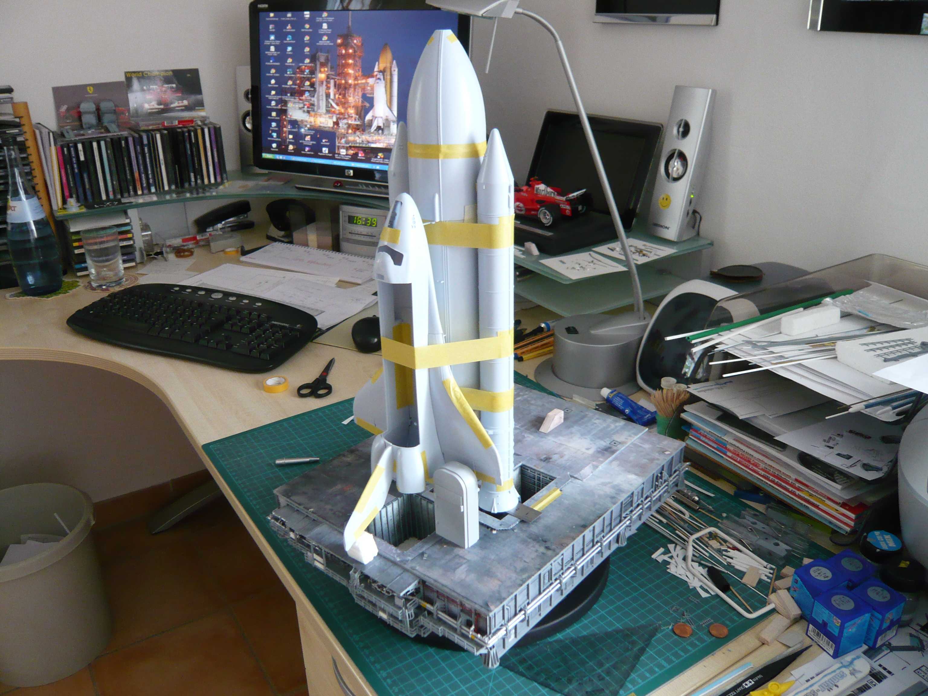
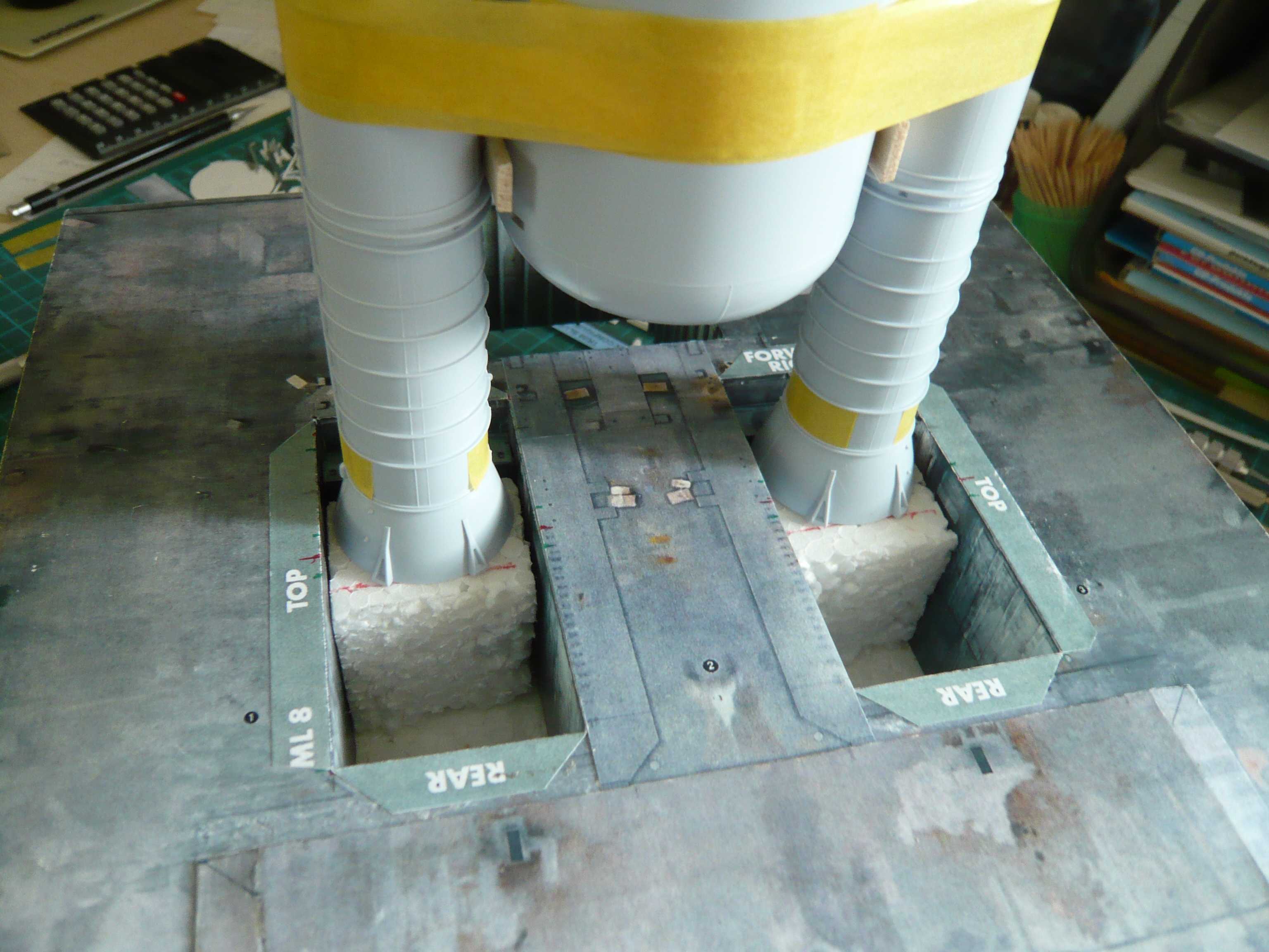
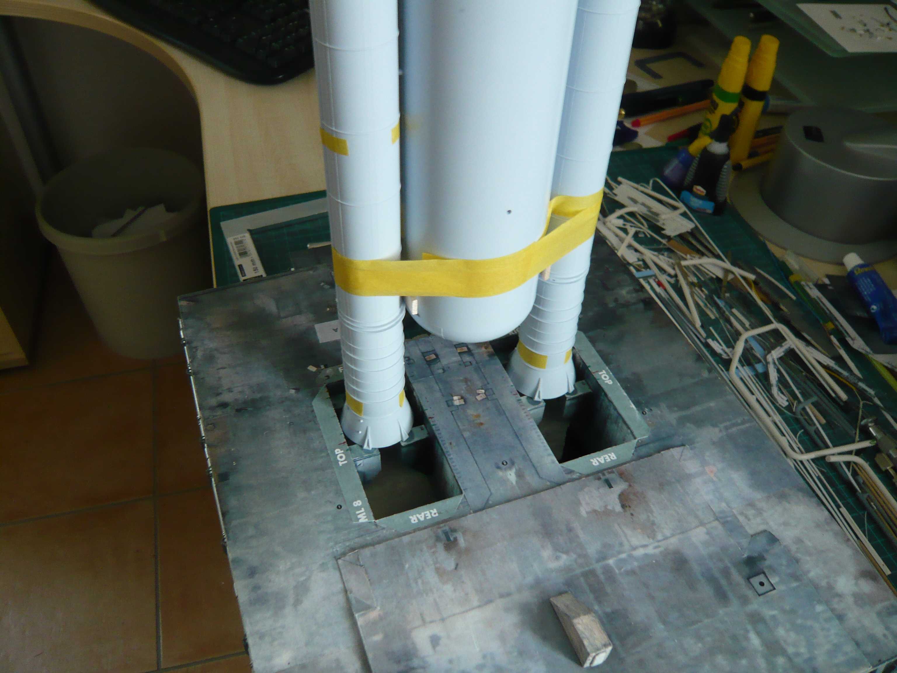
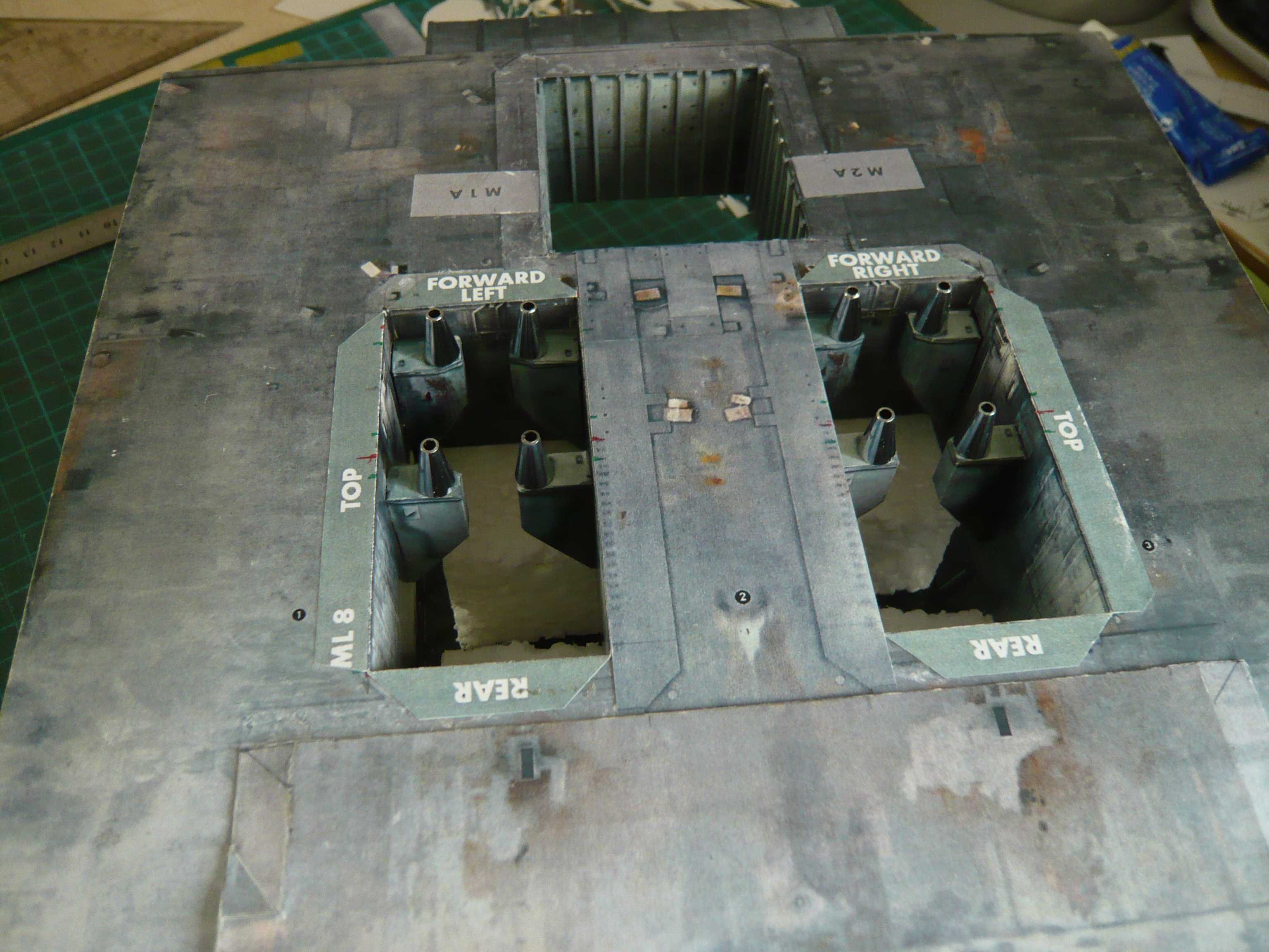
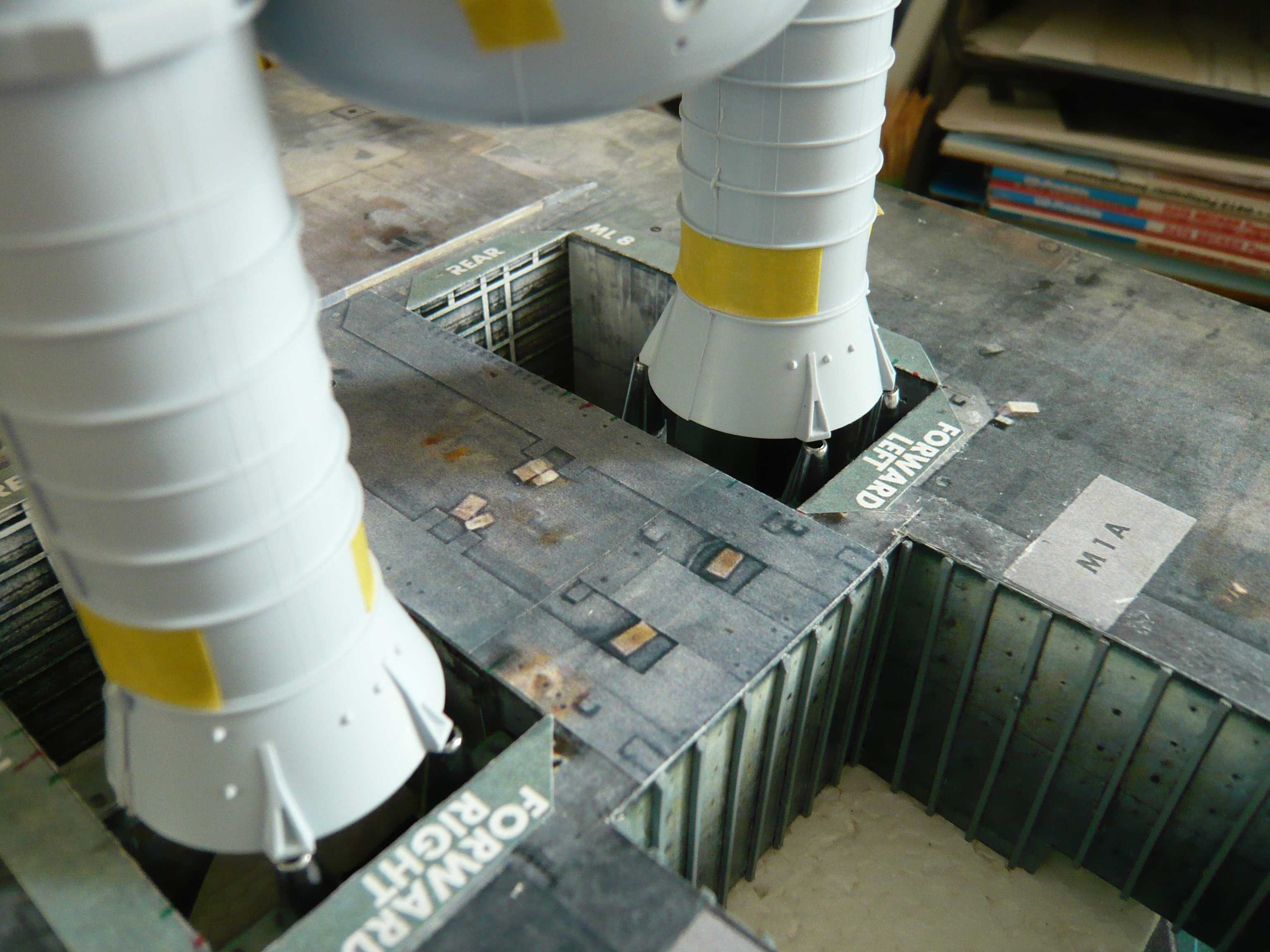
after rebuilding of the SRB Blast Chambers I tested now the position of the stack, and I am completely satisfied with the result. The stack is actually perfectly across the width of the SRB holes and is also sufficient space for the SSWS pipes.
That’s why I could now again devote the Blast shields. But first I have planned only the SRB-Blast shields. The SSME-Blast shield I will install only after completion of the SRB-Blast shields and the final installation of the Hold down posts, when I know exactly where the TSM’s ultimate will stand next to the orbiter. Therefore, at the substructure of the SRB-blast shields I’ve omitted the approaches of the SSME-Blast shields that later reset. For the substructure I used 1,5 mm strong cardboard.

For the coverage of the substructure I had to customize the 1:144-template according to my modified geometry, which is why I have divided it into several parts.
That was something difficult with folds set to on the sides,
but after everything was glued the part looked quite well and fit well so that it can be glued tomorrow. This is followed by then gluing the top coverage, which I must customize in the same way and have to divide.
As I’ve said, the SSME-Blast shield remains only aside.
Slowly but surely things are moving forward and fortunately the worst is over …![]()
3 Likes
You can definitely see the difference… Well worth the effort ![]()
Yep John - No pain no gain! ![]()
Hello everybody,
next the covers were to suit according to the modified blast shield base, divided and then glued.
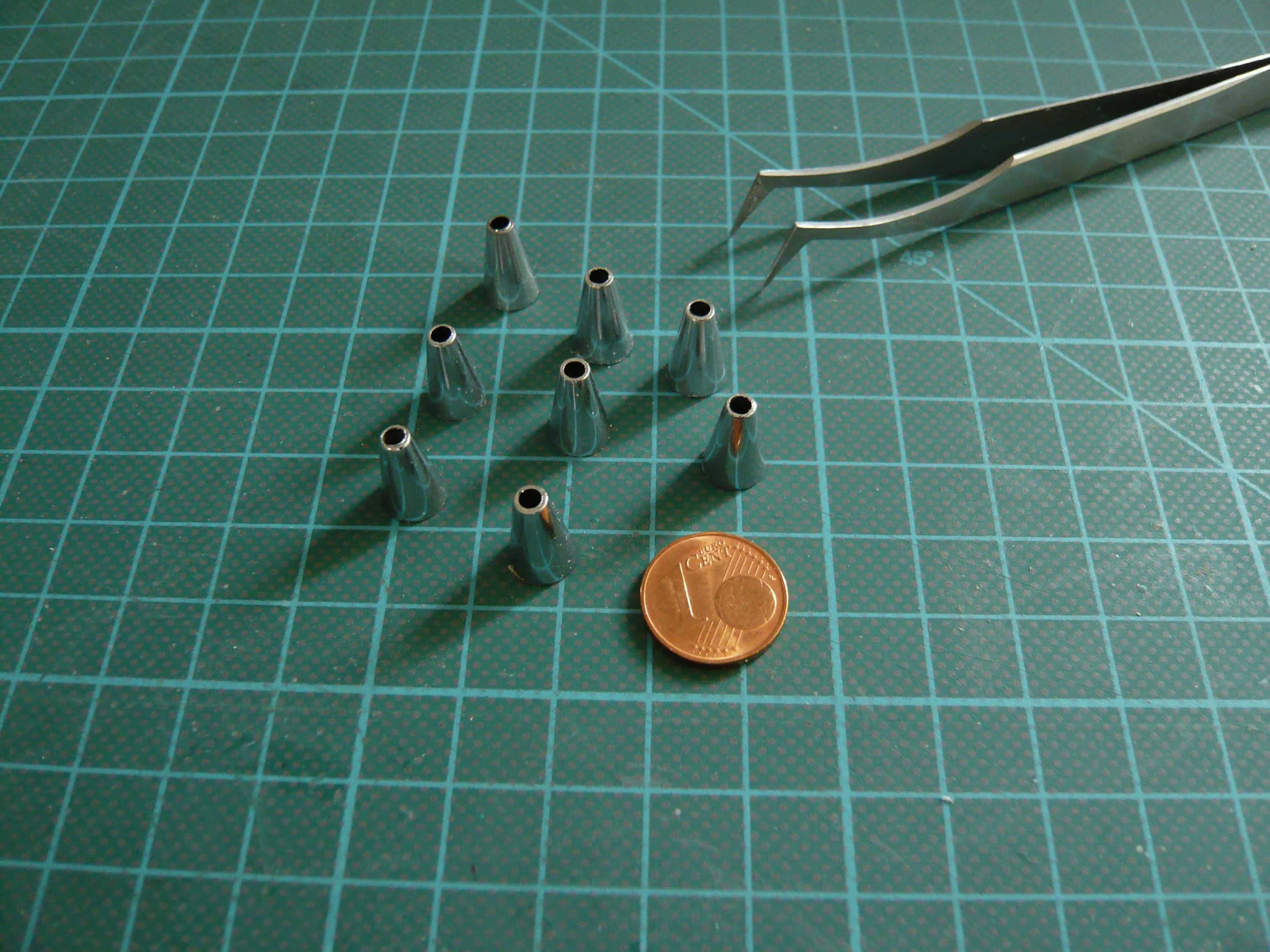
In order to determine the correct height for the Hold down posts in the holes, I glued times one of the four cones, which sits on the top of the Hold down supports and are screwed with the SRB aft skirt keeping the entire stack.
While sitting the rear two screw connections under these red caps,
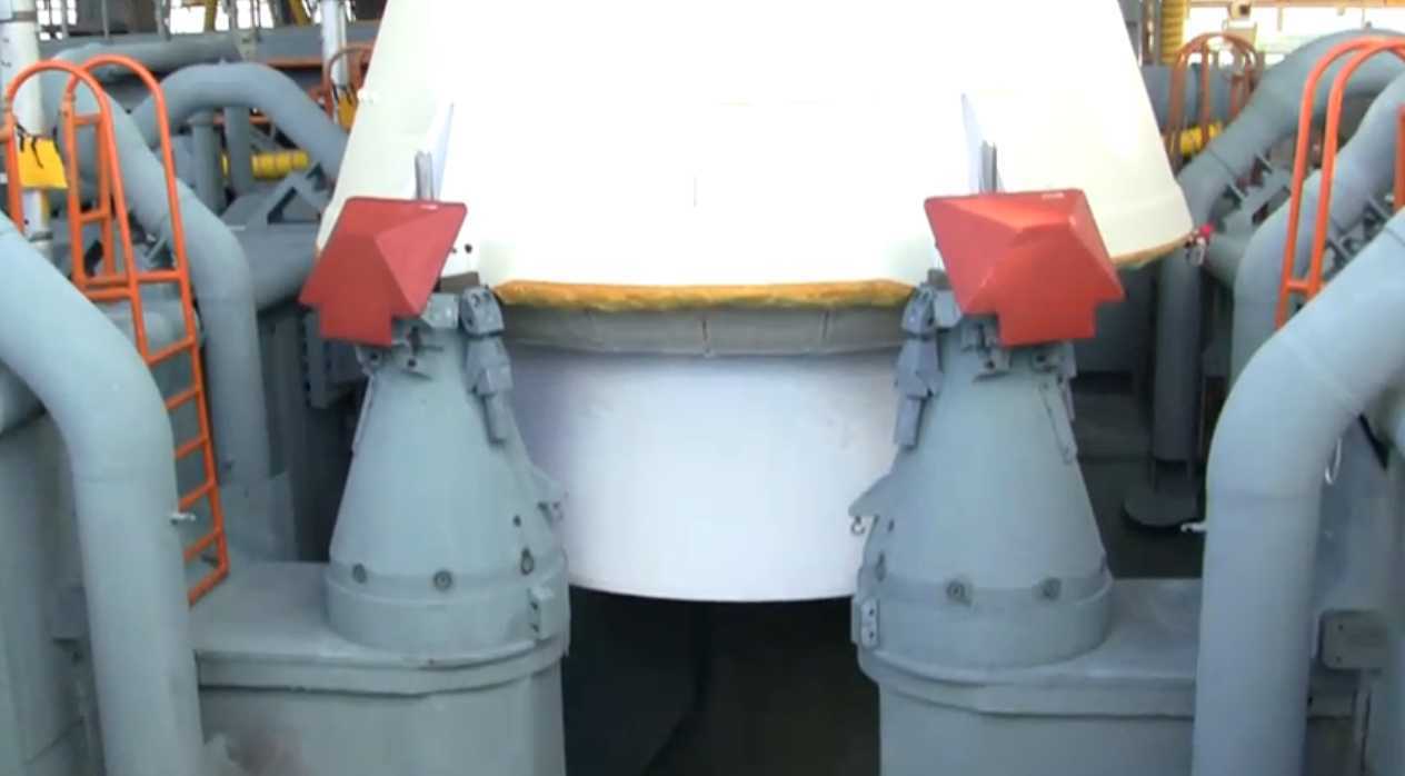
Source: NASA
missing these caps on the front screw connections.
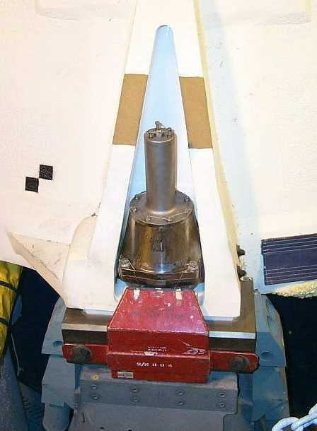
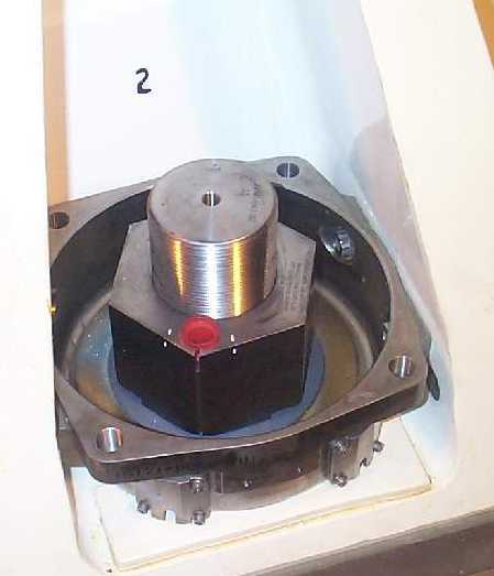
Source: NASA
During Lift-off, the nuts of these four screw connections on both SRBs are blown off simultaneously by explosive charges (below the red dot), thus releasing the Shuttle stack.
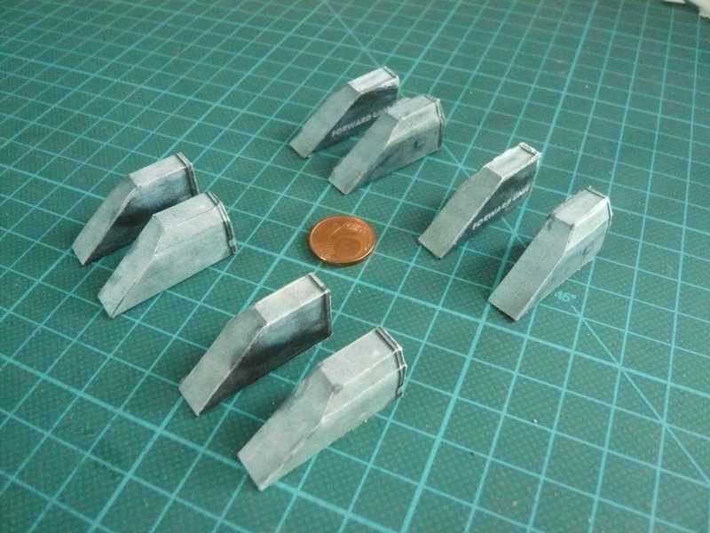
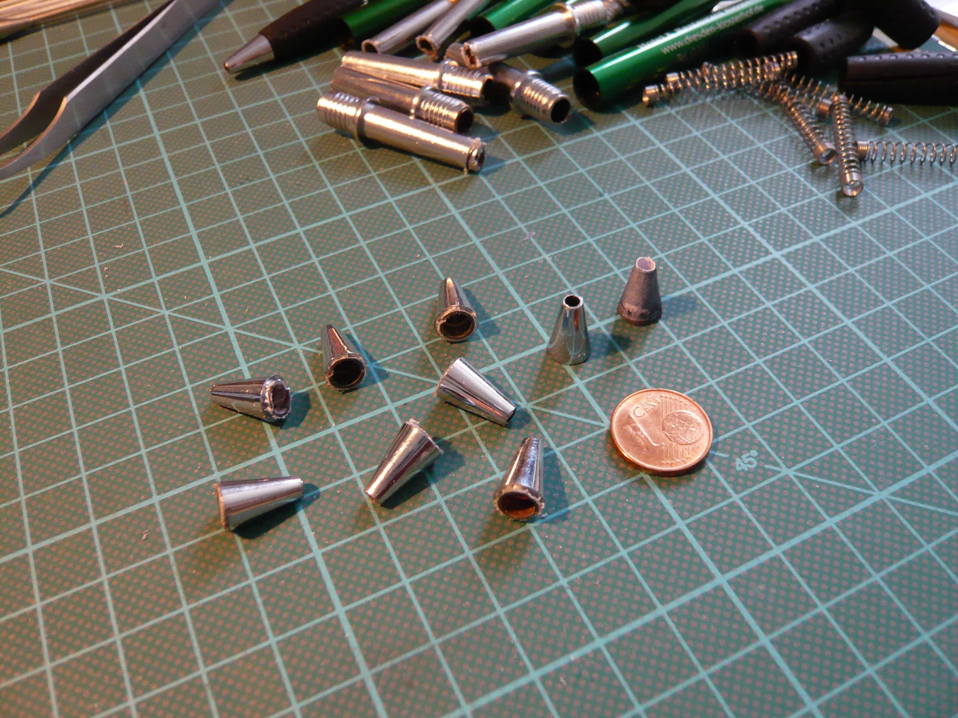
On this image one of the cone from the paper kit is to see that my opinion but would be too weak without amplification, to stabilize the model stack. Therefore, I will strengthen them through the plastic tip of a ballpoint, that almost have the appropriate dimensions, and of which I have organized eight pieces me. 
With the paper cone on the Hold down support I have made a fitting, that fits quite well both the position and the height.
Now I have only the hold down support again to glue in the holes and then prepare the eight tapered tips for the SRB mounts. Then the SRBs on the aft skirt support points are provided with a small hole, and in the cone top, matching steel pins as “Pin” to the recording are each pasted as a counterpart. And the stack should be on these mounts then sufficiently stable and upright, I hope at least. 
As far as for today. ![]()
3 Likes
Hello friends,
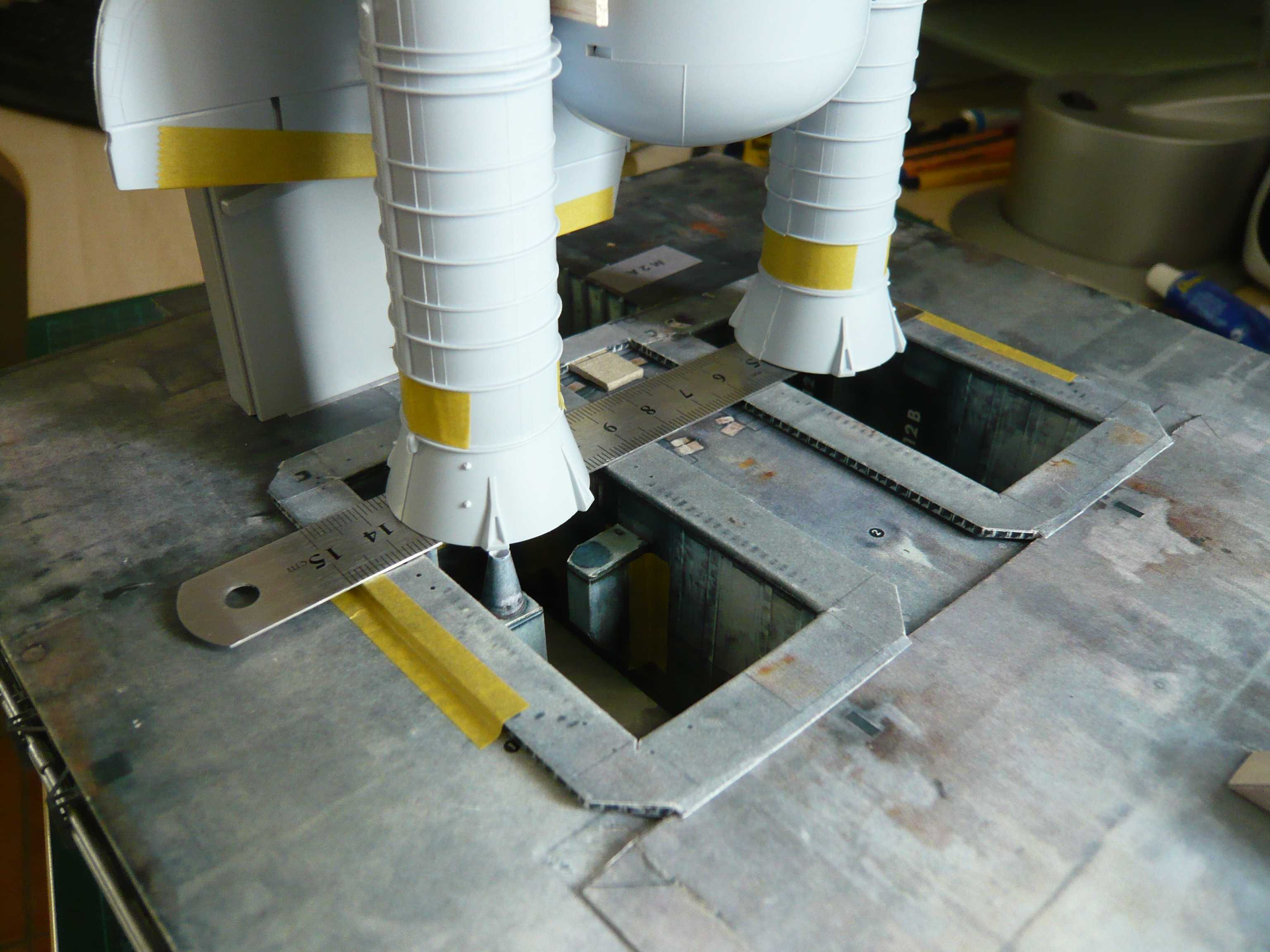
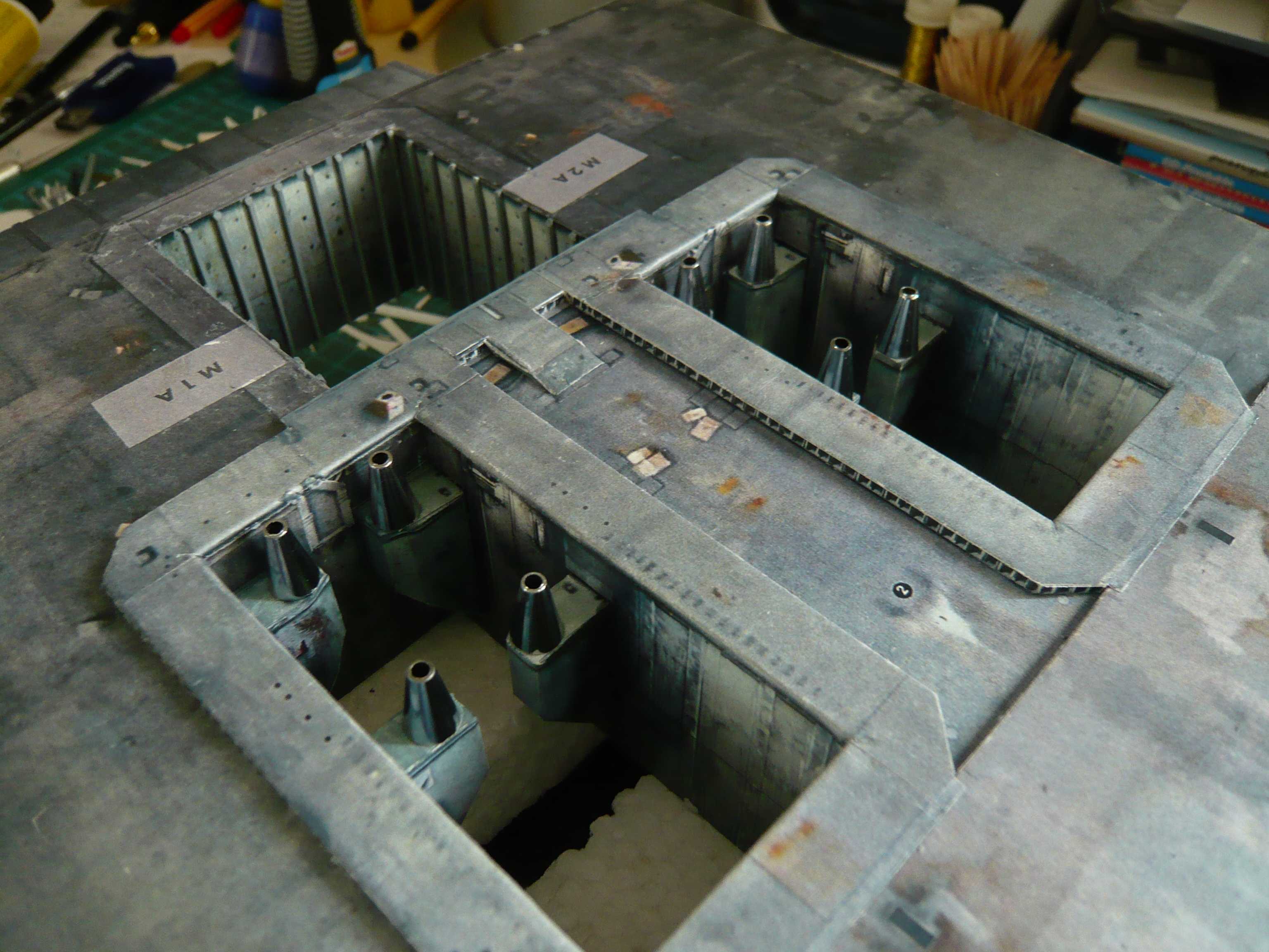
before gluing the SRB Blast shields I want to paste this time the SRB Supports, in order to have a solid reference plane for their fixation on the same height level. And to make exactly the glue, I have made a template for this.
As a result, all supports should have the same height.
On the support then the Hold down posts sit, that I’ll make from the ballpoint pen tips.
And this time the base plates on the SRB aft skirts sit directly over the marks for the Hold down posts.
Thus the center positions for the rear supports could be drawn now in order to being able to paste this by using the template also.
And all eight supports are sitting here in place, and all at the same height. 
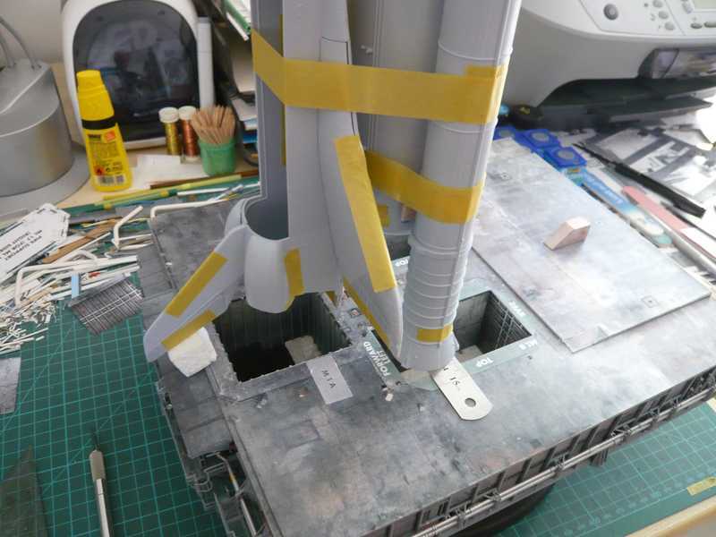
Thereon stands now the SRB-ET combination for fitting, that looks pretty neat. ![]()
Next time then continues with the Hold down post tips. ![]()
Hello everybody,
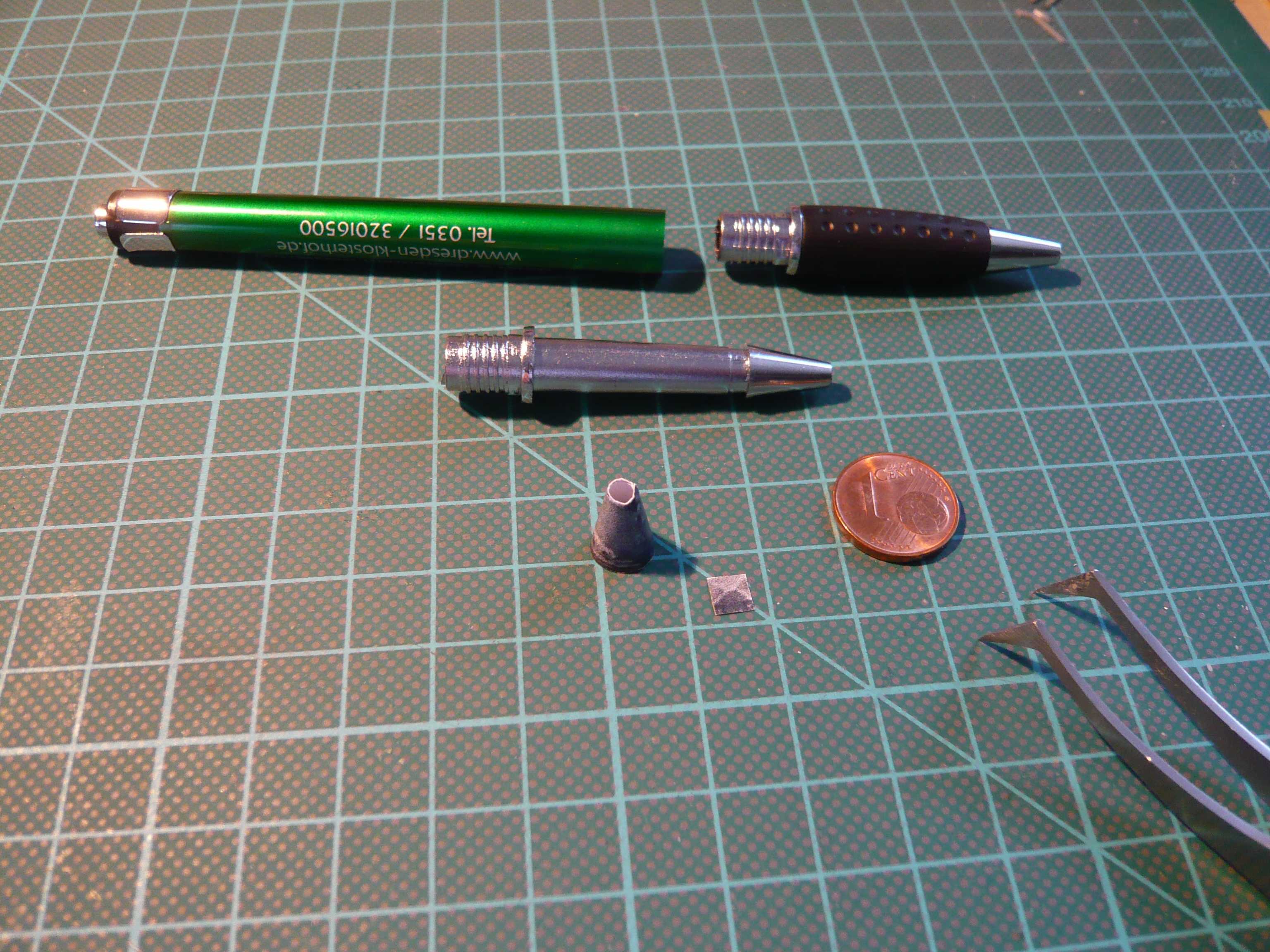
since today it is/was Sunday, a little bonus in memory of the poor ballpoint pens who had to bite the dust today. 
Shame about them, but their tips actually have the appropriate dimensions for the Hold down posts. The Dremel with the mini saw already stands by.
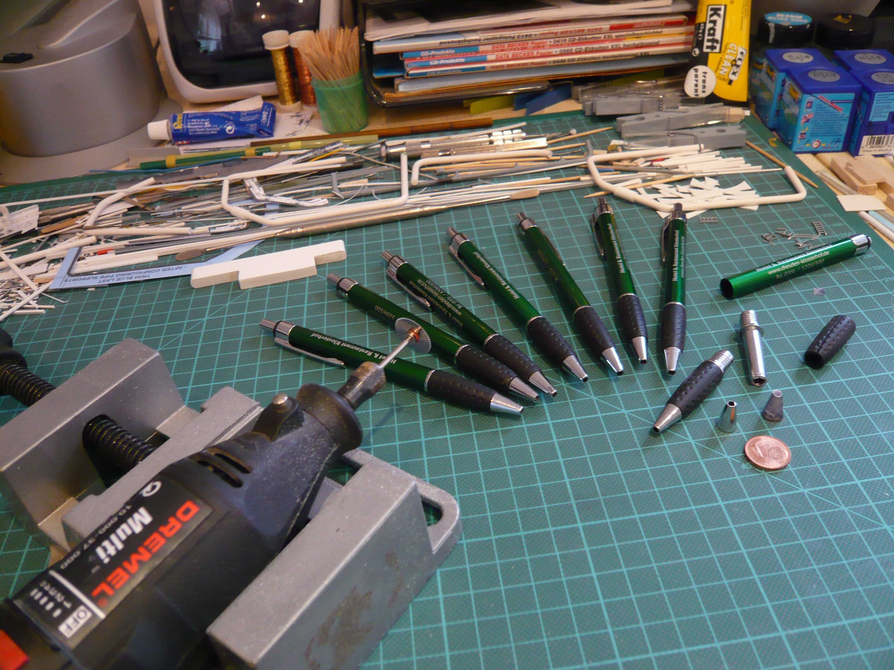
So let’s go, and away with the rubber handgrips, so that one can nicely cut behind the tip.
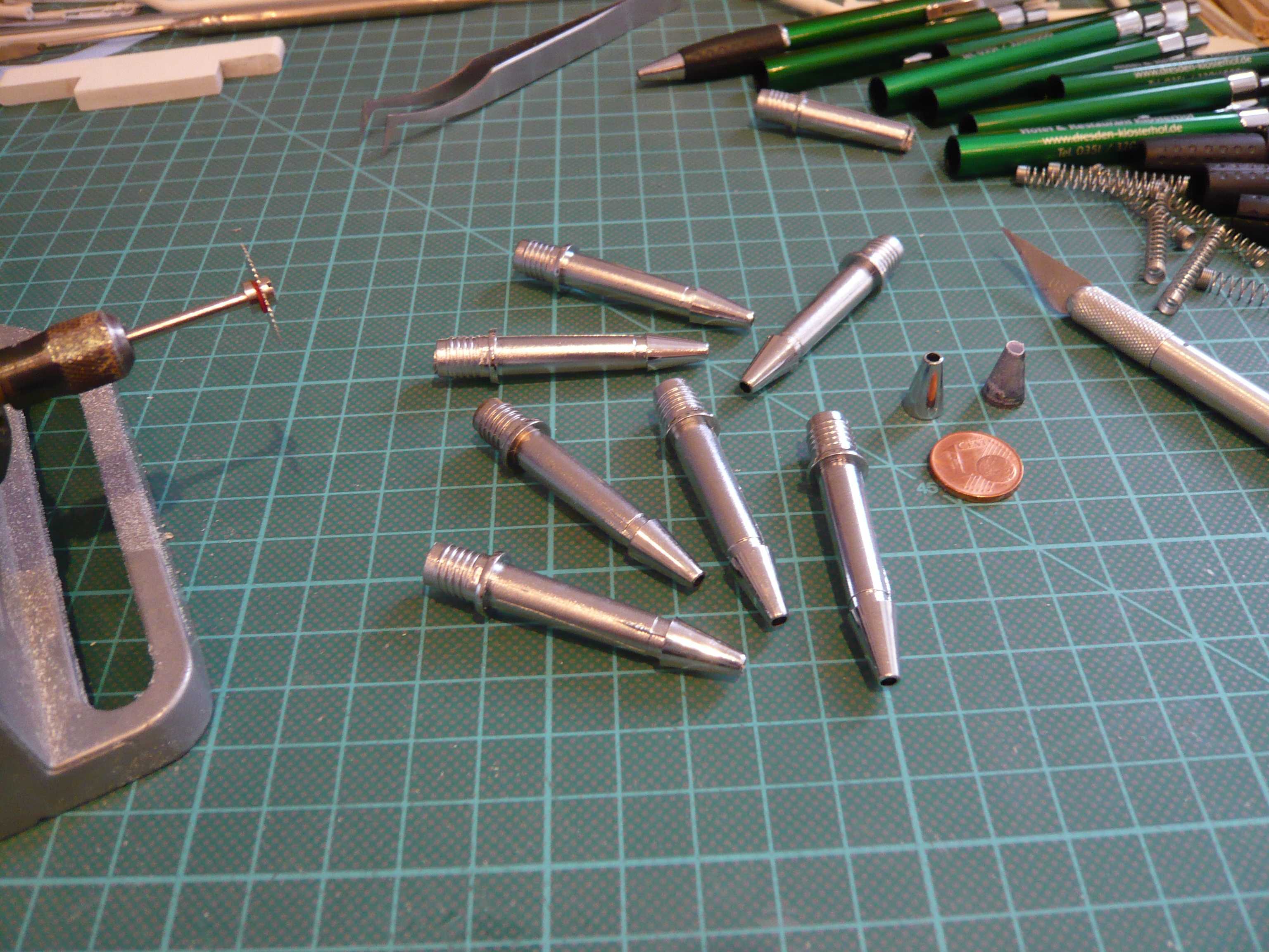
And as quick as a flash were already sawed off the tips, such a waste of material … ![]() but the end justifies the means for the loved hobby.
but the end justifies the means for the loved hobby. ![]()
And now sanding the ground a little smooth, and already is the raw form.
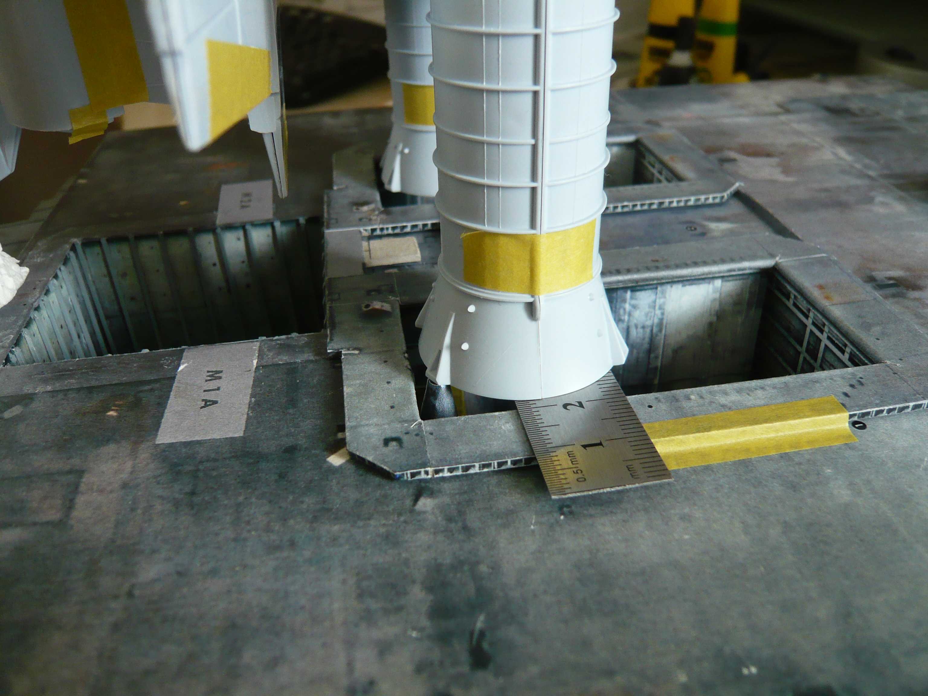
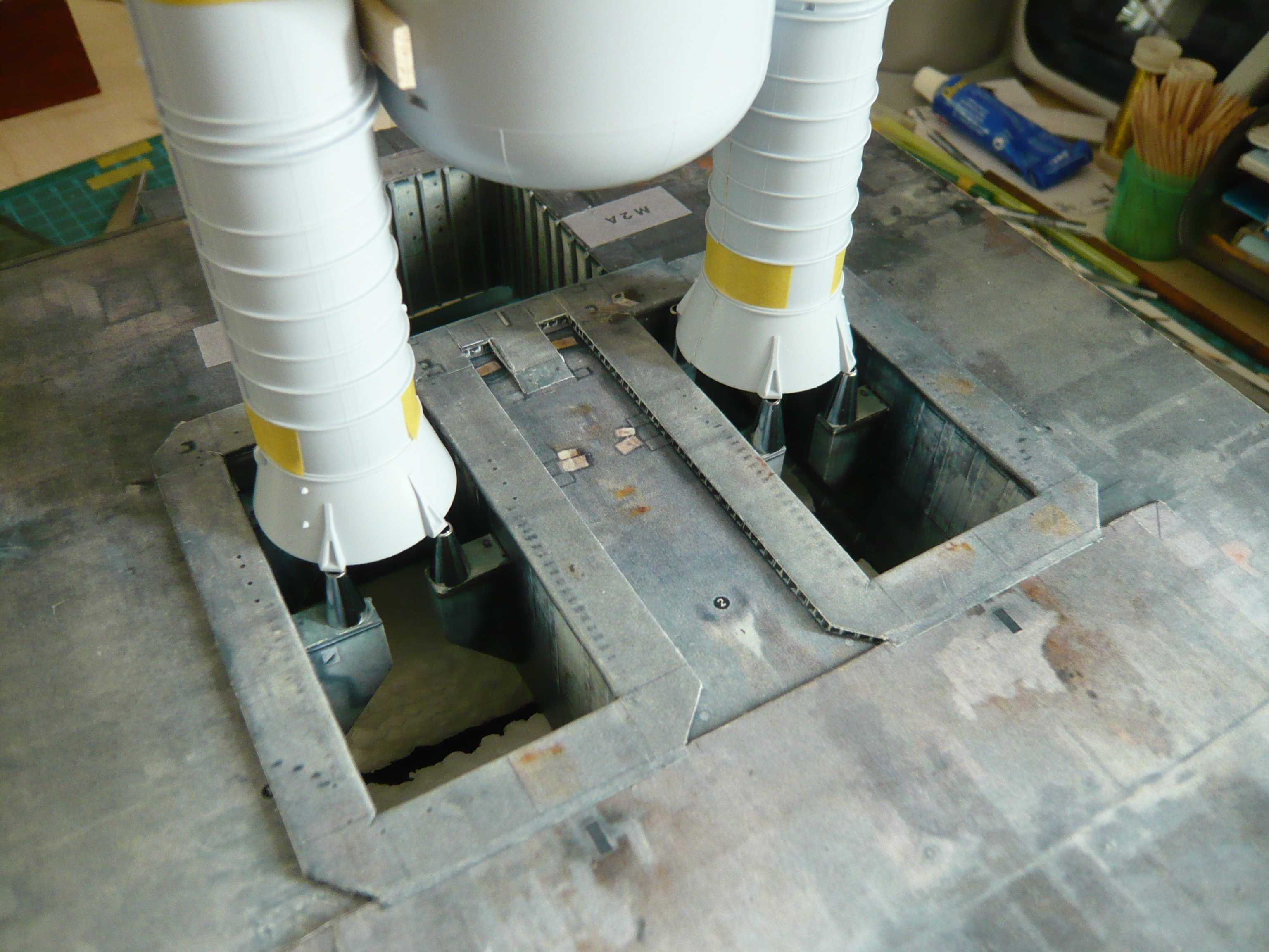
And here only a test fit on the support,
and the SRBs already provisionally put on it. And as one can see, this fits together quite well.
That’s why I was now able with a clear conscience the SRB Blast shields to glue up finally,
the image more and more completes, no comparison more with the demolition images.
And now everything looks again like before the surgery.
Next the tips must now be modified further, therefore plastic rods are pasted into with thin wire pins as “Bolts”. ![]()
3 Likes
Looks good ![]()