Hello everybody,
here we go, because after all I want to complete the seemingly endless chapter of analyzing the undersized Revell parts soon, which on the one hand is pretty stressful and for some guys this might be boring, but on the other hand this must also be done to know where the (Revell) rubber meets the road, to avoid being caught out at some point. 
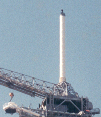
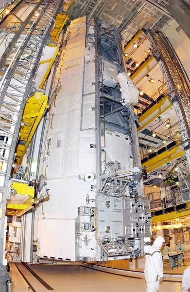
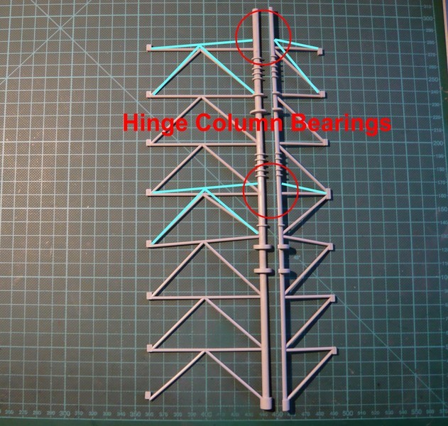
And so let’s have a look at the rotation axis of the RSS Hinge Column (Ø 42’'), around which this Monster construction must be pivoted for loading and unloading the orbiter up to the MLP for what these two huge Hinge Column Bearings are installed on the axis. 
The connecting structure has a triangular cross-section and a similar framework as the FSS, and is directly connected with its tier floors. 
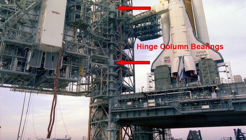
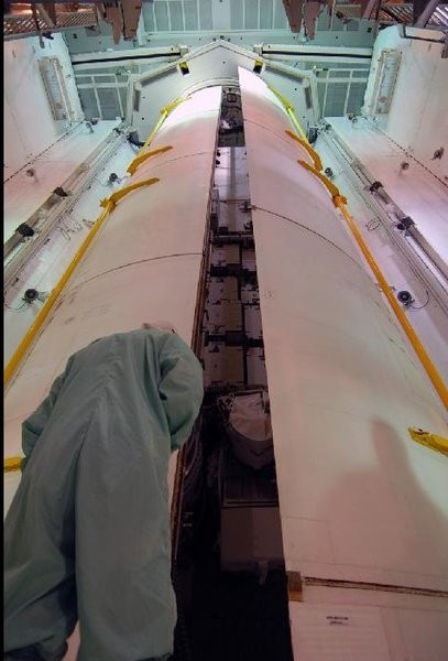
Source: retrospaceimages.com (STS-6)
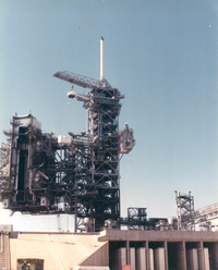
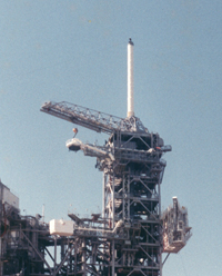
In these images, the two frame parts (11, 12) are fixed only provisionally at the tower.
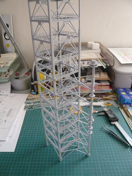
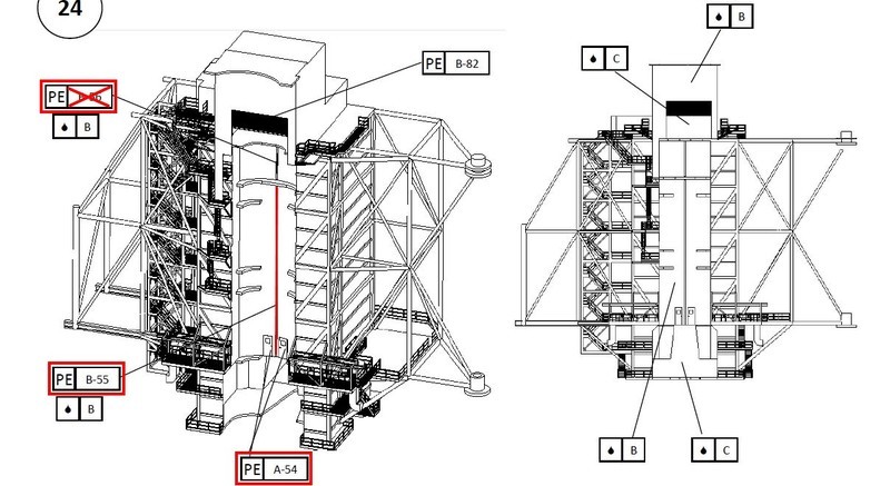
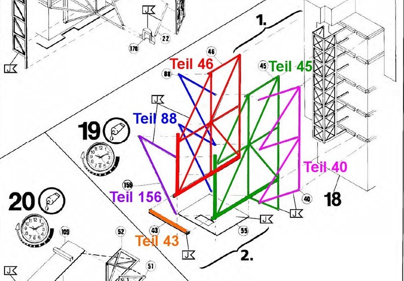
Comparing the structure of these frame parts with the NASA Demolition plan (Pad 39B), one notices that the arrangement of some struts don’t conform with the true run (light blue),  what can be seen from the following picture. This apparently has to do with these two bearings, which namely sit exactly at these points of the rotation axis and need an appropriate place, which is why this struts sit a little higher.
These facts must be considered in more detail in connection with the planned heightening of the FSS and the lateral RSS support frame anyway, as this will result in further shifts what will be explained still. 
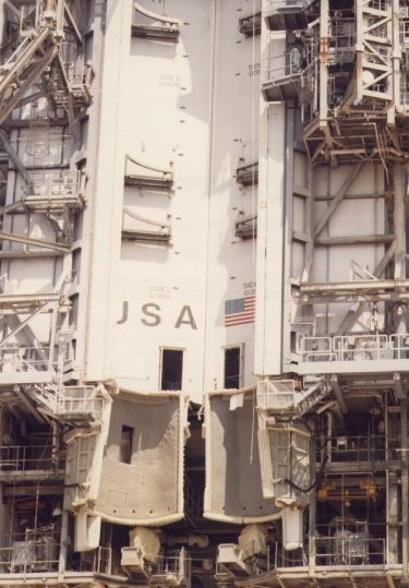
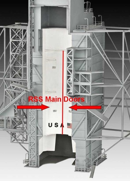
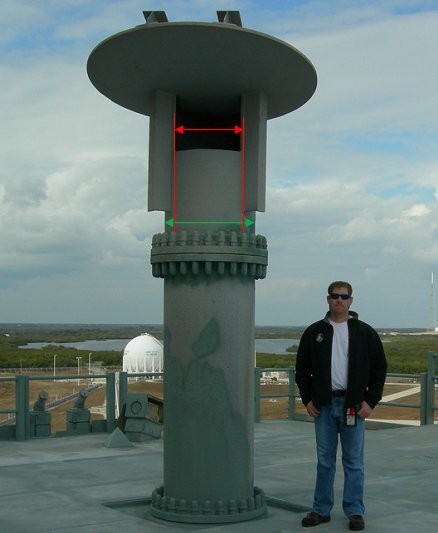
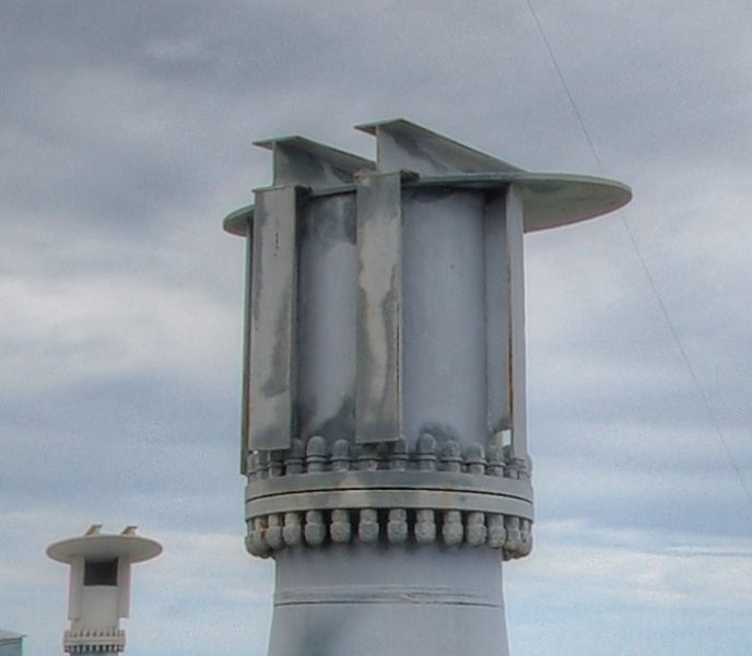
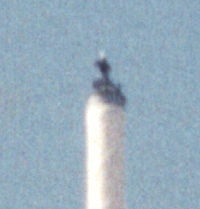
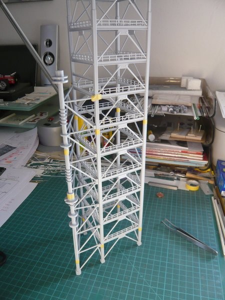
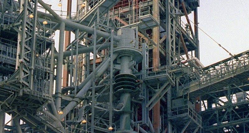
Here you can see the two bearings of the rotation axis again in detail, initially the upper bearing,
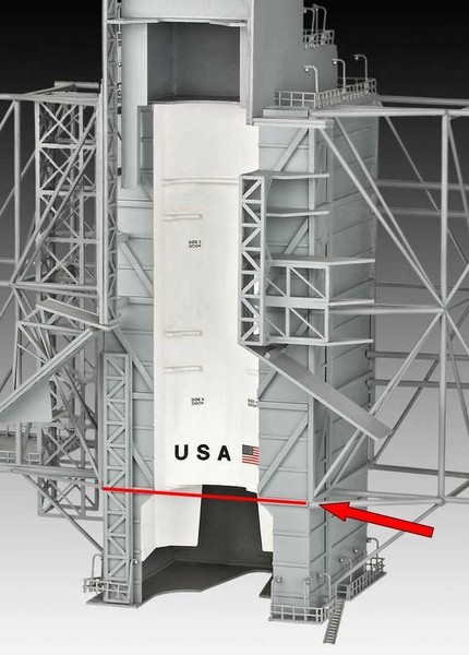
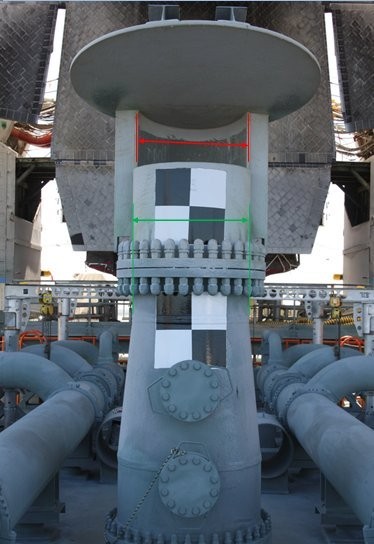
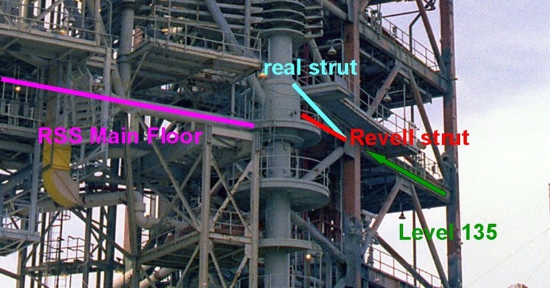
and here the lower bearing, which at Revell but unfortunately too deeply seated, and thus also the RSS, because their Main Floor is exactly at this level.
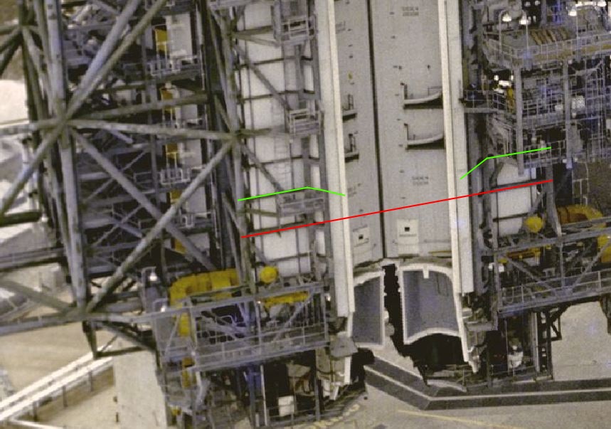
For orientation here the Level 135 is marked, and how one can easily see, this bearing is thus approximately at a height level with the lower edge of ceiling. If one extends the fleeing, one sees that the middle horizontal struts of both Revell frame parts (in the previous image) meet directly to this bearing and would block it, but this would be nonsense.  And that’s why these struts can only run to the rotation axis above the bearing, namely as shown (light blue).
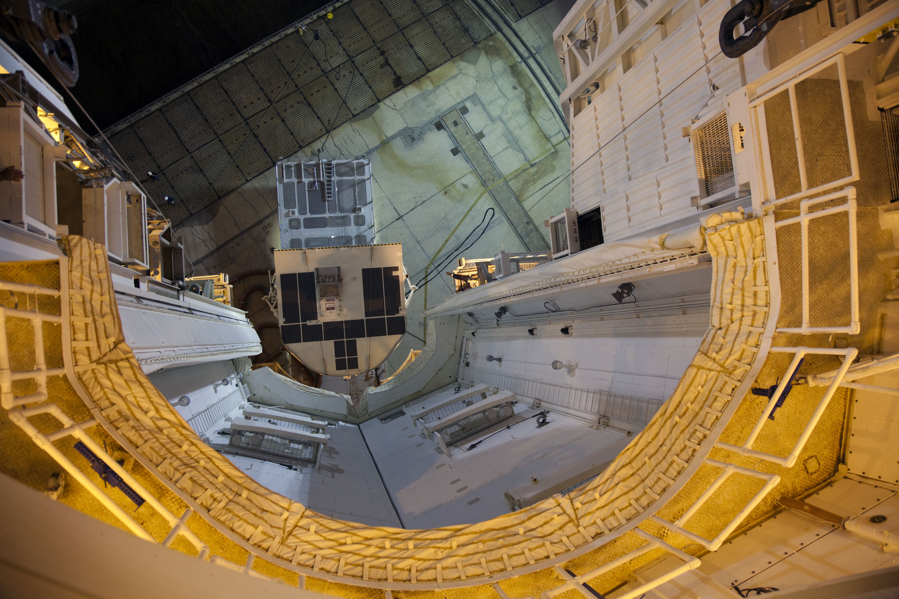
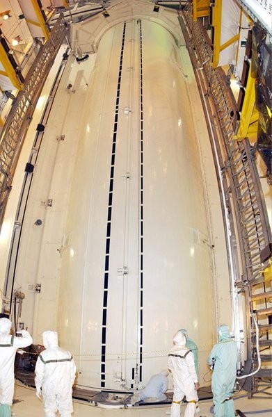
In the following panorama image you can see this a little bit clearer, although the Centaur platform and the walls of the Weather Protection System conceal some things, but both systems at the STS-6 were not existing.
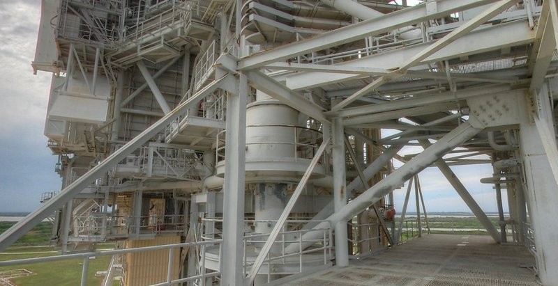
Source: nasatech.net
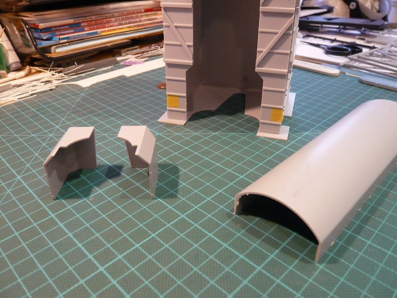
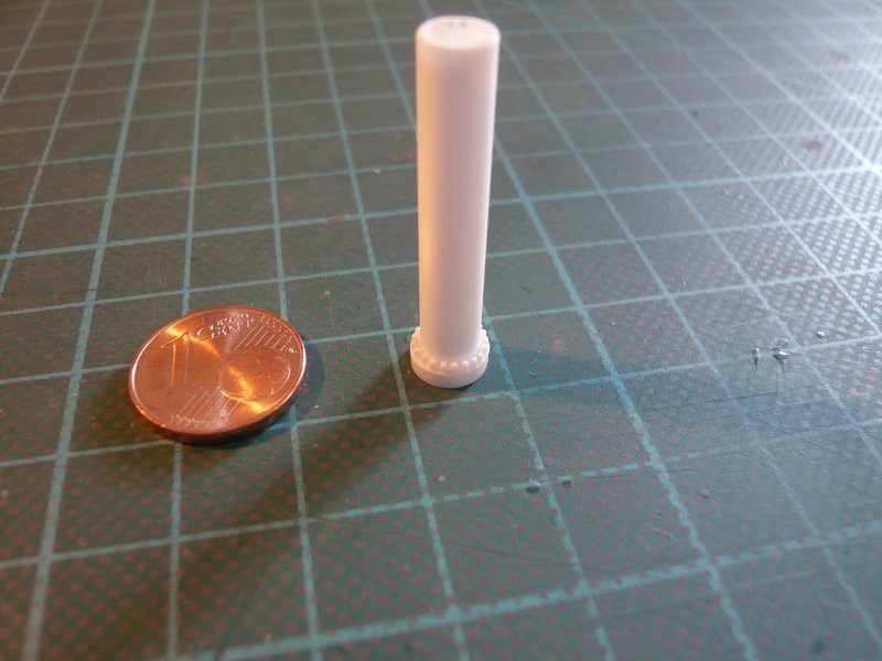
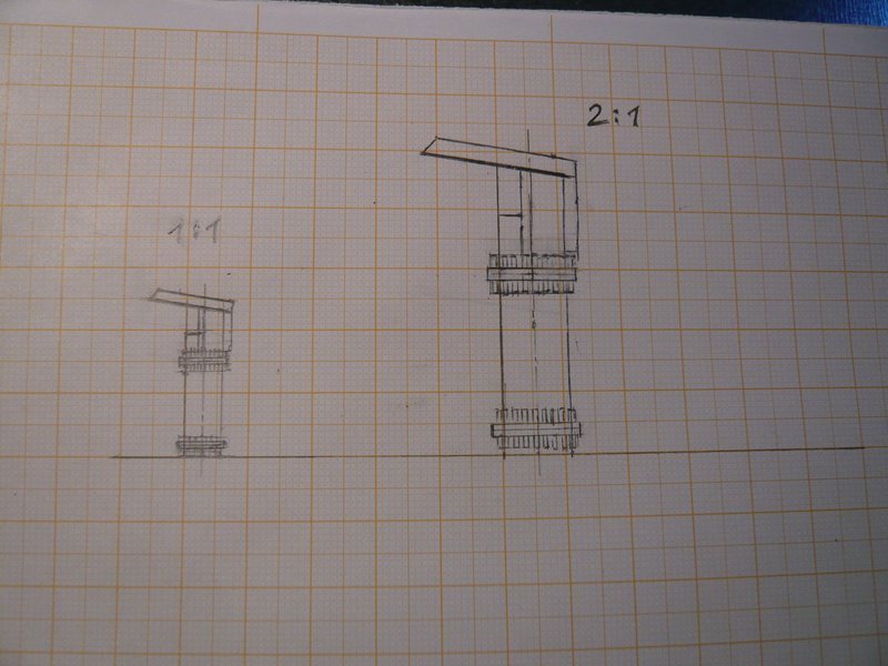
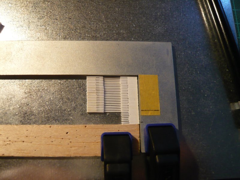
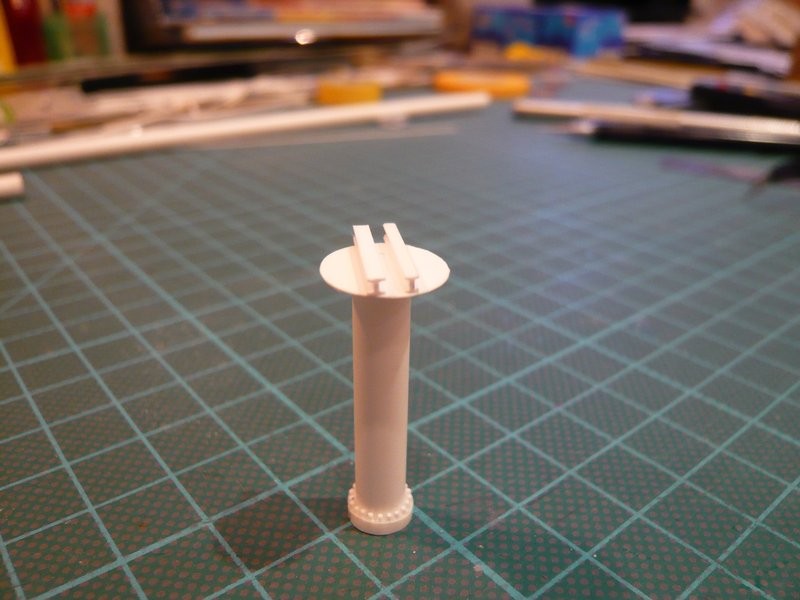
And these are the corresponding Revell parts of the bearings (169-171 and 173), but both the diameter and the height are too small. In addition, the upper bearing has no cover plate (173) like the Revell bearing. 
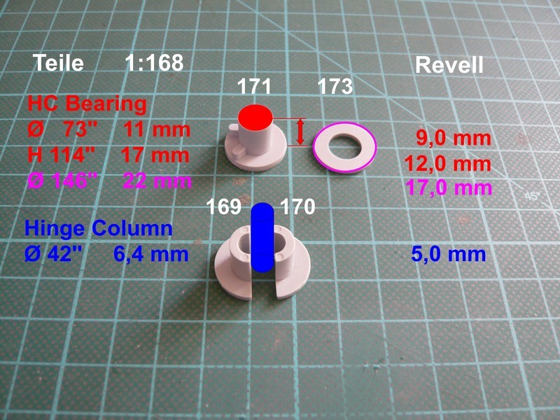
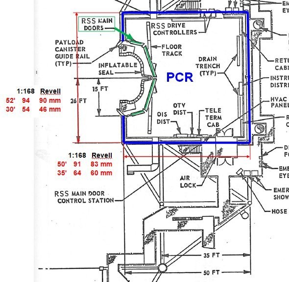
For these dimensions it should be noted that I could find only the diameter of the Hinge Column (42’') in the NASA plans which I have used as a reference value for the scaling of the bearing dimensions on the basis of detailed photos.
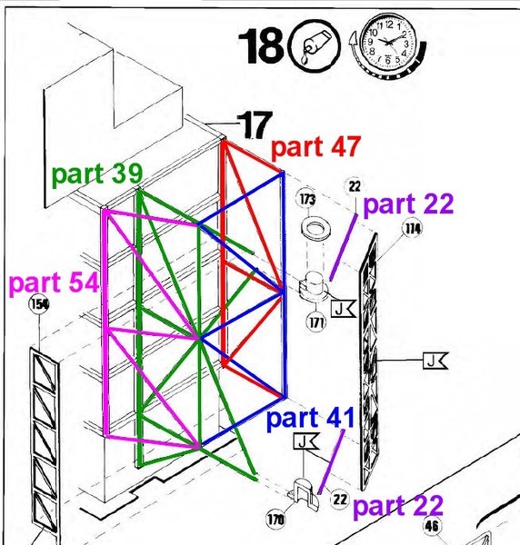
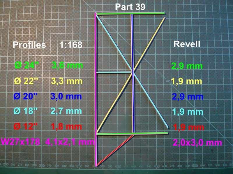
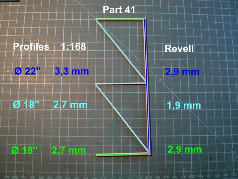
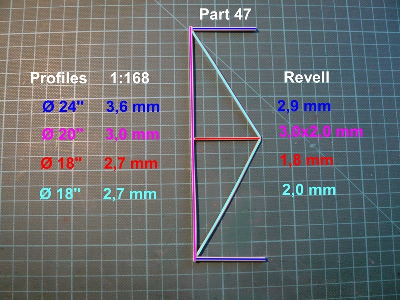
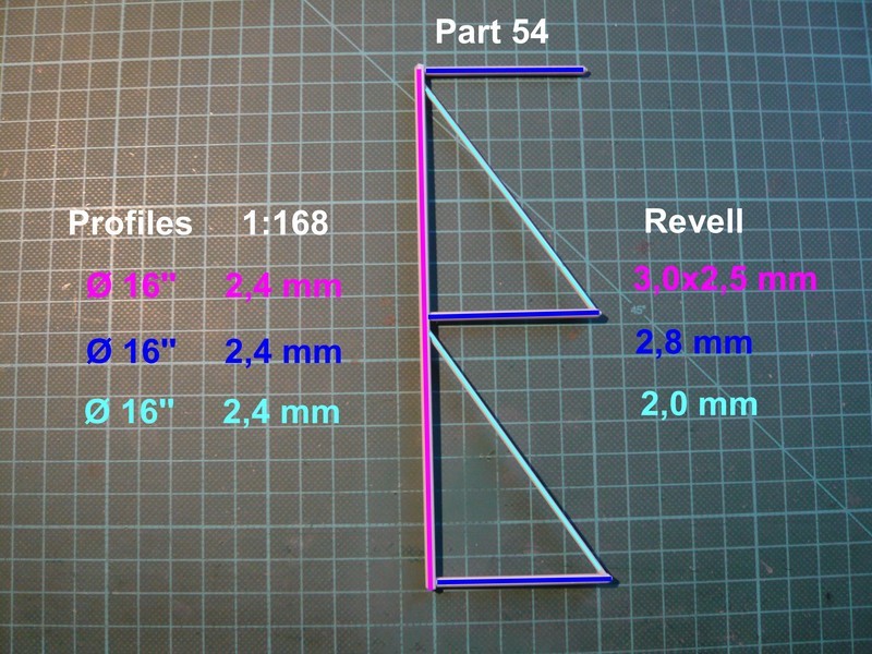
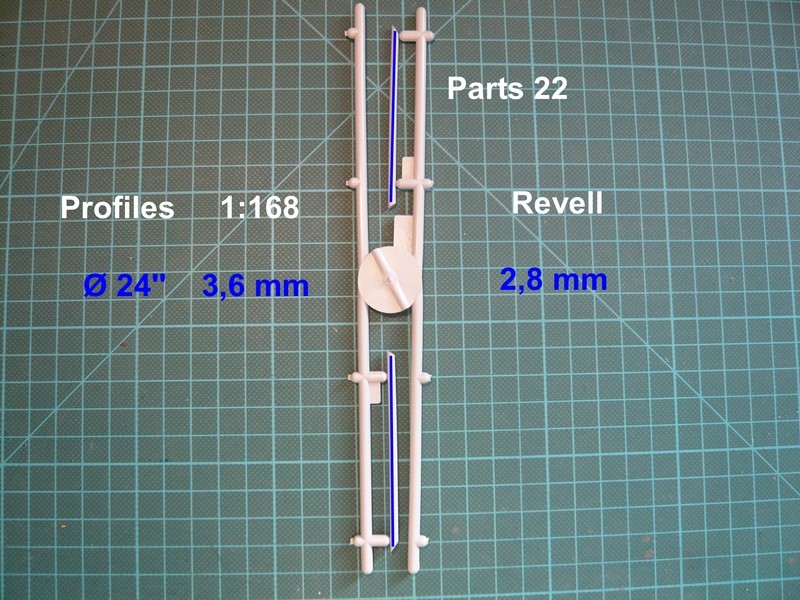
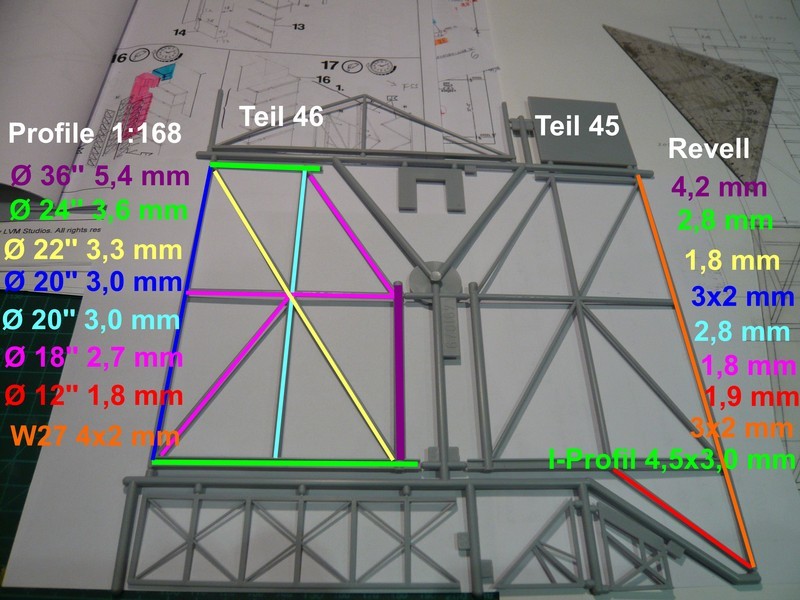
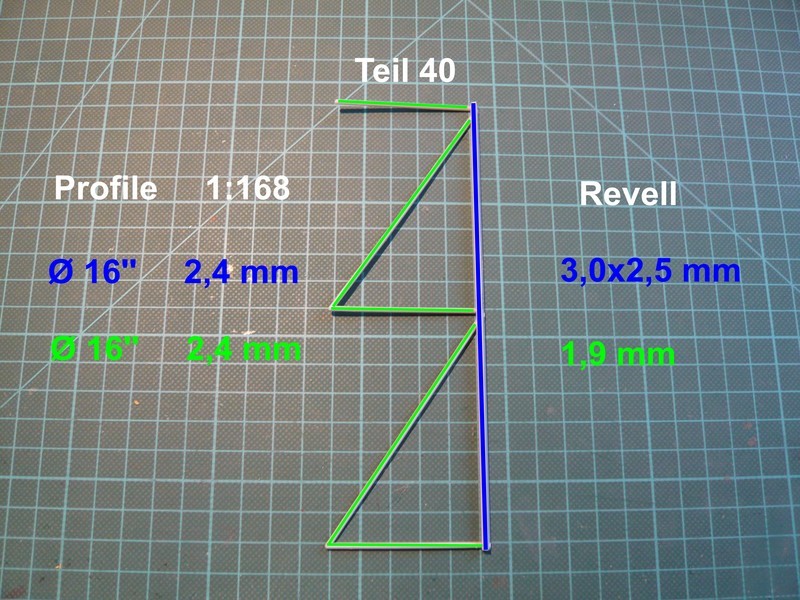
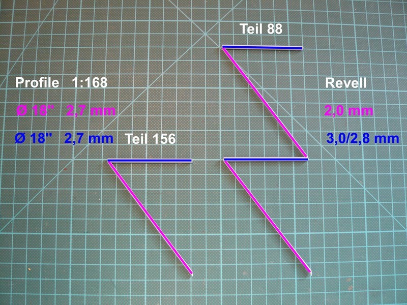
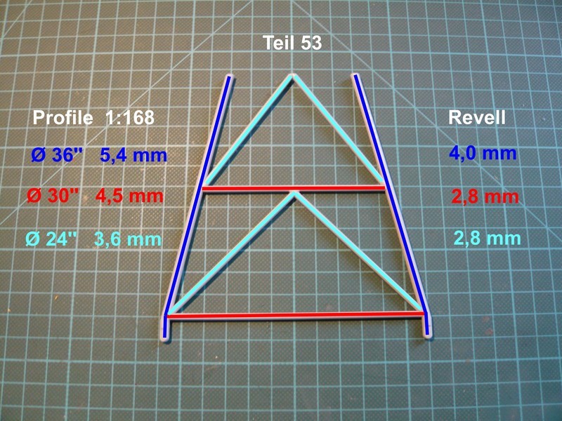
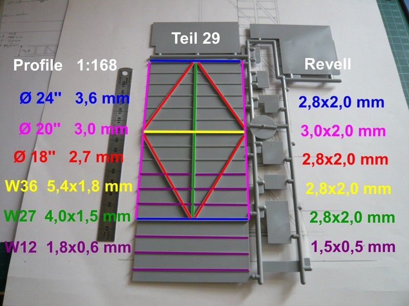
And this is the comparison of the profile dimensions of the two frame parts 11 and 12 with the scaled values (1:168).
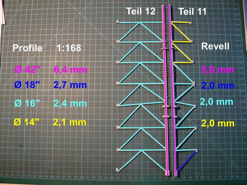
As you can see, all other profiles except for the 14’’ tubes are partially undersized clear, whereupon the diameter of the rotation axis (42’') with Ø 5 mm lies clear below the nominal value of Ø 6,4 mm (1:168).
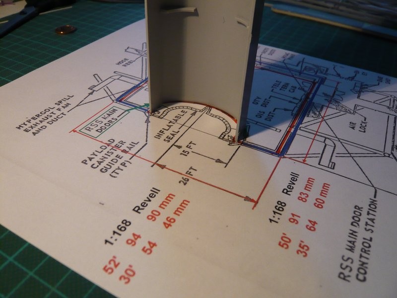
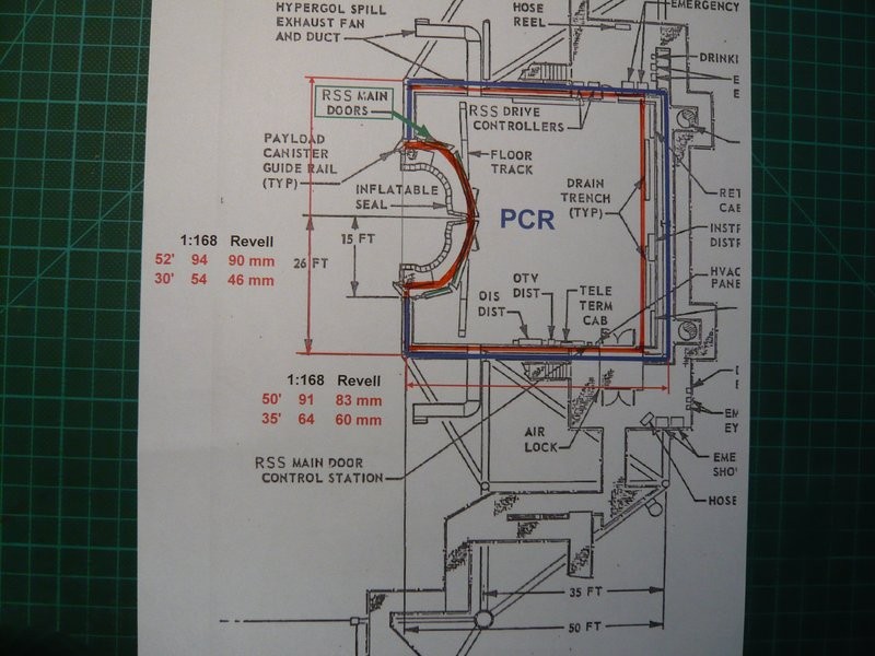
That was it but now for today. Next time I have to return once more to the outer RSS support structure, because some parts are still missing. And as I have found, the analysis of the backside of the PCR is missing so far, what remains to be done.
But soon this crazy Sisyphean task is done, and then I know what is to change, or not …