Thanks John! ![]()
Regarding my attention to detail, I often ask me, if that is more curse or a blessing? ![]()
![]()
Thanks John! ![]()
Regarding my attention to detail, I often ask me, if that is more curse or a blessing? ![]()
![]()
lol … its a 2 edged sword !!
Definitely! ![]()
But even though I sometimes have to swear and could throw everything into the corner, ![]() in the end the joy of the successful solution outweighs it and shows me that it’s worth not giving up.
in the end the joy of the successful solution outweighs it and shows me that it’s worth not giving up. ![]()
![]()
Hello everybody,
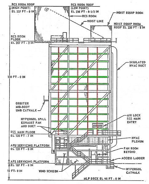
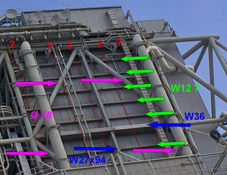
thanks to my friend James MacLaren (39B) who was working during the construction on Pad 39B and knows both pads very well, I have now a little more clarity on know what profiles were used for the already discussed horizontal and vertical lattice structures on the PCR walls, which I have highlighted in this drawing. ![]()
These girts (green) in the horizontal lattice structure directly on the walls are apparently W12 Beams (Wide Flange Beams), and the vertical lattice structure between them consists of W6 Beams (red). ![]()
And on this lattice structures is located the RSS frame structure that envelops all, as well as this rhomb from Ø 18’’ tubes.
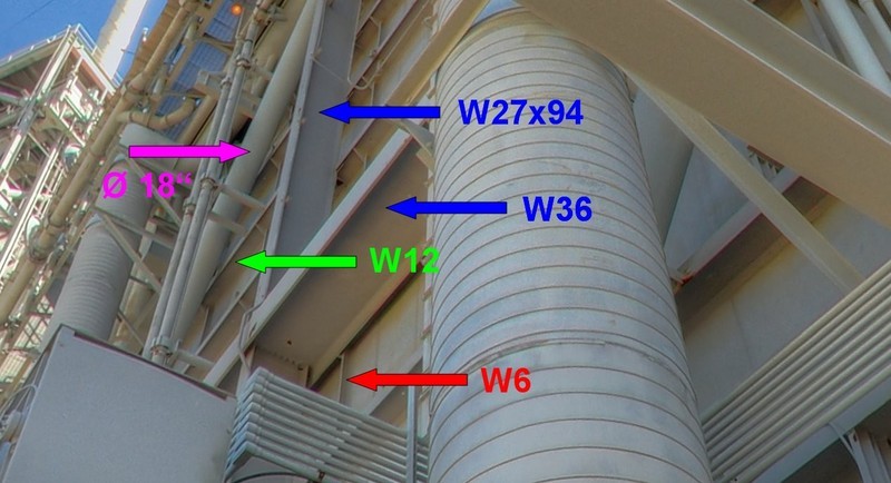
In this view, the arrangement of the profiles is even clearer to see. ![]()
Next, I will deal again closer with the Elevator shaft and the HER. 
![]()
Hi guys,
as you can see in the photos of of the dismantled RSS on Pad 39B everything much clearer, here is a last clarification to the stairwell next to the elevator shaft. ![]()
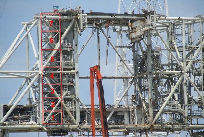
Source: flickr.com (Andrew Scheer)
As you can quite clearly see here, the stairwell above the RSS Main Floor, actually has seven floors, and not six as in the LVM Detail kit. ![]() But they are not arranged uniformly distributed over the total height of the frame structure.
But they are not arranged uniformly distributed over the total height of the frame structure.
Rather, the bottom three floors have approximately the same height, and also the top three, whereupon whose height is slightly larger. The 4th floor is slightly lower than the upper three and goes out about the central transverse brace of the frame structure, like the 7th floor something goes over the upper transverse brace addition.
Whether this finding, however, would now convince LVM thereof, to modify their stairwell accordingly, remains pure speculation, it would be welcomed in any case. ![]()
![]()
Hello everybody,
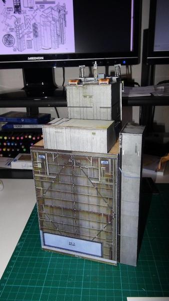
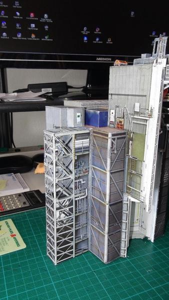
before we speculate here any longer, I have very interesting images of my friend Michael (mk310149), who has built David Maier’s Launch Pad (1:144) from paper. And so you can a lot more recognize than on the previous light and shadow pictures, even though some details are indicated in a conventional manner only by clever textures. 
And as you can see easily, the elevator shaft has actually this inclined wall running up to the PCR. 
Source: papermodelers.com (mk310149)
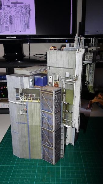
However, this wall is no more detailed behind the stairwell, which is why the doors are missing, ![]()
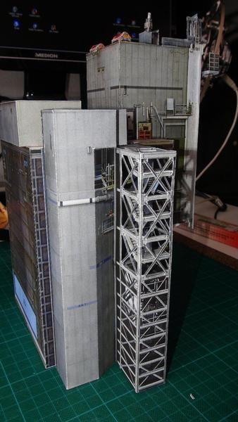
Source: papermodelers.com (mk310149)
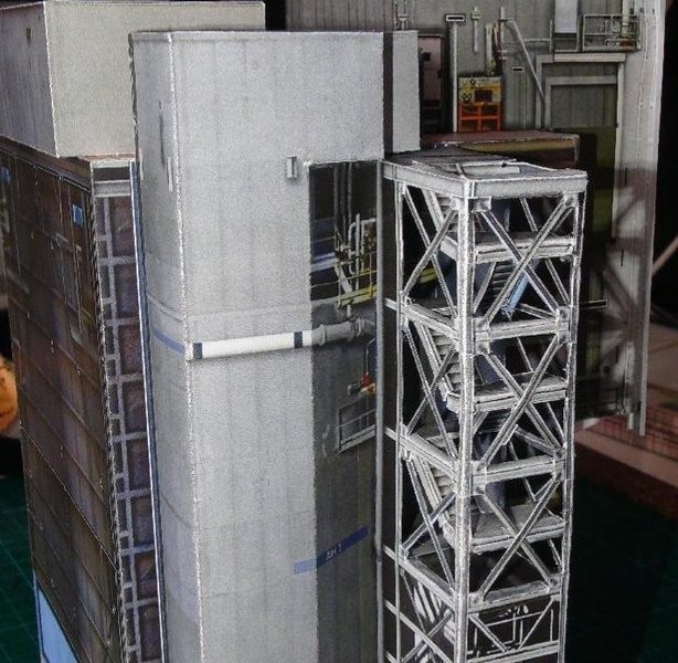
or one has to imagine it behind the pipes. 
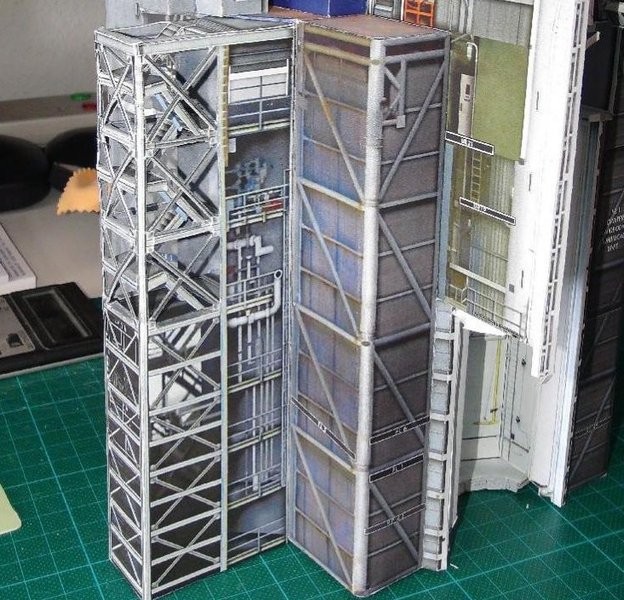
Source: papermodelers.com (mk310149)
As you can also see, the stairwell is interrupted only in the top three floors and has stairs, the lower four floors do not, but are only hinted at. ![]()
But the stairwell has seven floors, and the different frame-division also corresponds to the original, so at least the elevator shaft problem is likely to be clarified.
And now I also have got the confirming by my friend James MacLaren (NSF-Forum) that the elevator shaft “lobby” was triangular and the Revell model is totally wrong in this regard, which was to be expected.
![]()
Wow Manfread, this is the part I was waiting for. I will like to see how you fix the tower structure issue. It looks like you also have the Photo-etch set I have and looks like you are going with David’s paper structure, Revell plastic, and PE combo to achieve the best results. Best of all worlds!
Sorry for going quite on you but I’ll reply to your message soon. Keep it coming here as I am saving everything. It’s a full blown buffet for space shuttle lovers ![]()
Thanks Mike for your comeback and your nice compliments. ![]()
All well and good if it weren’t for those annoying scale problems of the kits. ![]()
![]()
Hi all together,
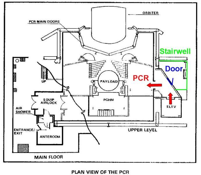
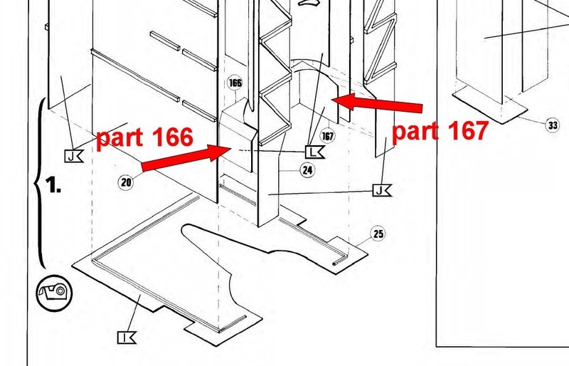
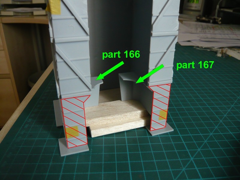
now I have actually found a few great drawings in Capcomespace, finally to obtain a clear overview of the PCR and the Elvator shaft with the inclined wall, which provide the final proof. ![]()
As you can see it, one comes out of the elevator shaft into this triangular “lobby” and then passes through a doorway, which is not a door but an open entrance, directly into the PCR, which is a Clean Room. And in this wall I have indicated one of the doors, which should give it there.
I think that these are emergency exit doors, which are closed normally, but through which one can reach via the stairwell down when the lift should have a disaster.  For what should the staircase otherwise be good?
 ![]()
And in this drawing can be clearly seen also the platforms in front of the elevator shaft with the doors, where upon the platforms seem to be a bit too large, possibly from an early concept phase of the Pad history. 
I hope that’s about it on the subject elevator shaft.
![]()
The technical aspect of this build is impressive, not to mention the incredible scratch work. This is MUSEUM quality, and a hoot to watch come together, just sayin!
Ruck On, Bby!
Welcome Steve and thanks for your enthusiasm, 
stay tuned and keep up having fun.
![]()
Hi everybody,
and therefore the modified lift shaft should later once look something like this, of course, with six doors in the inclined wall.
And on top of the RCS Room Floor there must then be also a cut between the Elevator shaft, the RCS Room and HER, what I’m going to sketch sometime soon.
![]()
Hello friends,
today I will continue with my FSS analysis of the Revell Kit.
This has therefore lasted a little bit longer, because for the necessary dimensions of the Tower structural elements in addition to the Pad 39B Dismantling plans I had also to rummage in the old LUT plans. 
But for that I now have a good overview, I want to present now. ![]()
For the FSS frame construction Standard Steel beams were used, their configuration can be found in the AISC Standards (American Institute of Steel Construction). These include among others a wide range of H-, I- and T-beams, etc., whose designations first getting used to, especially since in the US there is no metric system, but all dimensions are in feet and inches, and so I had to convert everything. But to this later more with concrete examples.
First, again looking back on some already discussed scale facts.
The lateral parts of the Revell Tower are 447 mm long, which corresponds with a tower height at Level 295 of 75,3 m and a scale of 1:168, what is the reference standard for my launch pad.
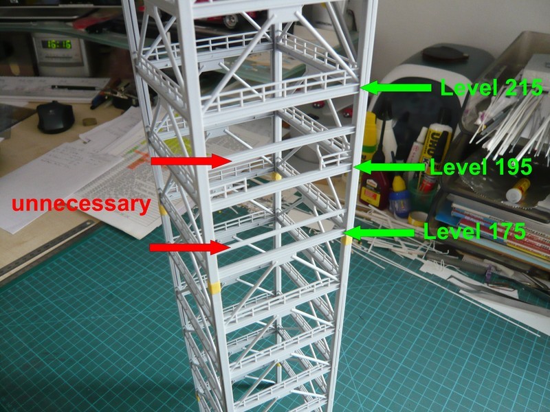
While the lateral parts in Revell’s kit new edition now all have the same structure construction, in the old kits there were on the west side between Level 175 and Level 215 these two cross beams (red), apparently to install the Emergency Egress Sytems (EES), but which does not exist and, consequently, so are not required.
And so now to some details of the FSS-frame structure, whose construction over the entire height from Level 75 to Level 295 is almost identical in the Revell kit, which unfortunately is not true. 
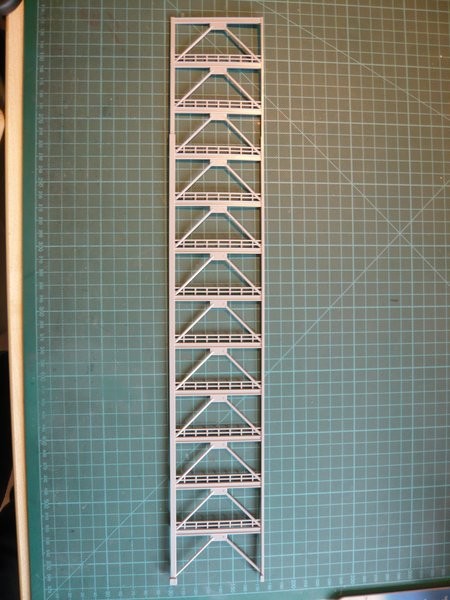
The changes from floor to floor are indeed barely noticeable, but still present.
Both the lateral spars (welded square tubes) as well as the outer frame supports decrease upwardly both in cross section as well as in wall thickness.
The lateral spars have shortly above Level 240 a transition from Square tubes (Box Columns) to H-beams (Wide Flange), and are changing from H-beams (W14x193) to I-beams (W14x61).
So much for today, next time I’ll show then the deviations of the Revell’s profiles of the frame structure in detail, what is something special then.
![]()
Hello everybody,
and thus now in detail to the FSS frame construction, which is undersized by Revell and quite simplified. And as we have already noted, all FSS levels are too low, due to the 7,5 cm too low height of the tower (1:168). ![]()
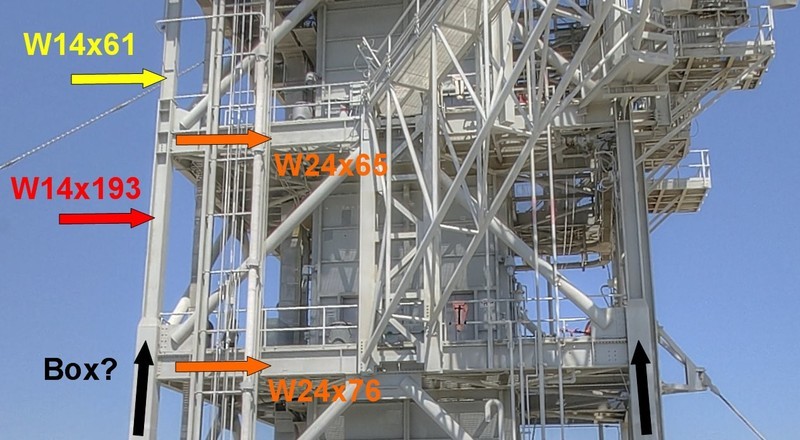
And now to the individual structural elements of the frame structure, the dimensions of which I found with two exceptions in the Pad 39B Dismantling plans after a long search. And this concerns specifically the edge lengths of the upwardly tapering square tubes (Box Columns) at the foot of the tower and at the transition to the W-beams above Level 235. But I was quite glad to have found at least two box dimensions in the central region. ![]()
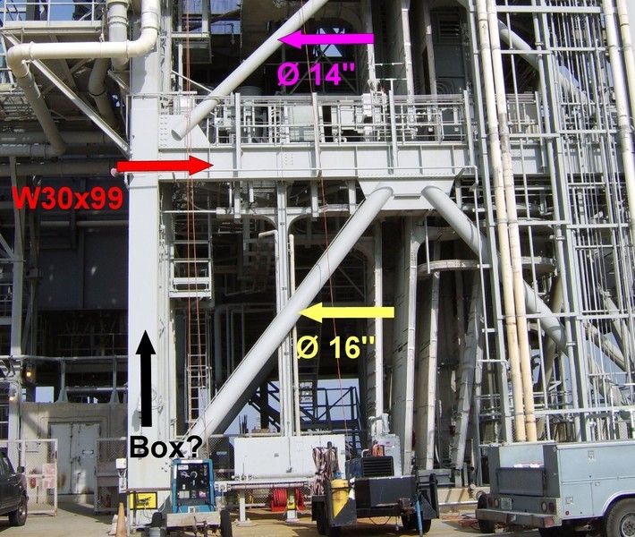
So I calculated the edge length of the box-spars at the bottom of the tower from this picture based on the height (30’') of the first frame support W30x99,
and the corresponding edge length of the spar at the transition from this picture based on the local frame support W24x76.
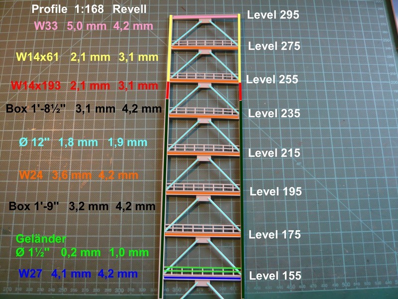
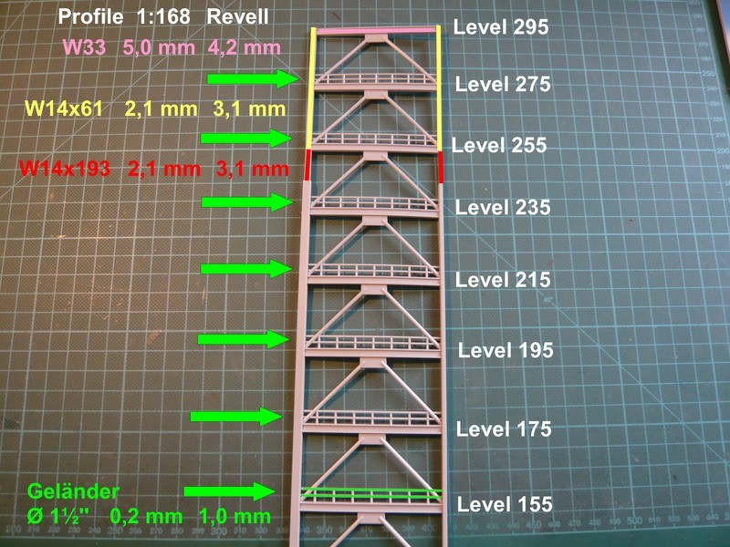
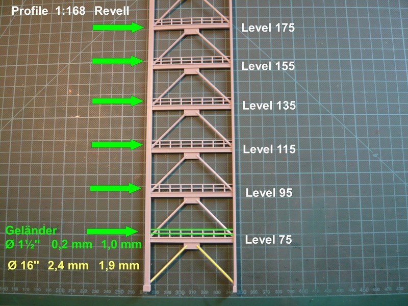
And therefore still to these two profiles after the transition, which however, are not gradated in the Revell kit. ![]()
While the W14x193 is a typical H-beam with a square cross section of 15,5’‘x15,7’', the following part W14x61 (13,9’‘x10,0’') corresponds more likely to an I-beam.
And so this looks in detail, whereupon I again have indicated the scaled 1:168 values next to the relevant profiles, and to the right the dimensions of the Revell parts. I hope that the details are still to read and the colors are not be too confusing. ![]()
What should one immediately notice is the fact that all Revell frame supports from top to bottom have the same height of 4,2 mm, and all diagonal struts the same diameter Ø 1,9 mm. During the struts in the lower part to Level 135 are slightly undersized, in the upper part they nearly correspond with the actual conditions.
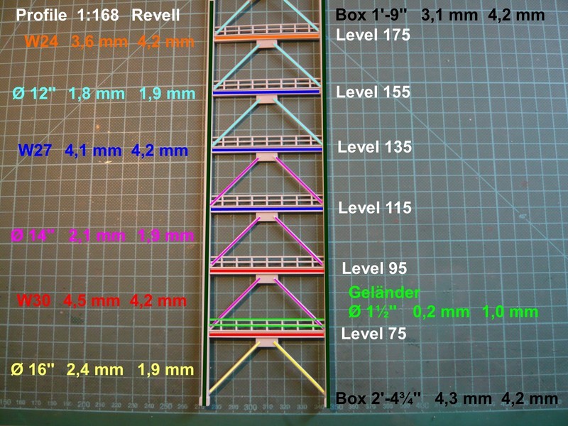
The deliberate cross section reduction of the frame supports however Revell has less well implemented upwards.![]()
It is similar with the side beams, which have the same cross-section from the bottom up to the transition and do not taper towards the top. ![]() And that is in fact already a clear difference, because these huge square tubes taper from approx. 760 mm, edge length (2’4¾’') at the bottom (wall thickness 90 mm), after all, just over half to approx. 356 mm (1’8½’') at Level 235.
And that is in fact already a clear difference, because these huge square tubes taper from approx. 760 mm, edge length (2’4¾’') at the bottom (wall thickness 90 mm), after all, just over half to approx. 356 mm (1’8½’') at Level 235.
But the really most serious deviation from reality represent the railings, because they are lot too strong with Ø 1 mm, what might find less attention. However, one must say that these diameters can not be realized by means of injection molding, but rather probably only with PE parts. ![]()
So my mission of inventory making of the greatest deviations of the Revell kit in my view would now almost complete with mainly. ![]()
How one should deal with it, will have to be shown therefore, ![]() and everybody has to decide for itself.
and everybody has to decide for itself.
Therefore next time another approach to the diagonal struts in the lower section to Level 135 that I’ll probably replace entirely. ![]()
![]()
Hello guys,
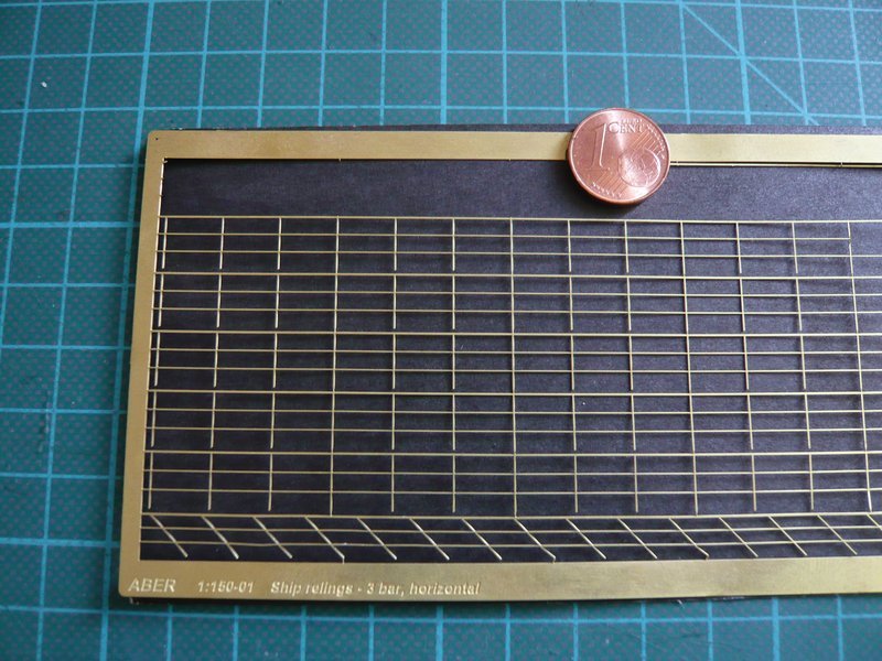
because the chunky railings has left me no rest, I have tested my PE railings of ABER in order to have a comparison with a true to scale part.
This railing can be found at ABER under Ship relings (1:150) and the dimensions of which should fit almost perfectly, especially as they are only 0,2 mm “thin”. ![]()
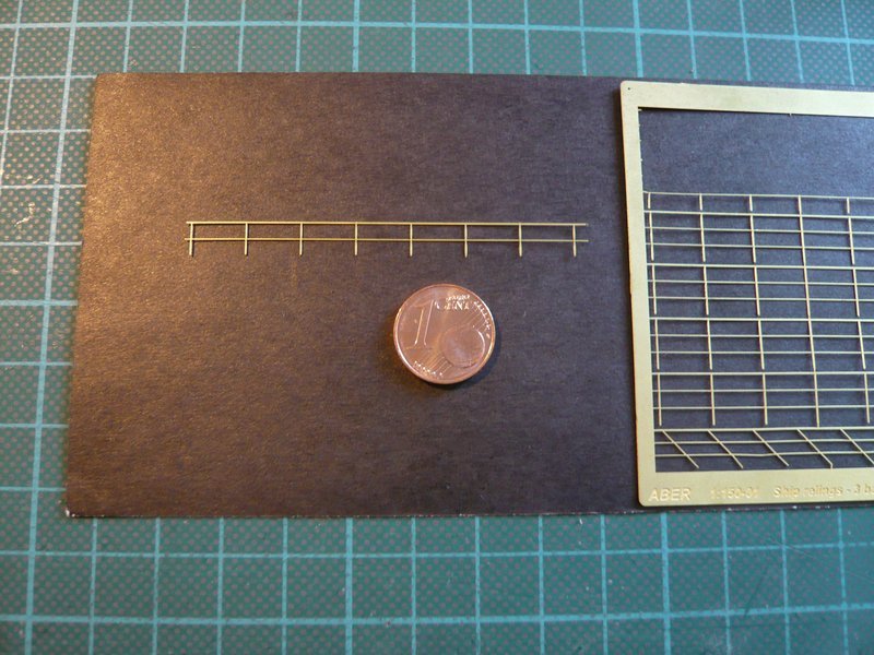
So I’ve even cut out an usable strip,
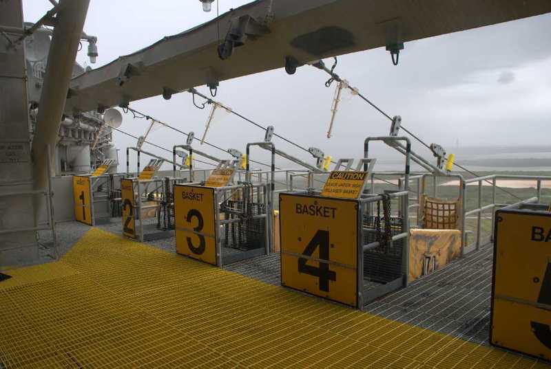
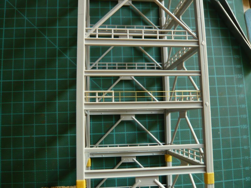
and have mounted provisionally on the west side of Level 195 at the local gap in the railing, which there is actually not existing because of the freedom of access to the rescue baskets of the Emergency Egress System (EES), even not these outer short pieces, what I had already mentioned.
But through this gap one can see the difference from the 1 mm “thick” railings of the Revell Tower very well what has impressed me. ![]()
And since we are talking just about, the overlying cross beam (in old Revell kits) does not exists at this place. It could be that Revell had tried to indicate the cross beam on which the ropes (Slide Wire) are attached, via which in the case of an accident the emergency baskets slide down, who knows?
But this cross beam is sitting a bit in front of the FSS framework, as you can see here.
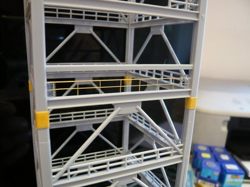
And here once more a taste one floor deeper on Level 175, where in the old kits both the railing and the diagonal braces completely lacking, and the cross beam is not true. Therefore the comparison with the chunky railing of the level below here is even better to see, I think. ![]()
And the longer I look so, the more I reach the view that it would be worthwhile, perhaps completely replace the Revell railings, what do you think? ![]()
Because later still the filigree grid floors will come, as well as the stairways and the elevator shaft of the LVM Detail Kits, which would then naturally harmonize well.
![]()
The work is still phenomenal… no let up in the detailing or the effort to make sure it all looks perfect …
The PE railings are a game changer… they look so much better than those chunky kit ones ![]()
Thanks John for your kind words, these endless analyzes are time-consuming and very tiring … ![]()
But what has to be, has to be.
![]()
Hello everybody,
to round off the matter, today only briefly my conclusion about the planned changes of the FSS, of which actually no longer so much is left when you look at it realistically. ![]()
On the Side beams nothing should be changed, except for the upper part after the transition from the Box Columns to the W profiles W14x193 and W14x61. While W14x193 in 1:168 would correspond to a 2,5 mm H-Beam, one could use a 2,0 mm I-Beam for W14x61. ![]()
Since the gradual tapering of the square tubes a total of only is about 1 mm upwards, it can be approximately neglected. ![]()
Also the Frame girders one should leave unchanged, since in their inner sides the PE grid floors of [color=blue]LVM[/color] are fitted. Only the top frame girder [color=blue]W33x118[/color] could be replaced by an Evergreen [color=blue] I-beam[/color] (4.8 mm), since one anyway must intervene in the upper three levels.
The Railings I will completely replace however and use for this the ABER PE-relings, because they fit perfectly to this scale. ![]()
Consequently, one only need to exchange the lower eight Ø 16’’ Diagonal braces, but as I said, the first floor is anyway too low and must be raised by approx. 8 mm, in order to bring it to 1:168.
And then, of course still the installation of the additional floor, for which I had to decide me enforcedly.
Last not least, the FSS includes also the three Access Arms (OAA, OVA, IAA), which I will also scratch build for the most part.
All together a lot of tricky work. ![]()
![]()
Hello everybody,
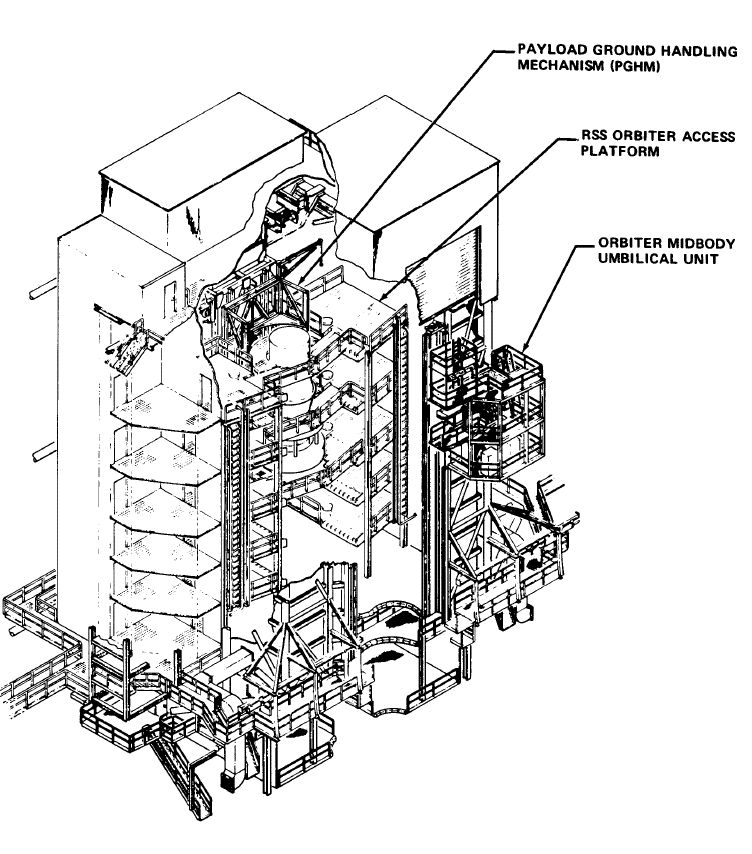
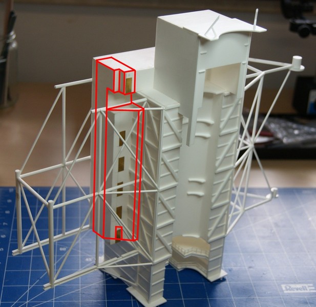
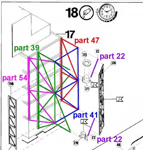
what has always been lacking is the analysis of the right support structure of the RSS, including the Hinge Column to the FSS, with whom I have engaged myself in some detail. And as I have already suggested, this looks similar to those on the left with regard to undersized profiles. ![]()
This involves first of all the parts 22, 39, 41, 47 and 54 shown in Revell’s assembly guide.
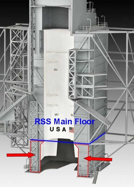
And now I have noticed that the lower side parts of the front elevation below the RSS Main Floor are open to the fore, and not closed as in the Revell-RSS. ![]()
That looks here for the STS-6 at least so, as if these two platforms are open towards the front. ![]()
Source: retrospaceimages.com (STS-6)
Therefore this one must be taken under a closer look. ![]()
![]()
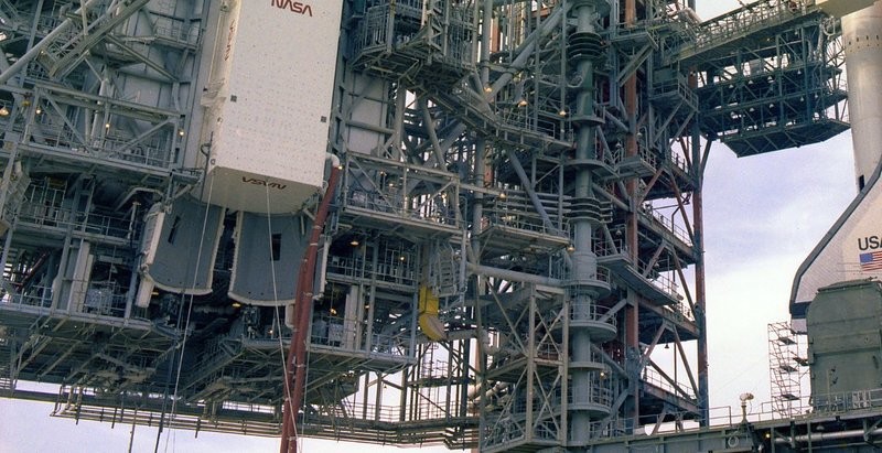
Hello everybody,
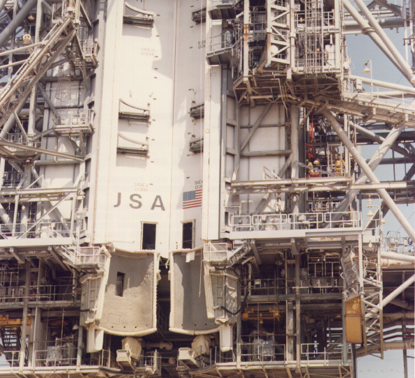
as you can see relatively well in this photo from 1983, the upper floor (APU Servicing Platform) extends deeper into the inside than the front wall as well as the subjacent APS Servicing Platform below the RSS Main Floor of the PCR.
Unfortunately, the middle area is covered by the two OMS Pod Covers. 
And both floors are also much wider than the PCR, which is not also true at Revell, and need to be broadened accordingly. ![]()
In any case, both floors are open towards the front, so one must remove the side panels of the front wall. And consequently, the LVM parts have to be adjusted with the railings, which form the front end.
Another problem are the two OMS Pod Covers below the PCR Bay that are highly abstracted by Revell and sit too far inside, namely where the two APU and APS Servicing Platforms are.
Both Revell parts can, if at all, only as an outer shell to be used, because towards the front or on the inside the Pod Covers have indeed an approximately semicircular shell shape which is adapted to the contours of the OSM Pods.
Here one can see the installation of the OMS Pod Covers, how Revell has imagined, but which is not correct.
As noted above, the red marked front sides below the RSS Main Floor must be removed which then allow a view into the interior of the APU and APS Servicing Platforms.
As can be seen on the very first image, the upper front edge of the pod cover is not flush with the PCR main doors but is significantly more forward on. Presumably, the rear edges will be flush. 
The upper connection of the OMS Pod Covers to the PCR Bay, one can clearly see from this HiRes. photo of STS-1.
And it is true, as I suspected it, because the Pod Covers sit completely in front of the RSS Main Doors, so also this detail would be clarified.
And this was the back of a real Pod Cover, which were mounted on the Pad 39B, and I mean it might be the left cover.
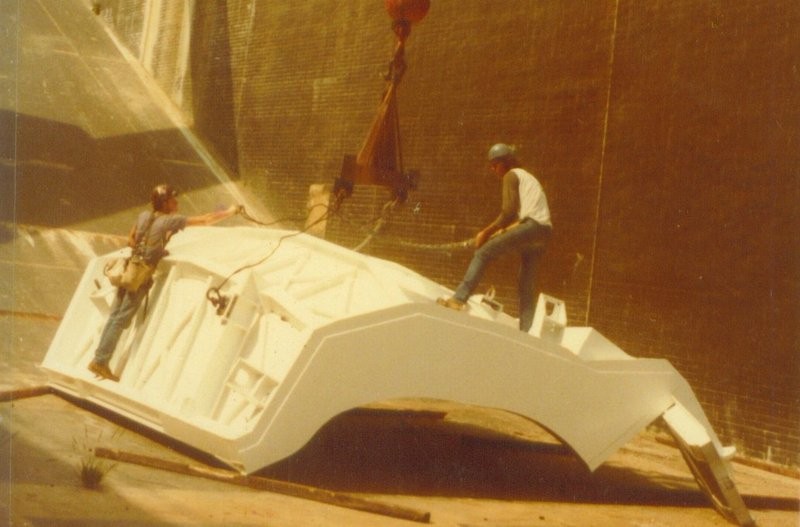
Source: forum.nasaspaceflight.com (J. MacLaren)
A photo of the inside structure would be interesting, of course, but unfortunately I have no HiRes images.
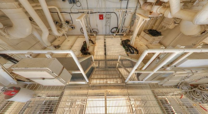
What is interesting is the structure of the two missing platforms that need to be completely scratch built. ![]()
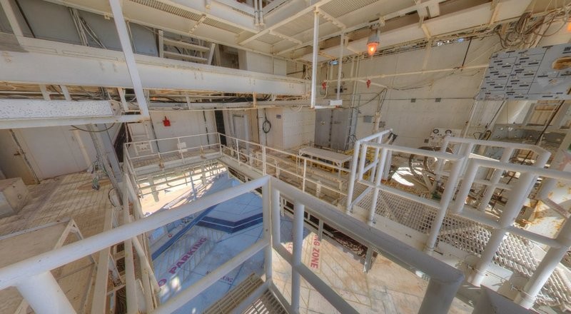
In the meantime, I have found two NASA panorama images that show both platforms in detail and thus constitute a great help. 
And so it looks on the lower APS Servicing Platform, which has a large cutout for the orbiter tail in the middle that extends close to the PCR back wall.
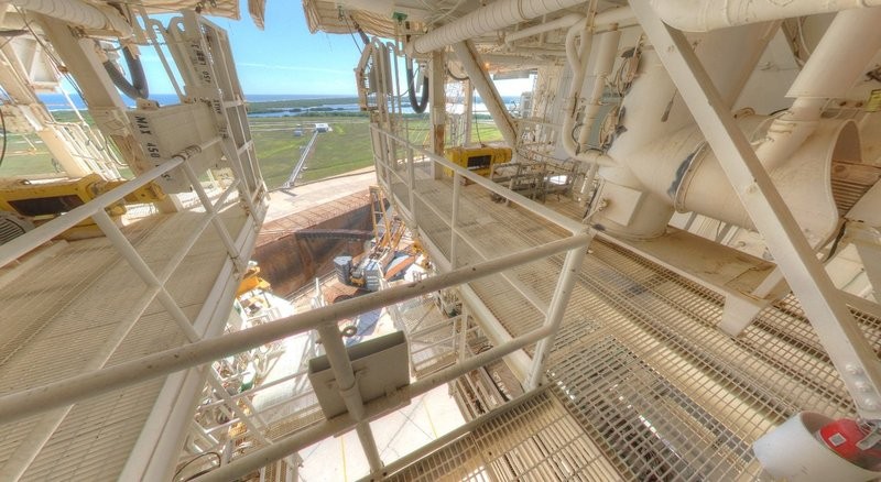
As can be seen on the panorama, the back ceiling of the platform hangs a bit deeper, which can clearly be seen in the next panorama of the APU Servicing Platform .
But look around to your heart’s content. ![]()
And so now the structure of the two platforms looks relatively clear, which is but a tricky challenge for scratch building.
But as we should know, nothing is impossible.
![]()