Hello everybody,
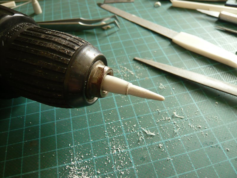
after the weekend it will now go on with the Rainbirds. Because I did not immediately want to continue with the “Cartridge belts” and have needed some change, I have intensively considered the central Rain Bird A-1 with the four cute flange tubes and thought how I could possibly scratch it. 
On most images one can see only revision openings on the flange tubes, which are closed with 12 screws,

Source: NASA
but in a photo stream of Andrew Scheer I have found a photo in the opened state. 
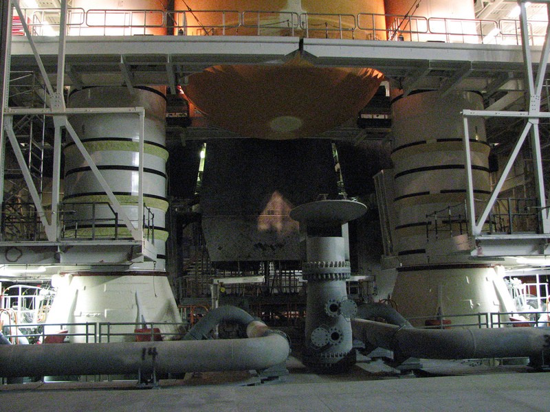
Source: flickr.com (Andrew Scheer)
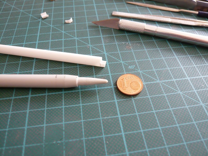
A somewhat bold idea I have had already.  But in order to test this, one needs the dimensions of the parts, which are the flange tube with the covers and bolts and a corresponding 1:1 sketch.
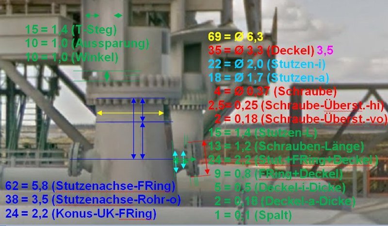
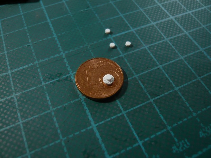
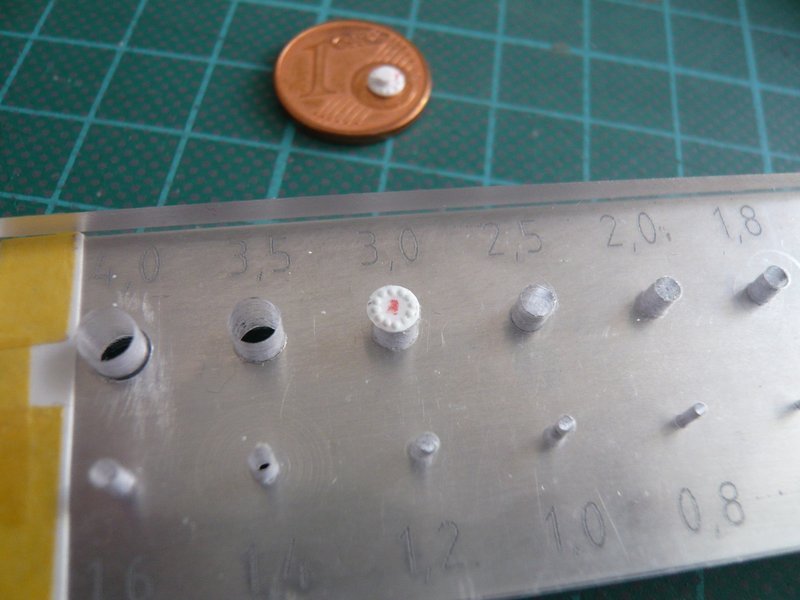
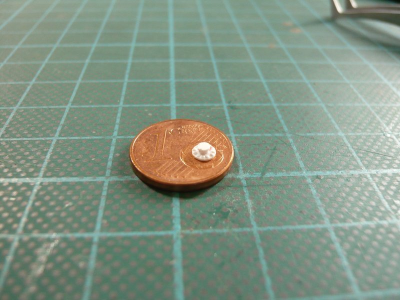
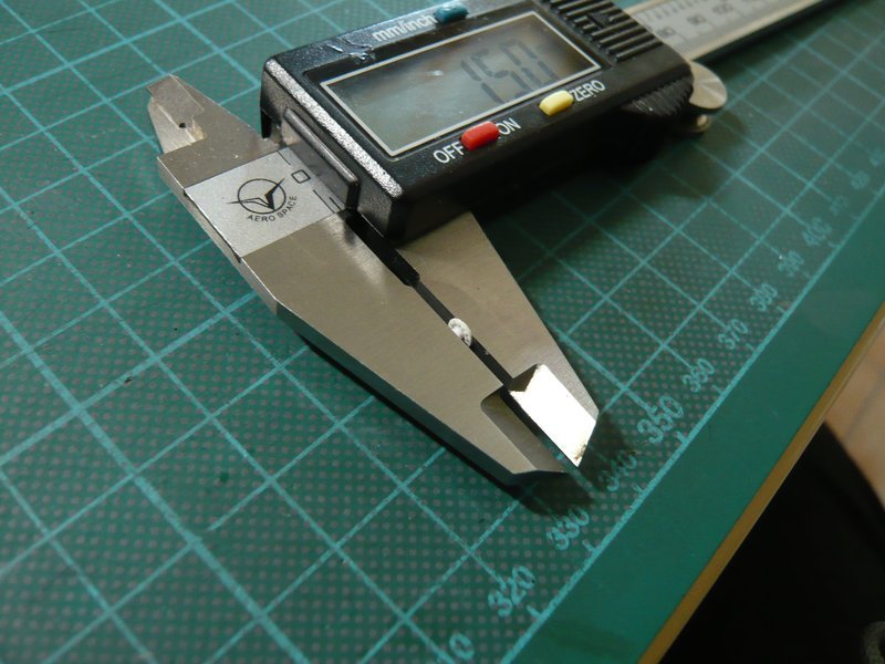
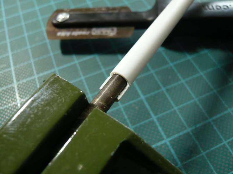
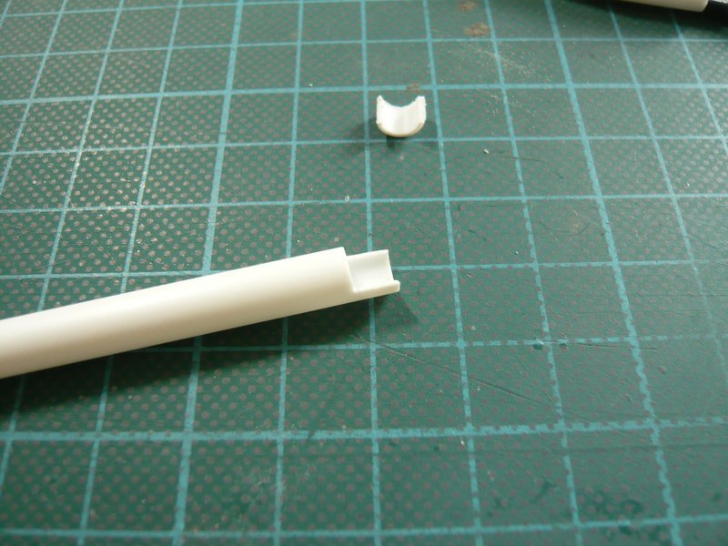
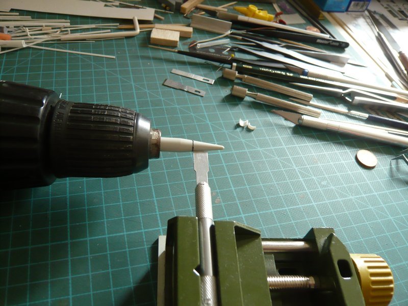
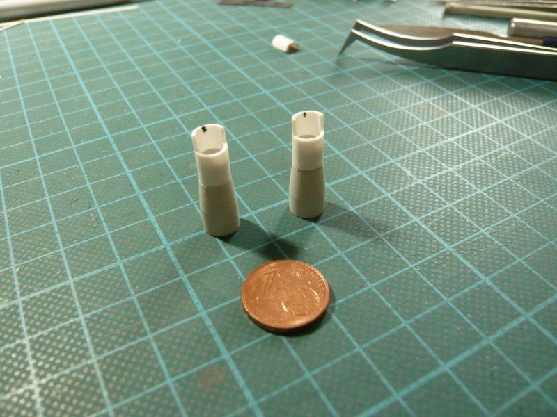
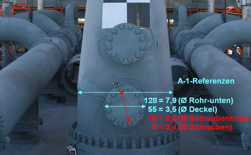
The size of the flange and cover can be relatively easily determined from frontal shots like this, by using the diameter of the lower tube with Ø 7,9 mm as reference, which would be approx. 3,5 mm. For that I can use my Punch & Die Set again.
This results in a diameter of the bolt circle of Ø 2,9 mm and for screws Ø 0,4mm, which already shows how tiny these parts would be again. 
Source: NASA
Somewhat more difficult it is with appropriate images, where one can see the lateral structure of these flange tubes undistorted for determination of the dimensions. Since most photos, such as the first image above, show the Rainbird more or less from oblique perspectives, these photos can not be used unfortunately. But in a NASA streetview panorama I have found a usable lateral view and so I was able to determine the length of the flange tube as well as the thickness of the flange and cover, and the gap between them, inclusive the screw length. 

Source: NASA
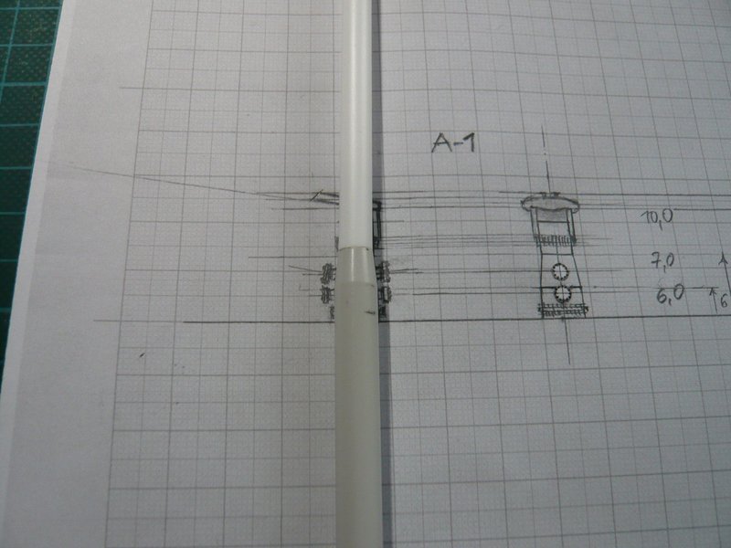
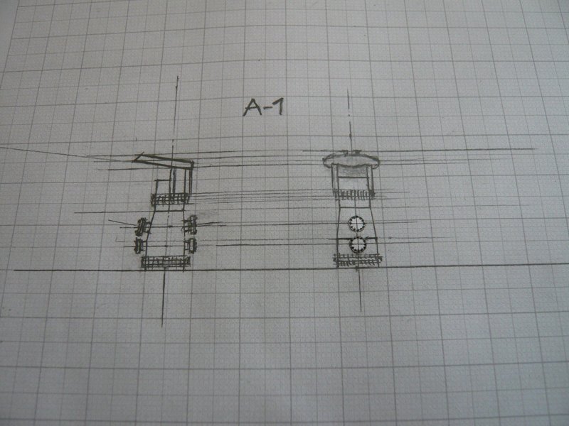
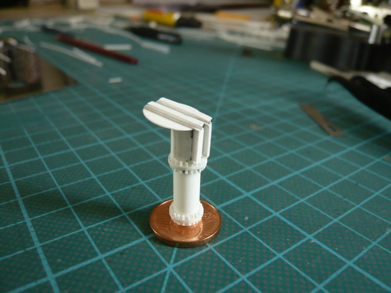
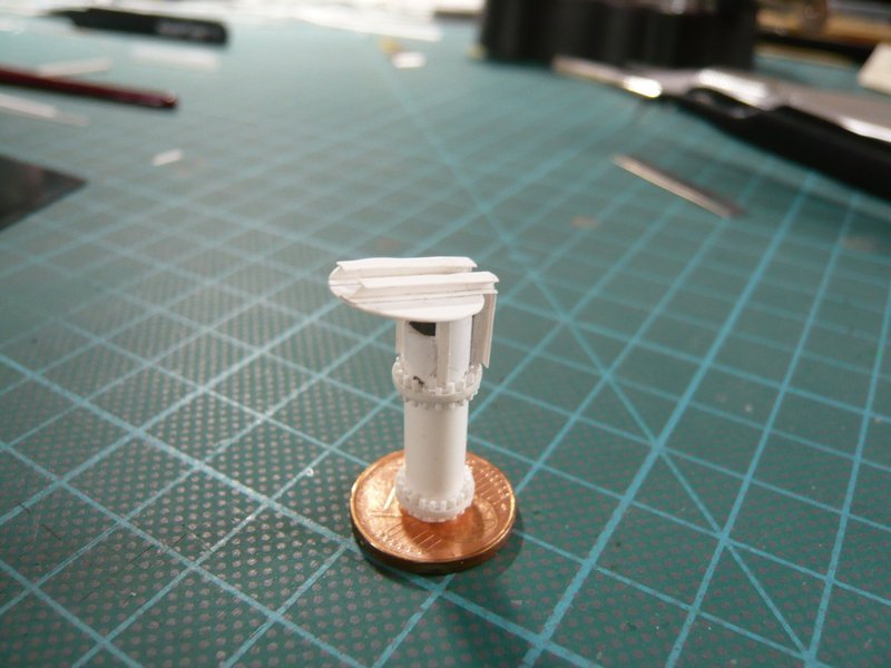
So I have drawn this sketch (1:1), where the bird A-1 already looks a lot smaller than on the pictures. 
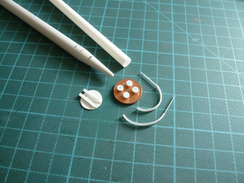
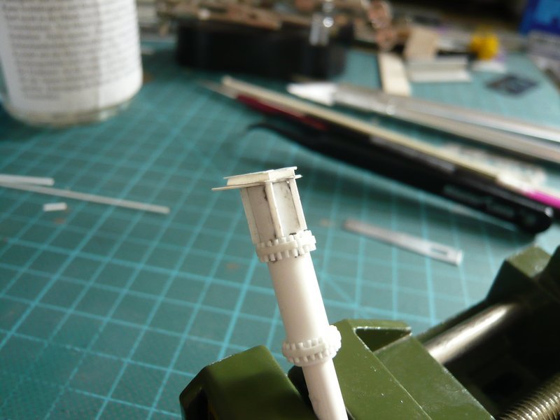
And now to the flange with cover and 12 screws and my conception for scratch-building these parts. 
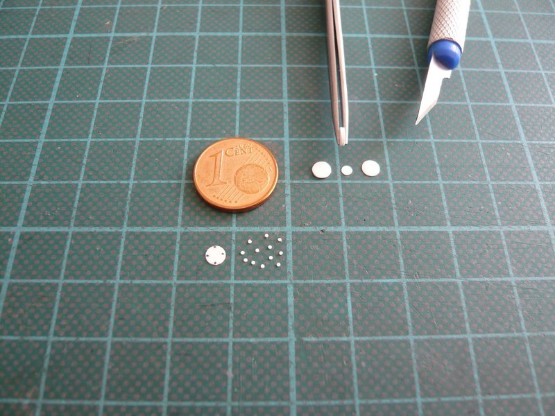
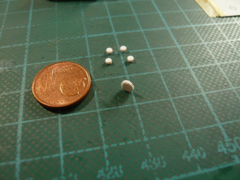
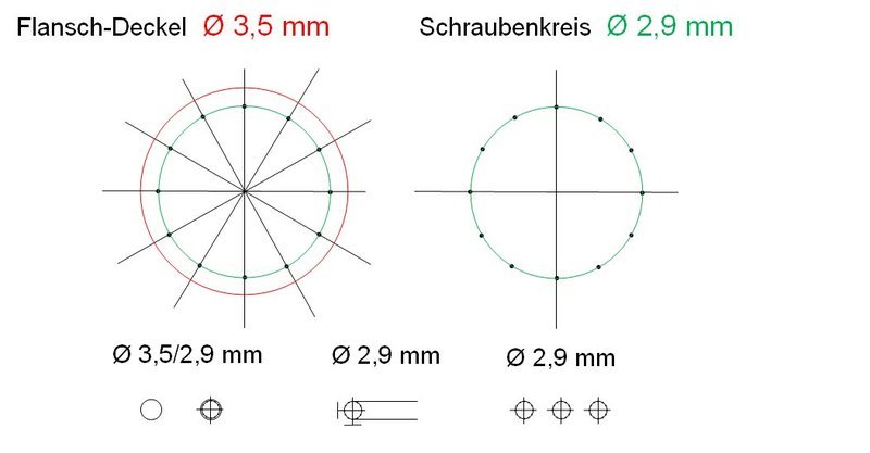
First, I have drawn the layout of the bolts on the flange cover something enlarged, and then this graphic was reduced to Ø 3,5 mm, in which for further procedure actually only the bolt circle (Ø 2,9 mm) is important. From this bolt circle I wanted to create me a transparent mask for transmitting the positions of the 12 screws onto the cover (Ø 3,5 mm x 0,2 mm) as well the flange (Ø 3,5 mm x 0,5 mm), in order to drill them out, but the procedure somehow appears to be adventurous, right?  And into the holes of the discs I then wanted to glue the bolts (Ø 0,4 mm) with a little overhang, insofar as to my idea or theory.
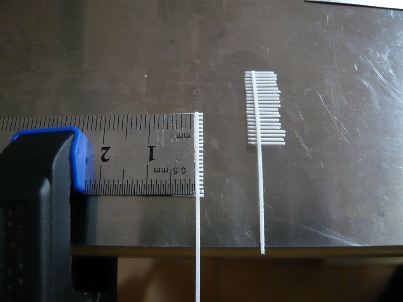
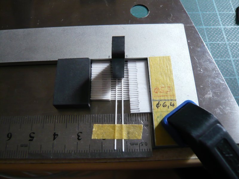
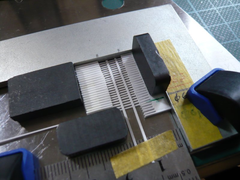
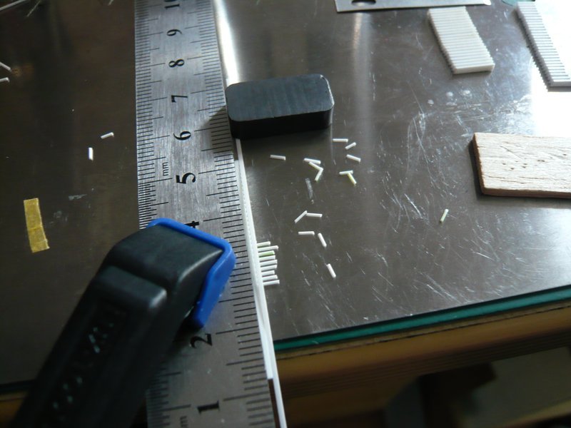
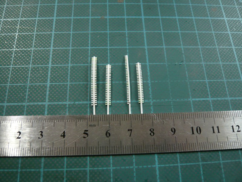
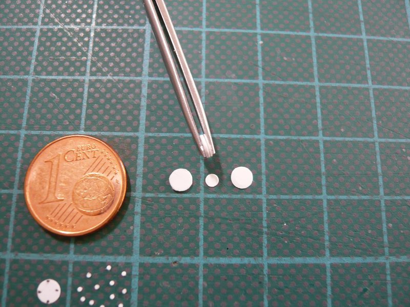
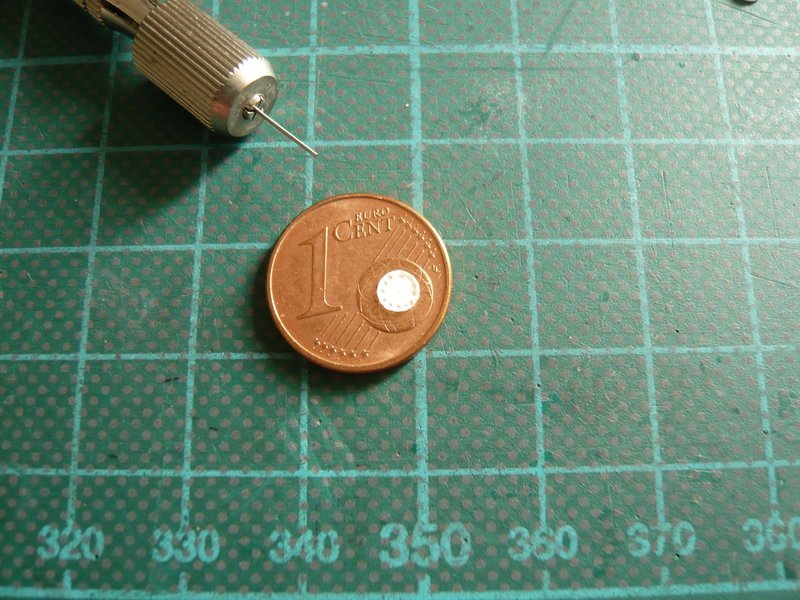
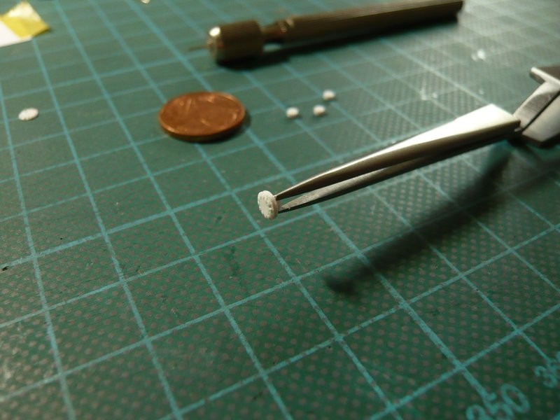
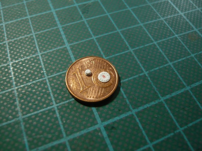
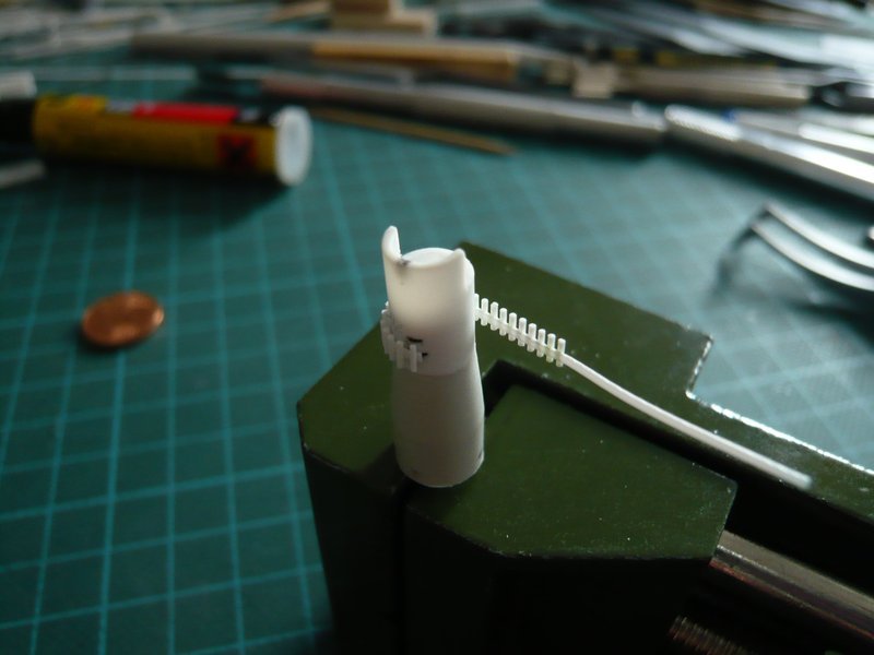
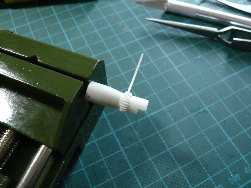
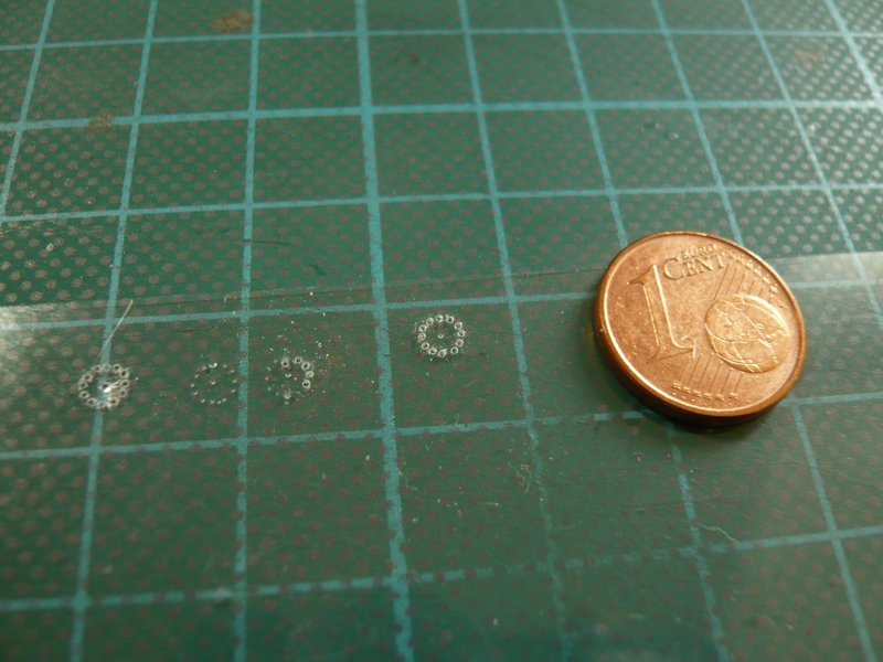
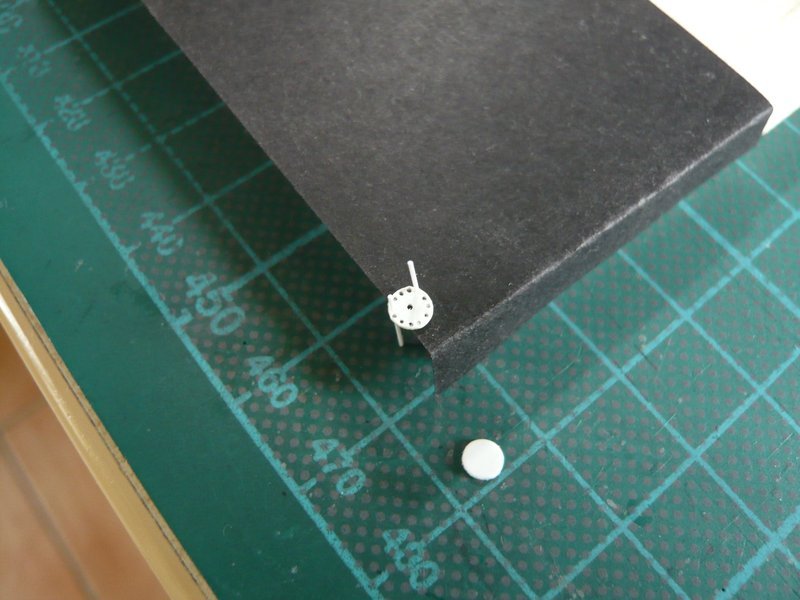
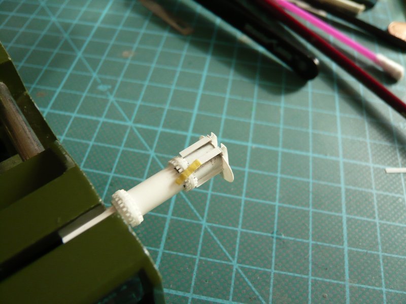
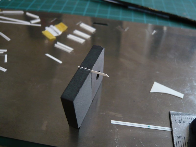
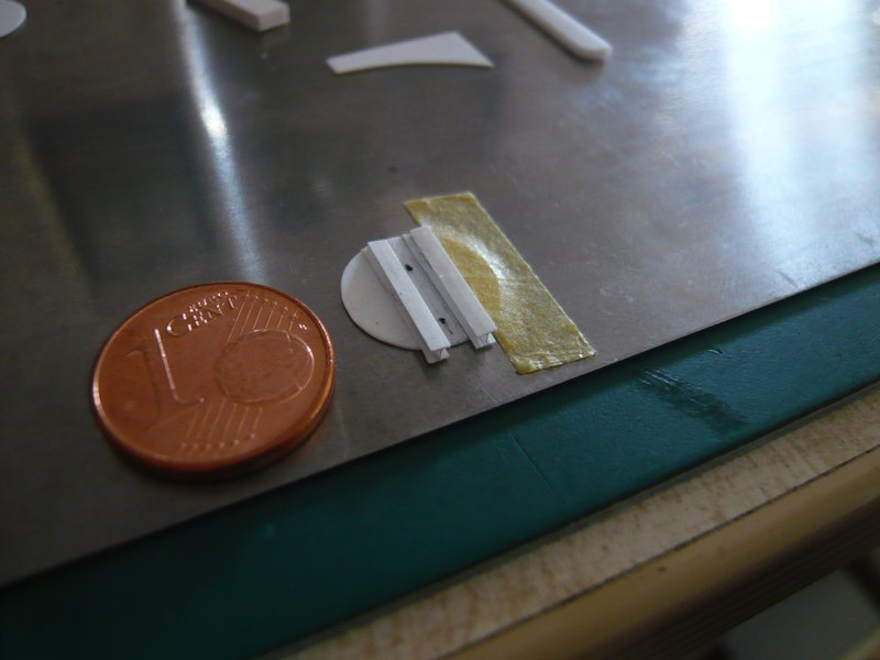
And as I said, so done. The paper template of the bolt circle (Ø 2,9 mm), I have carefully pierced with a needle on a transparent film and then drilled with a drill (Ø 0,35 mm), which was not easy and less funny and sometimes went wrong.
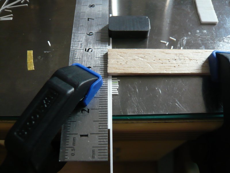
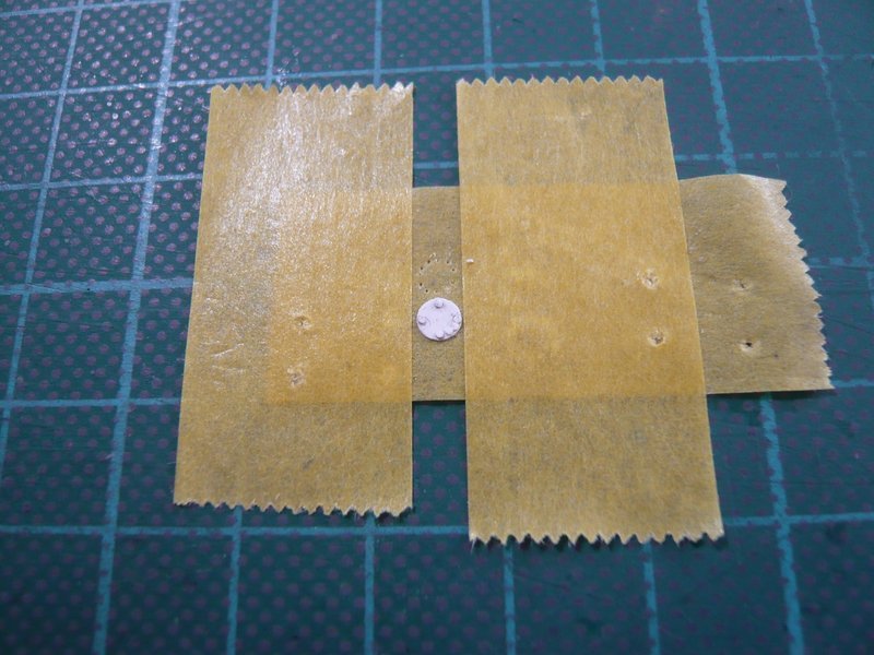
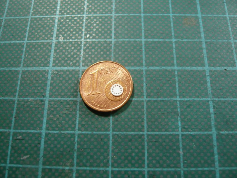
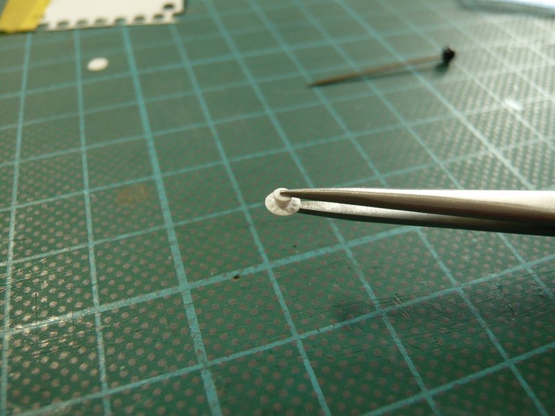
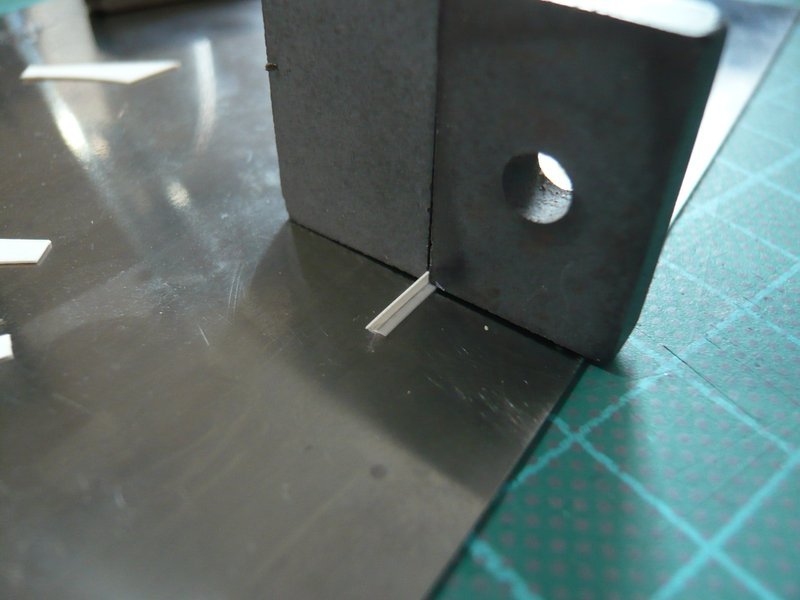
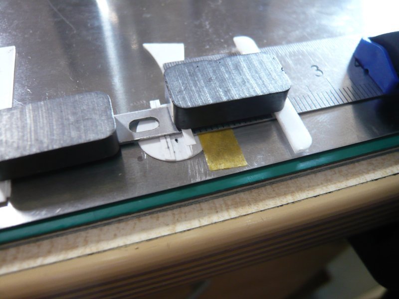
Far more difficult was drilling of the cover with applied template that can easily slip,
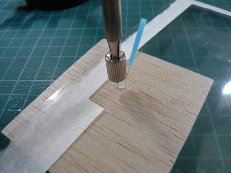
which may lead quickly to excentric bolt circles or waste. 
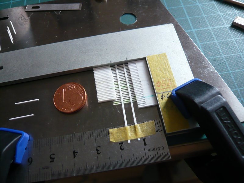
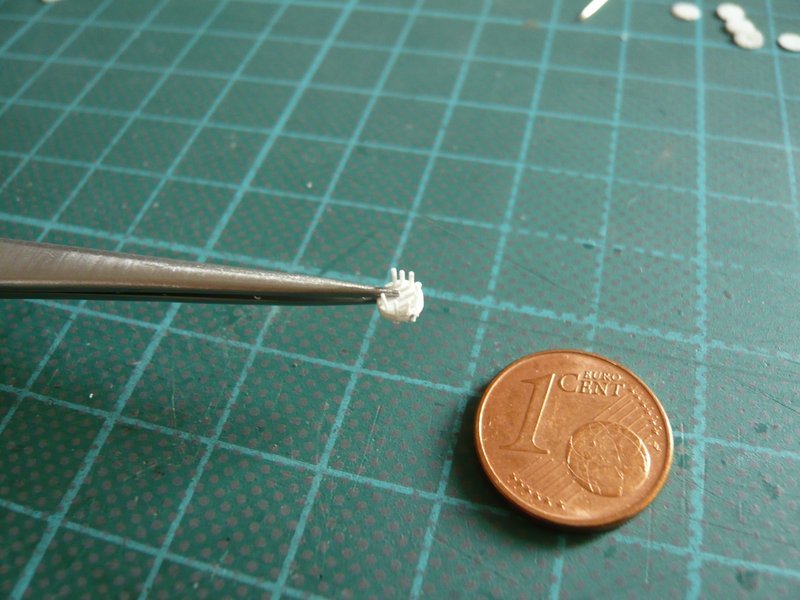
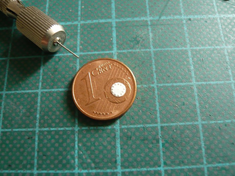
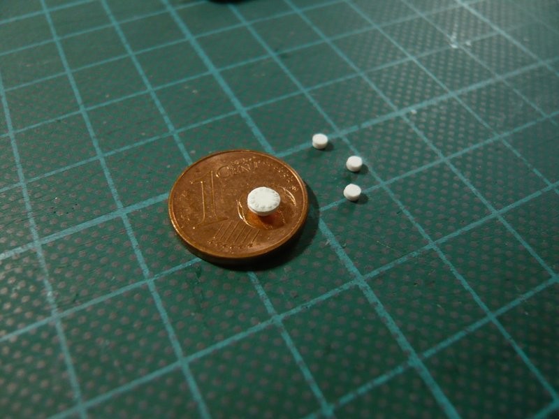
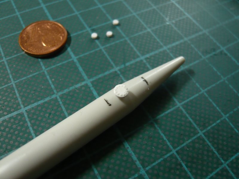
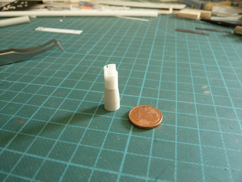
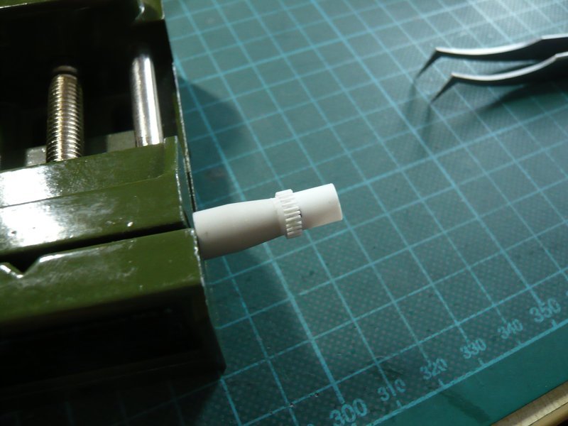
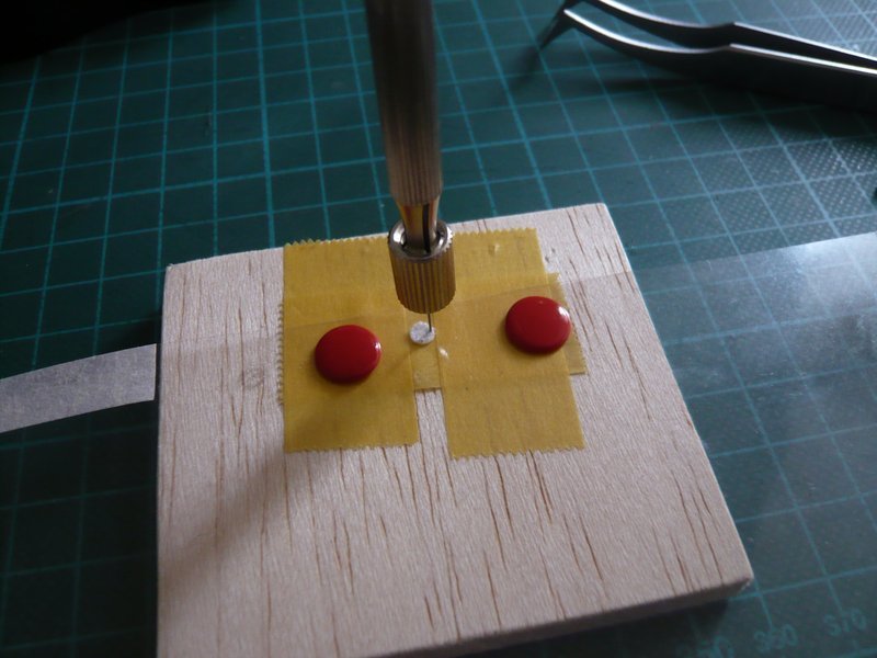
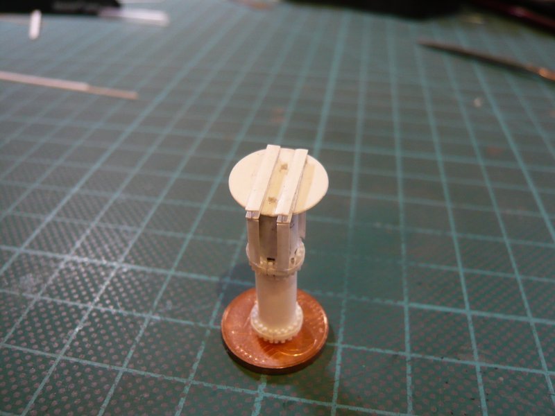
But this cover here is quite well succeeded already. 
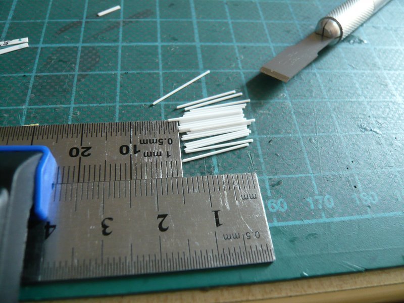
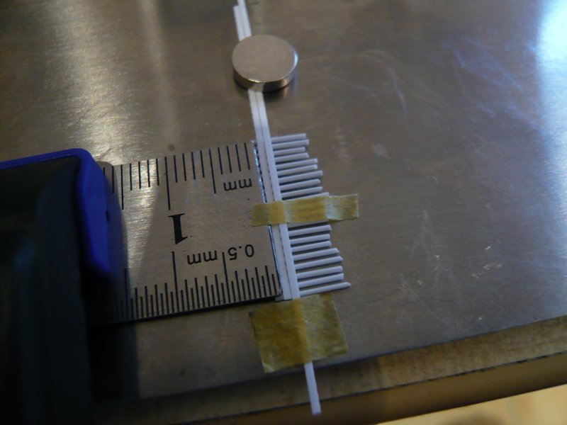
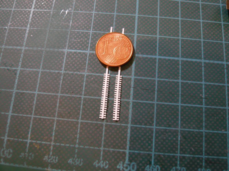
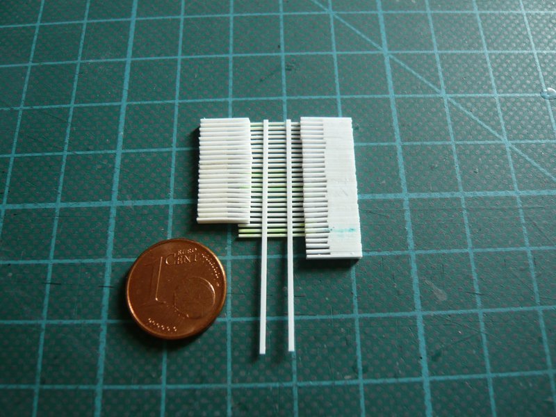
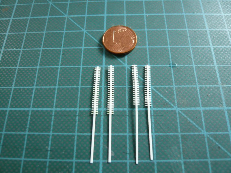
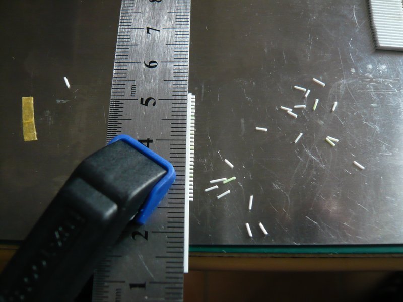
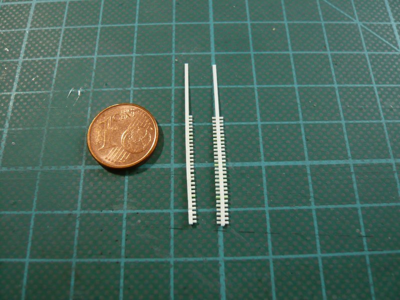
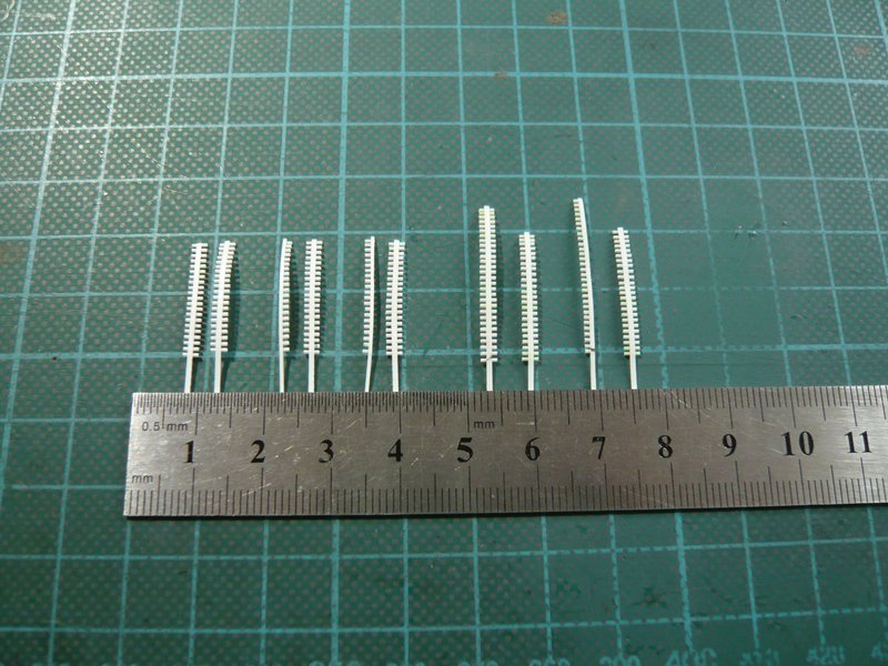
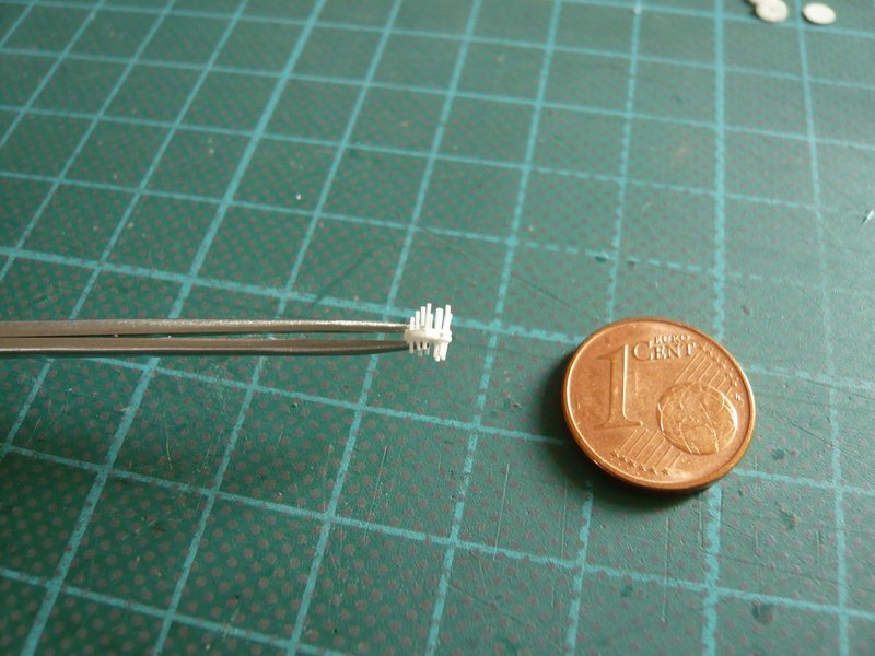
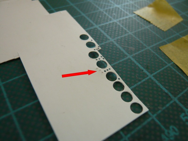
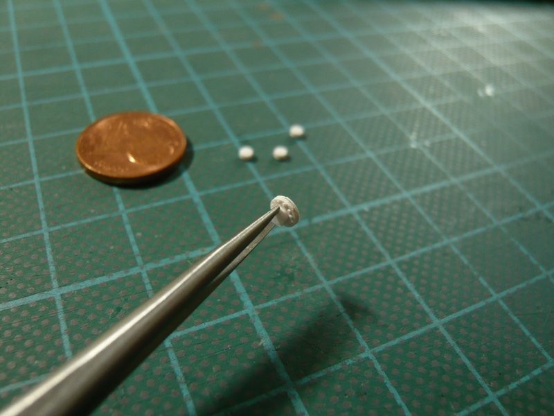
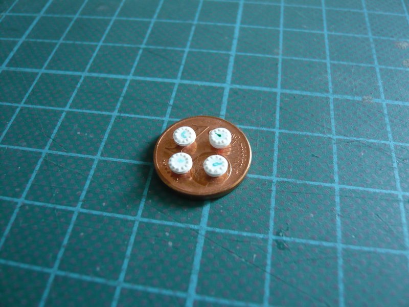
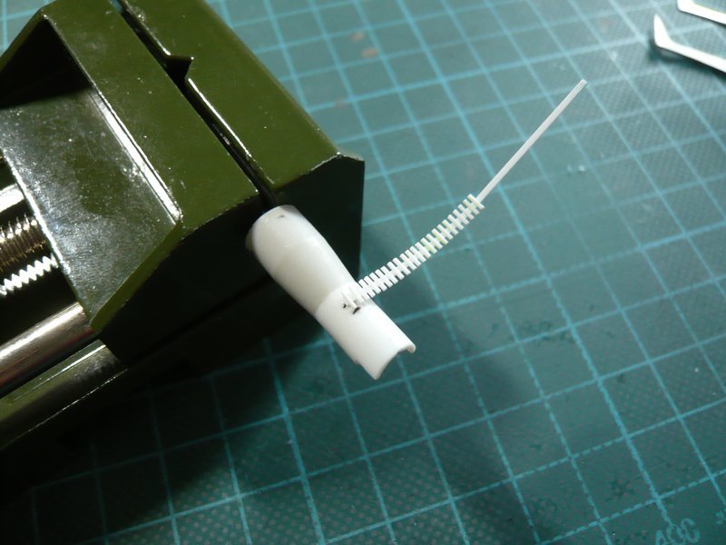
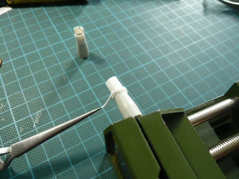
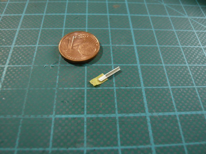
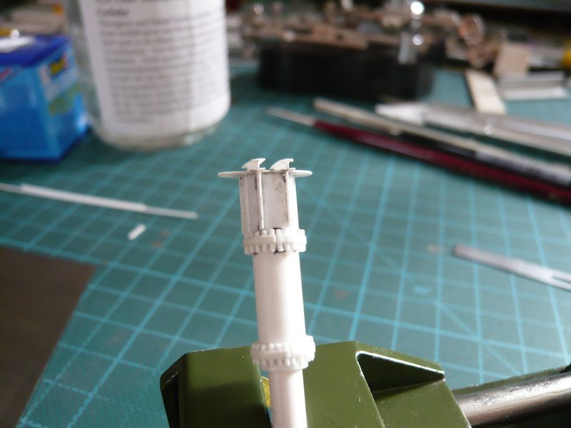
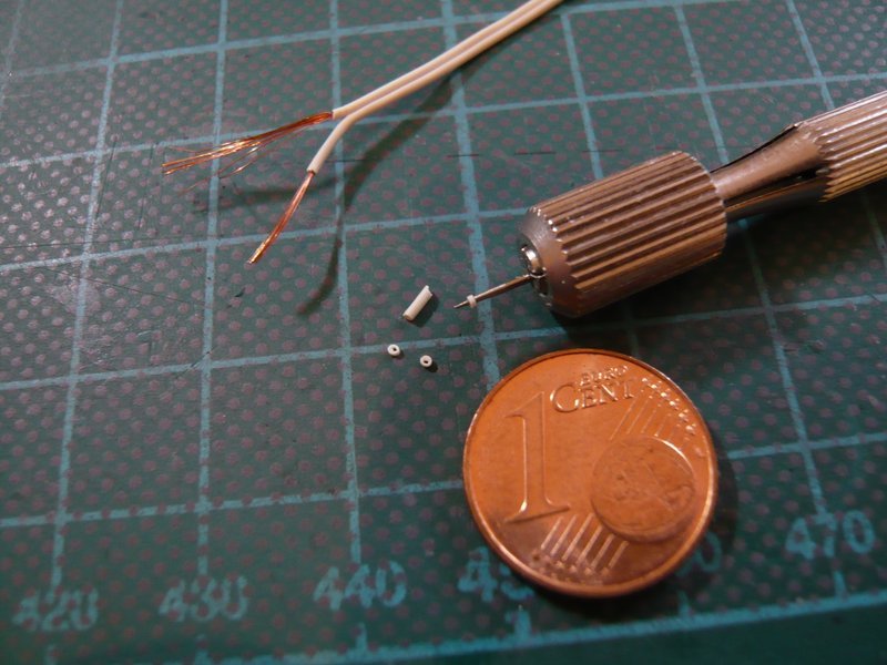
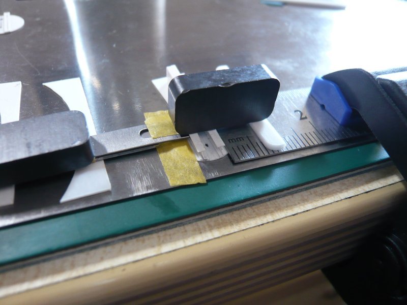
And here I have threaded two small rods Ø 0,3 mm, which unfortunately are somewhat too thin. But there are no rods with Ø 0,4 mm, and for Ø 0,5 mm will probably not be enough space on the 2,9 mm bolt circle. 
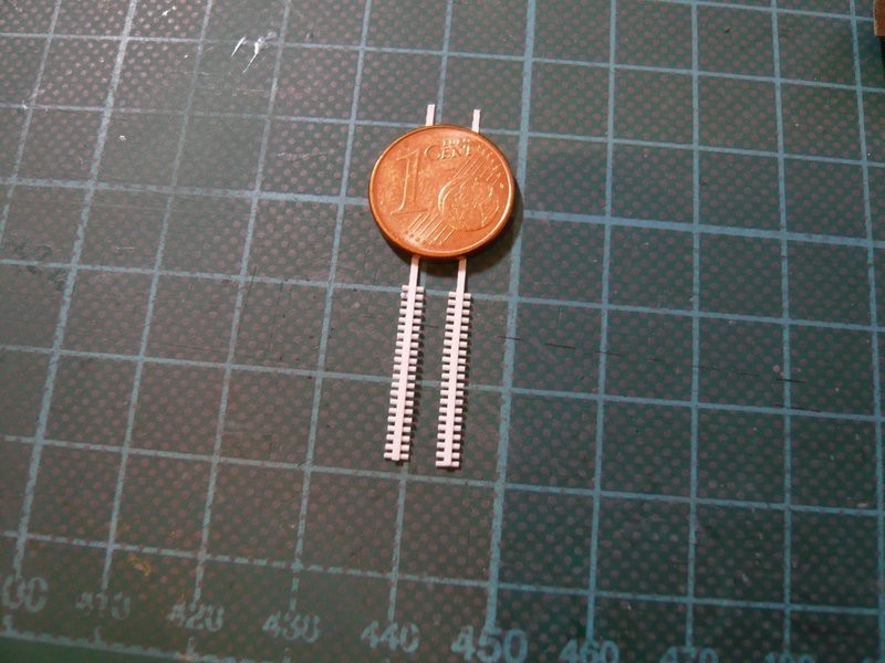
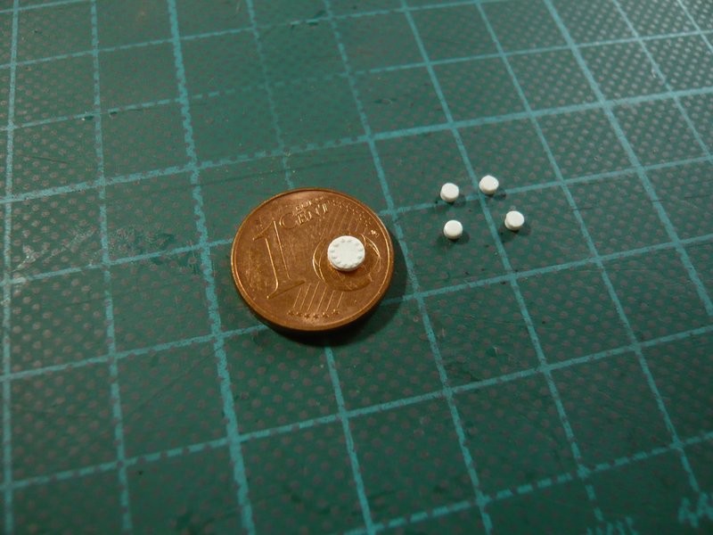
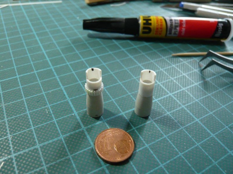
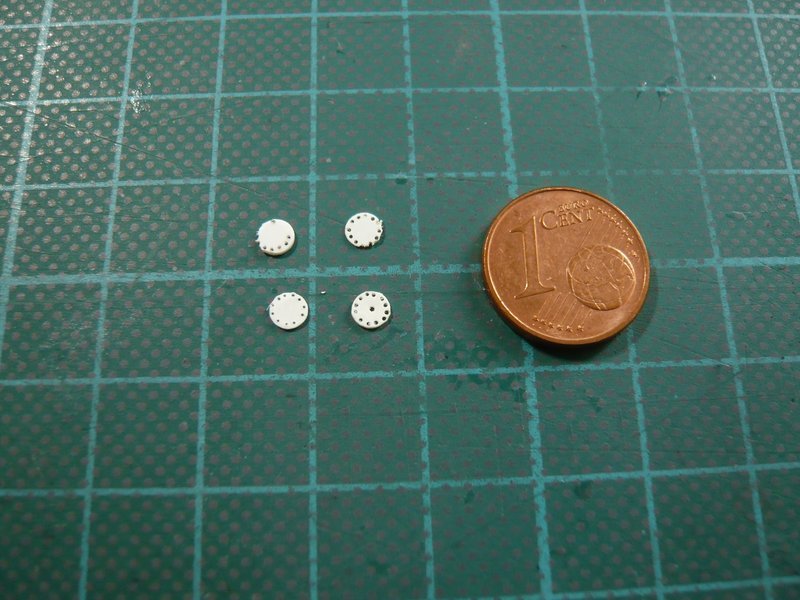
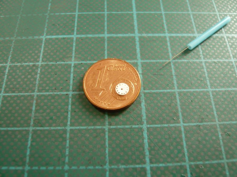
Maybe there are other options too, but for today it should be enough. 

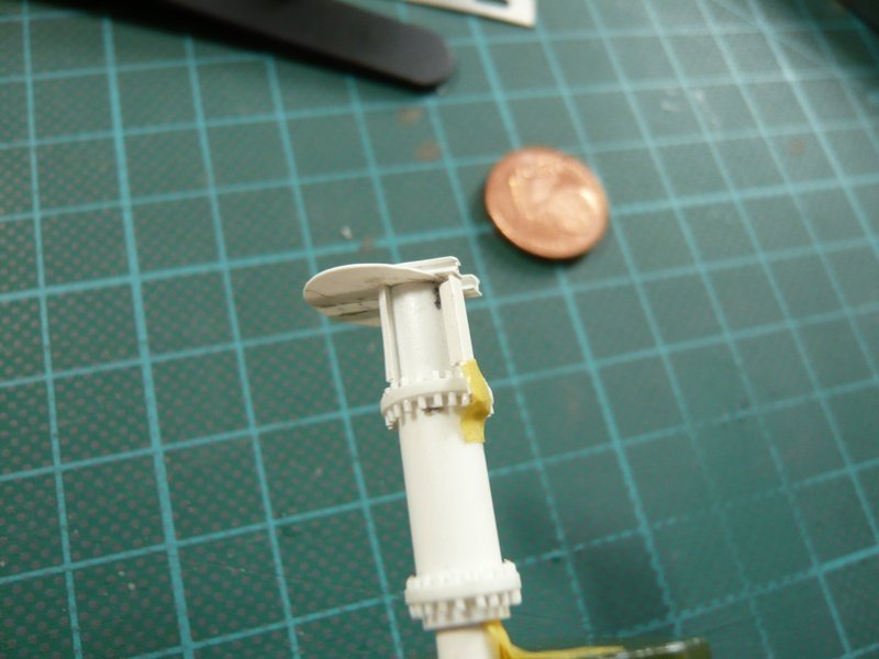
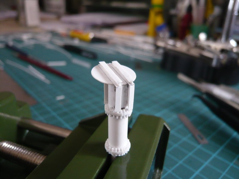
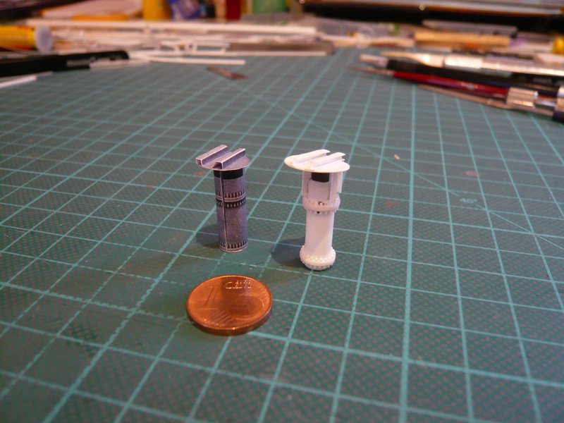


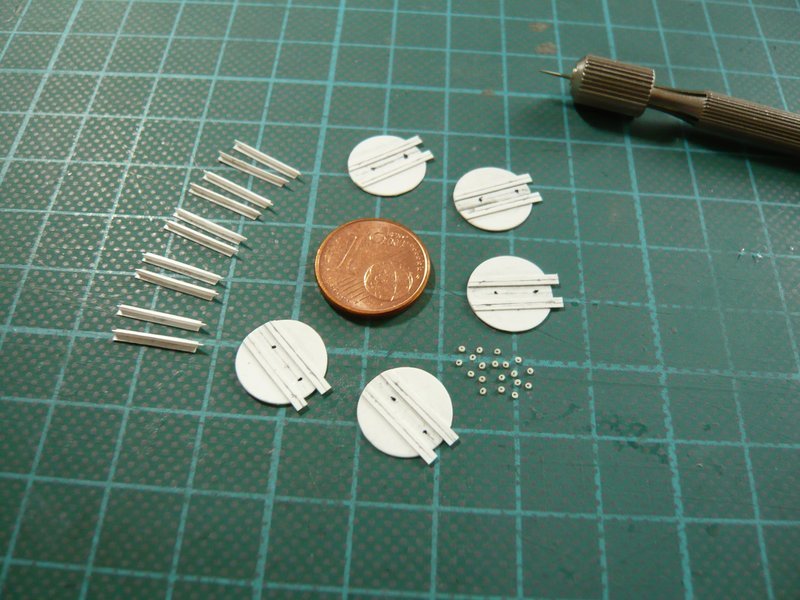
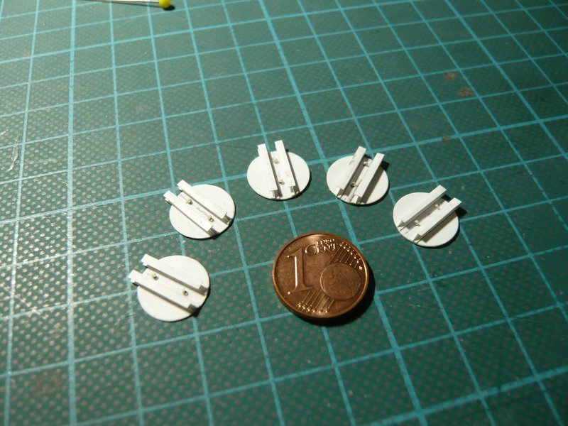
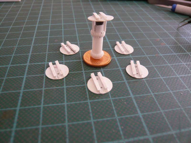
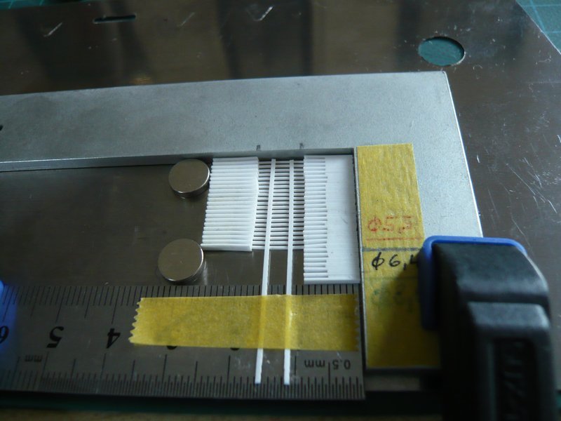
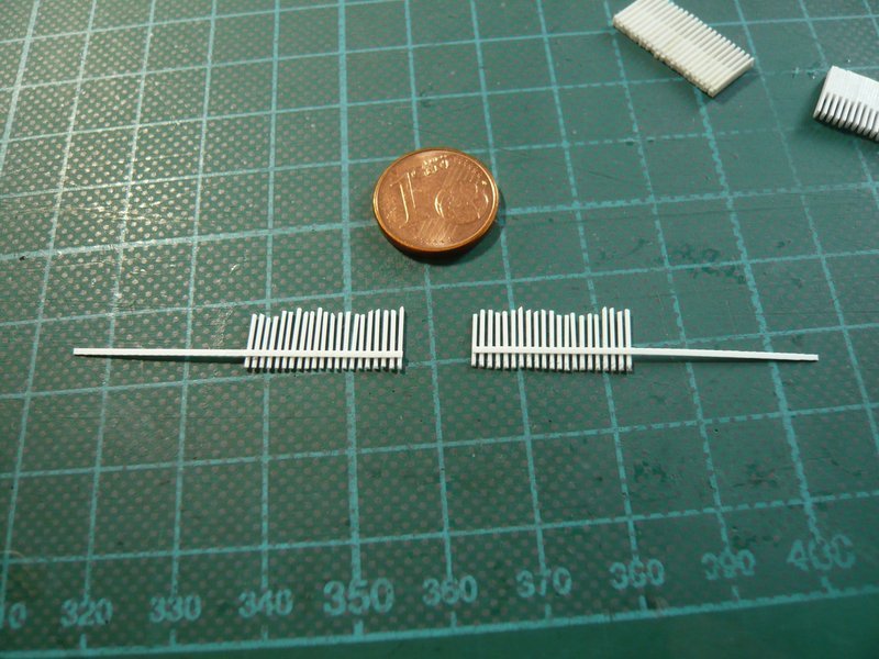
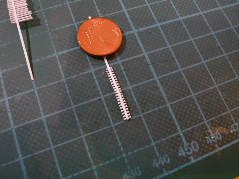
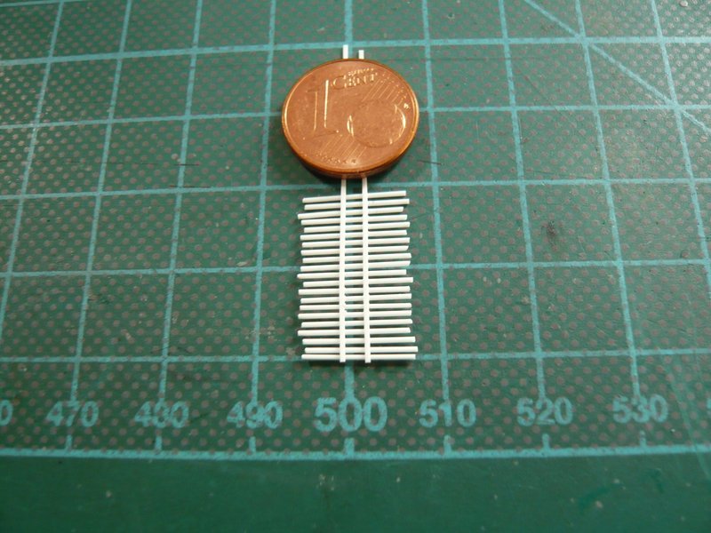
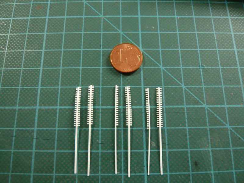
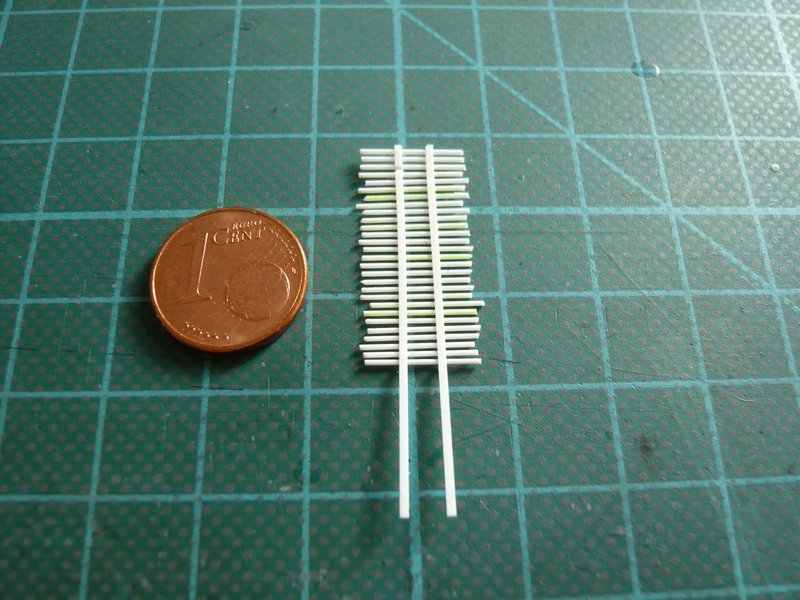
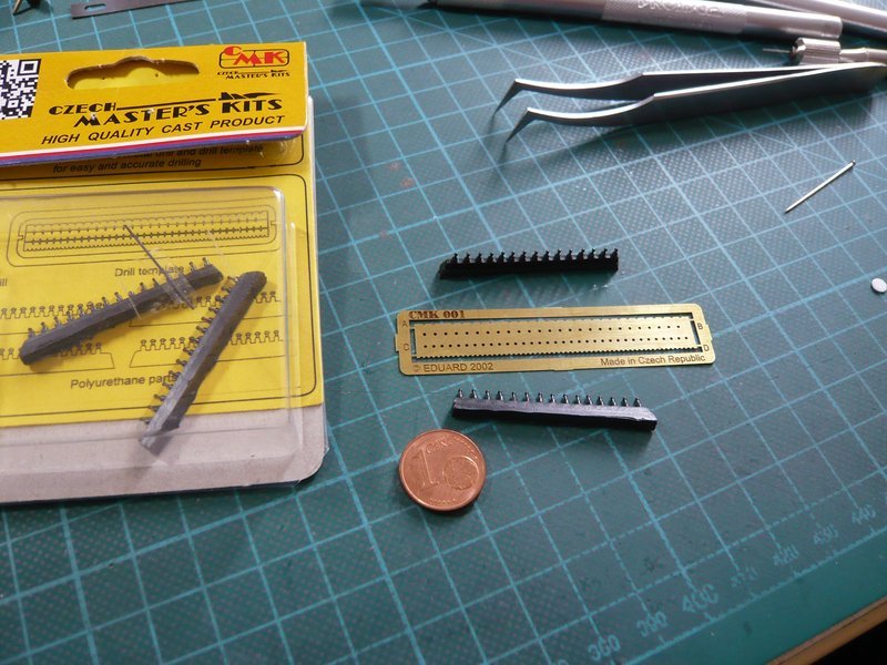
 The ammunition is ready for the next