Space Shuttle Launch Complex 39A with Challenger STS-6 (1:144)

Thanks John for your kind words.

It’s really sad … For 25 years he knew both KSC Launch Pads 39 A & B like the back of his hand.

With his amazing panoramas he brought the stars from the sky for me during his lifetime.

That’s why his website is a true treasure trove for Real Space Modelers like me. It is a detailed compendium of American Space missions for the last 25 years.

R.I.P.

3 Likes

My condolences to you Manfred and prayers for his family and friends. I enjoyed the link to his website you shared with all of us and what an amazing Legacy he has left behind. Those photographs will forever speak loudly of who he was. Now, he is forever a part of the heavenly glory.

2 Likes

Thank you Tank and Mike for your condolences.

In 2000 John began his media career covering rocket launches and various space-related events with Atlantis’ mission STS-106 (09/08/2000). Since then he developed an impressive encyclopedic knowledge of the American Space program. b033.gif

His fantastic 360° panoramas have actually always inspired me anew to look for more details to scratch, which has constantly expanded my experience for scratching craziest things. hmmm.gif

FOREVER REMEMBERED …

2 Likes

Hello friends,

meanwhile I have inquired about John O’Connor’s grave at Riverview Memorial Gardens in Cocoa and a staff member will direct me to it so I can do honour to him during my vacation in October.

FOREVER REMEMBERED …

3 Likes

Hello friends,

after a long and exhausting search through my previous build report, I found the last post before my Florida trip last October, which was in May 2023 (401/44), which was about the Rainbirds.


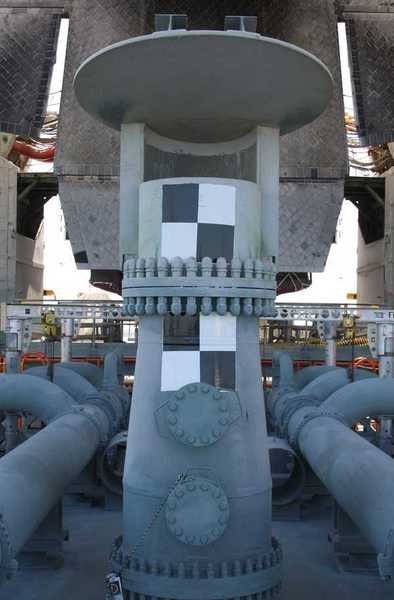
Source: nasatech.net

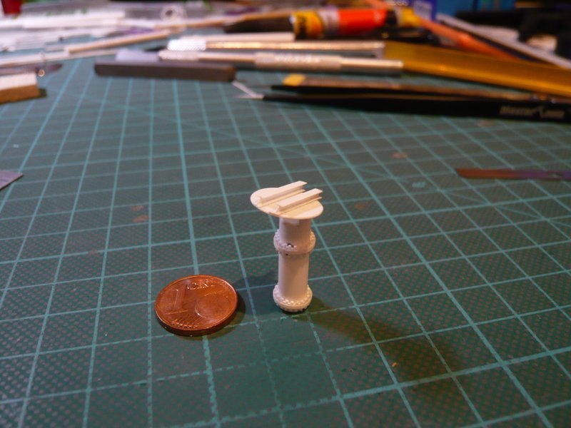
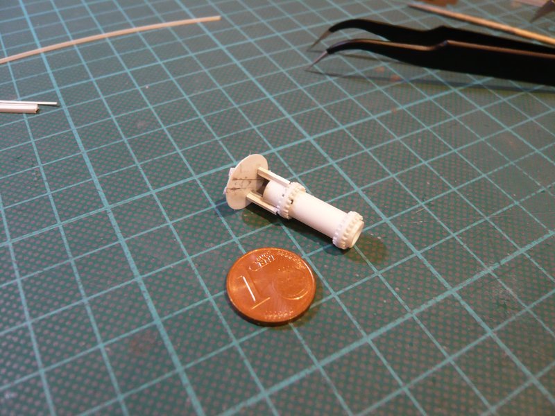
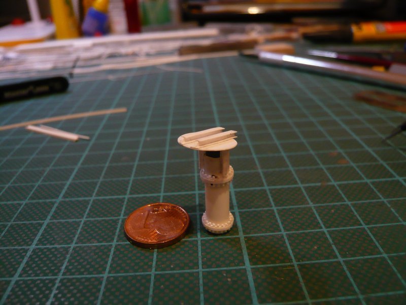
Now only a pipe with Ø 6,3 mm must then be fitted with the wide opening and cover, and the shell construction is finished, that could work.

And at this point we can now continue. I hope that it is in the sense of all and that you are still interested in it.

Hello everybody,

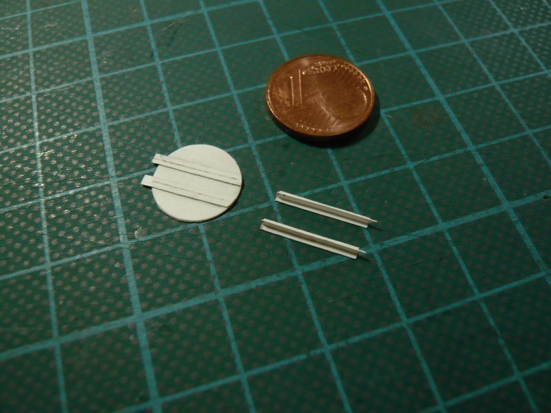
yep, finding the knitting needle was really a stroke of luck, because thus I need only two parts for the tube, because the transition to the conical central part already exists, and can thus save me some work. But just in case I had already set aside some marker pens (Ø 8 mm).

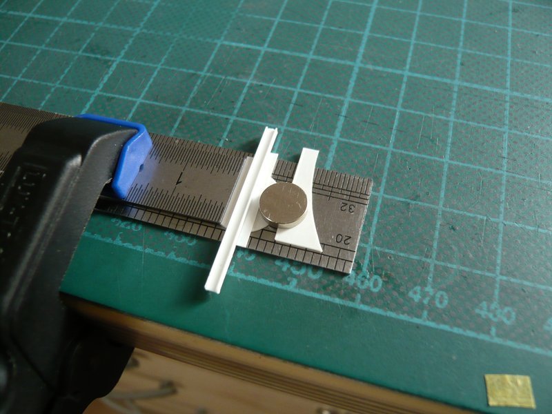
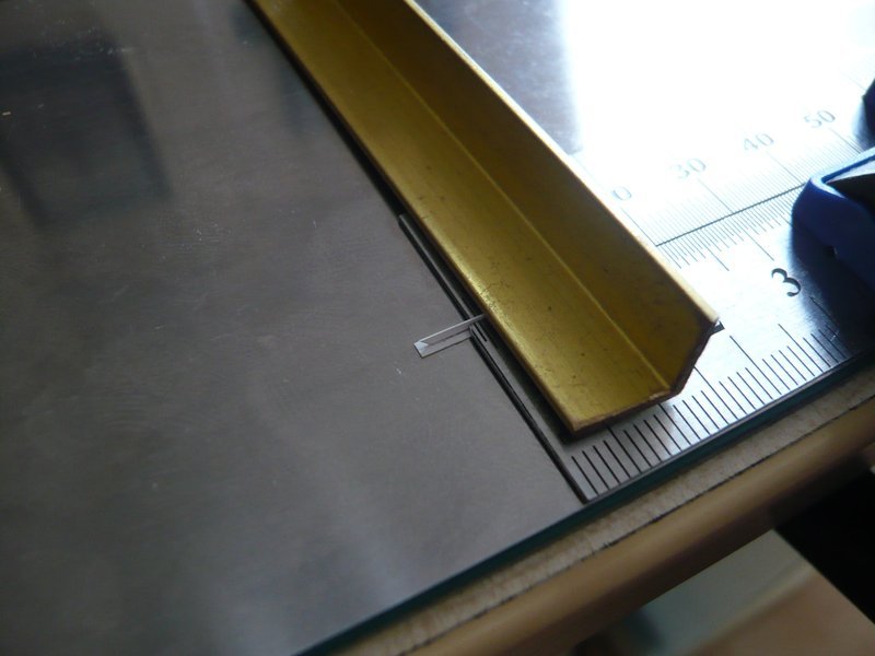
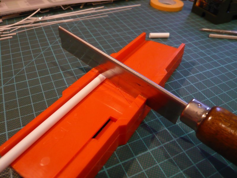
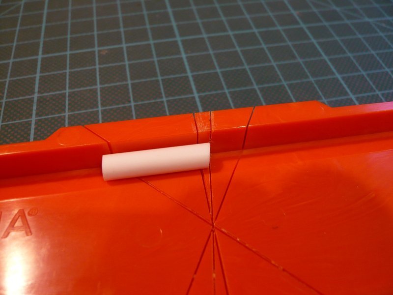
Then I further thought about to improve the cutting of the bevels for the cover plates. For this I’ve cut a separate 8° cut in my miter-device what sawing makes something easier as with my auxiliary device. That could occur to me even before.

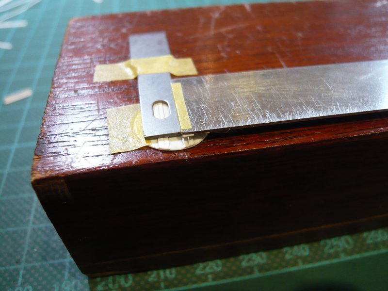
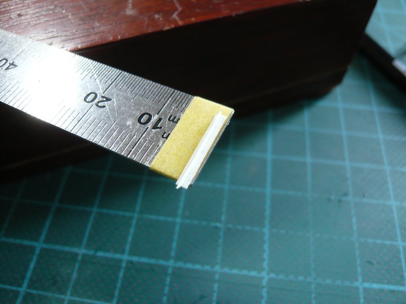
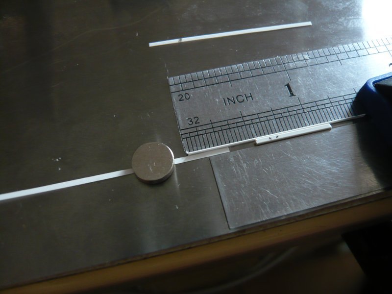
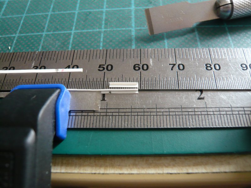
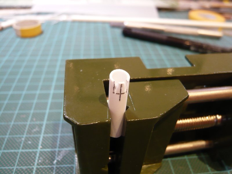
And for marking out and sawing of the openings I have also been thinking a better solution. For that I have marked the opening of a tape and glued to the tube.

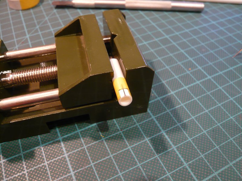
And for the sawing of the opening I have used my Dremel with the small circular saw,

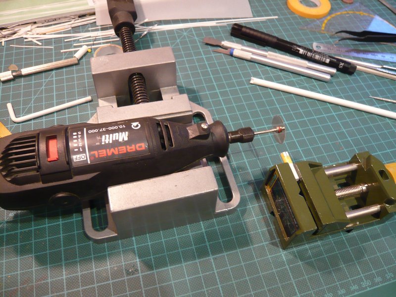
because the openings so should certainly become more accurate, I hope.

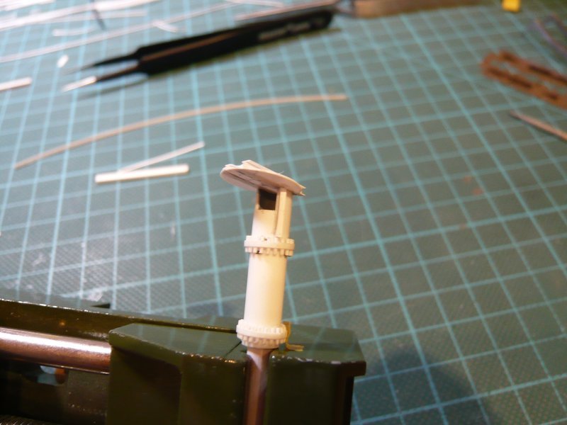
That was a surprise when I’ve realized that I had sawed the opening at the bottom of the beveling instead of at the top, what nobody has noticed so far.

And that was also the reason for further pretests.

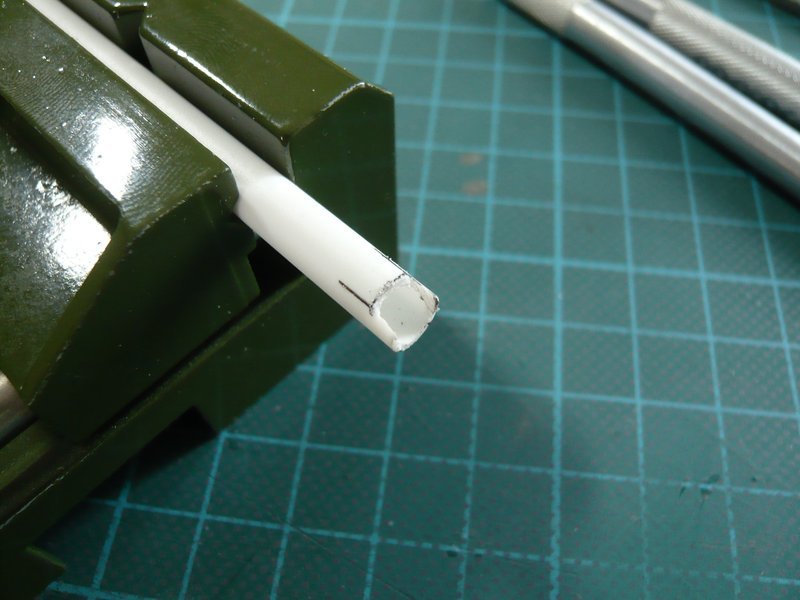
Here again first with the mini circular saw, but without having sawed the beveling previously.

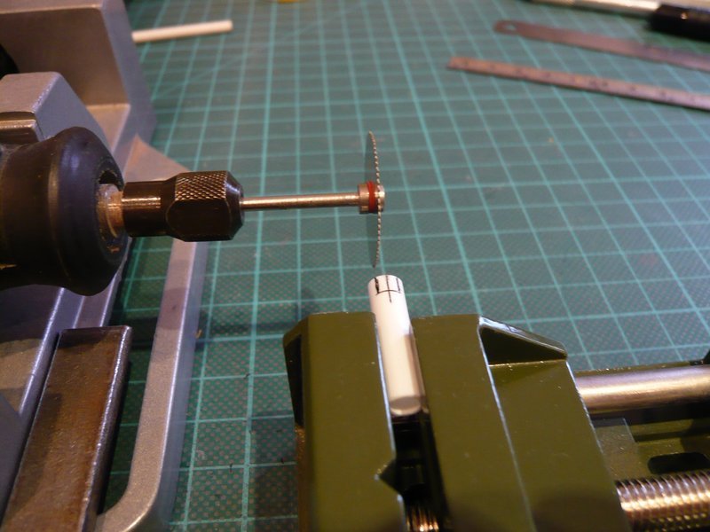
But thereby the markings can also quickly be exceeded,

or else be cut as here in another test into the side wall.

In any case one must still rework the opening,

whereby this also can become wider and higher than desirable.

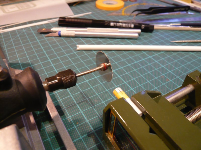
The height can be adapted by making the cut for the beveling a little bit further below. But all in all I’m still not completely satisfied with the results of the saw method, especially as I have also noticed that probably the spindle or the clamping sleeve of my Dremel has a slight blow which is transmitted to the saw blade.

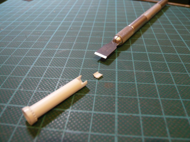
That’s why I tried yet another method, where far fewer swarfs arise, and therefore seems to me much more sympathetic.

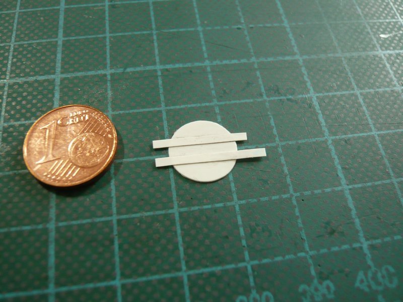
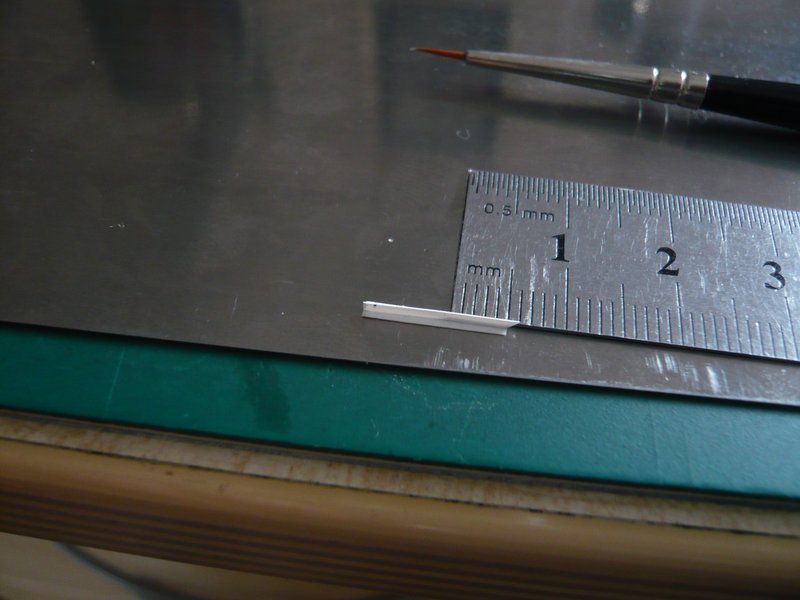
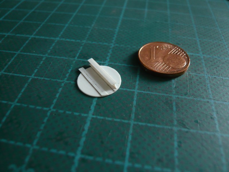
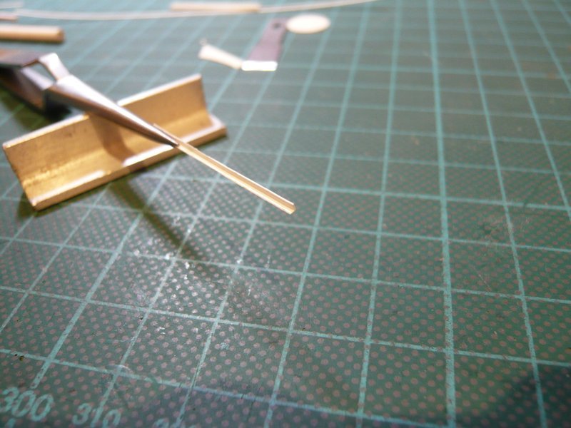
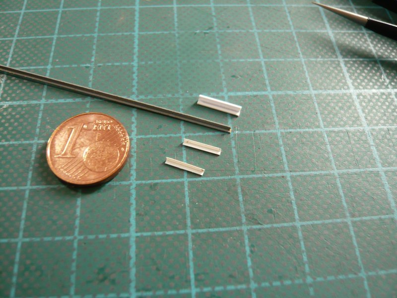
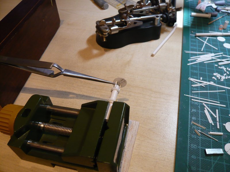
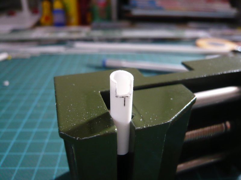
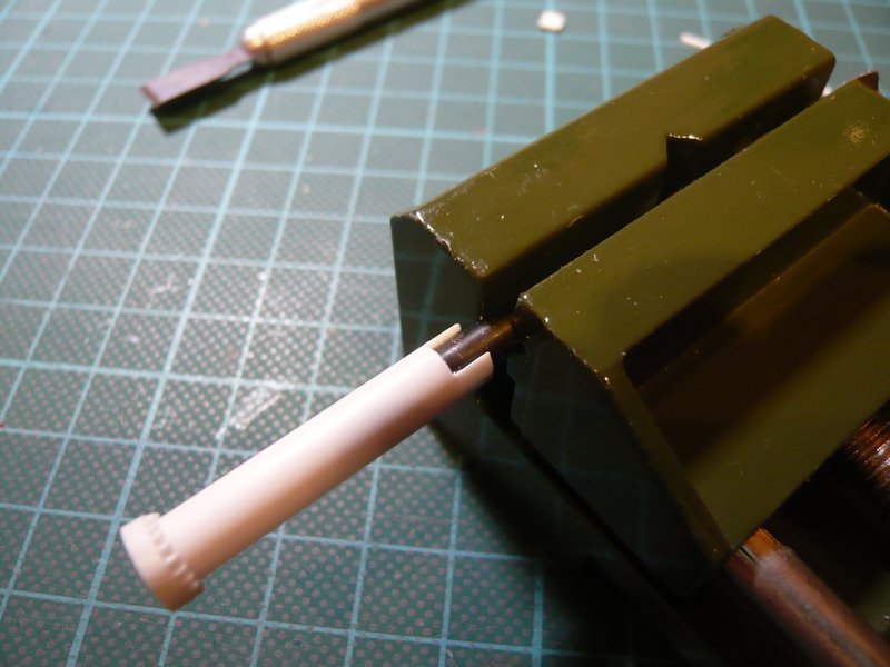
For that I have used this cutter blade with straight blade, which can be applied as a wood chisel. For that I have pushed the tube to a suitable drill shank and then carefully gouged out the opening, what has worked very well.

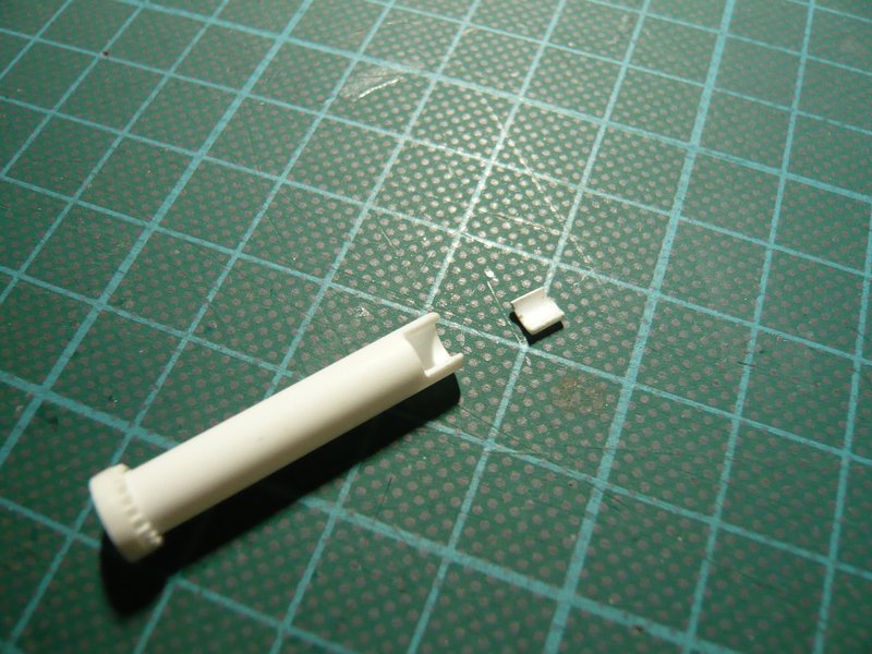
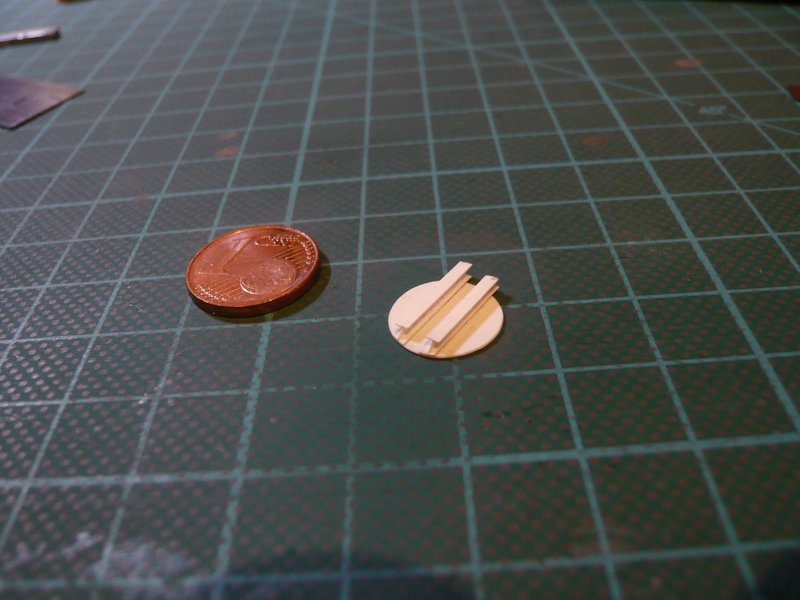
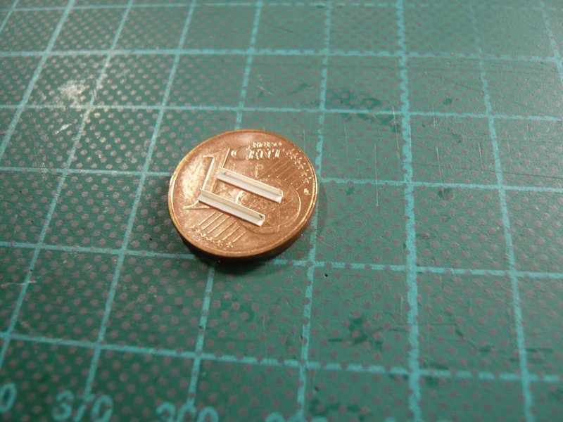
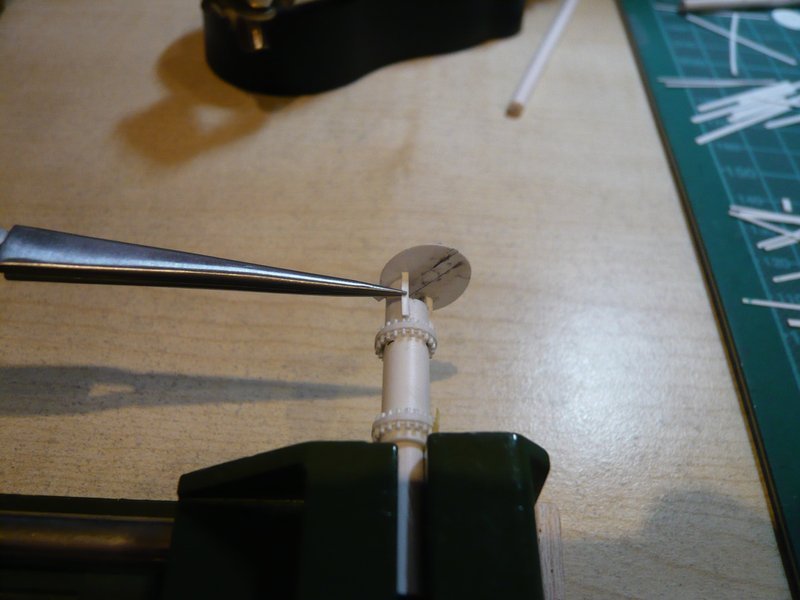
And as one can see, the edges are immediately much more accurate and cleaner than with the saw method and require almost no post-processing.

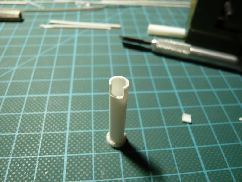
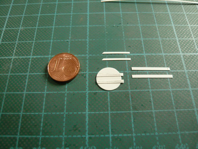
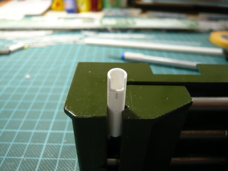
And the beveling can also be subsequently attached smoothly.

And that’s why I will now apply this simpler and more accurate method.

4 Likes

Good to see you back on the saddle and in action on this project. I was starting to miss seeing this.

I remember that rainbird you posted or worked on while back. I thought you were done with the top deck details but then again it is always nice to make new and improved details as you move forward even if it seems two steps back.

1 Like

Thanks Mike,

I hope I have found the right place to get in with my report to move forward.

2 Likes

Hi everybody,

after the pre-tests for cutting out the opening under the cover today follows the next step, and those are the flange rings with the screws.

Since the six Rainbirds have different forms, this should be shown in an overview.


Source: NASA

While Rainbirds B1, B2 and A1 are mounted directly on the MLP Deck, the other three B3, B4 and A-2 are standing in small recesses on the Blast Deck, as can be seen here.


Source: flickr.com (Andrew Scheer)

While all Rainbirds have two flange rings, screwed together with each other at the top, these three Birds in the Blast deck have only one flange ring at the bottom, which is directly screwed on the ground in the recesses. The three B1, B2 and A-1 standing on the MLP deck however, have two flange rings at the bottom.


Source: NASA
And so finally get to work.

First I have cut the pipe with the opening to the final length.

And now to the screws on the double flange rings of the two Rainbirds B-1 and B-2, with their screws (Ø 0,5 mm) I had recently begun already.

Here two strips 0,25 x 1,0 mm are placed on the bolt row, with which the “cartridge belts” are later glued around the tube. In order that this tricky structure can not stick at the cutting mat when glued with Methyl Ethyl Ketone (MEK), everything is precautionally put at a metal sheet. 
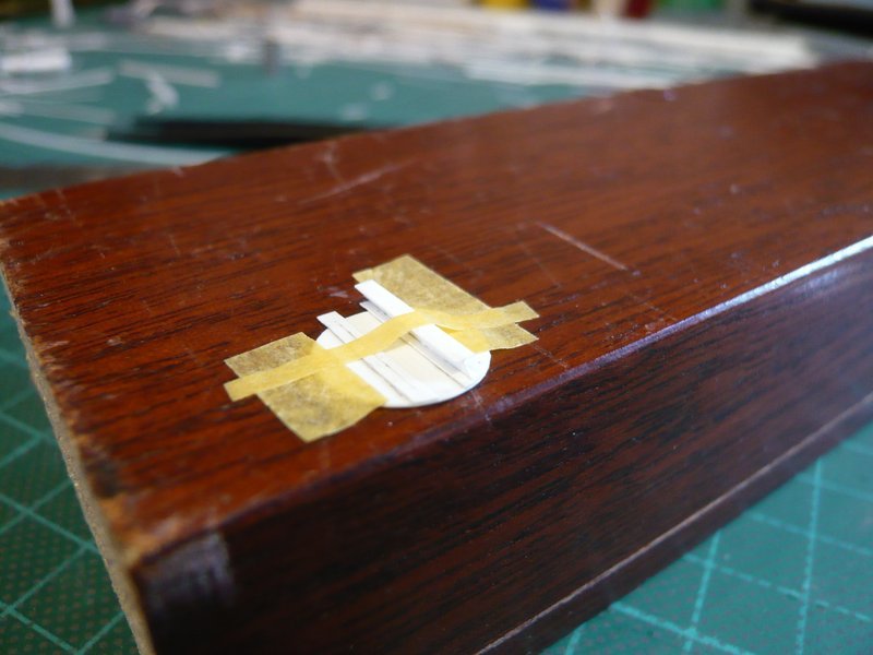
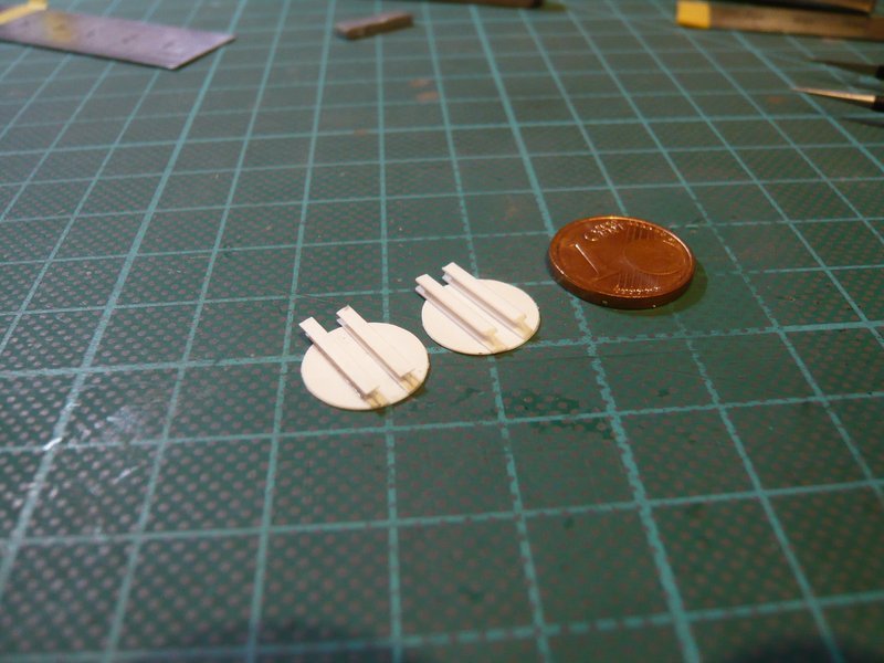
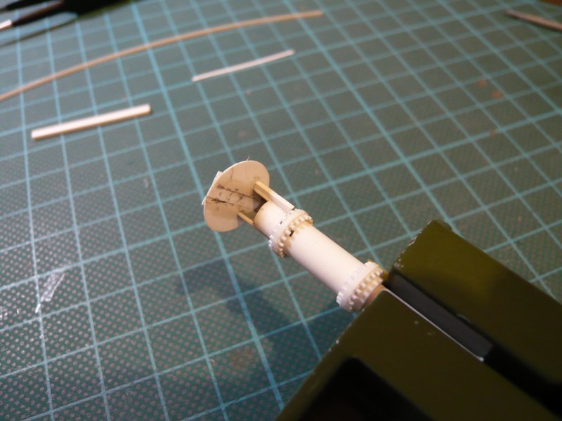
Then followed the gluing of the strips, firstly from the top,

and after removal of the templates even from below. And hard to believe, but even the structure has initially glued slightly on the metal sheet and had to be carefully detached with a chisel.

Then I have separated the bolt row in the middle between the strips,

and after that the screws have been reduced on both sides up to 1 mm.

To do this as evenly as possible, I have applied a 1 mm wide strip and separated the protruding ends with a chisel, which has so far completely worked well.

And those are the two 3 mm high cartridge belts, each seen from the inside.

To see how the whole thing now looks before gluing the belts around the tube, here they are placed on the tube above the sketch,

and here for more clarity without the sketch. And on closer inspection, I mean that the screws somehow seem to be a little bit too long, or what do you think?

And therefore I have placed my first cartridge belt pattern for comparison beside it, in which the protruding screw length is slightly less than 1 mm, what would please me better by its proportions.

But about it I will have to think once more …

4 Likes

As Mike said, it’s great to see this project get going again…

That is an ingenious way you thought of to make the flange and the screws/bolts. And as I look at them and size, I would say they are pretty much on the money. They look really good :+1:

1 Like

Thanks John,

this was truly one of my better ideas that I still like today, very complex but pretty clever.

2 Likes

Hey folks,

meantime I have the 2nd screw-belt also sanded down to 2,5 mm height.

The final belts should ultimately look like this, as I have tried it in this test with the narrower strips 0,25 mm x 0,75 mm,

everything back as before.

This time I shortened the overhangs to 0,75 mm and applied the same Evergreen Strip for cutting off.

Cropped from both sides that looks like this, where the screws now about 2,4 mm high and no longer needs to be reworked. And by shortening with the chisel this belt now looks much better than the top two sanded.

And now I have glued the lower belt, I have pinned him at the beginning with MEK and then gradually wanted to glue around the tube. But at the next adhesive point the strip is broken when I touched with the MEK paintbrush, and I had two parts. And immediately the memory came back when this mishap happened for the first time at the clamping rings of the Pipe Supports.

For this gluing really must be used CA because MEK it is deadly! So I glued the rest with CA, and then trial basis round the tube and has fit quite well.

Only cut the rest strip and glue the end.

That’s it so far and looks quite acceptable.

Now is still missing the outer strip, and then comes the upper screw-belt.

5 Likes

Hello everybody,

and here is the next update.

Today the lower screws-belt got its outer strips (0,1 mm x 0,8 mm), now only the spaces between the screws must be filled with wood glue.

And next the upper screws-belt is glued, but this time I have used CA. After gluing the starting point it went stepwise around.

And in the end everything went on well, as might be expected.

And here the bird is ready for the outer strips,

and now it’s done already.

Now I have the cover placed provisionally, and so the bird is now slowly fledged and and looks pretty cool already.

And here is finally a comparison of the birds, left the 1:144 and in the mid 1:160 bird of David Maier’s Paper Kit. And I mean that the new bird has become a very good compromise to my MLP and has a more realistic shape.

Tomorrow will follow the profiles beside and rear of the opening and on the cover, whereupon I’m curious already.


Source: NASA

Every day new nice details …

3 Likes

Hello there,

here are Evergreen’s standard profiles that one would need now, from left to right:
H-profile, angle profile and T-profile, each 1,5 mm x 1,5 mm and with web thickness of 0,3 mm and thus look relatively massive.

That becomes still more clearly on the cover (0,25 mm),

and looks at the Rainbird already nearly brutal.

So I will try to scratch these profiles by using 0,1 mm or 0,15 mm Styrene, with probably look better.

3 Likes

Hello friends,

that’s why I have tried it once with thinner Styrene (about 0,15 mm).

Since the production of the vertical angle and T-profiles should be a bit easier, I started with the trickier H-profiles on the cover and cut first 1 mm and 1.5 mm wide strips. This looks easier than it is when the strips should get the same width.

The gluing of the web (1 mm) on the lower strips (1,5 mm) is a bit laborious because one must fix it centrally as well as vertically, wherefore I have used small magnets. Only then one can glue by cautiously brushing both sides with MEK.

Much more difficult, however, is the gluing of the top stripe, because one must reach into the 1 mm gap with the fine brush with MEK. But that’s me yet succeeded, as one can see.

And here one can see the comparison of the two variants, left the previous Evergreen H-beam and on the right the scratch version that looks a bit finer,

although the contours in the white-on-white shots come out not so good.

And although this procedure was pretty tricky, I might also try another variant with 0,1 mm Styrene, what should be in fact the correct scale.

Here on the fast one a short update with the comparison of the two T-beams for the back side, which have the same width (1,5 mm) as the H-profiles, left a standard T-beam, and right the scratch variant by using 0,1 mm Styrene.

And the thinner angle beam should be similar uncomplicated. Only the H-beam is a bit trickier, which is why I still have to puzzle out a somewhat simpler assembly technique.

We will see …

5 Likes

All I can say is who needs 3D printing when you have hands that can create this kind of detail. :wink:

1 Like

Thanks Mike for your great compliment,

a true word at the right time.

1 Like

Hello everyone,

today I have now tried to put theory into practice and to bring the thinner H profiles on the hood.

And accordingly to the US standards I have adapted the dimensions of the H profiles to those of W10 beams and have cut for the webs (5’‘) Styrene strips of 0,1 mm x 1,0 mm and for the upper and lower flanges (0,9’') 0,15 x 1,5 mm.

As spacers for the bottom two strips I have placed an Evergreen H profile with 2 mm width on the cover, and alongside glued the strips (each with something overhang) right and left with MEK, first outside, and after removal of the spacer inside,

After trimming of the overhangs now followed the assembly of the profiles from the prepared strips.

As written previously, I first glued the slanted webs on the upper flanges, which were fixed between two steel rulers and then painted from both sides with MEK.

The line-shaped adhesive sites at the 0,1 mm webs are inevitably minimal and have only a limited stability, which is to be considered during the further assembly.

And now comes the most difficult part of the assembly, this T profile must be placed centrally as well as vertically above the lower strips, and then glued, wherefore this I have used this jig.

The left stopper is a cutter blade, and beside the T beam, which was carefully fixed with tape under the front edge of the ruler.

In this position, I could now glue the front part with MEK, and then after alignment the rear part.

But because the attachment to the tape strips was quite stressful, I wanted to try to simplify this action with a kind of double-sided adhesive tape strip, at which I have attached the profile.

The alignment of the ruler at the stopper and the gluing of the web went well so far, but then came the flop, because the upper strip began to peel away when the ruler was lifted.

That’s why I have quitted this method and fixed the profile only with tape strips and glued the web in this position,

what also has worked.

And in a similar way, I then glued also the other profile.

And here for comparison right the cover with the two Evergreen H profiles (1,5 x 1,5 mm) and to the left the Scratch variant that looks still finer in reality than it comes out here in the image.

And also by the somewhat lower height (1,3 mm) of the new W profiles the Rainbird with this modified hood looks a bit nicer, I imagine at least.

And tomorrow then will follow the rear T profiles and the lateral angle profiles.

4 Likes

Every time its a mind blowing show of detailing, and some of it is so small, yet everything seems to be mirrored perfectly. This really is technical brilliance

1 Like

Thanks John, your compliments are overwhelming.

Stay tuned, the show will go on.

Hello everybody,

today now to the profiles under the hood, which one due to their “size” barely can handle, which is why this already needs the most pointed tweezers and again a lot of patience.

Here, first the production the angular profiles 1 x 1 mm, for this I have glued a strip 0,15 x 0,9 mm to a strip 0,1 x 1,0 mm, because of the small dimensions all again with MEK.

And no matter how you do it, with or without spacers,

one definitely needs a stable support or stopper.

First I have made double the length of two angles, but this is not necessarily recommendable, because the angle section should still be cut to the final length, but this is not so readily when the laboriously glued angle should remain intact.

So one must cut both sides separately with the chisel, because the delicate angle could break due to the minimal adhesive point otherwise,

but this can be avoided.

Here again the comparison of different angle profiles. The two lower angles are scratched, above it a brass profile 1 x 1 mm, wherein the thickness is 0,35 mm, and above it the smallest, also 0,35 mm thick Evergreen Profile 1,5 x 1,5 mm.

And now to the gluing of the two mini-angles under the hood, which was relatively tricky because of the necessary accurate and secure positioning, because I again wanted to glue with MEK of the small web widths. For this the parts must somehow be fixed, which is rather complicated.

First of all the Rainbird needs a secure hold on a rod. Thereafter, the length of the angle had to be adapted to the space between the hood and screw circle.

Here you can see the mounting device with the angle in the cross tweezers, and for aligning and gluing I had to put on my headset magnifier.

That was all in all again a tricky business, but it has finally worked,

and with the result, I can be more than satisfied, I think.

Now only missing the two rear T profiles, but they can probably attached something easier, because space is more accessible than under the hood. But without tweezers, etc., it also will not work …

See you later guys and thanks for watching.

3 Likes