Space Shuttle Launch Complex 39A with Challenger STS-6 (1:144)

Hello everybody,

and with the cover strips it went on.

They are as well as the strips for angle profiles and T beams all hand cut, unfortunately not by Evergreen.

And this is the fifth and last cover strip, here on B-4.

And so now to the profiles, and there was as next the Rainbird B-2, whose profiles correspond to those of B-1, which also reach to the upper screws belt.


Source: NASA

Here the B-2 is already completed, with angular and T profiles.

The same arrangement of the profiles is used on B-3, which is standing on the Blast Deck, here first the angular profiles.

And now follows the B-4, whose profiles are shorter on all three MLPs than that of the other birds, for whatever reason, as you can see here in the photo with Andrew Scheer.


Source: flickr.com (Andrew Scheer)

What must be, must be.

And here are the two Rainbirds B3 (right) and [B-4/color (left), in which only missing the rear T beams,

which tomorrow form the crowning conclusion of this chapter.

5 Likes

Hello everyboy,

welcome for the Rainbird’s Final Countdown.

Now follow the missing T beams of the last two Birds B-3 and B-4.

Next in line was the B-3, for which the webs were glued in a proven way first,

and then on it the flanges.

Then the same procedure on bird B4, as usual.

That with the shorter profiles of this bird I had already explained.

Now only the protruding H beams have to be straightened.

And so the nice flock of birds is now finally complete.

And barely fledged, the birds want to swarm out already.

And in celebration of this milestone, I have now got the MLP out of the cupboard to see how the Rainbirds would fit. And I’m very satisfied and mean that they fit quite well.

Only the recesses in the Blast Deck have to be adapted, since they are a bit too small, especially for the A-2. And with paint finish all things will surely yet look a bit better.

That’s it for today, and this Milestone of course calls for a celebration!

In this sense, Cheers!

6 Likes

Hello everybody,

since I will be leaving for Washington D.C. the day after tomorrow for the first stop on my this year’s USA trip, it’s time to pack my bags, which is why I urgently need to make a break here, and will report back to you when I’ll be back home on November 2nd.

Have a good time and stay healthy my friends.

3 Likes

Safe travels.

Thanks Ryan,

I think this trip will even top my last year’s trip, the agenda is jam-packed!

1 Like

Looking awesome Manfred. Hope you Trip goes wonderful. Post some photos from it when possible. Have fun!!

Great update to leave on, and enjoy the holiday Stateside …

1 Like

Sadly I was on point at her last flight. Because of the Teachers in Space program. Before doing anything May I suggest you read a book Called.“Challenger”, I forgot the Authors name, but it points to some very unnerving facts!( Got it from the Library).

Thanks my friends for all your good wishes.

1 Like

Hello everybody,

after yesterday’s election day in USA, I want to get back in touch with you, my friends.

I’ve had five weeks with great experiences in which I’ve seen a lot and met many new friends.

Unfortunately I also had to say Goodbye to two of my friends forever.

John O’Connor †

John is buried in Titusville, and I paid my last respects to him at his grave.

His name is not yet engraved on the urn gravestone, but I’m in touch with one of his colleagues, Jim Siegel, who will take care of all further matters in his spirit.

His unique Shuttle Panoramic images on his website will remain in our memories forever.

Judy Gale Roberts †

After I learned of her death from her husband Stephen, I’ve contacted him and arranged to meet him in their studio in Seymour, Tennessee, in the mountains, where he was showing me all of her awesome artworks,

as well as photos from their life from the good old days.

Strange but somehow familiar, I had the feeling the whole time that Judy was still omnipresent in her studio.

As remembrance Stephen gave me this wonderful Intarsia duck, which I was very happy about and which will get a place of honor in my studio.

May John and Judy rest in peace, forever remembered …

3 Likes

Hello everybody,

these were dramatic and sad fates that overshadowed my USA trip this year and accompanied me constantly.

Nevertheless, I have to carry on and I’m trying to get back into my two project reports STS-6 and Psyche Space craft and summarize my travel experiences in a suitable form, which is not easy for me.

So first of all I have placed the memories and framed the posters and autographed photos from the encounters with the three astronauts in the Astronaut Encounter and have built a bridge for myself with the picture wall this way.

In this sense, here is a little flashback to my Return to KSC Tour 2024 this year and the interesting encounters with members of former Shuttle crews in the Astronaut Encounter.

Charles D. Walker - STS-41D, 51D, 61B

KSC VC: 10/23/24 - 10/26/24

Mike A. Baker - STS-43, 52, 68, 81

KSC VC: 10/27/24 - 10/31/24

Anna L. Fisher - STS-51A

KSC VC: 11/01/24 - 11/04/2024

And during each encounter, there was a big surprise when you saw the astronauts live on stage compared with the photos from their missions that time.

So much for a first little flashback to my Return to KSC Tour 2024 this year.

4 Likes

Good to get the update :+1:

1 Like

Thanks John and Hello everybody,

and after a longer break let me come back to the SSWS pipes that I had involuntarily to leave so about a year ago because of the emergency surgeries to the Exhaust chambers (SRB/SSME).

And already again I realized how fast one is out of business and must try to understand all the pipe details again.

Therefore, here as a reminder again the known drawing with the respective pipe diameters.


Source: NASA

And so therefore, a new start for the big 24’’ main pipe (Ø 4 mm). The 36 supports for this line I had already completed at that time.

Since within the MLP Report now also some NASA drawings are available, I have used this one as a template for a bending jig.

However, this drawing had at first to be adapted from the initially geometry of the SRB Holes (1:160) to their widened shape (1:144).

Then I have transferred and cut out the inner contour of the ring line onto an Balsa board (8 mm).

And around this template the rod (Ø 4 mm) is then bent under a hot air stream.

And this I’ll try next time.

6 Likes

Manfred, glad to hear that you were able to meet these real life hero’s. Looks like the wall of honor continues to grow in your man cave!!

1 Like

Yep Mike,

it will be continued step by step, as you can see here.

Charlie Walker and Anna Fisher and me, beneath an awesome 3D Shuttle Lift-off photo.

And in memory of Judy Gale Roberts, the nation’s most widely known and revered Intarsia artist, her impressive Intarsia Duck, which her husband Stephen gave me during my visit in Seymour, is hanging now in my studio,

next to her picture during the unveiling of her one-of-a-kind Apollo 11 50th Anniversary Intarsia in their studio in Seymour in 2019.

Forever remembered … It’s hard for me to let go.

3 Likes

Hello everybody,

before the “sharp” bending of the 24’’ ring line (Ø 4 mm) around my new Balsa Template I first made a few drag tests under hot air stream in order to get a feel for.

And as one can see, this is quite feasible, the only problem is to produce the desired diameter of the taper at the right place. The taper in the left image is from Ø 4 mm to Ø 2,3 mm. With simultaneous defined bend it is then more difficult to produce reproducible dimensions and arches.

Therefore the use of the two-component modeling compound Apoxie Sculpt appears to be almost more promising, especially for the outgoing pipes and transitions. And I wanted to try out this alleged super weapon already longer.

Here we go. These are the two components A (right) and B (left), which must be thoroughly mixed together in the ratio 1:1, so that the mass is well hardened after 24 hours.

Both components are doughy, so that one can form two such marbles according to need,

and kneads them with each other intense such a long time,

until one gets a uniform mixed color. Only now one can process the mass within about two hours, therefore do not panic!

Now the mass is spread almost like dough and can then be modeled to one’s heart’s content, either flatten with fingers or even work on with special spatulas, whereby occasional moistening is advisable and useful.

Excess material can be removed or missing material be adapted, nothing is impossible within two hours.

Since the remaining material is unfortunately waste, one should assess its needs as well as possible in advance what is not yet succeeded to me, as you can see.

And then one should leave things alone to dry for 24 hours before one is possibly thinking about reworking by grinding, should this be necessary.

And I’ll be watching next time closer.

4 Likes

Hello everybody,

and therefore now to my first impressions of Apoxie Sculpt.

This modeling compound is really easy to work with. Once hardened, it is light gray and stone-hard, absolutely tight and free of cracks.

So I have only yet smoothed something the transitions with a sanding sponge 2000s, that’s also already.

It focuses first on this thickening (36’’ ≙ Ø 6 mm) in the ring line, in which the 36’’ inlet pipe discharges, which is coming out of the chamber’s corner.


Source: NASA

The shape of the center part is not yet final, because this area is still too long and a little too thin. This part is instead 12 mm only 9 mm long and the diameter 6 mm instead the previous 5,5 mm, but this is finally taken into account in the pipe.

And similarly, it looks at the other side of the line,

where the ring line behind the LOX-TSM tapers from Ø 4 mm to Ø 2,5 mm.


Source: NASA

With this result, I am quite satisfied for the moment, so I will most likely remain in this variant. I.e. I’ll bend the arched outlets into the shafts via respective balsa stencils and then attach, and then model the transitions with Apoxie Sculpt.

I suppose that this way the dimensions and geometries of the outlet transitions will be reproduced better and more exactly than with the dragging technique.

3 Likes

Hi folks,

today only a few small detail corrections.

After careful watching of the T-shaped branch of the 36’’ feed line in the shaft corner I noticed that the transitions from the thickening to the 24’’ ring line looks slightly different than that of my prototype.

As you can see in the photo already shown several times, the transitions run slightly obliquely and concavely,


Source: NASA

what I had not initially considered. With me they were even more arched slightly convex. This is not so serious, but the form is not yet correct.

Therefore, I have modified the left side accordingly, and it all looks the same better, I think, because the difference is obvious.

The post-processing went smoothly because the Apoxie Sculpt is so fine-grained and dense that there are no outbreaks.

And then still the to another problem, to which I would like to hint now in view of the occasion.

This drawing here with the dimensions of SSWS pipes has been indeed shown on several occasions, but a crucial thing always had been neglected.

This is the arrangement of the SSWS pipes on the MLP-1 which distinguish oneself from the other two MLP-2 and MLP-3.


Source: NASA

And these are the marked arcuate transitions between the SRB-supports and these bows in front of the two TSM’s, which does not exist on MLP-2 and MLP-3 in this form.

As one can see in the photo of MLP-1, in particular the rear bows and the corresponding supports are significantly higher,


Source: capcomespace.net

while in MLP-2 and MLP-3 all the bows have nearly the same shape and height, although the outlets are different, which I will discuss later.


Source: NASA

But I want to point out to the inner outlet once more, which looks at MLP-2 and MLP-3 like this and has other dimensions than I had recently given.


Source: NASA

There the end of the 24’’ ring line directly tapers into a 12’’ pipe, which then leads without further taper into the shaft, what I had not observed previously, especially because the opposing outlet has a taper after the bow.

Incidentally, this is clearly evident already from the drawing.


Source: NASA

But now it’s enough with detailed quibbles.

3 Likes

Hello everybody,

today it goes round, borrowing from an Oldie of The Spencer Davis Group - Keep On “Bending”, so everything has been said.

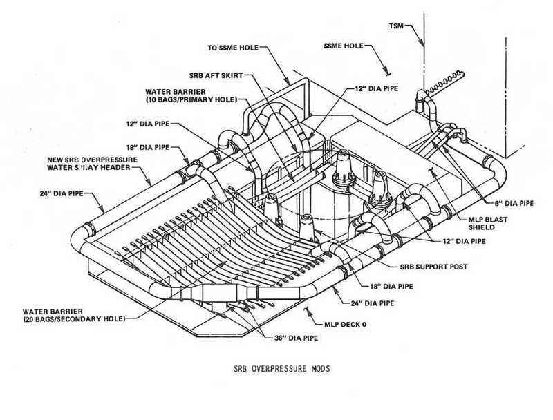
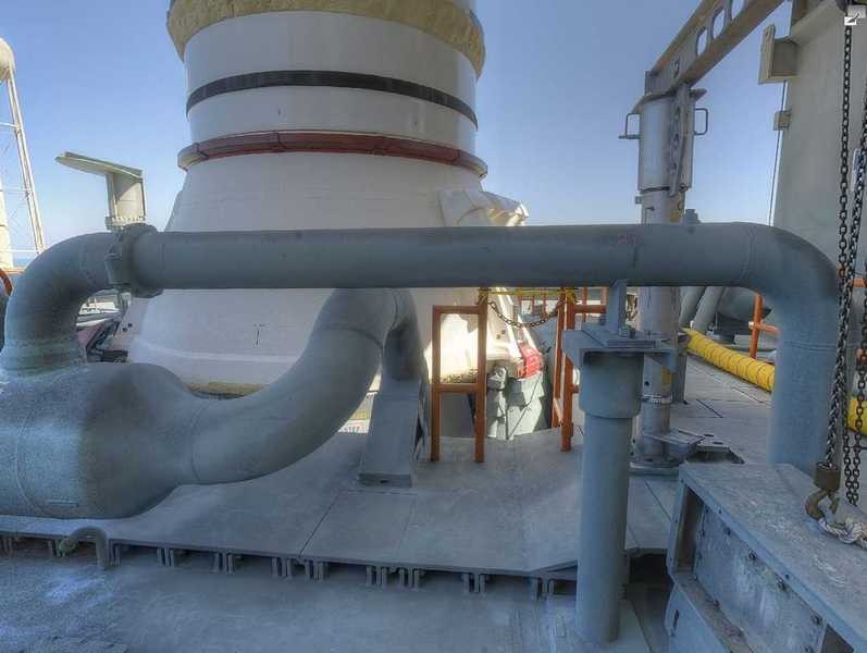
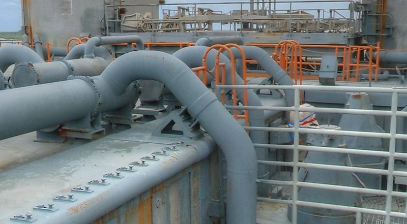
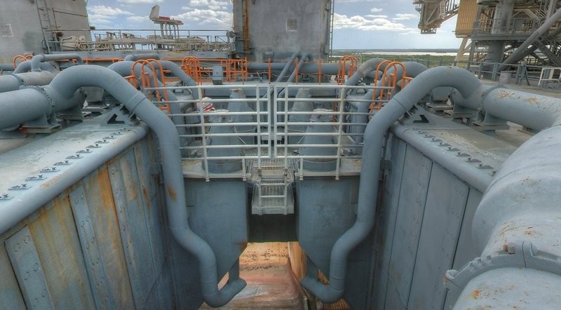
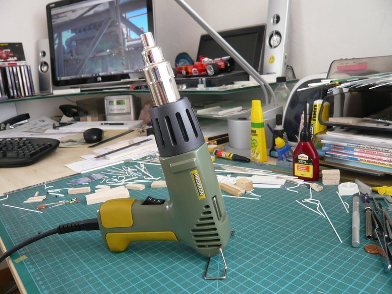
The thick 24’’ ring line is on the program, and therefore quick to the work. The hot air gun is already ready for battle.

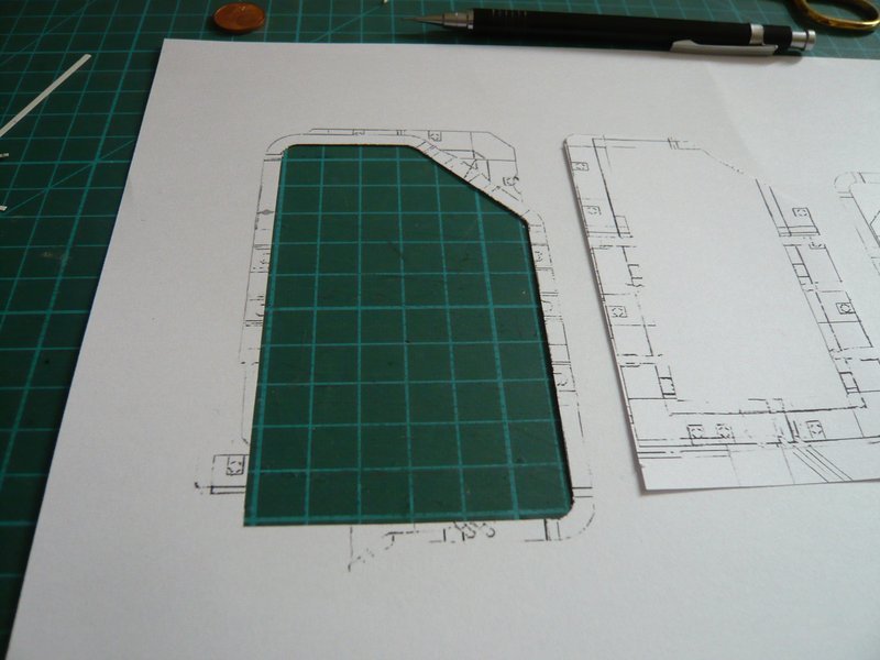
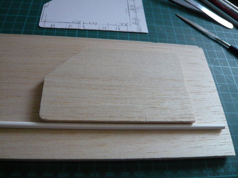
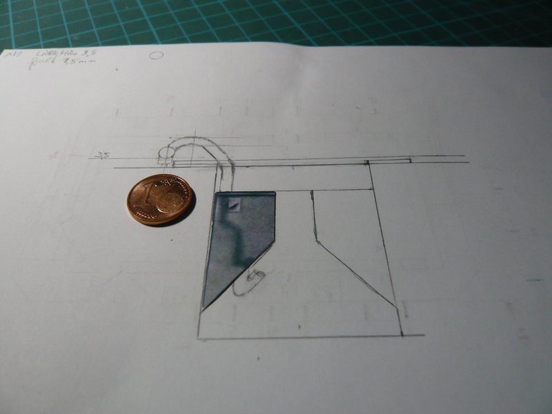
Before starting I still had cut a recess in the template, because the sleeve for the thickening of the pipe must be threaded before bending, otherwise one has a problem, because afterwards it’s impossible.

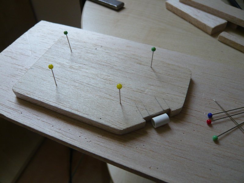
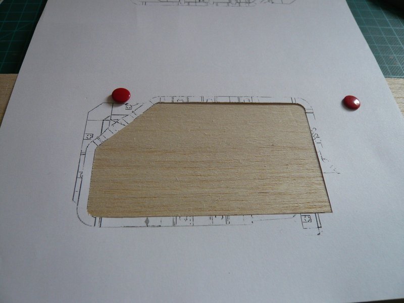
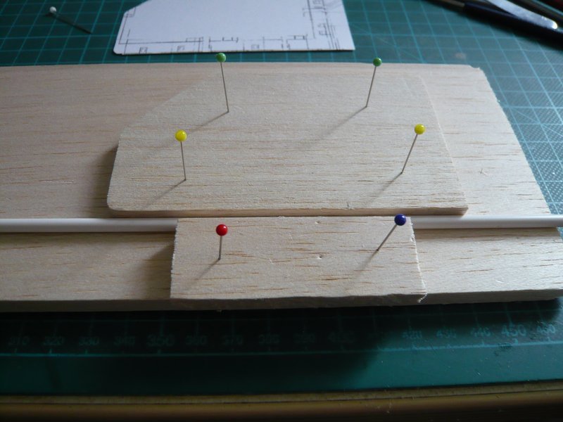
It’s important for the bending of the pipe around the Balsa template, that one gives the rod no chance to dodge, it must “obey blindly.” For this one must squeeze it into a stable Balsa corset til immediately prior to the bending point.

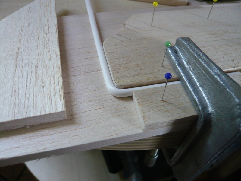
Then, the bending area is moderately blown with hot air while the rod is simultaneously bent gently until the plastic starts to soften what happens relatively abruptly. Therefore one should then align the rod preferably immediately and over the entire length at the next edge and fix it in this position until to cooling down.

And here the handy rod (Ø 4 mm) has got already its first 90° bend.

And if everything has worked well, this bending is virtually “frozen” and also after removal of the corset dimensionally stable.

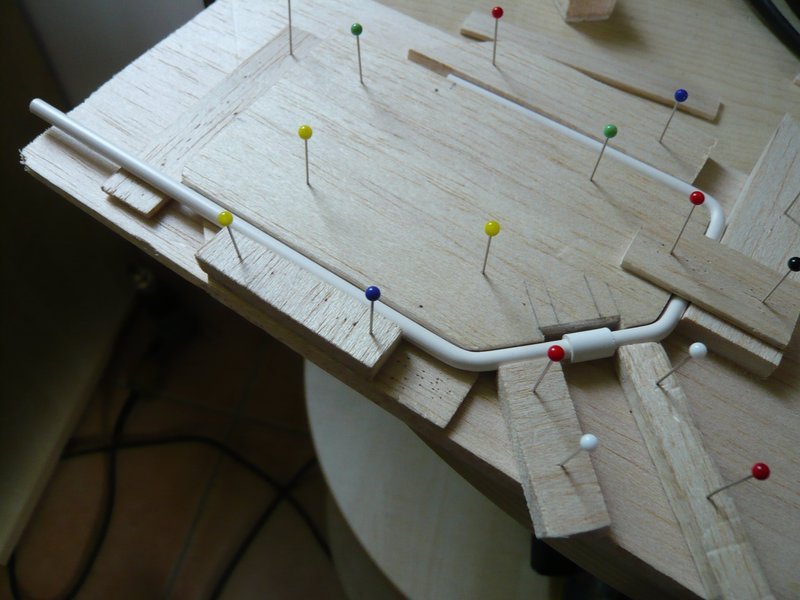
In order for the ring line remains planar during the following bends, because of the sleeve one must not forget previously to underlay corresponding compensating strips.

And then already follows the 45° bending along the slant with the sleeve in the recess.

Then the area for the next bending point is fixed again,

after which the second 45° bending follows.

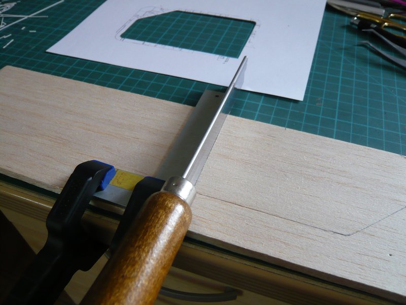
Since the next narrow retaining strip has offered too little support for the last bending,

a stronger Balsa board had to be used.

But with it then also the last bending has worked well,

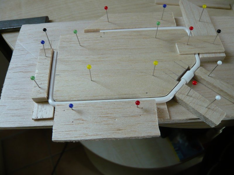
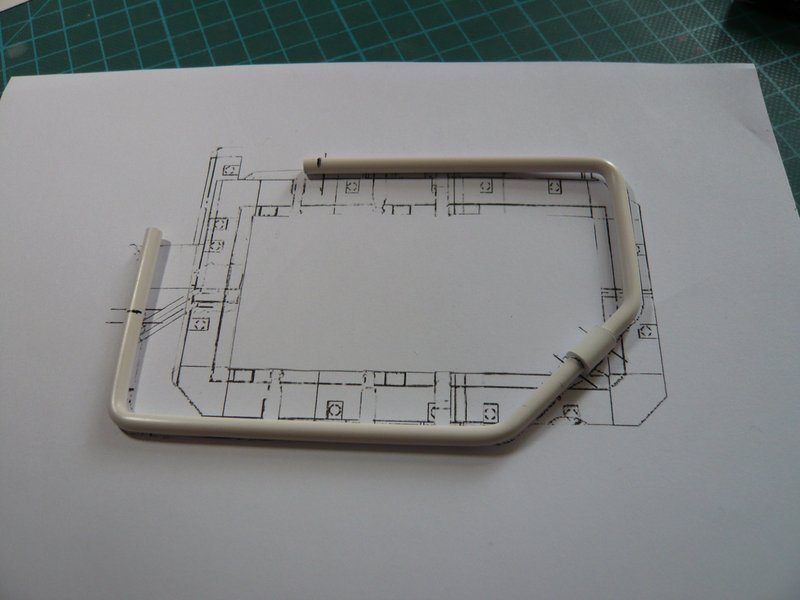
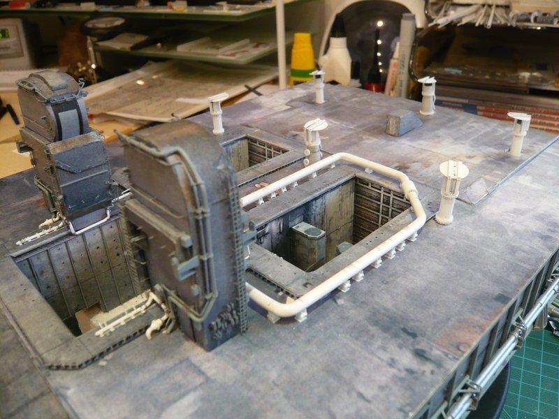
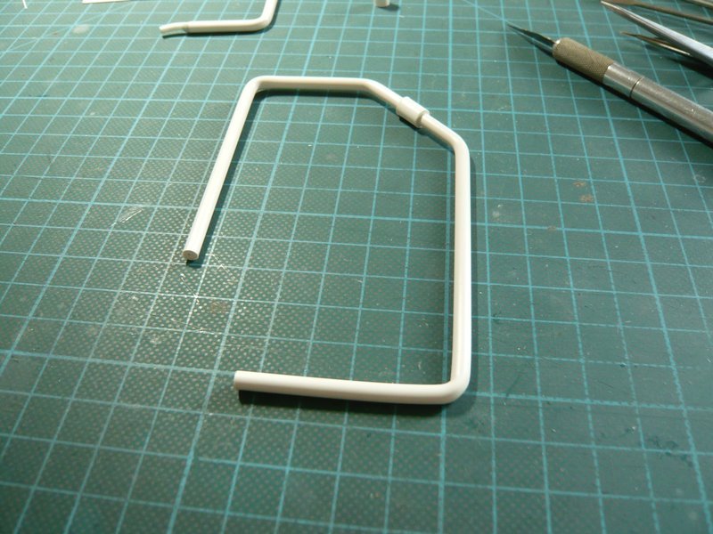
so that the ring line has remained dimensionally stable even after removal of the outer corset rods, what eventually was meaning and purpose of the whole exercise.

Okay, if you look closely, you can see that the last area still has a minimum curvature, which can still be smoothed.

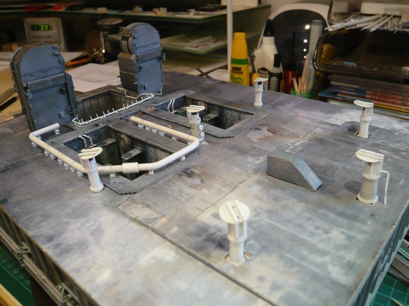
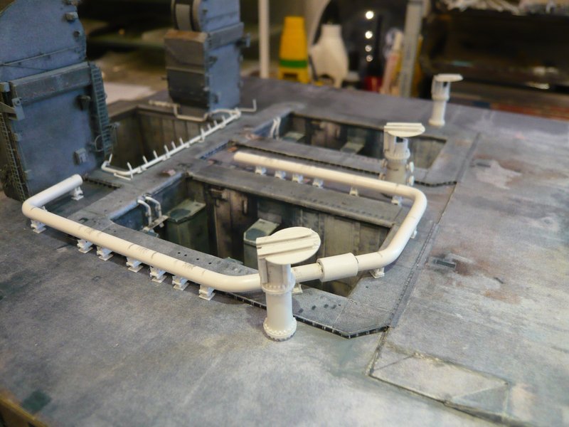
And because everything works the way how I had imagined, I can also quietly bend the second ring line.
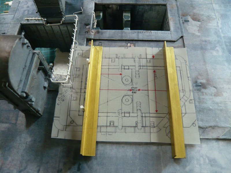
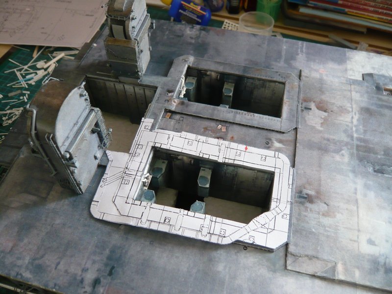
5 Likes

Hello everybody,

before the bending of the second ring line I still wanted to check their position on the MLP, here initially on the sketch, to which it fits very well.

And here the positions of all 20 Pipe Supports are now marked,

whereby the 18 supports for 24’’ Ring line (Ø 4 mm) are already finished and waiting for the test, of which there are both some with clamping rings (green) as also without (red).

Support No. 1 (red) supports the 16’’ rejuvenation (Ø 2,5 mm) immediately in front of the LH2-TSM and is constructed a bit easier.


Source: NASA

And No. 6 (red) is this longer support below the 9’’ Pipe (Ø 1,4 mm) which is running into the SSME chamber.


Source: NASA

Here I have the ring line tentatively set on the 18 supports, whereby Nos. 1 and 6 (red) are missing.

But that is not enough, because for the holders of the arcuate outlets of both ring lines into the SRB-shafts are needed in each case 12 of these supports (in the sketch blue) which are standing on the Blast Shields.


Source: NASA

They have a slightly different substructure, but in any case I need 24 of these tiny sickle-shaped supports, I’m looking forward already.

And here I also have arranged the six pretty Rainbirds to complete the picture.

And so now follow the four rear 18’’ outlets (Ø 3 mm), for which I have drawn this sketch.

These are admittedly not tapered, but five-fold bent, and are ending below the SRB Supports.


Source: NASA

And because I need four of these tortuous “earthworms”, a balsa template will be worthwhile again.

4 Likes