Space Shuttle Launch Complex 39A with Challenger STS-6 (1:144)

Hello everybody,

let’s get started with the first act of the new bending orgy.

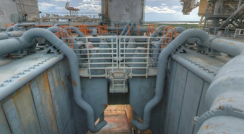
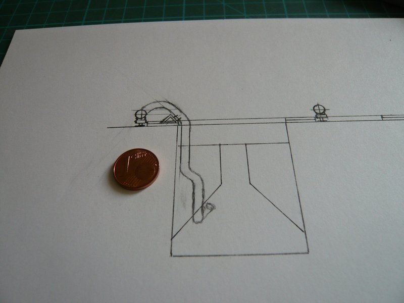
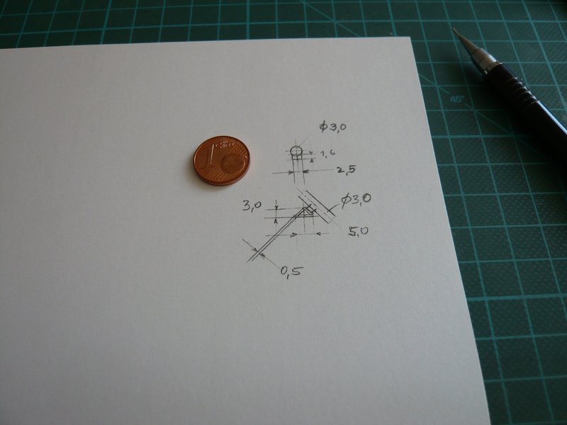
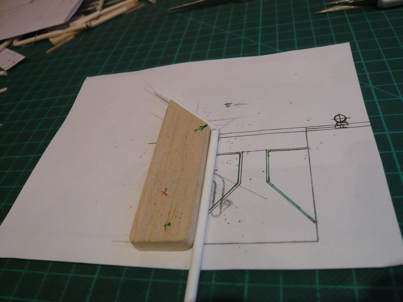
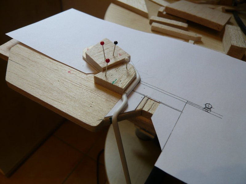
Here once again the sketch of the 18’’ outlet as a basis for the template, in which I have drawn already the pipe support on the SRB-Blast Shield, to this but later.

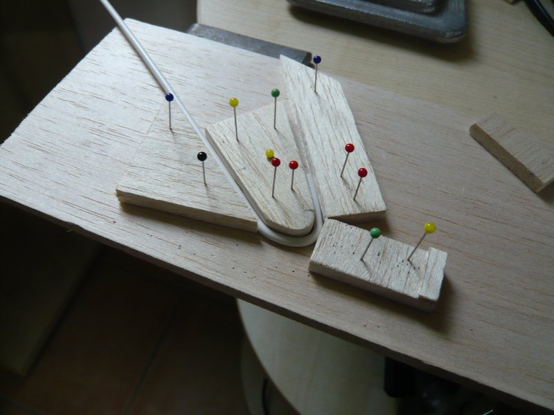
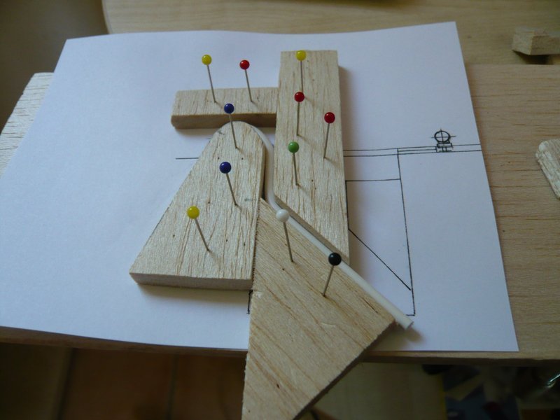
This time, the bending process is not as easy as with the ring line, in which it only once went all-around.
Therefore, this template (left in the image) can be used only for the upper rounding and the subsequent outlet, whereby a consistent holding is very important.

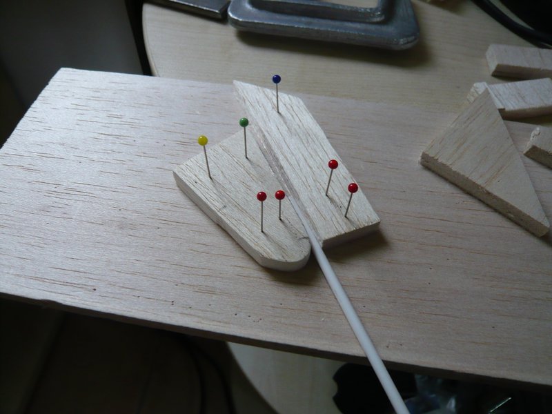
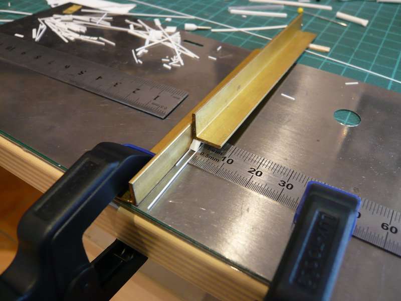
And during the stepwise bending then the hot air gun takes action.

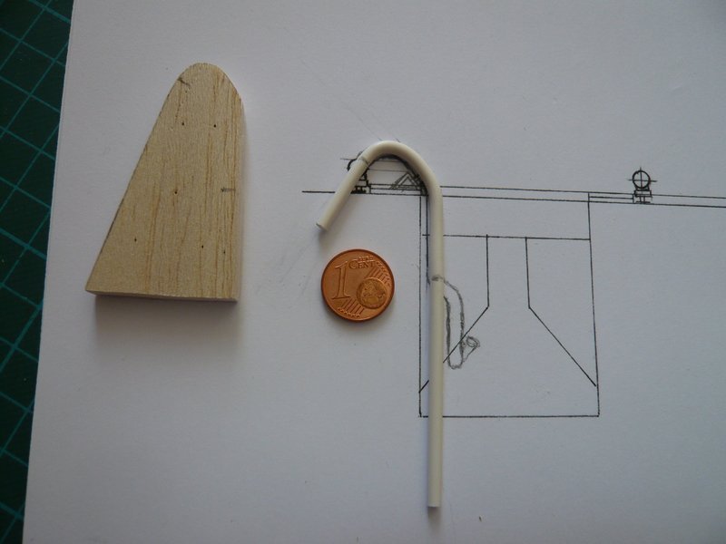
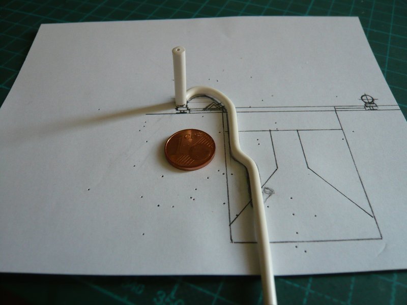
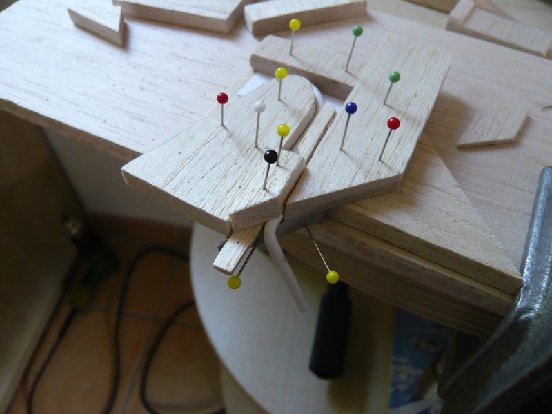
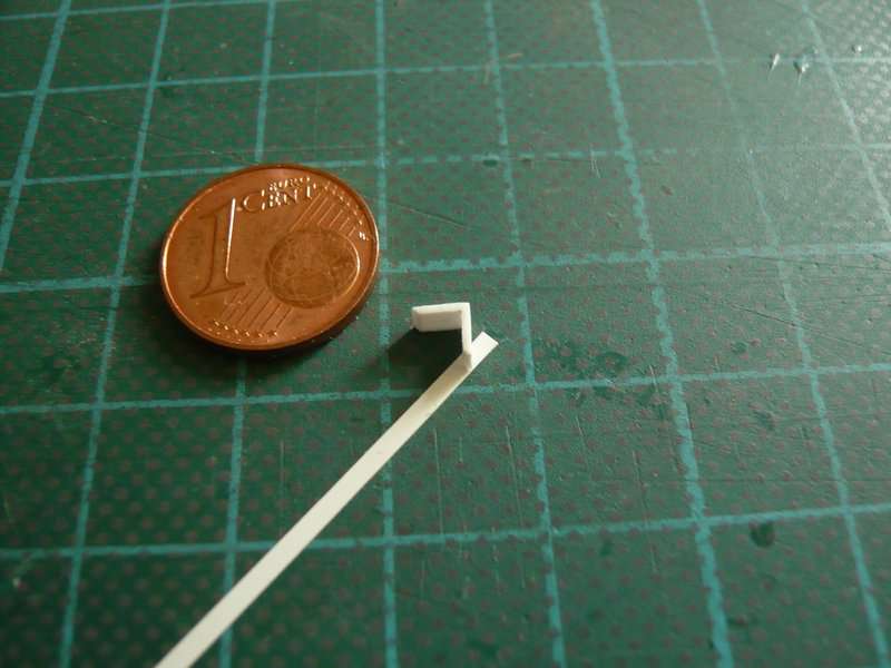
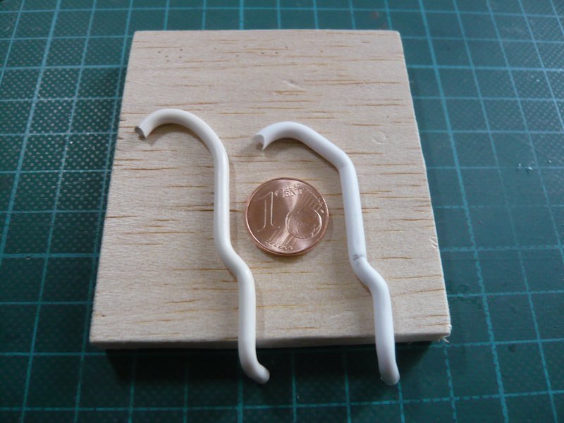
This is the intermediate result, which seems to be quite useful, only the short piece after the upper arch should actually be still a bit flatter, but it could not be aligned close enough. But it became probably something too hot for my fingers.

Now the overhang part can be separated and then the junction be rounded.

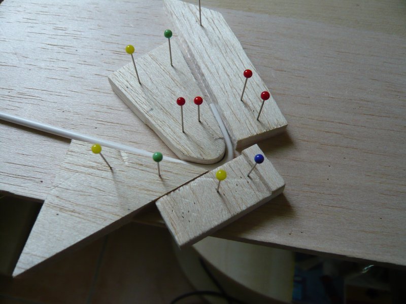
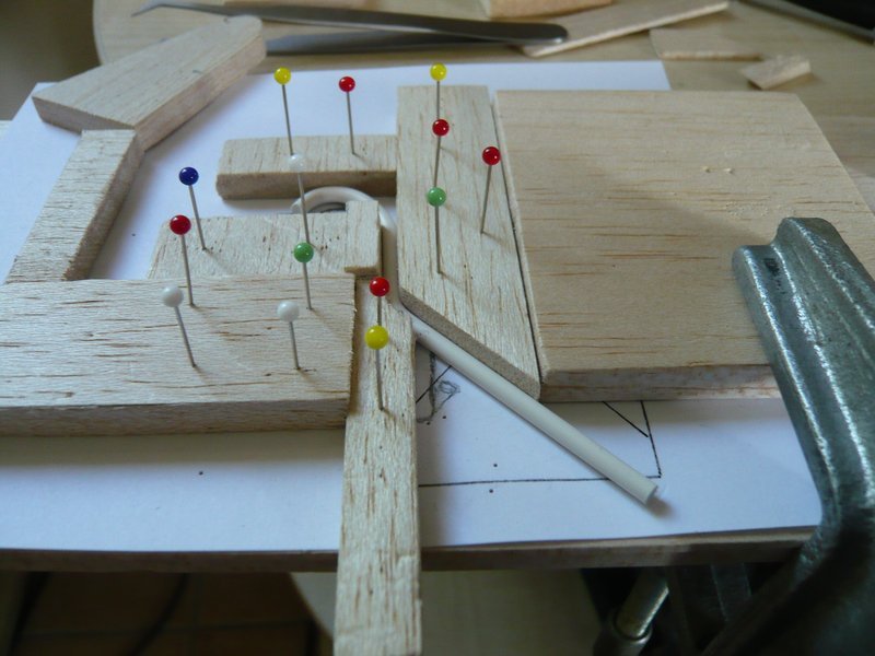
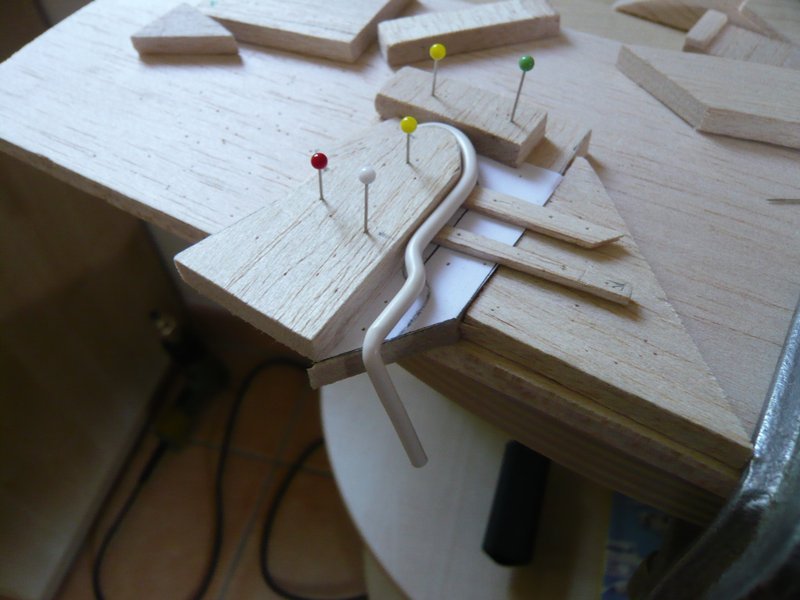
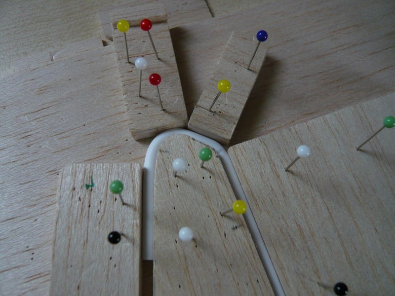
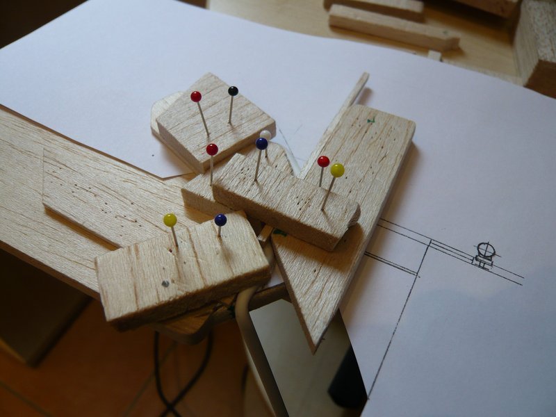
In order to bend the following short slant it must be re-clamped.

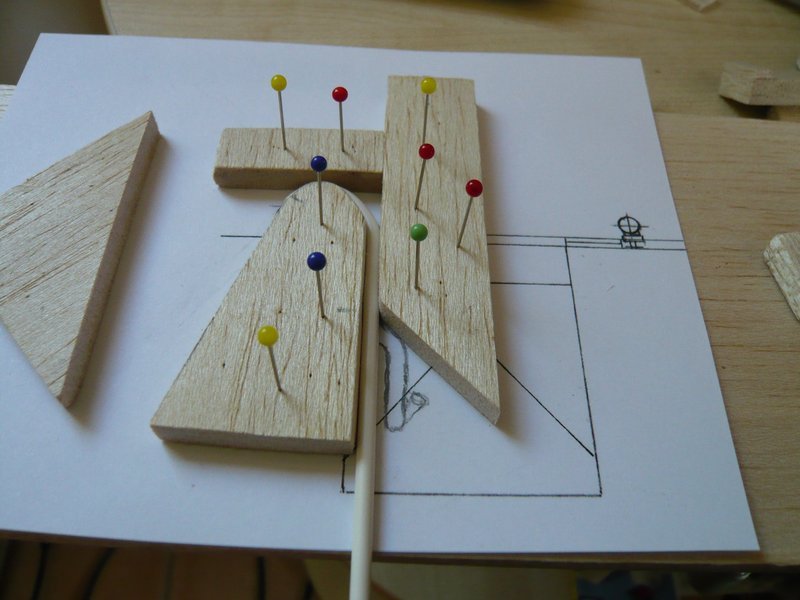
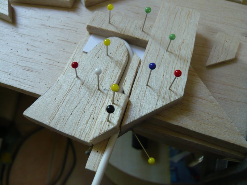
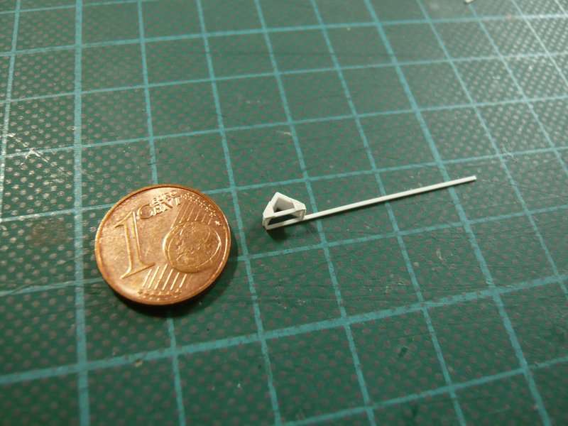
For this the rod must be aligned with the balsa triangle narrow to the slant. After fixation of the triangle with the pins it must be blow-dried again, and only after cooling, the clamps can be removed.

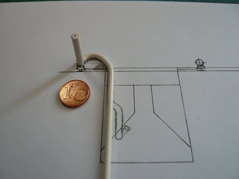
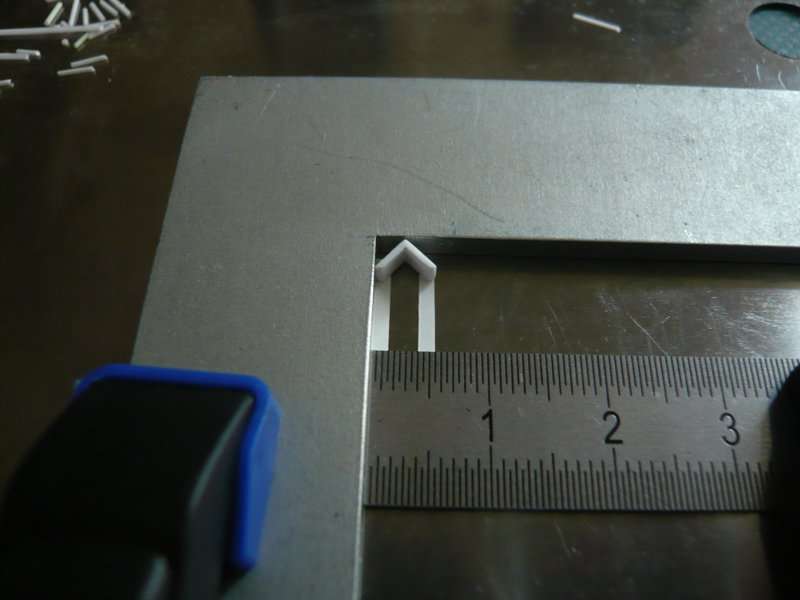
Thereafter, the rod should should fit snugly and not splay back again. And then follows the second bending downwards,

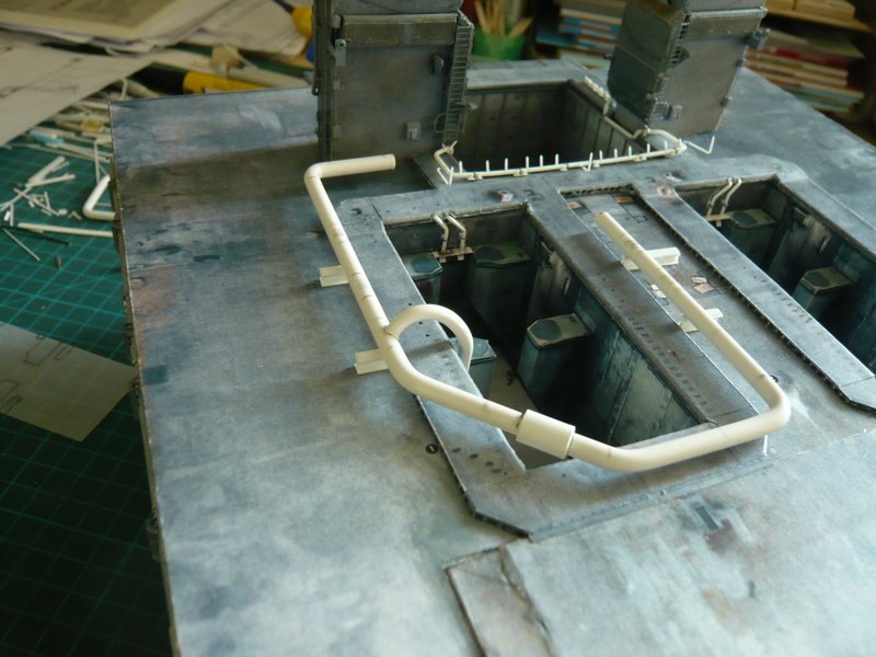
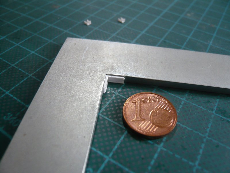
whereto I yet again have re-clamped and used a more stable board with slanted corner.

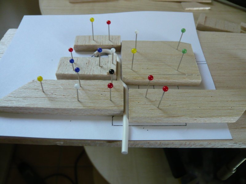
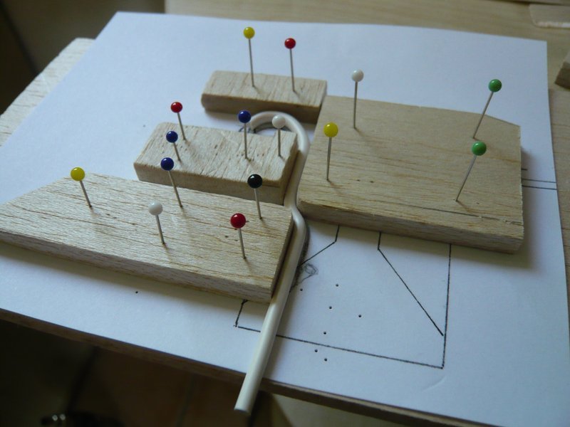
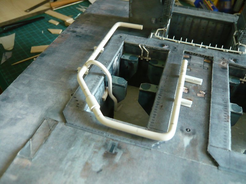
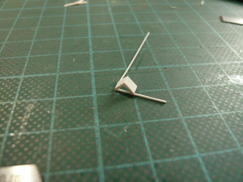
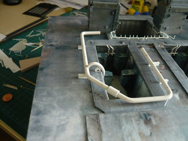
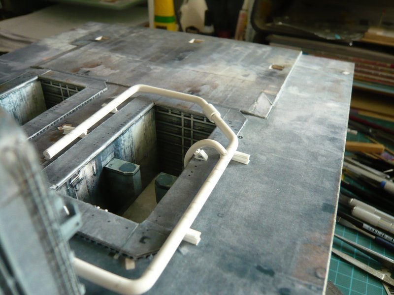
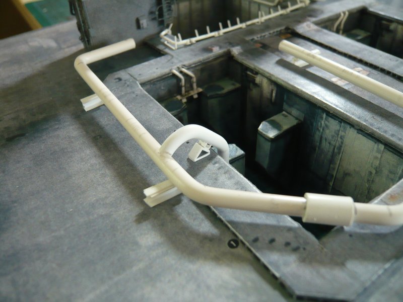
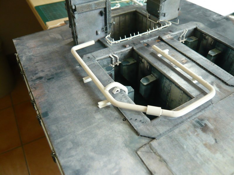
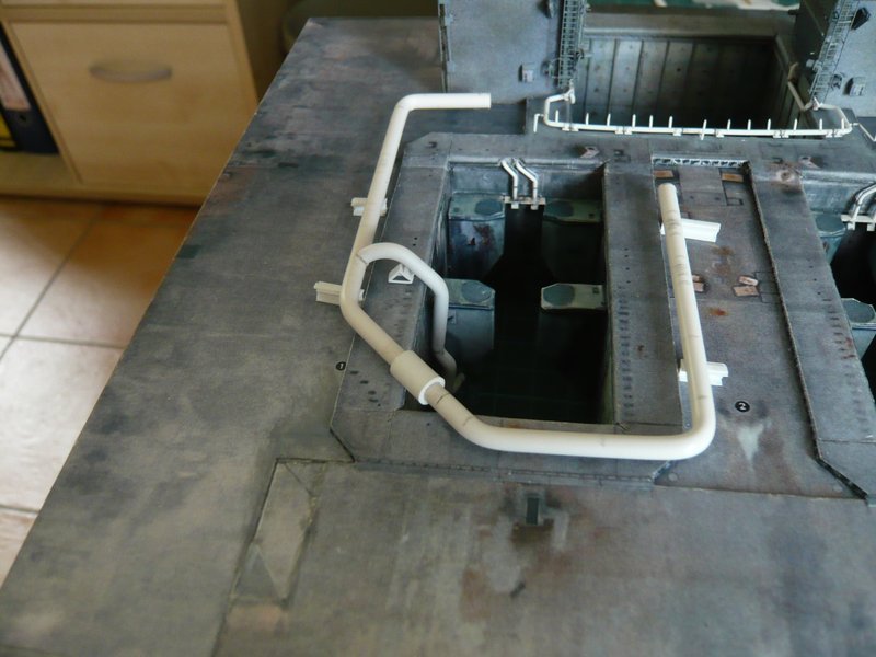
And this is the preliminary result, which can be quite impressive.

Now only the final bending til below the SRB support is missing, for which I still have to determine the distances and dimensions.


Source: NASA

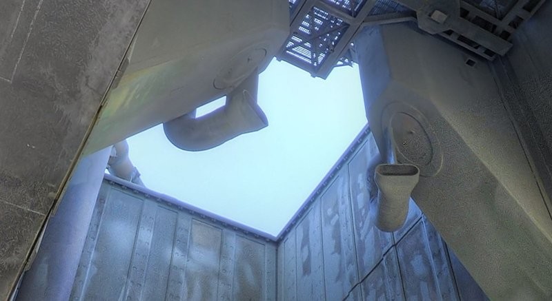
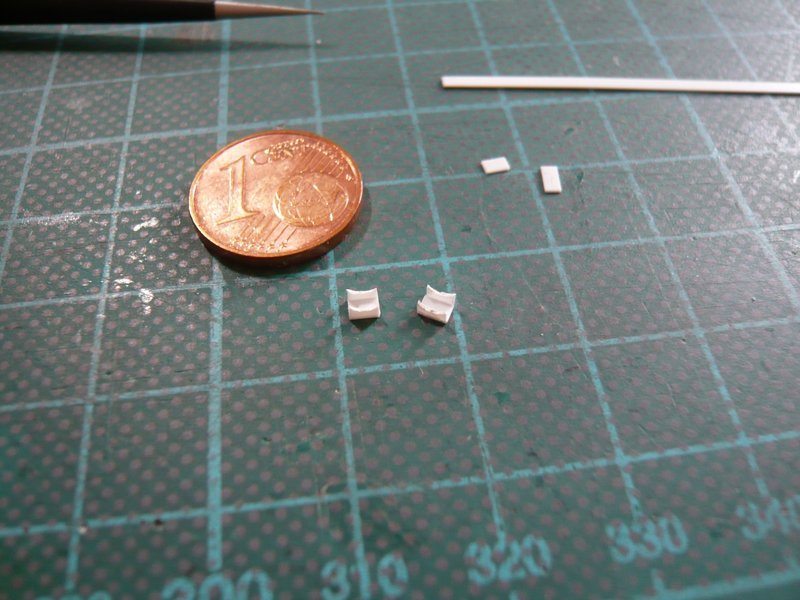
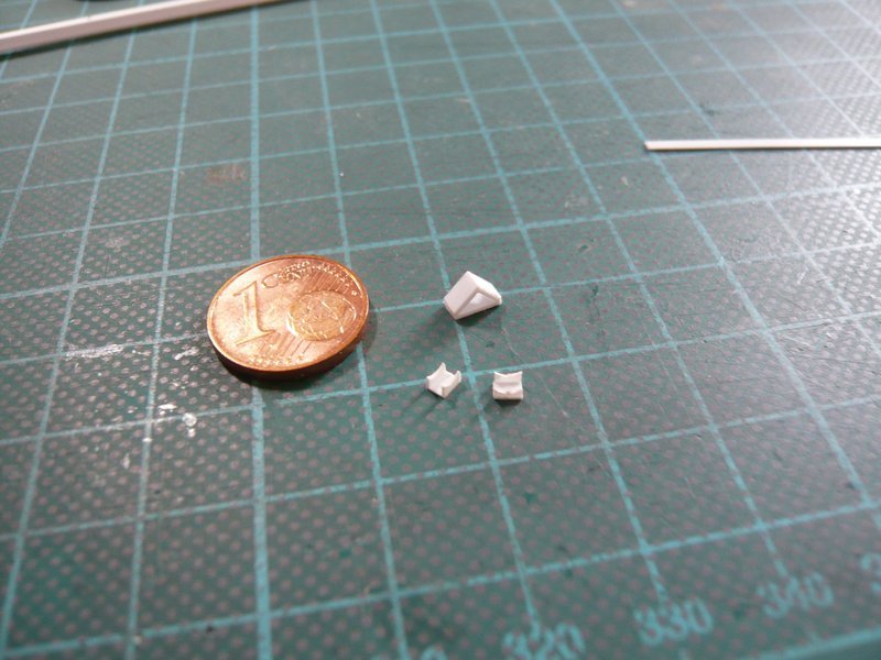
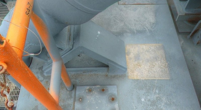
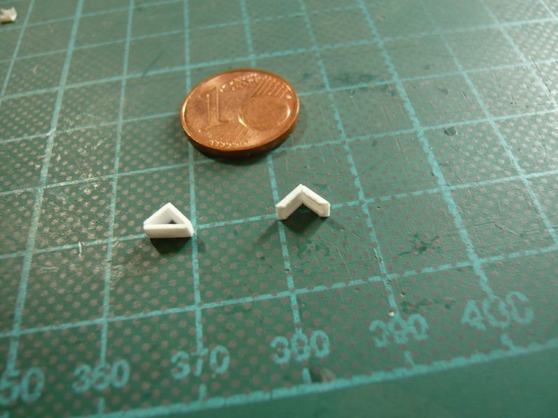
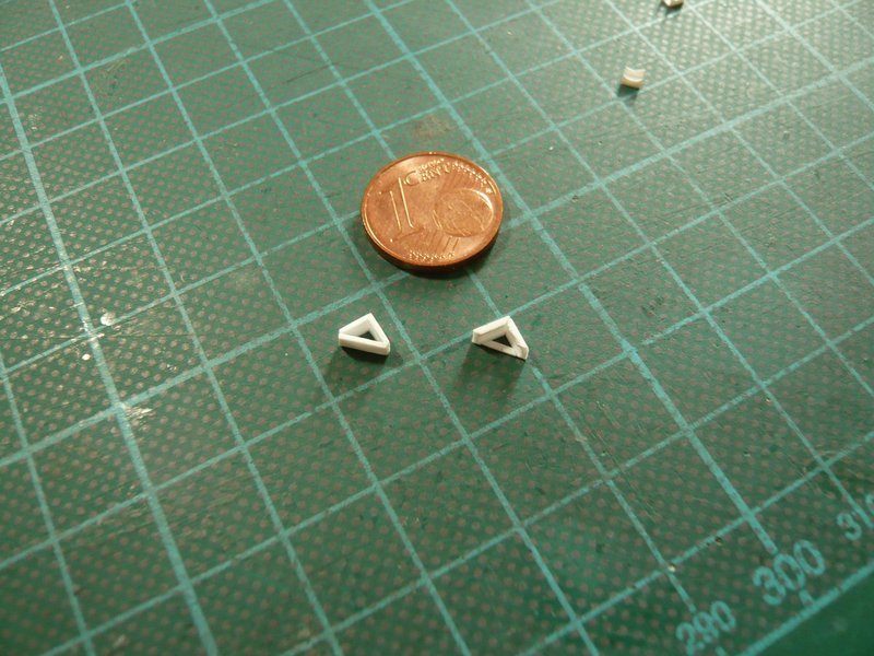
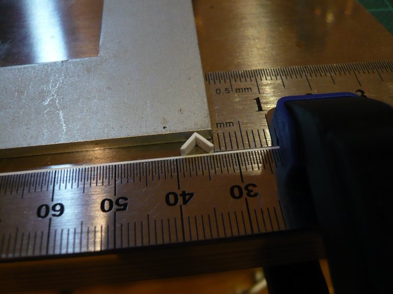
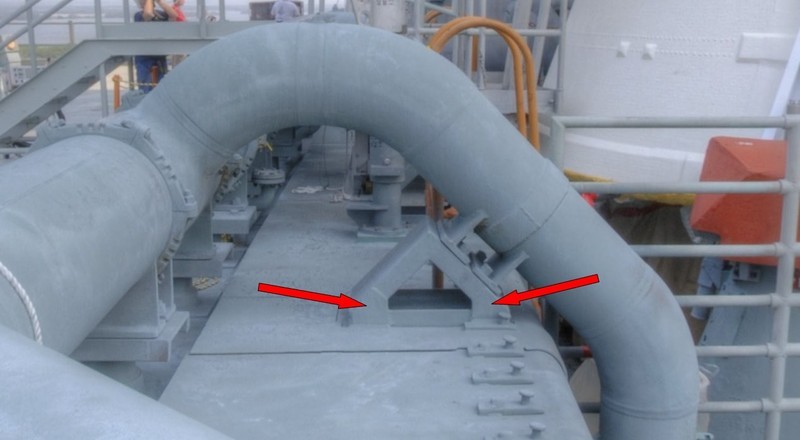
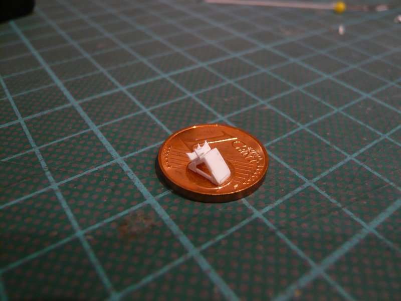
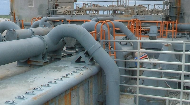
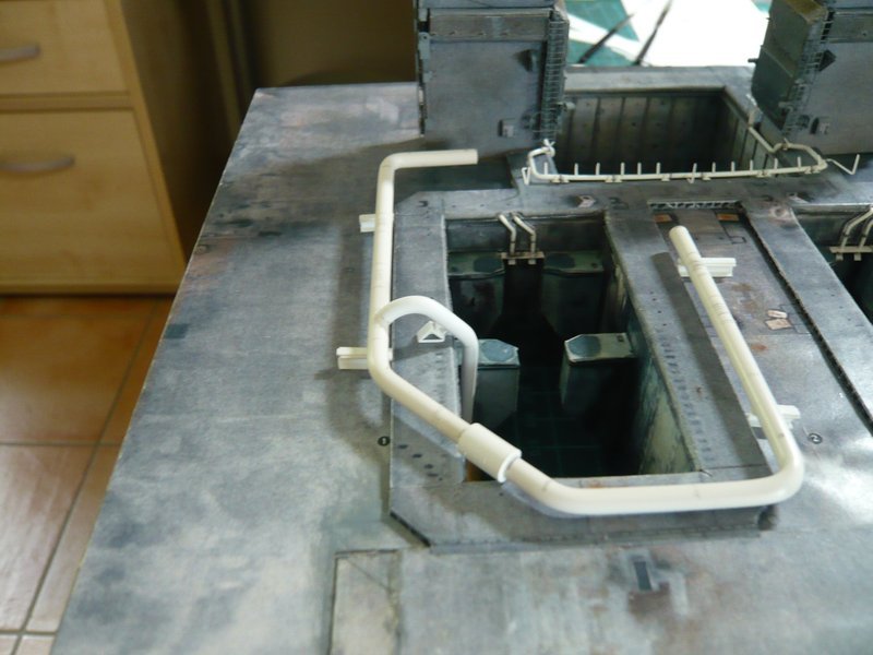
And now a short outlook at the initially mentioned pipe supports under the outlets.


Source: NASA

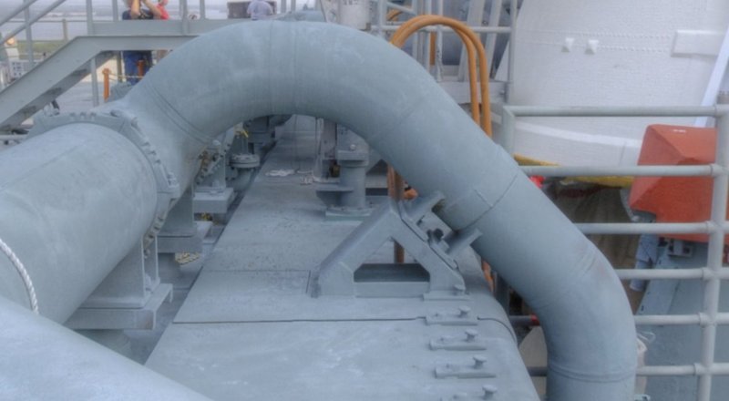
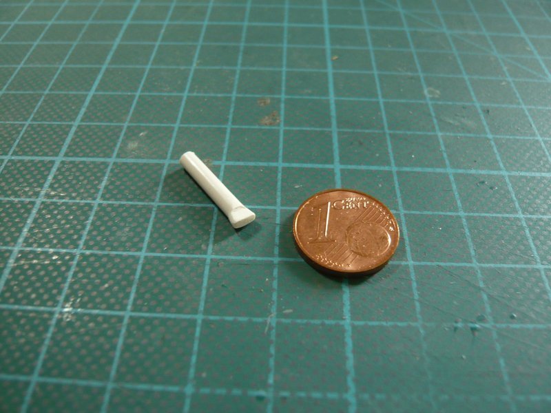
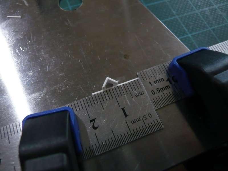
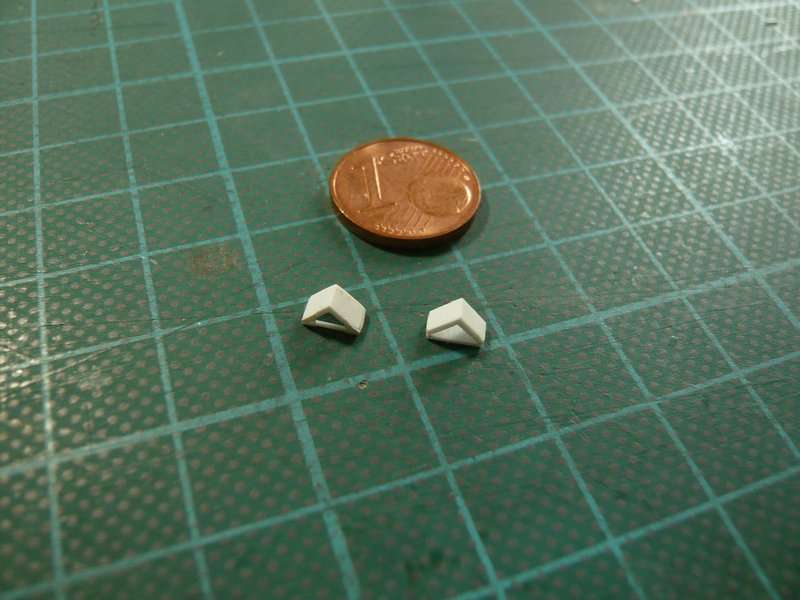
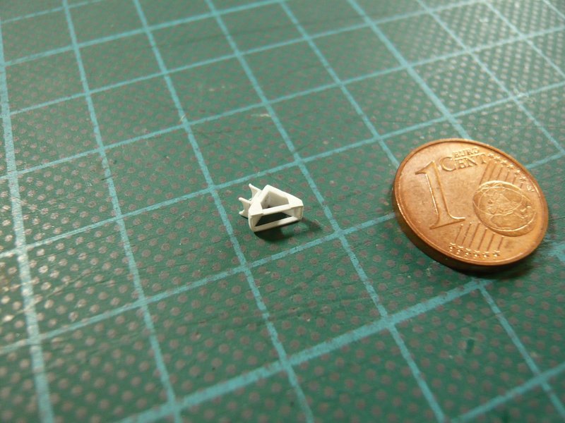
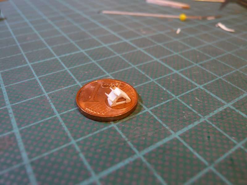
In this image all looks again relatively easy, the triangular base as well as the sickle shaped brackets, similar to those at the supports for the 24’’ ring line. But if one now outlines the real proportions in model scale, then this part shrinks considerably.

And so I will let it go at that for today.

4 Likes

Great update and it has to be said again, superb attention to all these intricate details … and the bending jigs are brilliant !!

2 Likes

Thanks John for your appreciative words.

Yep, my idea with the Balsa jigs in combination with the pins was really brilliant, without them these bizarre bends wouldn’t be possible.

And Balsa wood is in addition easy to work with and is light and stable. That’s why I will also use it for my diorama construction.

1 Like

Hello again,

I will tell you briefly what else happens, not much, but still gave it to me some new impressions and insights.

The last bending of the 18’’ outlet obliquely inwards til under the SRB Support was missing still, for which the outlet again was firmly clamped in with balsa boards,

and was then bent in the hot air stream.

Then I have the bent outlet temporarily hanged in the chamber and viewed from all sides, as well as compared with the reference pictures, whereby I have noticed a few things.

Thereby the 18’’ outlet (Ø 3 mm) optically seems to be a bit too small compared to the 24’’ ring line (Ø 4 mm), which is why I still will do a second attempt with an Evergreen rod Ø 3,2 mm. Sometimes making a few tenths already something.

Furthermore the top arc is to me altogether a little bit too round, because the slant to the vertical part is too little marked.

And then the last bending til below the slant of the SRB support lies a little too far below, namely further than it looks in the picture, what I’ll check in more detail.

Finally, I have tried to scratch the outlet opening at the end of the line,


Source: NASA

whereto I have simply flattened the 3 mm rod with pliers, which would almost suffice already.

Okay, that’s all not earth-shattering, but maybe I could make it still a bit better.

4 Likes

Hello everybody,

and for these pipe supports at the rear 18’’ outlets I have now tried some variants.


Source: NASA

Here are some Evergreen profiles that come into question. And these are from top to bottom a 4 mm angle profile, a 2,5 mm channel, and the same profile, in which I have sanded the lateral webs in the front region down to a profile height of 0,75mm.

To the right already the first four sickles for pipe holders of the upper parts are ready,

which I have fastened again in proven manner and have glued with MEK.

And this is initially the easiest variant for the triangular substructure, whereto I have glued a 4 mm Evergreen Angle onto a 0,5 mm base plate.

But as one can see in the picture, the substructures are actually open at the bottom and have two thin base struts.


Source: NASA

Therefore I wanted to try a downwardly open variant, and used the sanded down 2,5 mm Evergreen Channel. But therefor one has to deal immediately with miter cuts, which also must have the same length, what is easier said than done.

And then the slanted struts (0,25 x 0,75 mm) have to be glued, but this one is still too wide and is located too far up, since the angle must be sitting on the struts. Therefore, an Evergreen Strip certainly should be better suited 0,25 x 0,5 mm.

So I’ve been thinking about another possibility and have chosen this strip 0,25 x 0,5 mm for building of a thin frame.

But after the first two frame strips were glued laboriously separately, I had to realize that this could be no viable method obviously.

But then I benefited that this thin strip can actually bend without breaking, which I have previously already experienced with similar strips.

So I have removed these two strips and started a new attempt, in which I wanted to try to bend the strip into a small frame and to glue under the angle.

Although these are only tiny contact points, but with MEK it works well, but if they can withstand the bending, remains to be seen.

And with this bending it should be continued tomorrow, thereby I should benefit from another detail of these supports, which I previously wanted to leave off.

3 Likes

Hi there,

and thus to this support detail, although this every now and then was caught in my eye, but it was not previously appeared as so important to me and I therefore omit wanted. That are these welded stiffening plates, which are barely visible in this image of MLP-3.


Source: NASA

In this photo from the MLP-2 one can see them more clearly, but also recognizes that there are obviously different forms.


Source: NASA

And these plates vary actually from MLP to MLP and are themselves neither uniformly on a MLP on all supports, nor on the front and back of individual supports, what can be quite confusing at the moment.

Therefore, I have henceforth concentrated myself only on images from the MLP 2, and there are also supports (the left 18’’ outlet) mounted on the top which still have an additional third stiffening plate.


Source: NASA

And these plates I have availed for bonding a filigree frame of a 0,25 x 0,5 mm strip, because without one, though minimal, bearing surface it would be probably become nothing.

For the plates at the base I have cut narrow strips of 0,1 mm Styrene and glued it onto the angle with MEK.

And on these strips, I have glued the frame strip (0,25 x 0,5 mm),

then I’ve cut the overhanging strips. And then, at the corner followed the first bend and bonding of the frame on the narrow side, etc. all around.

One just have to pay attention to solid support surfaces, then it will work, even if it is rather fidgety.

After this also the second Support variant with an open bottom was finished and is presented here with the first variant. Now may be glued even the plates on the back.

And now also the top part with the sickles was glued, thus the support would be completed.

And the fitting of the first support on the MLP should not be missing.

Accordingly, I will stay with this variant, since the envisaged channel variant therefore has become superfluous.

8 Likes

Hello friends,

as I had already indicated, with the first bend test of the 18’’ outlet I was not completely satisfied, because the upper bend downwards to the kink total still was too round what was due to the template.

In reality, the piece above the support is until to the edge of the Blast Shield but straight, as one can see here.


Source: NASA

In the meantime I’ve also bought Evergreen Rods Ø 3,2mm.

In order to get the bend at the second time right, I have beveled the slight arc of the template, as well as chosen a different bending sequence and initially bent this kink only, whereby the top piece is straight.

And this straight piece now I have extra strongly fixed, so that it during the subsequent bending of the upper arc also remains straight. That was the whole trick, and this has worked actually.

Then I have tested how this looks in the SRB chamber, and I must say, much better.

Then followed the lower bendings, for which everything was fixed bombproof again,

what was worthwhile,

as becomes clear by comparing the two outlets. The first outlet was downwards even a bit too long, what I have also corrected.

And with this fitting now I’m more than satisfied,

and can finally give rest. And so I will now also scratch the remaining three of these outlets even before then follow the outlets with the tapers.

And now my friends it’s time to make a little break for wishing you all .

5 Likes

Hello everybody,

I hope you had a great Christmas!

Meanwhile I have bent into shape the remaining three 18’’ outlets and have tried, to make them as congruent as possible. While this is relatively easy with the upper arch using the template,

but the lower bendings are more difficult because of the short distances, because one needs suitable balsa pieces and must clamp them multiply. And then one has to make absolutely sure that one must bend the last bending of the two inner outlets laterally reversed.

But that looks at least so far not bad. Now only missing the outflow openings, at which I’m still fiddling about.

Then I have prepared two templates for accurate and especially stable positioning of the ring line above the SRB chamber because so far the test fitting of the disposals were pretty stressful, because the ring line is often slipped away from the support dummies.

Now the ring line sits perfectly and relatively stable over the chamber, whereby the fitting of the outlets and later their installation becomes much easier.

Well, and now the outlets between the SRB Supports come into play, which are rejuvenating downward after the top 18’’ arc to 12’’ (Ø 2 mm).


Source: NASA

This I want to do, by bending the upper arcs according to the template and then the lower angled 2 mm outlet will be attached separately. And this transition is then modeled with Apoxie Sculpt.

I think at least that this technique should provide more uniform transitions than with the hot air draw technique.

And this I try then next time.

3 Likes

Hi folks,

before I have started with the dimensioning of the parts for the outlet from Ø 3,2 mm to Ø 2,0 mm, I have looked some of the details a little bit closer.

As you can see in the image, the bends of the outlets are about at the same height,


Source: NASA

and the geometry of the bends seem to be about the same.


Source: NASA

As one can see in this picture, the transition region to the tapering lies approximately over the top of the triangular pipe support, and the vertical 12’’ outlet is scratching even at the SRB-Blast Shield.


Source: NASA

And since this outlet is directly running to the shaft wall downwardly, would this 18’’ bend actually be somewhat narrower or shorter than the bend of the outlet behind the SRB support with no taper. Accordingly, the pipe supports should be about the same size, I guess.

And this outlet I have now composed of two parts. The shape of the upper bend (Ø 3,2 mm) is identical to that of the previous outlets and was cut off at the point above the triangular support. And then the angled part of the taper was attached (Ø 2,0 mm), whose transition still will be modeled with Apoxie Sculpt.

The image shows also the first attempt to indicate the outflow opening at the end of the pipe.


Source: NASA

For this I have drilled out the 2 mm rod below with Ø 1,6 mm and removed one half of the “tube”. The resulting opening becomes still beveled and closed downwards with a small disc. And I mean that one can definitely accept it, right?

And this is now the test fitting of the tapered outlet at the ring line. But as one can see, unfortunately, does not fit properly so, which indeed would be too good.

The upper 18’’ bend protrudes too far inwards, whereby the support does not fit under the 12’’ outlet, which also is not snug enough on the shaft wall. That’s why I have to shorten the inside of the bend a little bit, whereby the outlet is coming closer to the shaft wall. Thereby the support also should fit better under the tapered part, I hope at least.

So I have further experimented and both the 18’’ bend as well the 12’’ outlet slightly shortened.

And this is the preliminary result. The outlet has thereby indeed moved a bit closer to the shaft wall,

but the bend protrudes still too far inwards, whereby the clearance for the support is still not enough.

Therefore, the arc must be estimated shortened by 1 mm, then it possibly could fit better.

Step by step one gets closer …

Here is the result after the shortening of the bend.

And lo and behold, now the support fits better.

At the front outlet this support inevitably is missing now, whereby this is not fixed properly and logically sagged down too much.

Thanks for watching and bye for now.

7 Likes

And Happy Xmas/New Year to you too. Literally mind-bending brilliant work, if there’s ever a Scratch-builder’s Hall of Fame you’ll be my nomination, along with Stickframe. And I’ll also nominate you for the Uri Geller medal – provided you perform a successful high-pressure water test :rofl:

2 Likes

Thank you my friend for your kind compliments,

I’m hold on tight to my dreams and stick to my principle: Learning by doing - Nothing is impossible.

The STS-6 Medal for Stamina 1st Class I have already awarded myself.

5 Likes

Hello everybody,

if one looks at this 12’’ outlet more closely, one sees that it is still too much rounded at the kink,

which is why I have this pronounced even stronger, as can be seen right in the image.

And from these outlets I need a total of six pieces that I need to scratch now.

Since the 18’’ arcs of these tapered outlets but are slightly narrower than those of the other four 18’’ outlets without taper, I had to create a new Balsa template for bending.

For further handling, it was skillful, initially to file the rounding at the left end of the arc and only then to remove the right end of the arc.

How now shows the test fitting in the next image, the new arc is but still a bit too long and still needs to be shortened somewhat, so that the outlet comes closer to the shaft wall.

And then I have tried to also represent the outflow opening opened at the 18’’ outlets, whereto I drilled the end with Ø 2,5 mm and sanded a bit at the inside.

Then I have heated the opening and pressed together in the sliding caliper.

And this opening really appeals to me actually completely well,

especially as it looks more realistic than the first attempt.

Maybe I’ll find even a slightly larger drill to reduce the wall thickness a bit more without having to smooth the opening yet.

3 Likes

Another brilliant update showing those superb ways you overcome the issues that crop up and then producing nearly exact replicas of the real items … Really awesome and inspiring work.

2 Likes

Thanks John for your nice compliments.

This is my tendency towards perfectionism. Curse or blessing?

And the brilliant panoramic images by John O’Connor as an indispensable source are very helpful.

3 Likes

Hello everybody,

after the first training, I have now begun scratch-building the six outlets with the taper from 18’’ to 12’', which consist of two parts.

Thereto at first I have bent the 18’’ arcs with my new Balsa template, and then the simple angles of the 12’’ outlets. The shortening of the arcs happened initially based on my sketch, but the comparison of the arcs showed slight differences in width.

So I had to be little more exactly when shortening the arches, wherefore this upper stop was helpful. So the position of the arc is clearly fixed, and the shortening always happened in the same place, which has thus delivered same lengths.

Thereby the 12’’ outlets could be precisely measured and shortened, which in turn shows how important it is a defined stop.

And finally, still the test arrangement of this modified outlet, here still in the wrong place in front of the SRB support, but not too disruptive in this case. But it is just clearer than on the back of the support.

And so now to the outlet opening at the bottom that I had already tried.


Source: NASA

The 2 mm (12’') rod I have drilled below with Ø 1,5 mm, have cut the opening and beveled, and then glued a disc with Ø 2,5 mm as a final deflector. And then there’s still this little protective plate, which I’ve rounded from 0,1 mm Styrene.

And then finally it looks like this,

and would be the outlet at this point, whereby the outlet opening is obscured however here.


Source: NASA

Thanks for watching.

4 Likes

Hello friends,

in the meantime I have begun with the production of the six 18’‘/12’’ outlets.

The remaining two inner outlets differ from those six thereby that they directly rejuvenate from the 24’’ ring line to 12’’ and they have a special shape that I have to bend separately.


Source: NASA

After I have slightly shortened and equalized all the arcs (Ø 3,2 mm) one more time, now the outlets (Ø 2,0 mm) had to be drilled by hand at the bottom with Ø 1,5 mm for the outlet openings.

To drill the holes halfway centered, one has to go step by step and can not immediately start with the final 1,5 mm drill. Therefore, the center initially had to be center-punched as accurately as possible, because the drill otherwise runs eccentrically at the slightest deviation.

After that followed three bores, first with Ø 0,8 mm

and 1,2 mm,

and only then with Ø 1,5 mm.

Then the openings were cut in half with a razor blade. In doing so it is advisable to leave the blade in the cut and to cut on this the half opening with a second blade to not equal to cut off the entire opening, what has happened to me at the first time.

Thereby one has to take into account the different inclined position of the outlet openings towards the SRB center, which is marked in this image for the left SRB chamber behind the LH2 TSM. Thereby the outlets 1 and 3 are identical, and outlet 2 is the outlet with the special bending which was shown at the beginning.


Source: NASA

And these are the items for the outlets, left in the image the identical outlets 1 and 3 and the outlet 4 for the left chamber and right the outlets for the right chamber behind the LOX TSM.

Underneath lay the discs (Ø 2,5 mm) for the deflector plates and next to them the fenders (3 mm x 4 mm), which are to be rounded from 0,1 mm styrene, and the strip (0,25 mm x 0,5 mm) for the retaining strips.

Next will follow the installation of outlets.

4 Likes

Spaceman,
The work you are doing here is amazing, but it frightens me that you are using double-edge razor blades, rather than singe-edge blades. :face_exhaling:

For my own peace of mind as I watch your masterful work, please at least tape a piece of card stock over one edge! :pray: :pray:

:beer:

1 Like

Thanks Namabiiru for your nice words.

Don’t worry, my friend, I’m just gently touching her sides and I don’t want to dance on her blade.

It’s all just a question of feeling.

1 Like

Hello everybody,

and now a few pics of the assembly of these outlets.

First, I have glued the rounded little fenders with the fixing rail at the end of the outlets, and then the small baffles.

what went relatively quick.

Subsequently the arcs were glued with the outlets.

For exact alignment of the arrangement my little jig was very helpful again.

And that’s it for today already.

Now only the tapers at the transitions have to be modeled with Apoxie Sculpt.

3 Likes

Hello everybody,

the modeling of the tapers at the transitions of the outlets still can wait a bit, because the last two 12’’ outlets on the front insides of the ring lines are still missing and differ from the previous six outlets. They taper directly from the 24’’ ring line to 12’’ (Ø 2,0 mm) and have themselves no further taper, but a tortuous curved course, as can be seen here once again.


Source: NASA

As the trained eye can recognize in this picture, the upper bow however is more flattened than the two rounded outlets left besides and is also a little lower, what can be seen clearly in particular in this perspective (green arrow).


Source: NASA

In contrast, the bows of the outlets on the outside of the ring line lie all at the same heights level and are clearly rounded.

And that immediately raises the question of the dimensioning of these two outlets, wherein the difference in height is more important than the shape which can be modified from the previous rounding.

For estimation of the height difference I made the following contemplation in the penultimate image, whereby I have used the diameter 4,0 mm of the ring line as reference (yellow). Based on the alignments of the ring line and the two 18’’ bows the overhangs (red) is about 2,4 mm.


Source: NASA

Since the overhang of the flat 12’’ bow (green) results to about 1,4 mm, the height difference should be about 1 mm, which is not much, but still present.

And because a new Balsa template was required for this transition, it went with this in a proven way back to my Balsa bending bench.

And this is the preliminary result, whereby the flattened part of the bow but still seems to be a little too wide.

That’s why I wanted to bend the left bow still somewhat narrower, however without heating, which has unfortunately led to an unexpected fraction, although I was carefully.

But every now and then I have to learn the hard way too. Apparently, the plastic loses during the hot air bending its ductility and becomes brittle, which one just only needs to know, but adversity is the school of wisdom. Nobody is perfect.

Therefore here an image of re-glued and slightly modified bow, which still had to become slightly narrower.

And only when this bow fits, it will go on with the tortuous transition to the ring line.

6 Likes