Amazing, and Tim isnt wrong, you will be hard pressed to tell the difference from just looking at close up photos, it really is that good.
1 Like
Yep, John, that’s right, from a normal viewing distance, many of these tiny details are no longer or can hardly be seen. But I know they are there. ![]()
![]()
1 Like
Hello everybody,
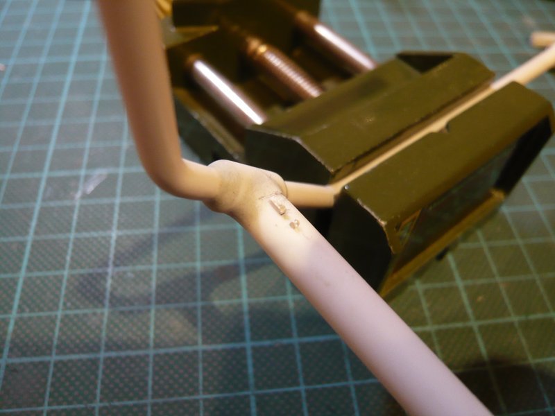
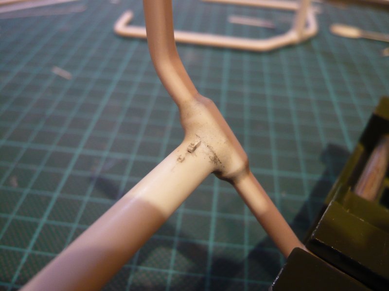
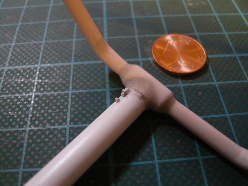
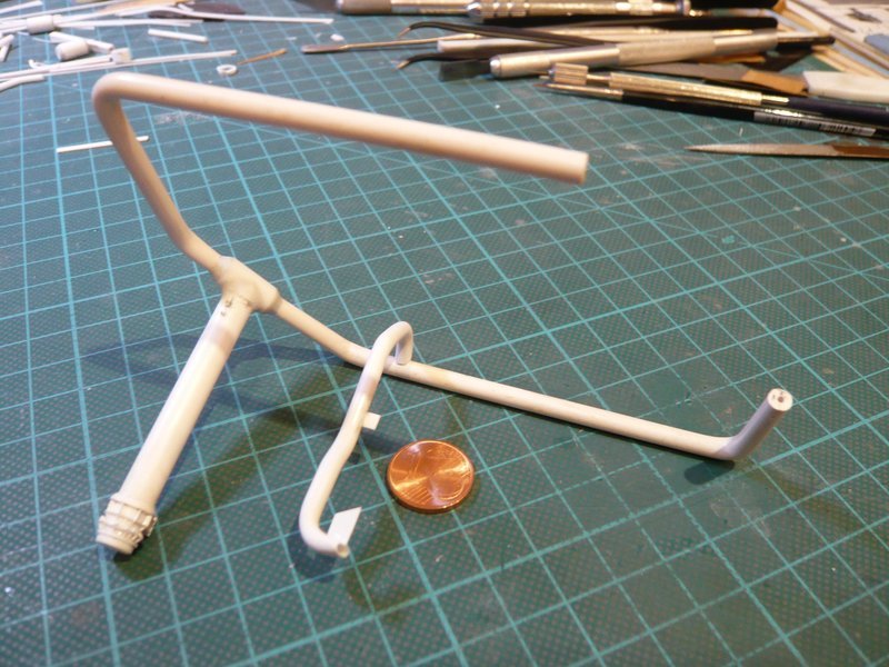
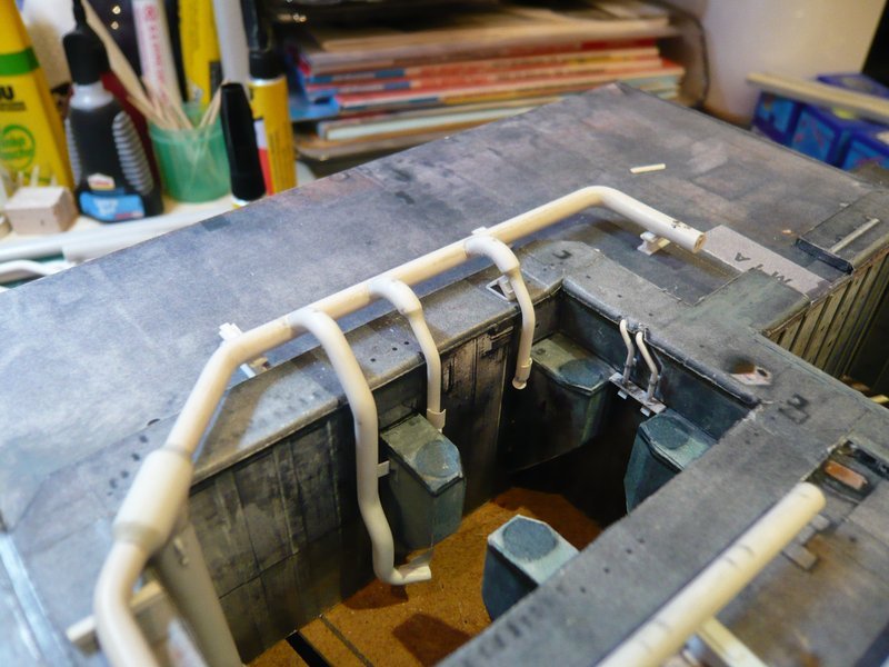
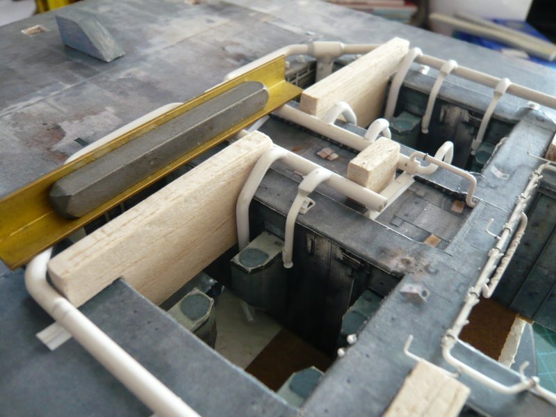
next followed the final processing of the previously modeled transitions by removing superfluous material, whereby I tried to gently approach the concave shape, which can be seen at the left transition,
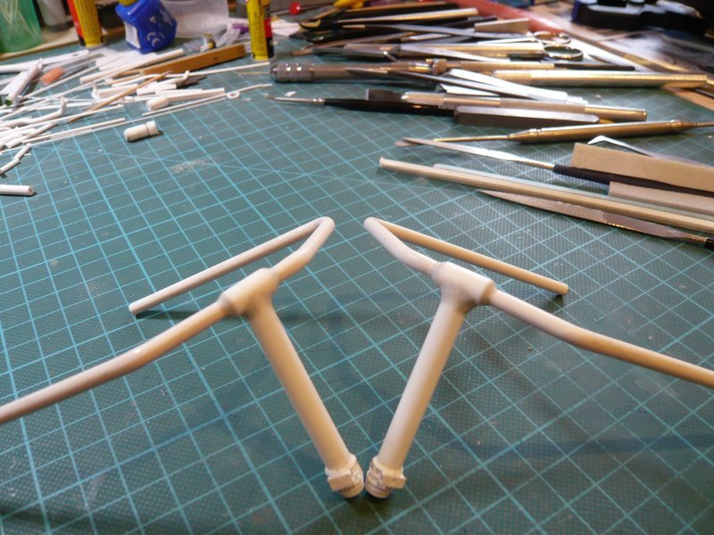
and finally at both inlet pipes. ![]()
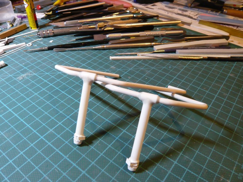
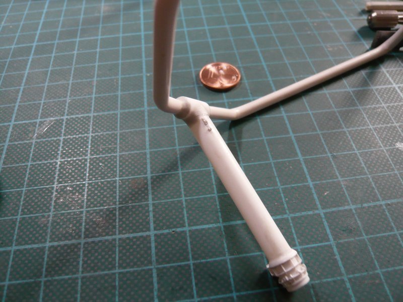
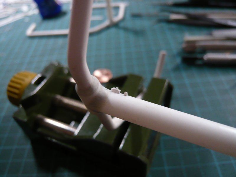
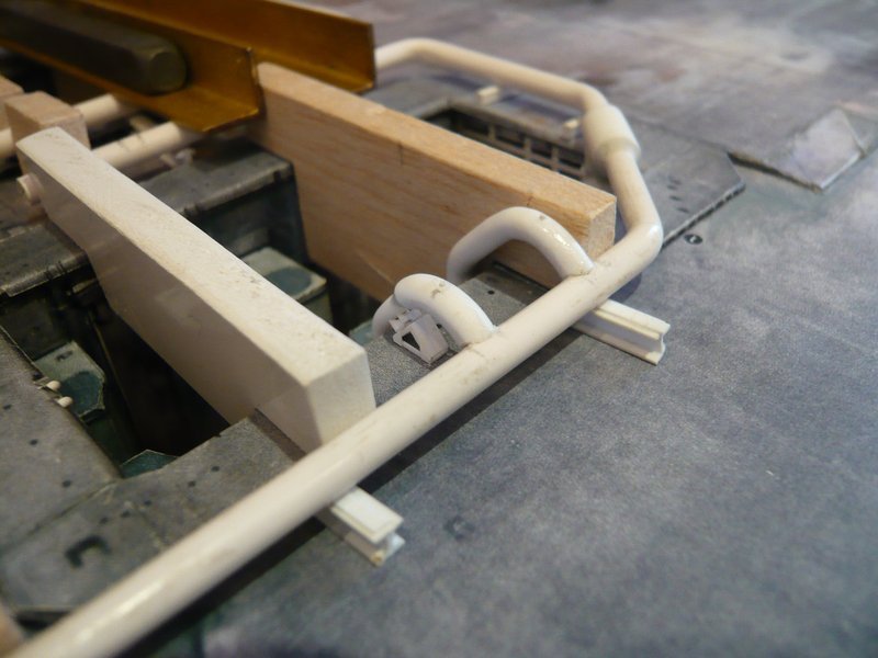
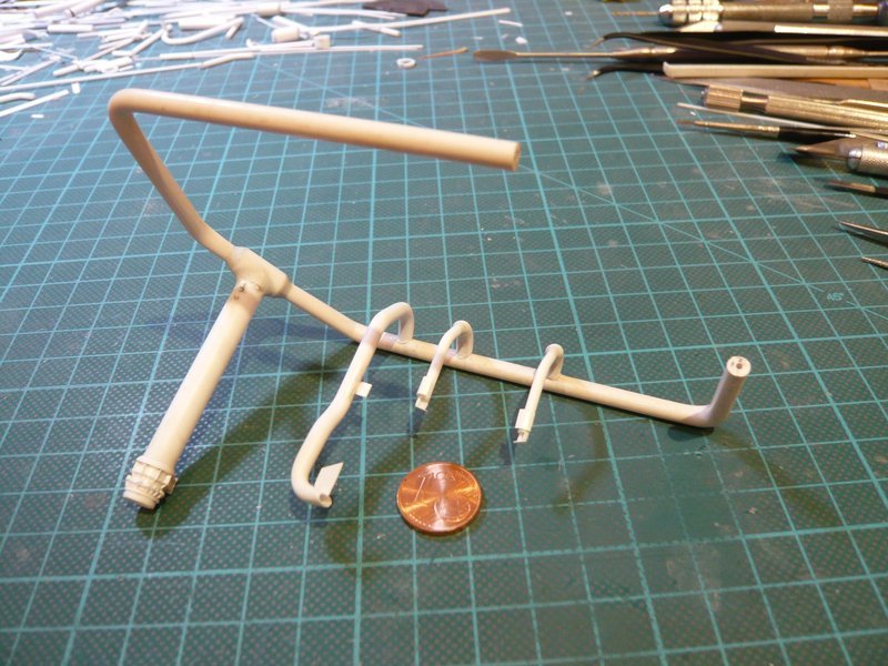
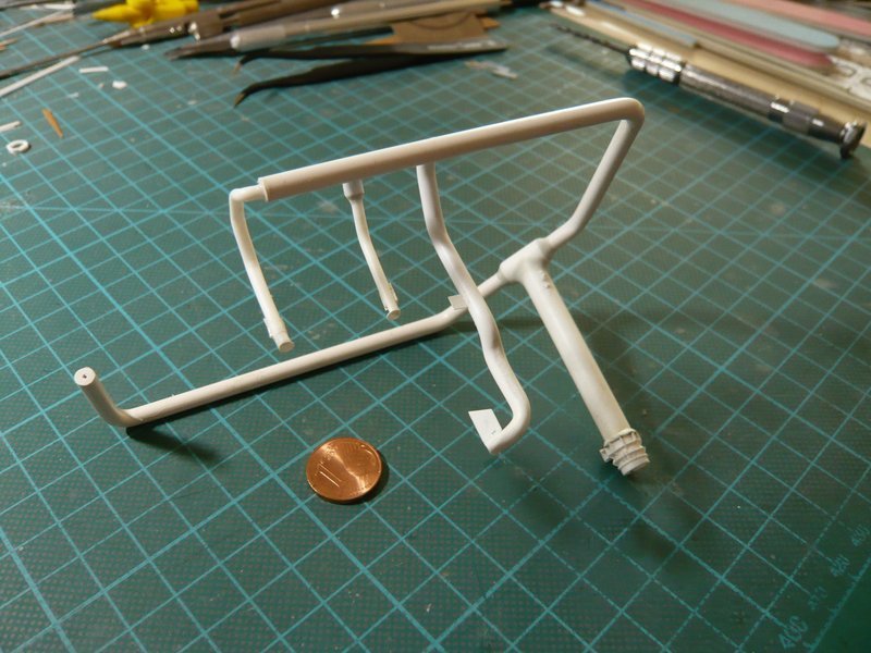
And so back to the fixing rail and guide roller at the upper end of the inlet pipes, which I have actually tried. ![]()
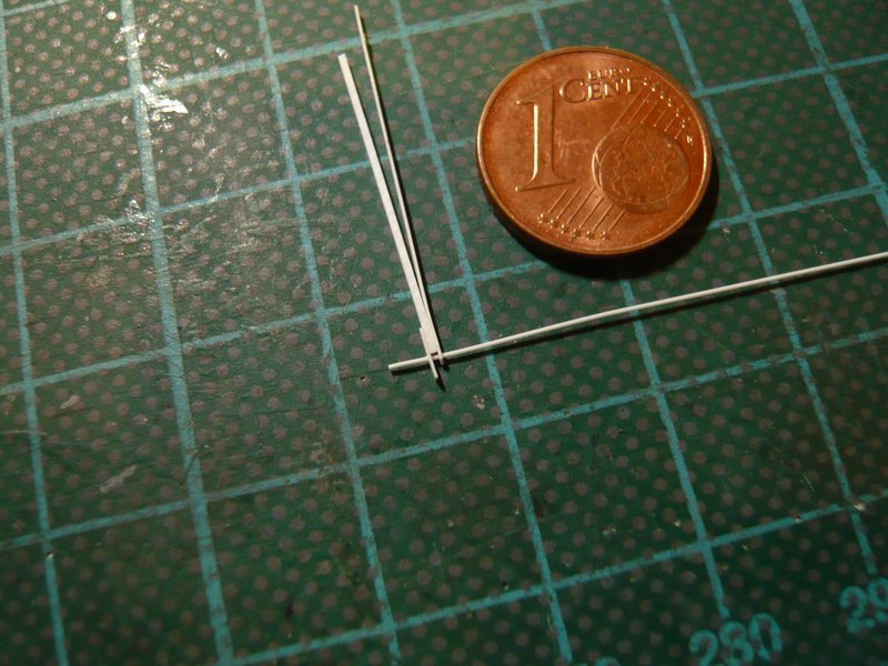
For this purpose, I used an Evergreen profile 0,75 mm x 0,75 mm for the fixing rail. For the bollard and the locking screw two Ø 0,3 mm holes were drilled and Ø 0,3 mm rods were sticked in.
And so my first prototype (2 mm) of the fixing rail looks like, ![]()
which was tested and should fit already well. ![]()
For the guide roller, I first tried to saw a central recess into a 0,75 mm x 0,75 mm profile, which is not so easy with this “width”. ![]()
It would be even more difficult to drill the necessary holes for the roll (Ø 0,3 mm) in these minimal overhangs.
That is why I re-drilled a little bit next to it and sawed the central recess a bit further, after which the bar for the roll let insert itself, albeit reluctantly. ![]()
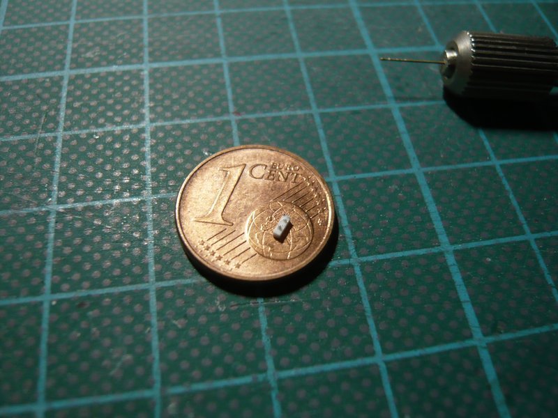
Subsequently, the rod was glued with MEK and separated off, and the overhangs were shortened and beveled.
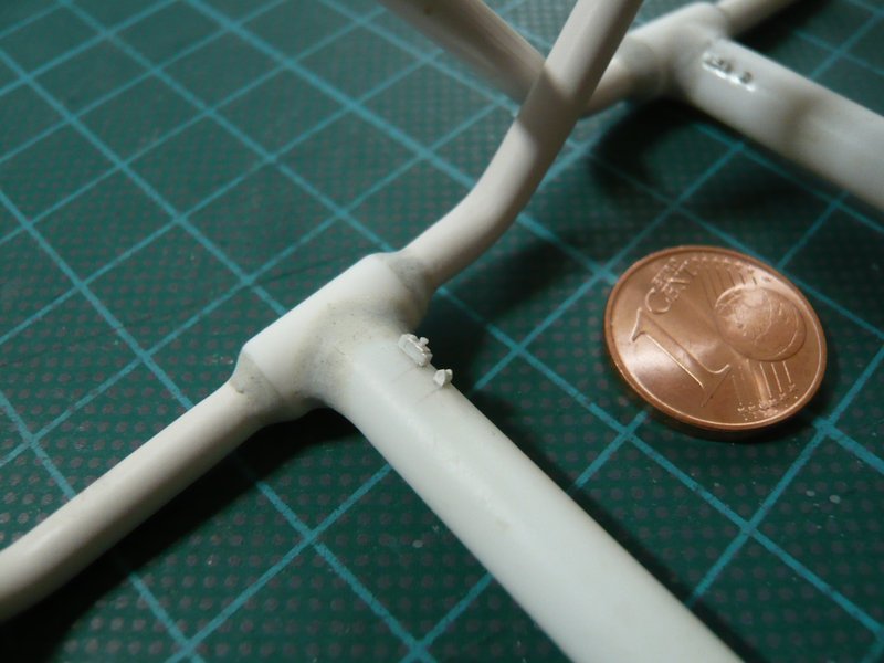
When this tiny stub was cut off, however, the mishap then happened, because after that, it was unfortunately no longer findable. ![]()
So new game, new luck, but this time according to a modified method, in which I wanted to stick two 0,75 mm wide strips (0,15 mm), which I previously had drilled, on both sides of a rectangular strip 0,5 mm x 0,75 mm (bottom). ![]()
The longer strip I have bevelled with the razor blade on both sides immediately in front of the bore to simulate the triangular shape of the side walls.
Then, the sides were threaded onto the bar, the rectangle strip was interposed and everything was fixed together between four steel scales, after which the composite was carefully glued with MEK.
To do this, it is sufficient to wet the parts only with the MEK brush as the MEK penetrates into the cracks and immediately performs its function. ![]()
Then only the triangular shape with the razor blade was cut off at the front projection, and also the rod on both sides and the rear part.
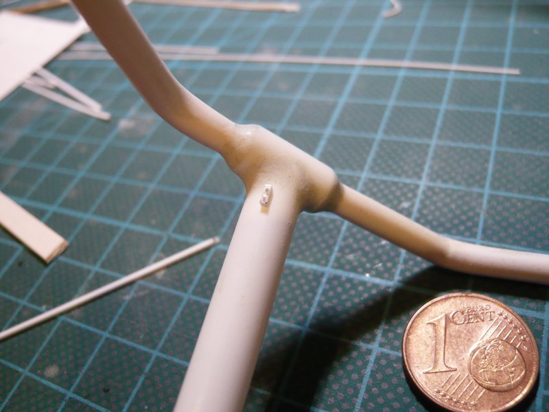
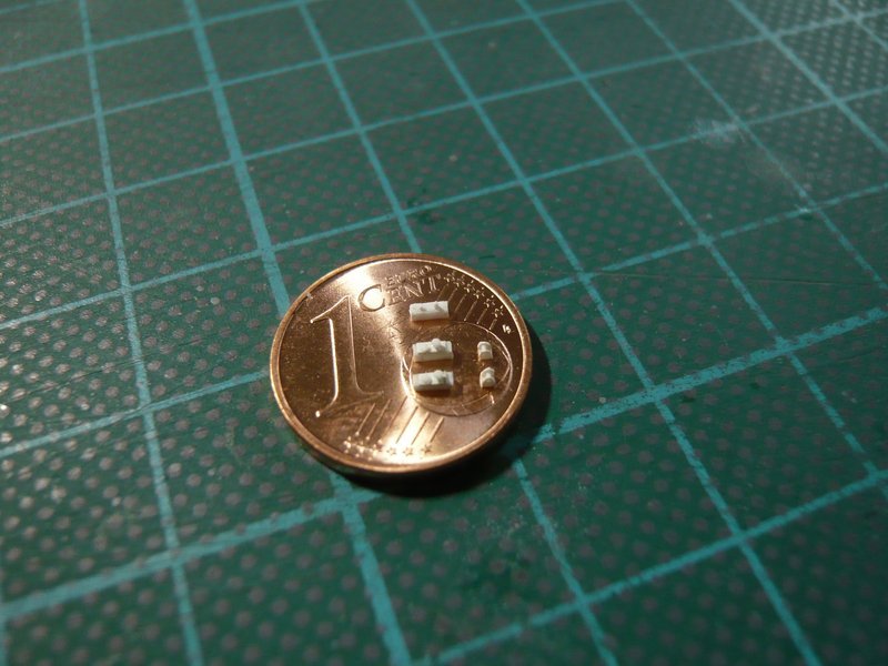
And so the two parts now look, which seems to be quite useful, ![]()
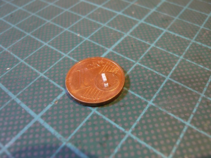
or what do you mean? ![]()
Well, these are only two tiny details, but they also had it in themselves again. The guide roller with < 1 mm lies in an area, which I really no longer wanted to scratch, but since there are only two parts, these exceptions are to confirm the rule. ![]()
![]()
5 Likes
Hello together,
no answer is also an answer … ![]()
In the meantime, I have also finished the second guide roller, which is why I am delighted, because these tiny parts can really hardly be handled sensibly, and one always runs the risk that they suddenly fly away - Goodbye forever! ![]()
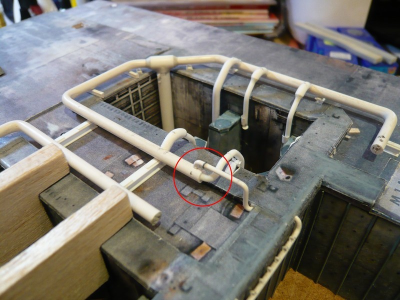
So far, so good, but with the previous fixing rail I was still not quite satisfied, since this is still somewhat more structured than my first prototype, which is why I still want to offer an update. ![]()
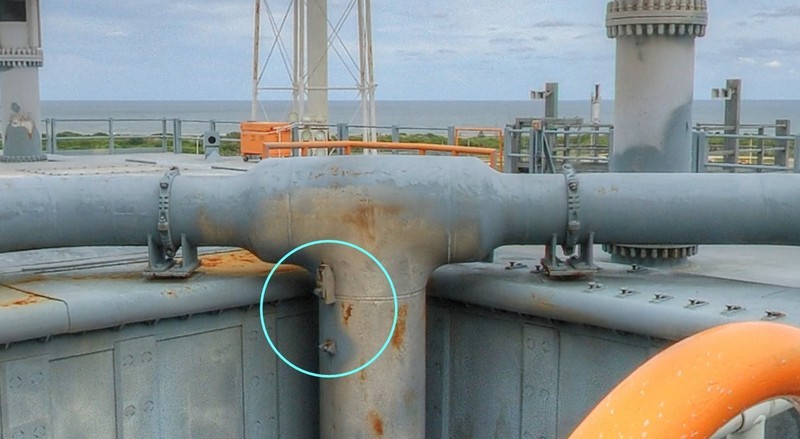
When looking closely, it can be seen that the fixing rail consists of a base body on which a clamping strip with a small bollard for the tensioning cable of the Water bag sits, whose seat can be fixed by a locking screw at different height.
Most clearly one can see the structure on this image, which is of MLP-3.
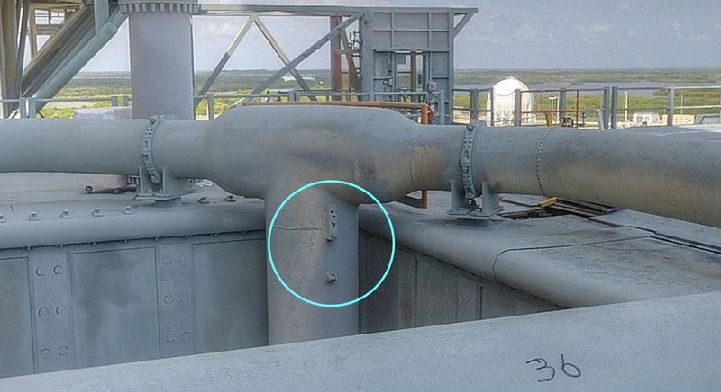
On MLP-2, however, the clamping strips had been adjusted somewhat higher.
These clamping strips are similar to those that are attached on the SRB Blast shields for holding the remaining Water bags. 
And since we are just in details, these clamping strips were initially all screwed as one can see on this image. ![]()
Later on, they were partially welded on the blast shields and the locking screws were omitted, or not, as shown in this image of the MLP-2.
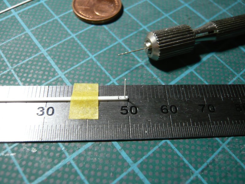
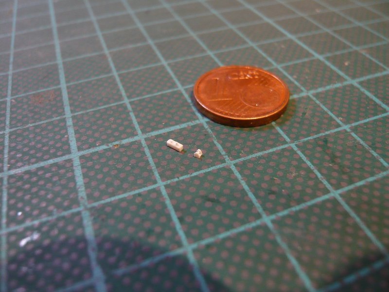
BTW, only for a basic orientation of the size, which is always interesting, these clamping strips are actually about 25 cm long. ![]()
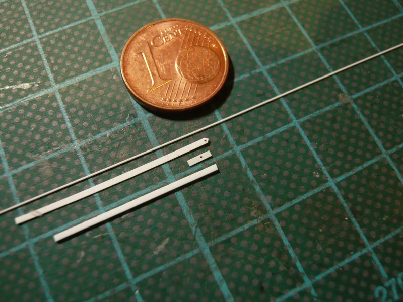
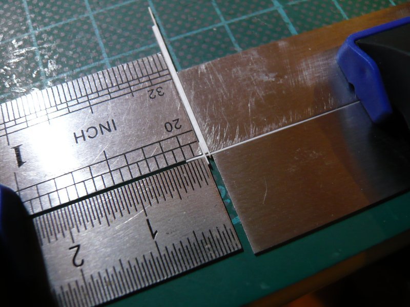
On my inlet pipe, however, this is only 1,6 mm (1:160), and consequently the clamping strip is only 0,75 mm x 1,6 mm and made of 0,15 mm Styrene, which can be distinguished a bit from the basic body.
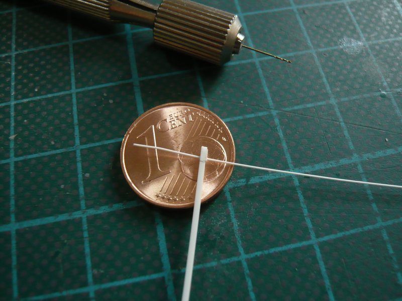
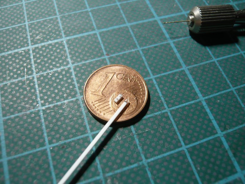
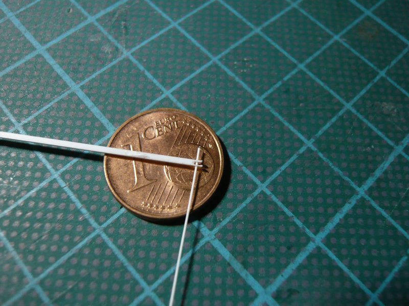
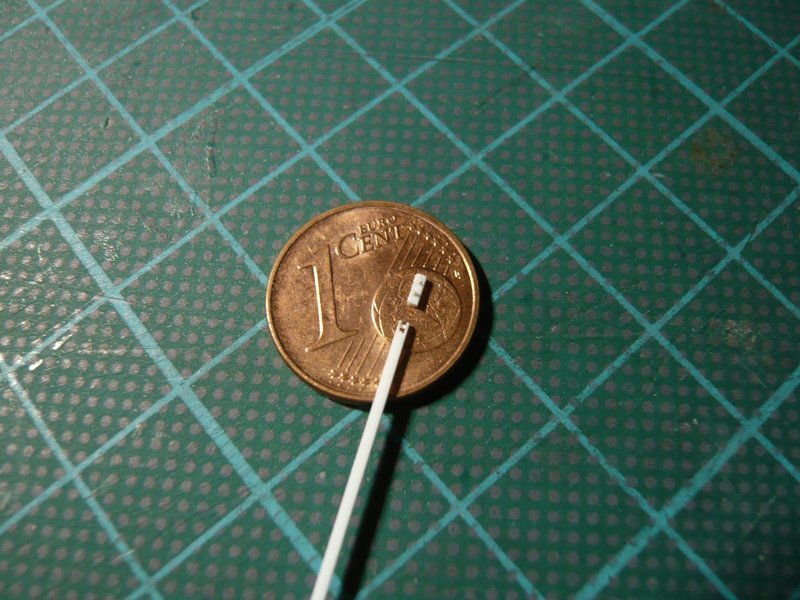
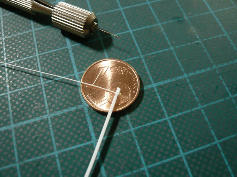
Then the small hole (Ø 0,3 mm) for the bollard foot was drilled and a 0,3 mm round profile like a thread was threaded through a needle eye. And in order to look more like a bollard, then I have glued at the end a thin disc from a 0,4 mm round profile. But to get this centrally was then again a true patience game and has worked only after several attempts. ![]()
After adjustment of the overhang, the bollard was glued with MEK,
and then the rest on the underside was cut off. And finally, a thin disc (Ø 0,4 mm) was glued on as locking screw,
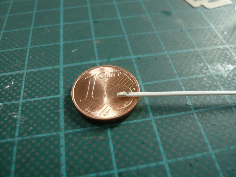
what can be seen somewhat better from the side. ![]()
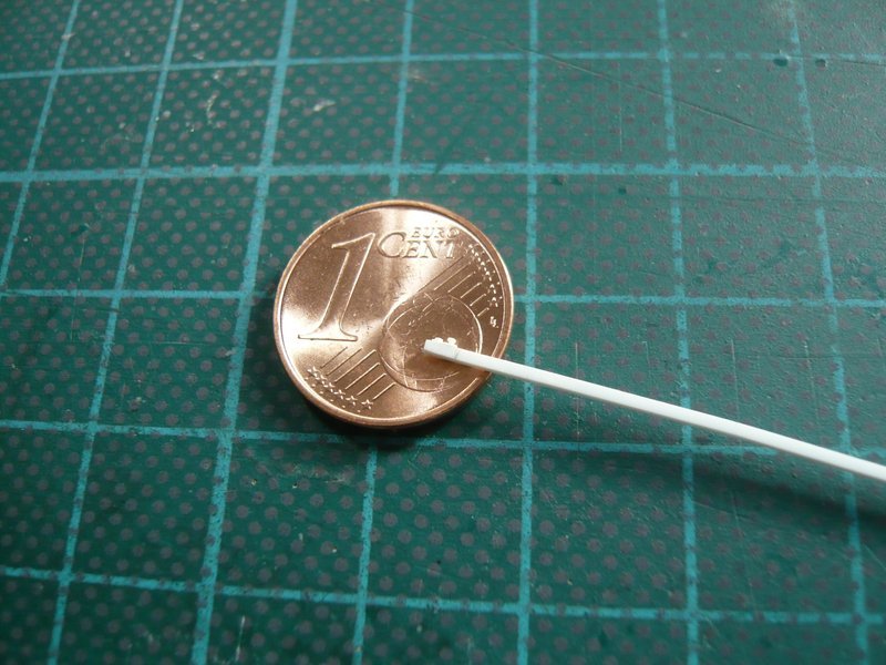
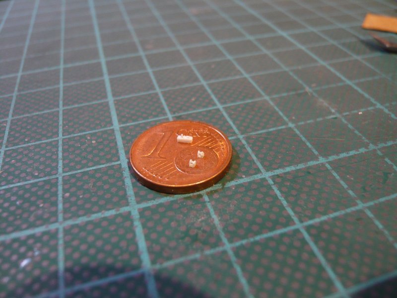
Here one can see the comparison with the first prototype,
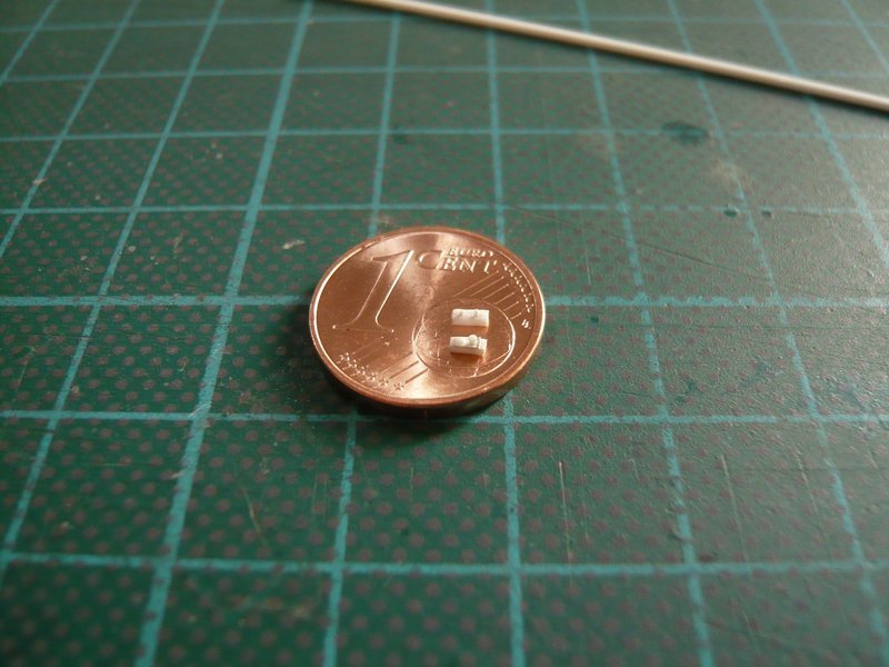
and in the meantime, the second fixing rail has also been completed so that the assembly can now follow. ![]()
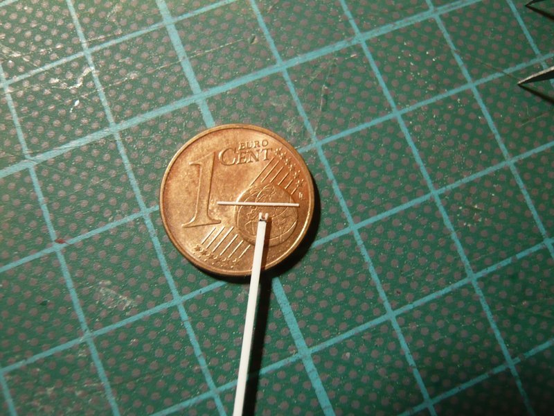
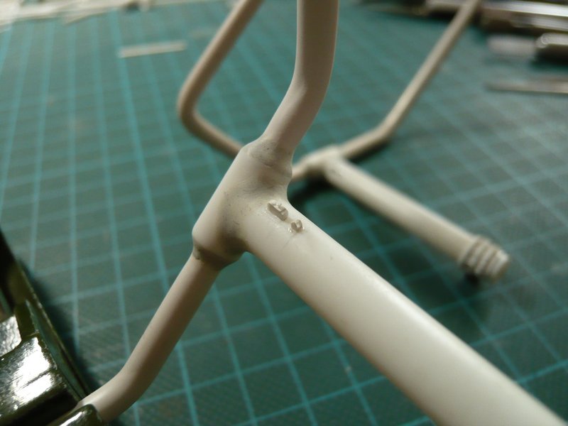
However, previously comes the test fitting and alignment of the two parts on the inlet pipe, but whose macro-images are relatively indistinct due to the too low contrast differences of white/white objects. ![]()
At even smaller distance the autofocus of my Digicam however is unfortunately at the end. ![]()
These details will become clearer only in the painted state, and as long as I have unfortunately to console you.
Maybe I can present even better shots. ![]()
![]()
7 Likes
Truly the definitive build. Your dedication to this build is inspiring.
Cheers,
Colin
Thanks Colin for your awesome compliment. ![]()
BTW, in October I’m spending a week at Niagara Falls. Unfortunately, it’s a bit far from Edmonton, otherwise I would come and visit you. ![]()
Cheers!
![]()
You’ve certainly earned the compliment and I hope you enjoy your time in Niagara.
If you have the opportunity, the Maid of the Mist boat trip under the falls is well worth it as is the tour of the power plant and the walk down the old spillway tunnel. In October I’d definitely recommend taking along a change of warm dry cloths!
I’m looking forward to the rest of your build.
Cheers,
Colin
Always love these updates for this build. The detailing never stops being amazing nor the effort and research behind the scenes. Great work as always.
3 Likes
Thanks Colin for your interesting tips, ![]()
It’s good to know that you’ll get wet despite the raincoats. ![]()
![]()
Thanks John as always. ![]()
Often into the night, which is why my friend Brian in Huntsville named me Manfred the Midnight modeler. ![]()
![]()
1 Like
Hello everybody,
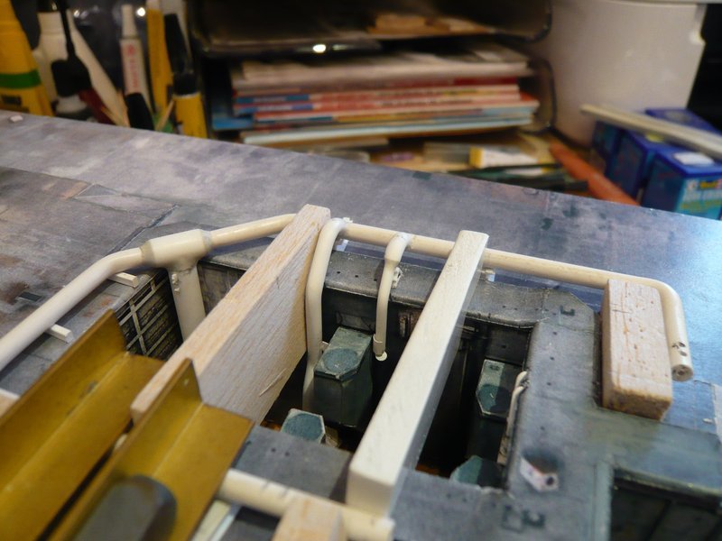
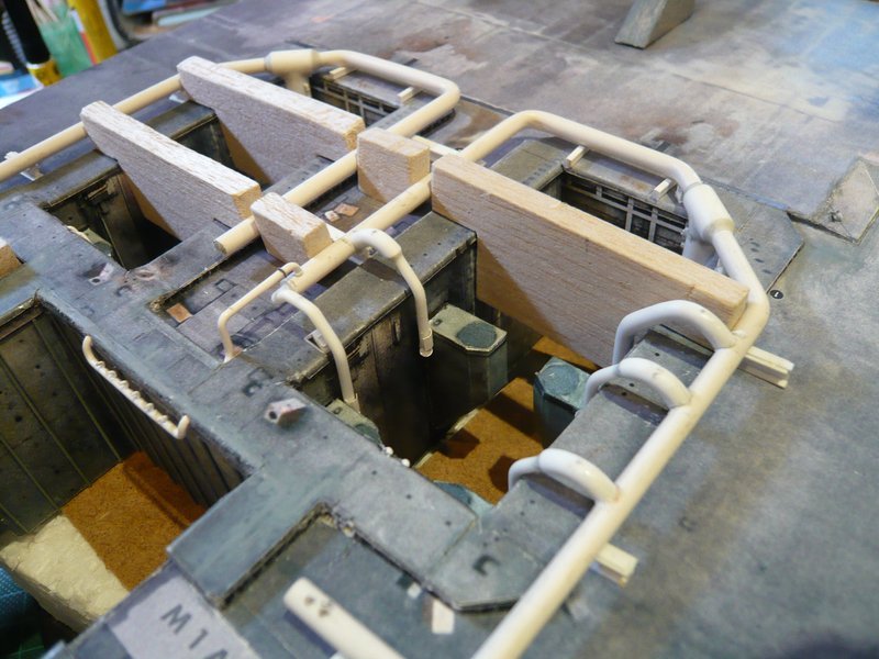
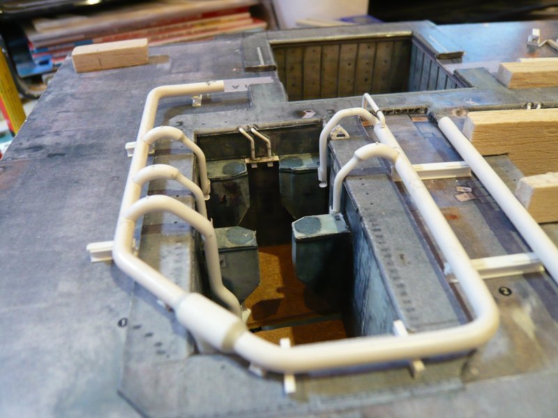
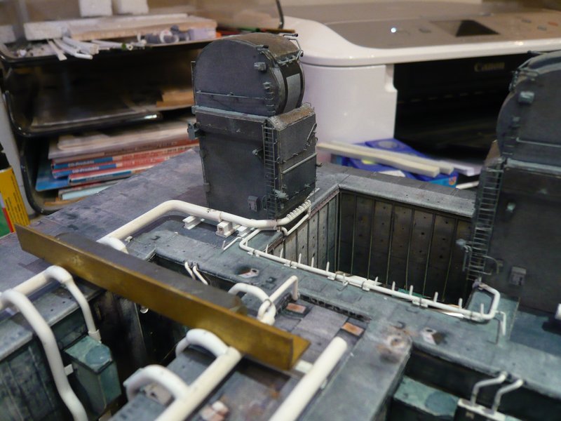
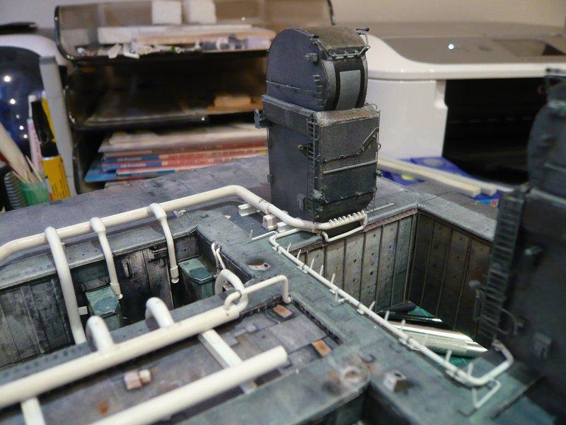
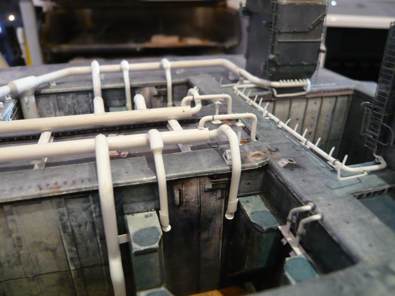
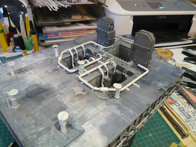
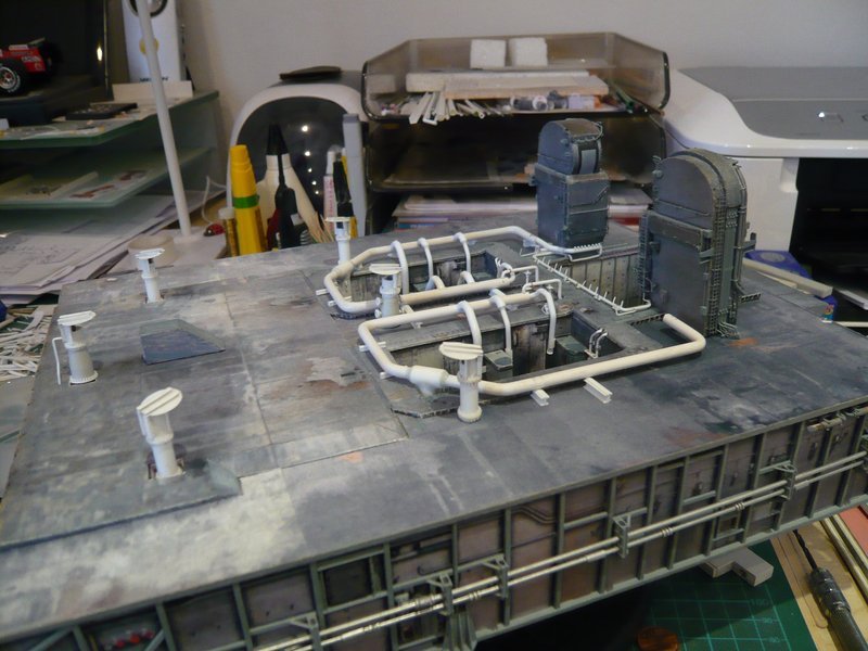
after the holding rail and the guide roller are now also glued and can no longer fly away, today still a few better pics have succeeded to me,
on which the details come out more clearly. ![]()
And here finally the first finished inlet pipe in the SRB chamber corner. ![]()
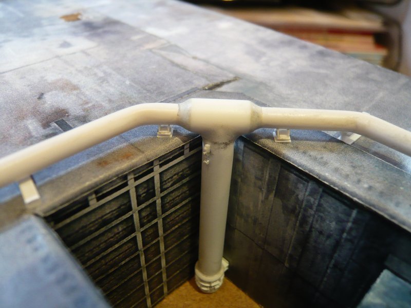
Well, the light conditions in such images are often crucial. ![]()
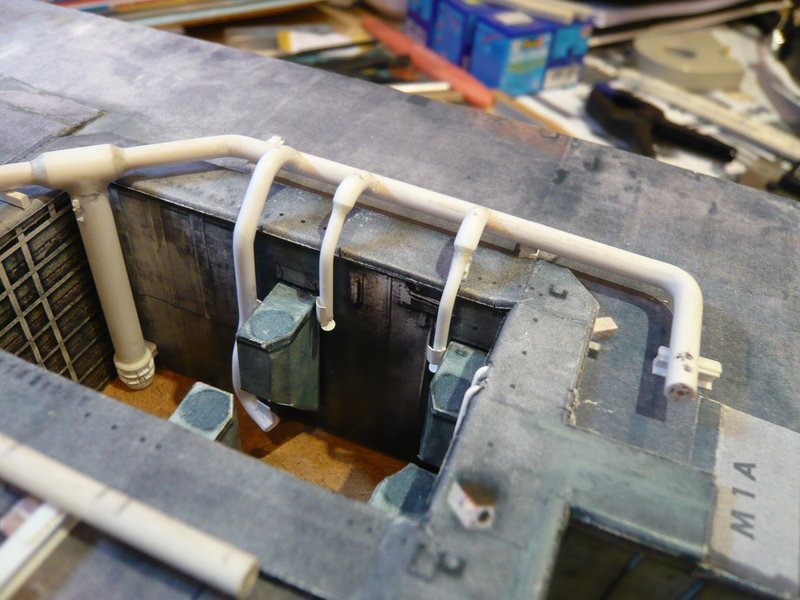
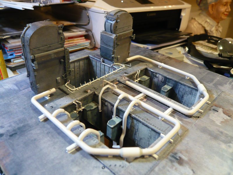
Meanwhile, the other inlet pipe has also got its holding rail and the guide roller. ![]()
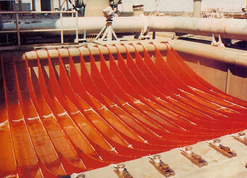
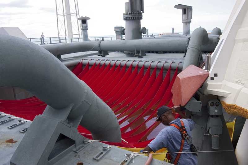
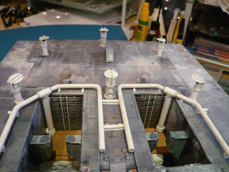
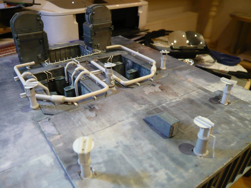
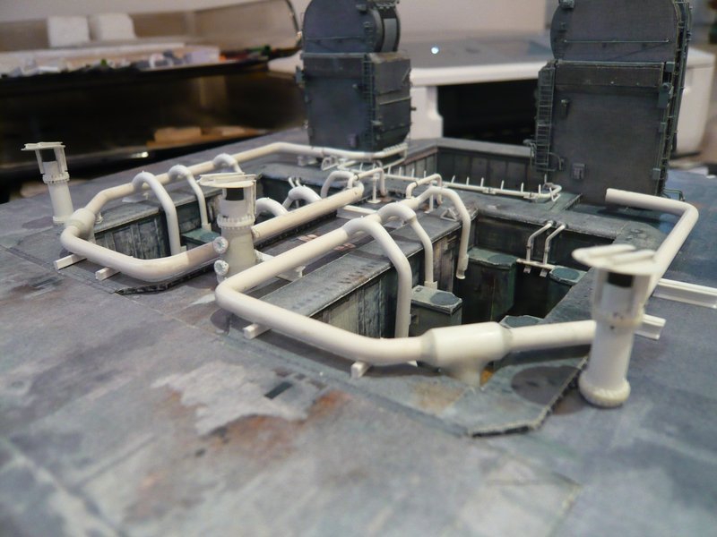
And for stimulation of the last rather dreary test fitting sceneries, I have again arranged the Rainbirds, which the picture are rounding off a bit again. But this by no means should not distract from the supply pipes and their details, although now you only see that there is something on the top, but without being able to recognize it with the naked eye.
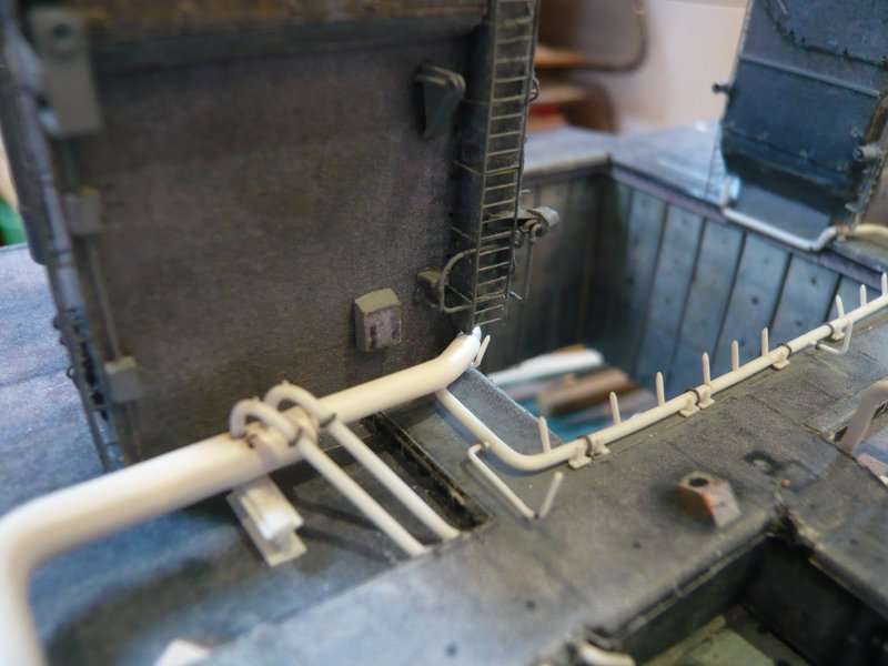
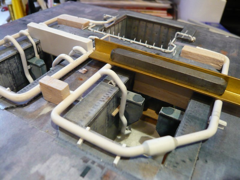
And then I have glued the first of the four back 18’’ outlets onto the ring line, which had to be back into the Balsa corset so that nothing could slip away until the glue was drying.
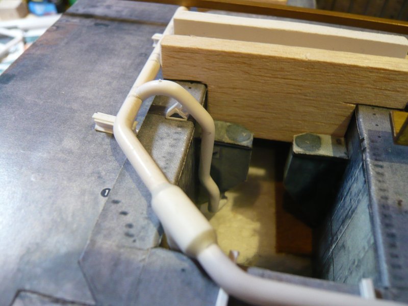
Now I’m curious whether the ring line with the outlet can now be carefully removed out of the shaft, which I hope, or whether this is prevented by the lower support plate under the slope of the SRB support. ![]() Because then I would have a problem and would have to come up with a cool idea.
Because then I would have a problem and would have to come up with a cool idea. ![]()
So long and thanks for watching. ![]()
![]()
6 Likes
I don’t know how you can create those itsy bitsy teeny weeny pieces! Magnificent.
1 Like
Hello together,
somehow I was apprehensive a bit already, but now it has unfortunately become certainty. ![]()
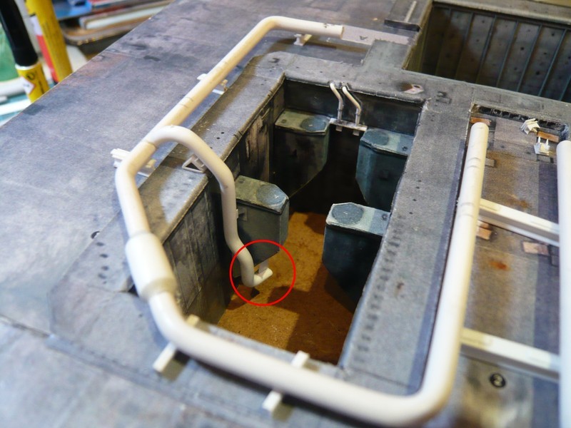
Not only the lower support plates under the slantings of the rear SRB-Supports are the hook, but the rear 18’’ outlets per se, what I could have thought however with a more thorough consideration actually before. ![]()
The ring line with the outlet can still be removed by moving it somewhat to the right and then pulling it upwards,
but this does not work any more if the other outlet would be glued in the same way onto the inserted ring line.
It basically fails at the inward ends of these rear outlets with the outlet openings together with support plates, which would make the removal of the pipe skeleton impossible. But now I must digest this bitter realization first and sleep a night. ![]()
The case is complicated, but not hopeless, and I already have some ideas, ![]() though this would not work again without minor surgery, but thereto later more.
though this would not work again without minor surgery, but thereto later more. ![]()
![]()
7 Likes
Hello everybody,
the solution of the problem is also not so easy, because I would like to model the whole pipe skeleton with all outlets also at the transitions with Apoxie Sculp and would like to install it completely after painting. ![]()
And that is why I will change my assembly sequence so far and first glue the four front 18" outlets between the SRB-Supports. Then I would carefully remove the two rear SRB-Supports as at the time when rebuilding the SRB chambers. ![]()
Afterwards I would glue the rear outlets with the support plates on the ring line and only finally at the end the two SRB-Supports glue again to the old place and adjust with the existing height stop.
As far as my consideration, which is hitherto only gray theory, but should work in my opinion. ![]()
Now I can show a few photos from today’s assembly of the next two front 18’’ outlets with the rejuvenations on 12’’ which sit between the SRB Supports.
As already indicated, I now have either to remove the rear outlet with the support plate for the assembly of the two opposing outlets, or immediately the SRB support. ![]()
Wait and see. ![]()
![]()
6 Likes
Hello together,
I have chosen the last version and the SRB-Supports carefully removed and then attached with double-sided tape as a placeholder for the assembly of the outlets again. ![]()
The 9’’ outlet I have not yet glued, because it would otherwise disturb during the modeling of the underlying transition from the ring line to the 12’’ outlet. ![]()
Up to now it fits all together quite well. ![]()
And next, it can now go on behind the LOX-TSM with the transition from the ring line to the 16’’ extension with the 12’’ nozzle tube. ![]()
![]()
7 Likes
Nice recovery. You’ll soon be ready for the Olympic qualifying 3D puzzle championships! ![]()
Cheers,
Colin
1 Like
Thanks Colin for your nice compliment,
the show must go on, it’s still a long and winding road. ![]()
![]()
1 Like
Hello everybody,
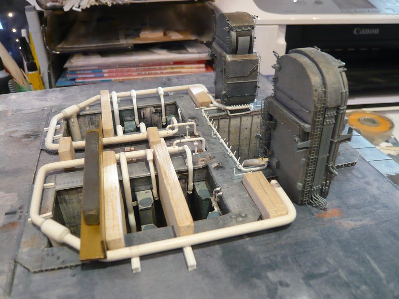
today there is only a short update from the growing pipe skeleton around the left SRB shaft. ![]()
As already announced, the ring line behind the LOX-TSM was extended by the 16’’ tapering with the subsequent transition to the 12’’ nozzle tube. Again, the precise and, above all, stable position of the ring line is important, for which purpose the line was again weighed down in a proven way with a weight. ![]()
After the alignment of the nozzle pipe under the TSM the extended pipe was glued to the end of the ring line with MEK.
And even after removal of the weight, everything was still stable.
Now only the already prepared two small 6’’ outlets still have to be glued on the ring line, which lead into the SRB chamber, then the first ring line would be complete.
That’s it for today. ![]()
![]()
6 Likes
Hello friends of the endless SSWS pipes,
this was unfortunately too briefly thought. ![]()
The two small 6’’ outlets can not yet be glued as long as I still need the space behind the TSMs for the Balsa spacers in the corners to fix the position of the ring lines, in order to also to be able to mount the outlets on the other ring line in a stable position. ![]()
At first, the rear 18’’ outlet was glued with the two support plates. However, at that I was not aware that this time I had begun on the inside, and with that on the wrong side, but what was to become apparent only later. ![]()
So it went on with the two outlets between the SRB-Supports.
The two 9’’ transitions are again only placed on and the small supports are only supported underneath.
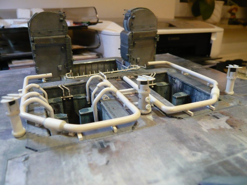
And as one can see, even after taking away the spacers and weights, everything still fits together well and looks quite well. ![]()
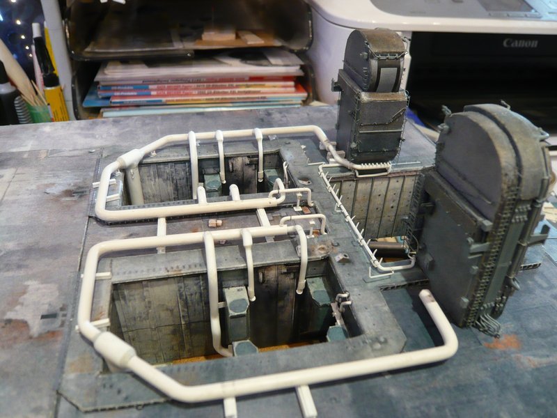
And the total view with the flock of birds also looks like cool. ![]()
But when I wanted to extract the pipe skeleton, the shocking realization came that I had begun on the wrong side. ![]() Now the skeleton was blocked inwards by the three outlets and outwards through theinlet pipe in the shaft corner.
Now the skeleton was blocked inwards by the three outlets and outwards through theinlet pipe in the shaft corner. ![]()
But with the utmost caution and the necessary sensitivity, I then managed to move the rear outlet with the support plate around the SRB support. ![]()
Now I can again carefully remove the two SRB-Supports, in order to be able to mount the three external outlets on the inserted skeleton. ![]()
![]()
5 Likes