Space Shuttle Launch Complex 39A with Challenger STS-6 (1:144)

Something to consider is the fact that those pipes were moving millions of tons of high-pressure water through them, which would have a substantial cooling effect on them. The exhaust nozzles of most liquid fueled rockets use the same principle by piping propellant through the bell to keep it cool enough that it’s not burned away in the first few seconds. This also has the benefit of heating the propellant prior to combustion, making the reaction more efficient.

:beer:

2 Likes

Hello together,

after all the outlets of the SSWS have been completed with some missing Pipe Supports could actually follow their assembly at the ring lines.

I will begin with the transitions from the now finished 36’’ inlet pipes (Ø 6,3 mm) to the two 24’’ ring lines (Ø 4,0 mm),


Source: NASA

whose connecting sleeves are finally positioned and glued to the ring lines.

Then follows the modeling of the transitions of these six 18’’ outlets (Ø 3,2 mm) with the tapers to 12’’ (Ø 2,0 mm).

And then there are still these two outlets at the end of the ring lines behind the TSMs with the tapers to 16" (Ø 2,5 mm) and then to the 12" nozzle pipes (Ø 2,0 mm).

These four rear 18" outlets (above) and the two front 12" outlets (below) have no tapers and are already ready for assembly.

When these transitions are modeled, the outlets can finally be glued onto both ring lines. And then these connecting points must also be modeled.

So, all in all, this looks like an extensive Apoxie Sculpt session at which we then will see us again.

5 Likes

Catch up time — those vids were very interesting - genius ideas and it really was an evolving program to make it more effective and safer. Its such a shame they stopped the shuttles… it feels like so much was done and now its a wasted opportunity with so little space travel now.

2 Likes

Yep John, therefore let us keep the legacy of the Shuttle program alive.

1 Like

Hello everybody,

so, now I have begun with modeling the transitions, first with the transitions on the two ring lines,


Source: NASA

which are still quite accessible and handy.

First, two equally sized marbles were formed from the two Apoxie Sculpt components,

which were then kneaded until they were completely mixed, which can be seen in the white color.

And then the transitions were modeled on the two sleeves, which can be made at the same time.

Thereby it is helpful not to take too much Apoxie Sculpt and then keep it in the mean time occasionally to moisten in order to stay flexible.

Then followed the six 18’’ outlets from the ring lines into the SRB shafts, and this action was then much more tricky and stressful.

Since these parts can hardly be held in the fingers, but they still have to turn and turn around constantly, this was absolutely no nerve balm.

Thereby one thing turned out to be particularly hindering, and these were the tiny nipples on the bows and the lower baffles, which I should have installed better afterwards.

As a result, the transitions have not worked out as good as one can see. But I wanted to make use of the time before the mass hardens too much, and so I have stayed the course.

But now I leave all this dry and then I will rework the transitions separately by sanding.

That’s it for today.

6 Likes

Hello everybody,

well, seen in hindsight, I have applied a bit too much Apoxie Sculpt (AS) and now have to sand off something, but this is easy to do because the AS is very dense and extremely fine-grained after the hardening.

But this effort would have been significantly reduced if I had already formed the transition better in the damp state and adapted it to the rather concave shape. But afterwards one is always wiser.

Therefore I have to shape this concave transition with different files, sanding sticks and finally with 2000er sanding sponge, which is already a bit arduous, but what the heck!

Here already a first picture of one of the transitions, on the left the somewhat chubby modeled form, and on the right the post-processed form, which looks optically already quite well.

In fact, the transition could be even something shorter if I exactly look at the picture once again.


Source: NASA

At the transition on the second ring line (above) I was then already somewhat more relaxed, since I knew that there was something significantly to sand off,

as can be seen here at the right transition.

And these are the finished transitions.

And now followed the transitions at the six 18’‘-12’’ outlets, which also have a slightly concave shape.


Source: NASA

Although there is less material to remove, but their handling is more tricky due to the small size. For comparison, I have put a raw state next to it.

And tomorrow the remaining five outlets will be reworked.

7 Likes

Some serious work you’re putting into this build. This is going to be spectacular once you’re all finished!

Thanks for looking in on here,

I hope so too, although there is still a long way to go.

1 Like

Hi guys,

as I have already indicated, I have now after all brought myself to shorten the transitions at the 36’’ outlets of the ring lines, and I imagine that they fit better now into the overall picture.

And these are the 18’‘/12’’ outlets with the reworked transitions,

And here are finally the finished transitions at the 16’‘/12’’ outlets to the both nozzle tubes.

And as next step, the final assembly of all the outlets on the two ring lines begins then with the mounting of the inlet pipes.


Source: NASA

8 Likes

lovely clean work Manfred.

Wow Manfred, totally awesome as usual. I was reading along then seeing those videos of how NASA solved the noise problems was genius. What is interesting…quickly made me think about your change of text because I saw this on my iPhone screen…

I was thinking what the heck…hello together…on a scooter?? then I realized it’s an advertisement in the middle of your post. :rofl:

1 Like

Thanks Mike for looking in on me again,

this is learning by doing!

BTW, it looks like your iPhone needs a system update, brother.

Hello together,

before the assembly of the inlet pipes, however still had to be determined their exact length, so that they fit exactly into the corners of the two SRB shafts and end with the coupling sockets at the MLP bottom.

For this purpose, the tubes at the upper end must be shortened. At this place, the half-round recesses have to be sanded, whereby the special position of the coupling stubs in the pallets must be observed. And that looks exactly that the (still missing) pipe support sits over one of the three 120° staggered locking points (the rectangular rib pairs) on the inner SRB wall, as can be seen here a bit more distinctly.


Source: NASA

And as I wanted to be sure during shortening of the inlet pipes were shortened, I used a somewhat longer dummy and sanded the necessary recesses at the end.

Then I have sticked this dummy with some Pattex under the outlet of the ring line and in this way could mark both the end point of the pipe at the MLP bottom and the corresponding position of the recess at the connection point.

And to this length, the supply pipes could now be shortened with a quiet conscience, and then also the recesses could be sanded at the right place.

And that looks so,

and the same length should have the outlets also, therefore the interim examination at the end stop.

And the adjustment at the connection points also looks good.

So, this should have been for today, and tomorrow the inlet pipes are then mounted on the ring lines.

7 Likes

Same level of skill and artistry as always. Lovely work

Thanks John, it’s great if you still like it what I’m doing here.

1 Like

Hello everybody,

meanwhile the assembly of the inlet pipes has gone over the stage, whose result I would like to introduce you briefly.

The positioning and simultaneous bonding of the pipes under the ring line was somewhat tricky, but finally has worked quite well.

Important was the vertical alignment of the pipes in the shaft corner, for which the ring line was weighted, in order to avoid slipping.

Now the bondings have only still to dry through,

then these transitions can also be modeled with Apoxie Sculpt.

And then the supports can also be adapted to the coupling connectors.

That’s it again for today.

5 Likes

Hello everybody,

now to the supports on the inlet pipes. As they look, I know now, so I could start after the determination of the dimensions of the individual parts with the implementation. However beforehand the dimensions must be checked as always.

In the meantime, the pipes firmly adhere to the pipe lines that one has relatively stable conditions for testing their fitting.

At first I have cut two small sickles out of the remains of the cut-out 8 mm discs,

which now have to be glued to the two rings above the locking plates on the outer wall of the shaft, the question is only how to do this without slipping?

Holding the tiny sickle to the ring with the tweezers is relatively difficult, especially since the line-shaped gluing site would be probably rather unstable.

On the other hand, a middle strip (1 mm x 1,8 mm) would be very helpful,

because it would serve as a stop at the same time.

Here the part is already glued,

so that now the upper sickle could follow. And now only the small base plate is needed for attachment to the shaft wall,

which can be seen here,


Source: NASA

Now the first support is finished,

and also the test at the shaft wall looks quite good.

And tomorrow follows the support on the other inlet pipe.

5 Likes

Once you’ve painted/weathered all this fantastic plumbing I’m fairly sure it will be near-impossible to tell which is the real thing and which is your layout. Amazing work.

2 Likes

Thanks Tim for your compliment,

I’ll keep trying to give my best, and then we’ll see.

Hello everybody,

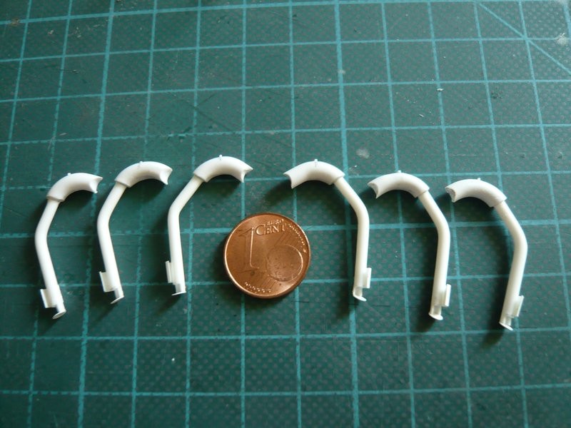
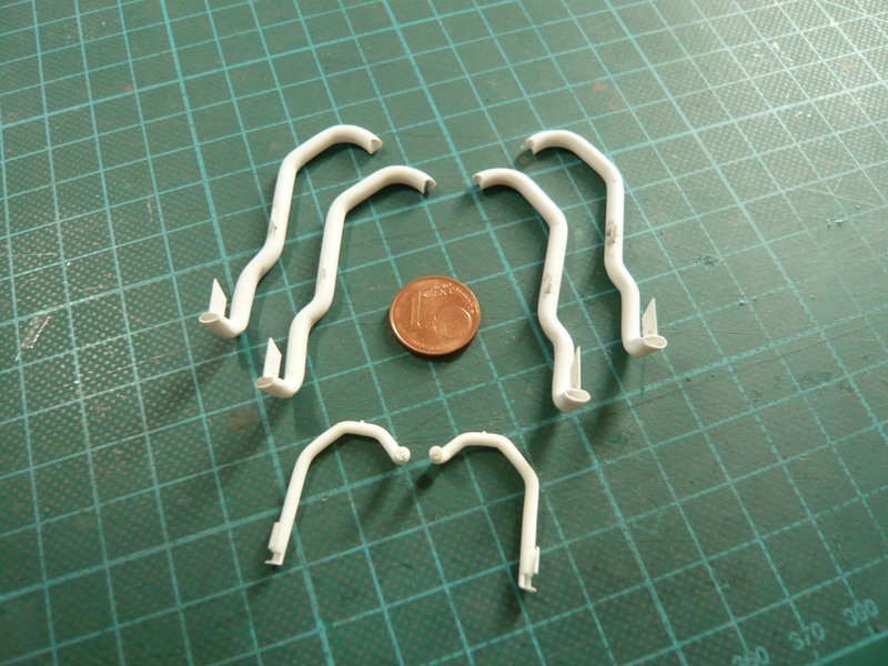
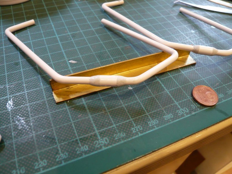
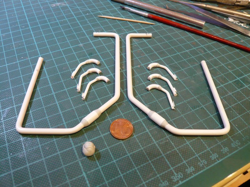
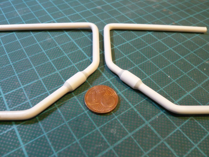
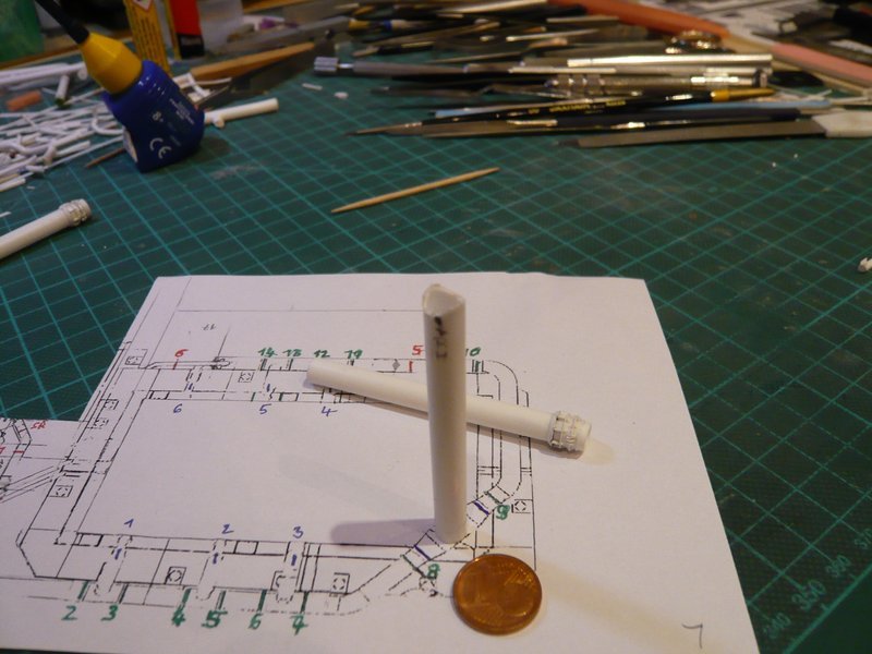
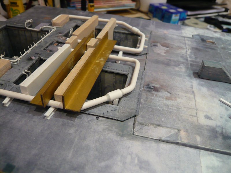
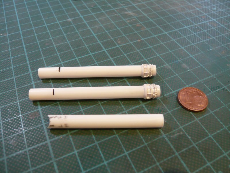
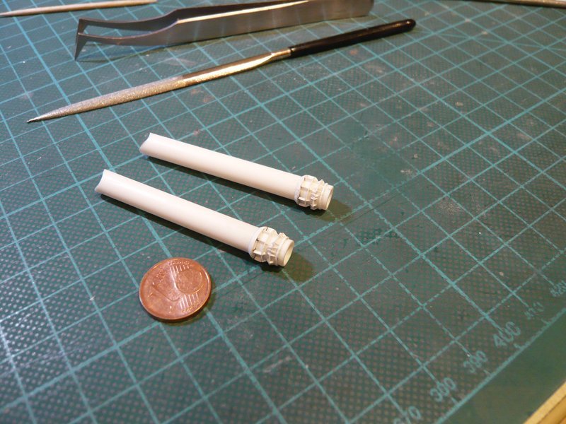
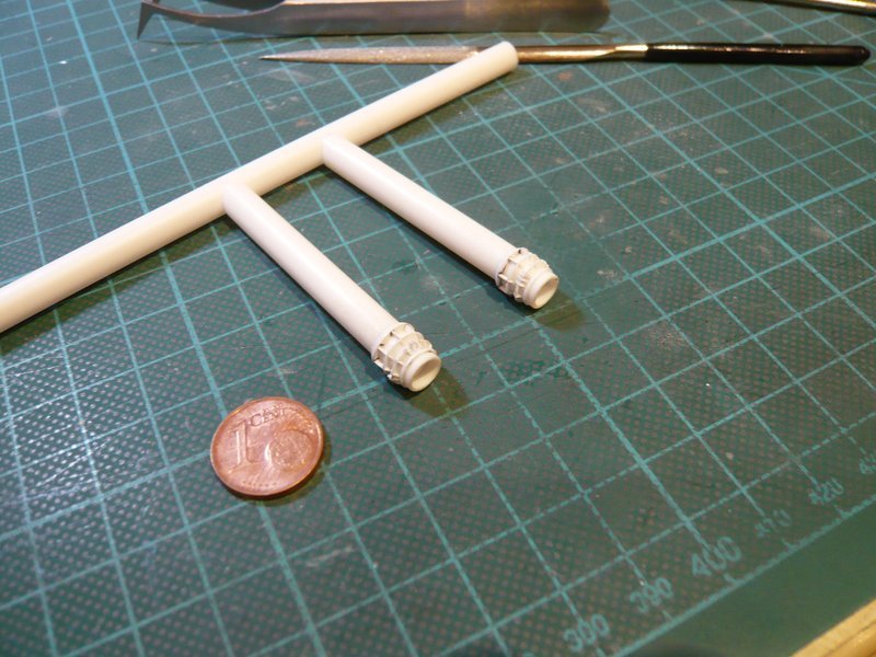
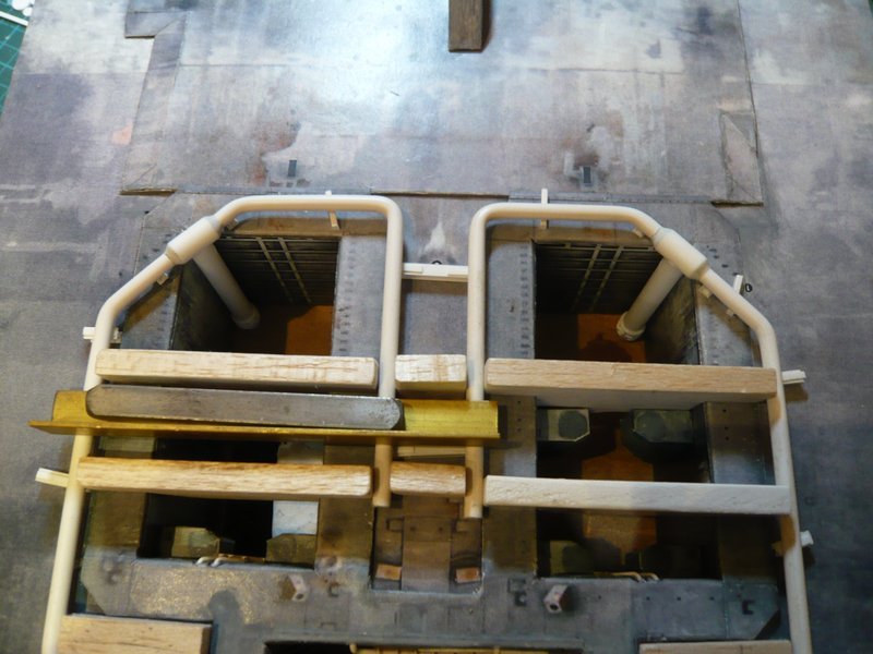
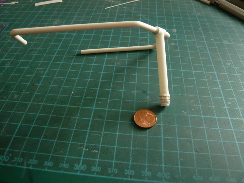
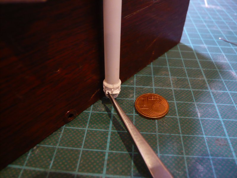
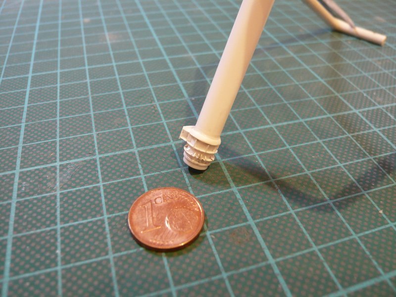
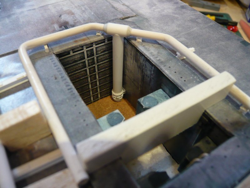
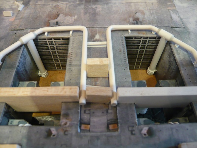
meanwhile also the second inlet pipe has got its support,

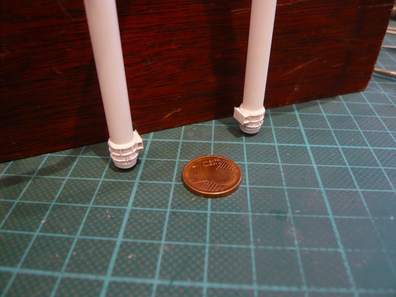
and both pipes fit well at the walls in the chamber corners.

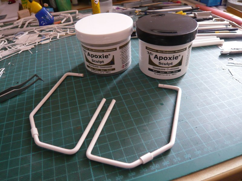
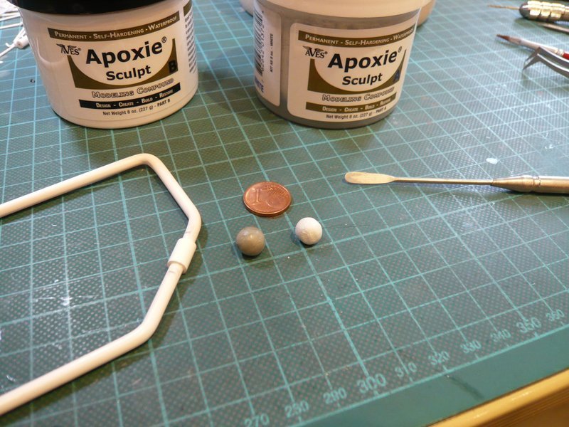
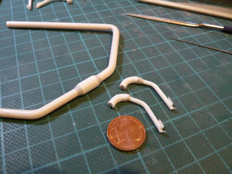
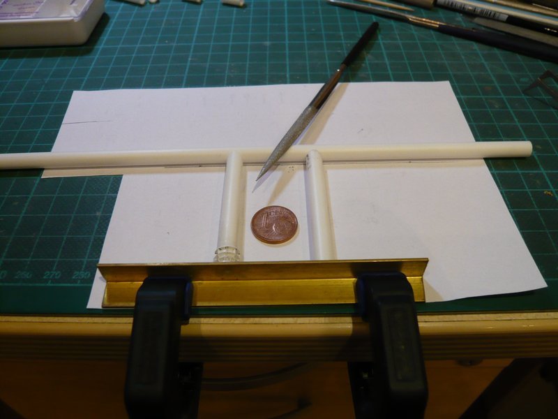
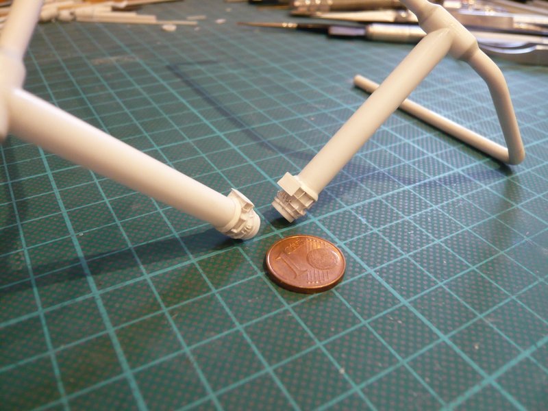
Next followed the modeling of the transitions from the tubes to the ring lines, as usual again with Apoxie Sculpt.

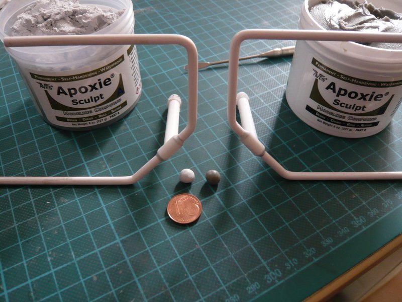
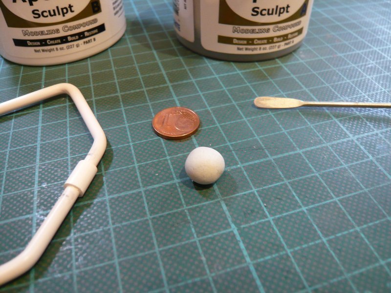
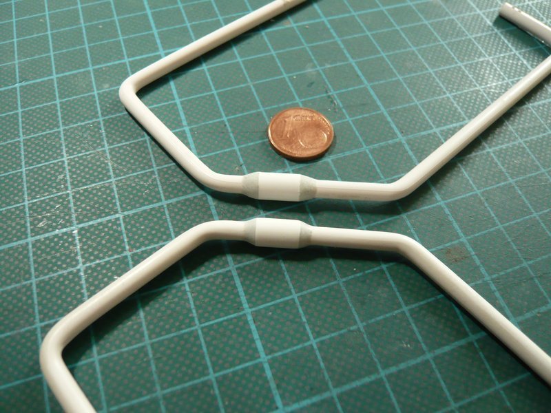
After thorough mixing of the two components, the mass was rolled into two thin rolls and modeled around the transitions. And as you can see at the rest of the pellet, I had misjudged it again, since the half would have been enough.

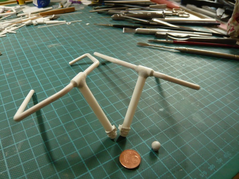
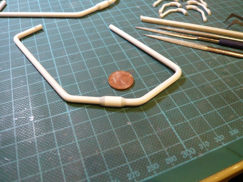
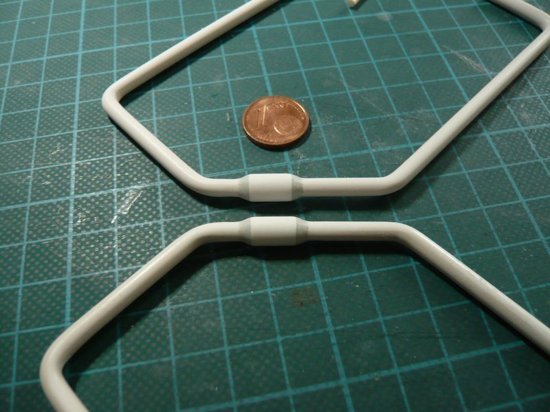
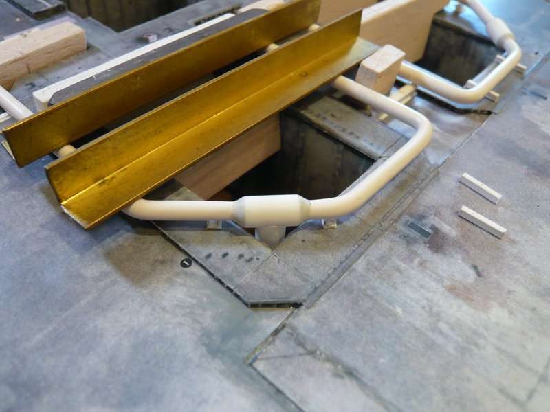
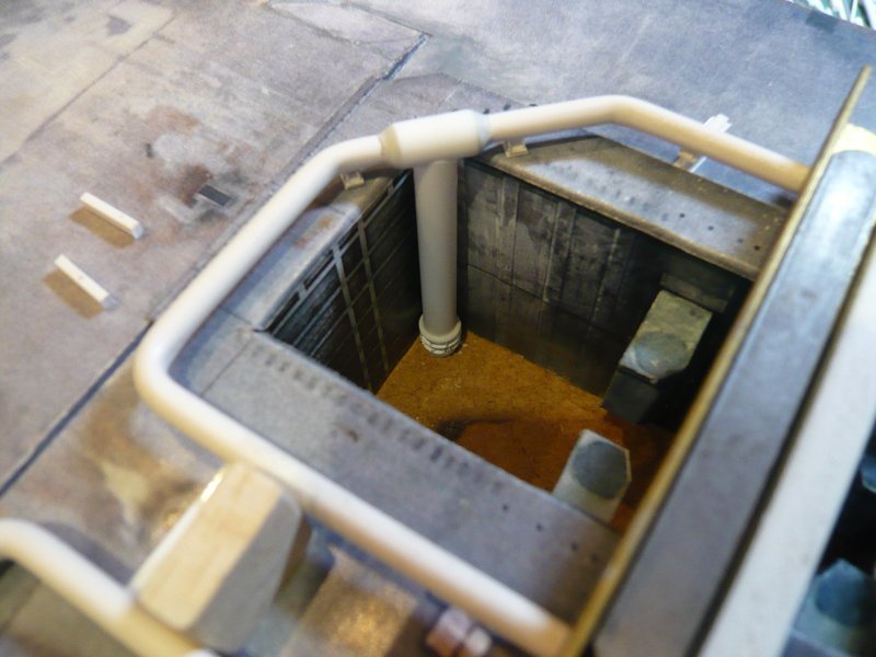
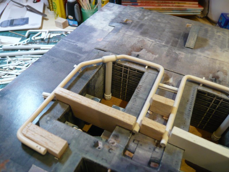
Now I have to wait until the mass has hardened, in order to be able to shape the final contours of the transition, but there is something to be sanded off again.

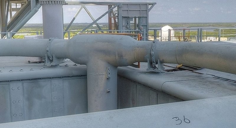
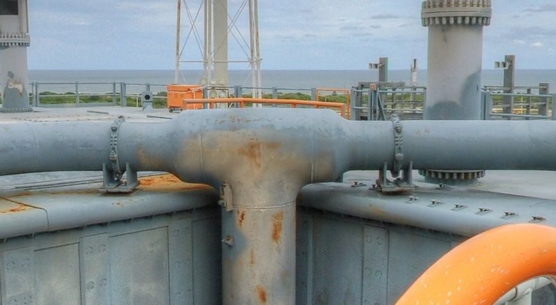
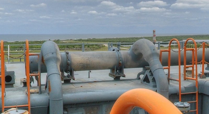
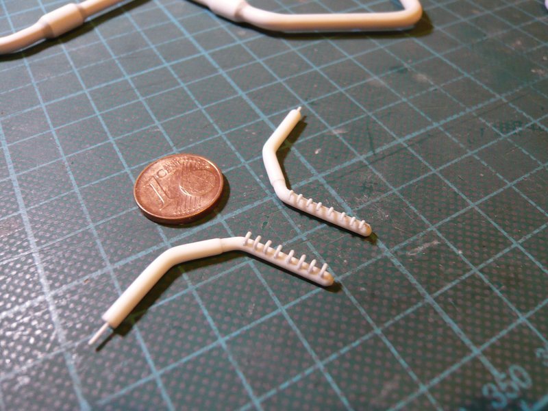
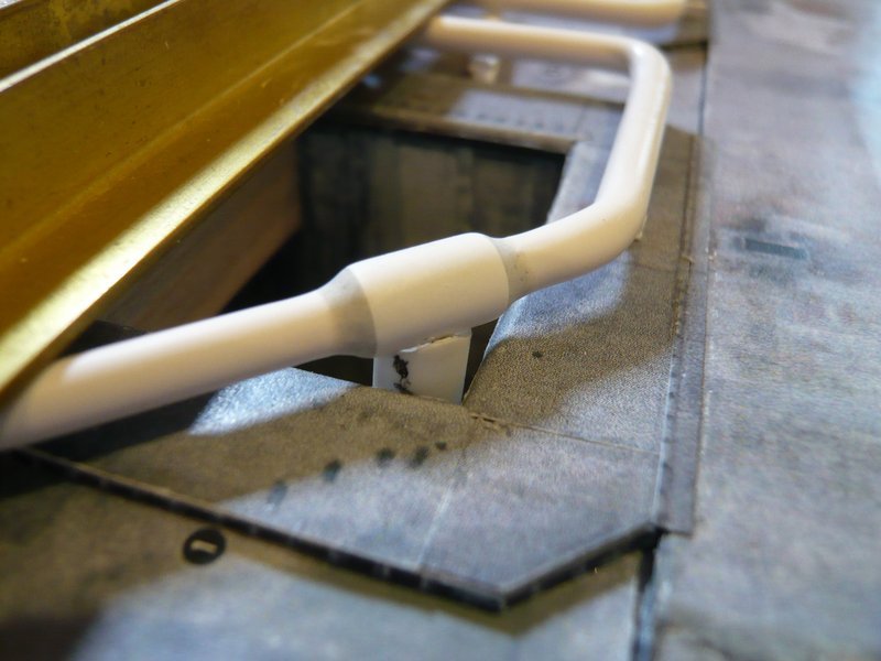
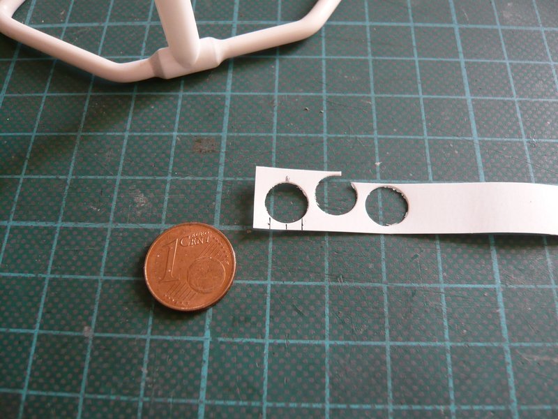
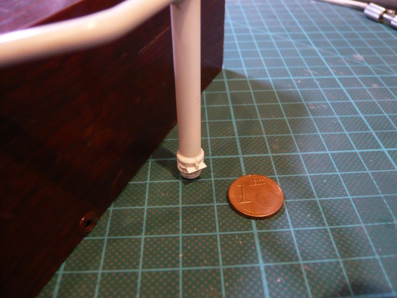
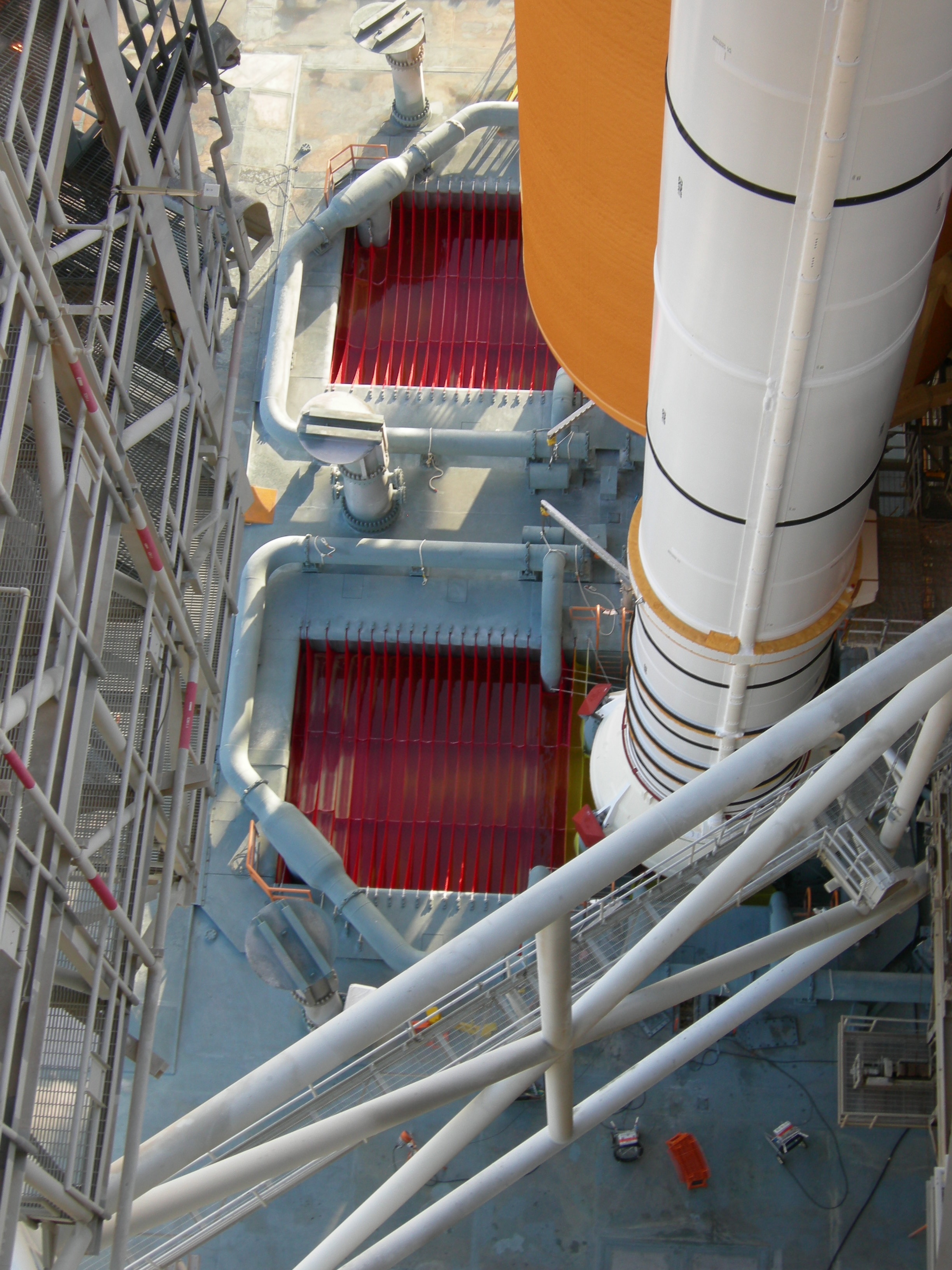
And now to these two small details, which I at first did not pay much attention. But now I’ve figured out wherefore these parts are mounted there.
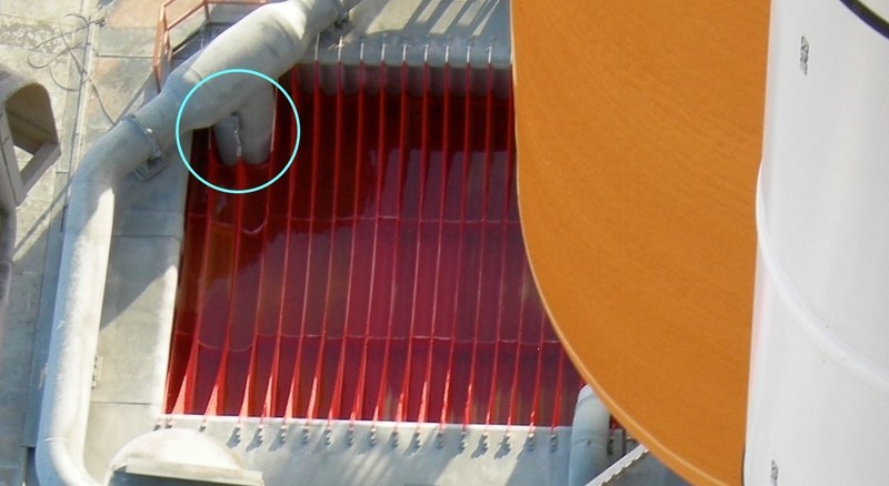

Source: NASA

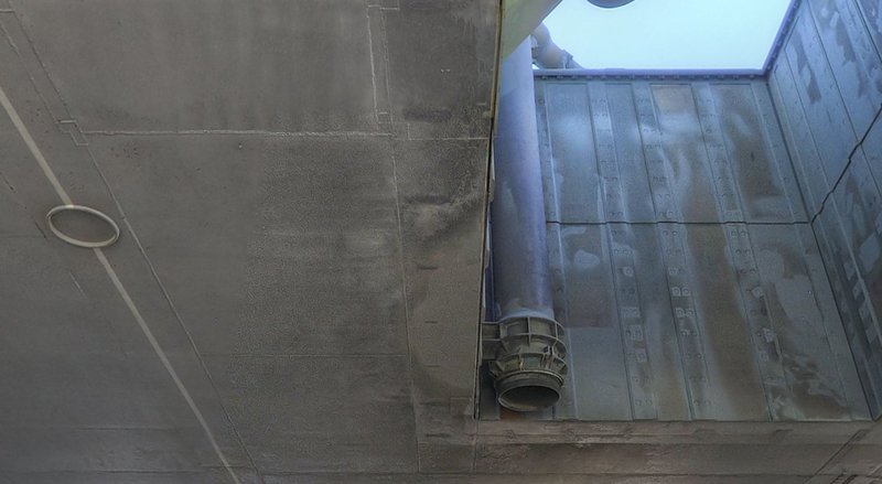
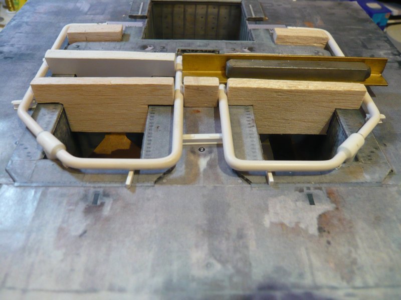
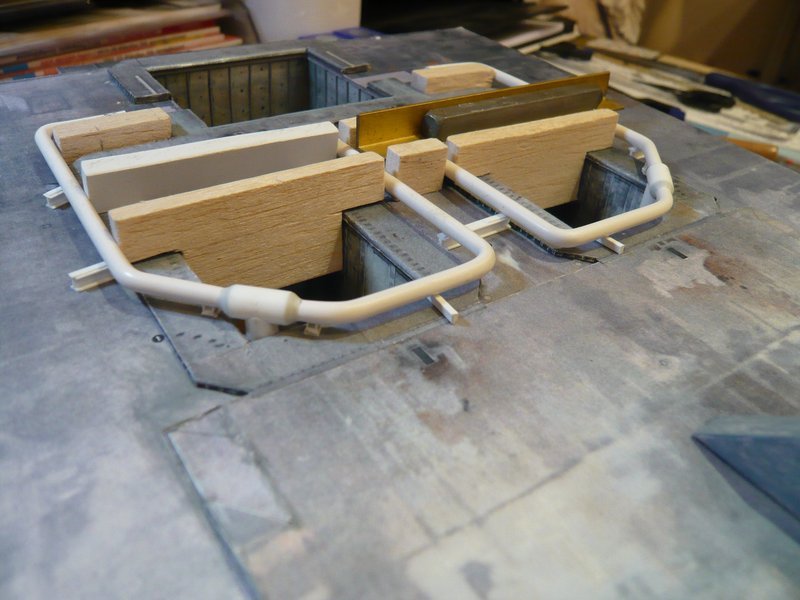
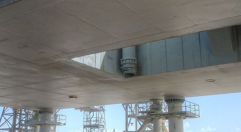
These are brackets specifically for the carrying ropes of the two Water bags, which are attached behind the inlet pipe.
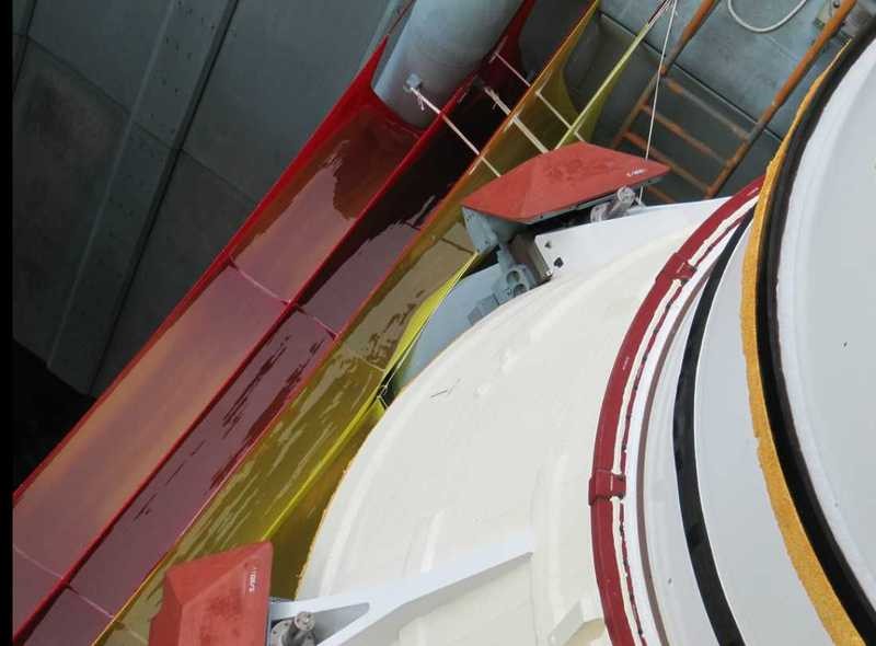

Source: flickr.com

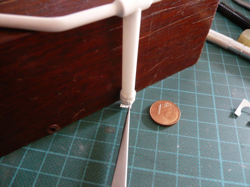
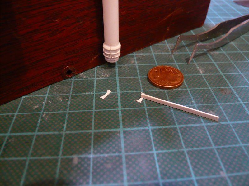
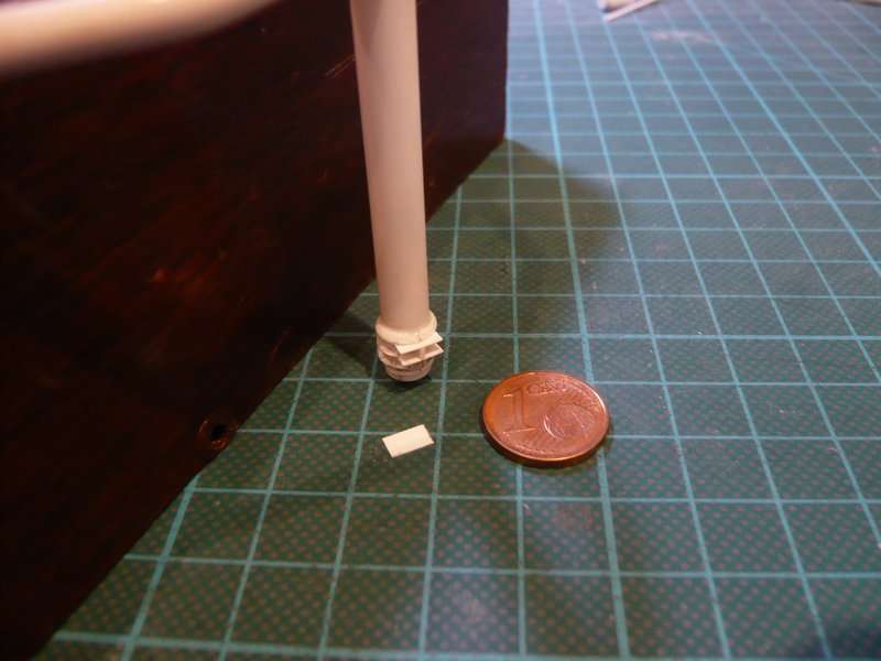
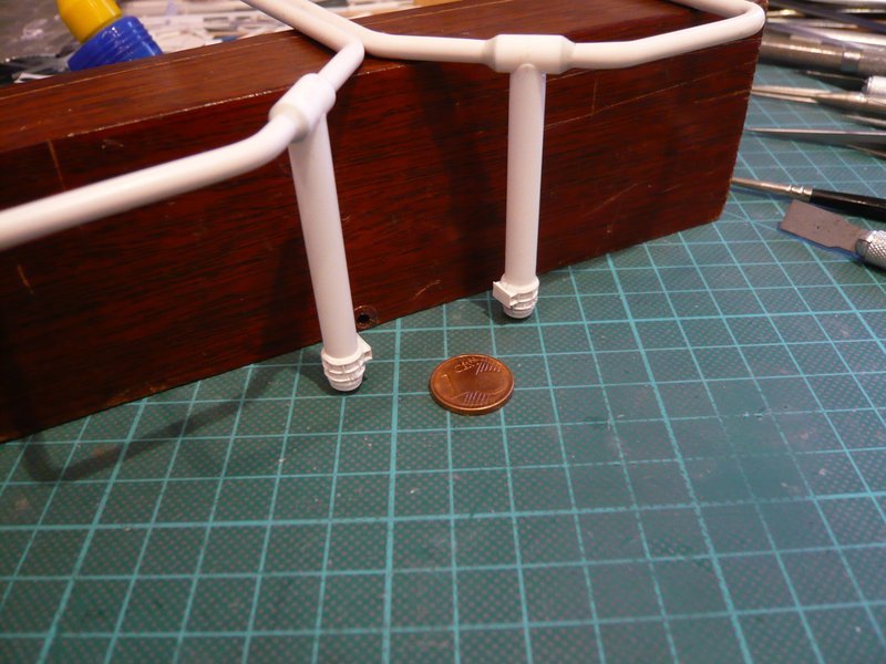
The retaining strip is only a small strip (0,8 mm x 0,8 mm x 2 mm) and the deflection pulley even more tiny, but I simply want to try, whether it can still be scratched.

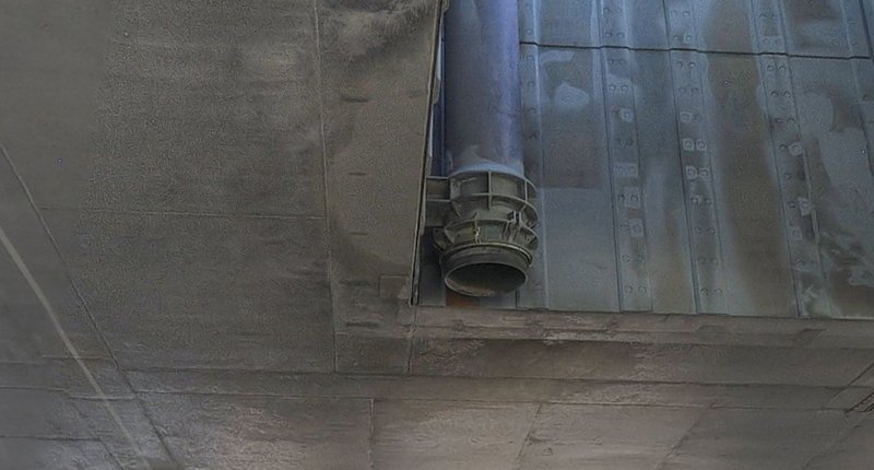
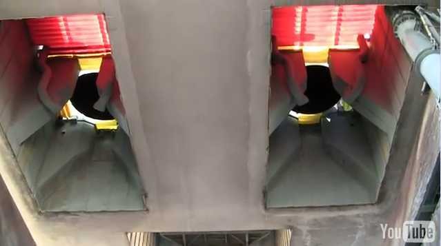
The Water bags are plastic bags filled with water, which were hung in the two SRB Exhaust chambers and were also to absorb the pressure wave from the booster ignition and prevent the reflection of pressure and sound waves.

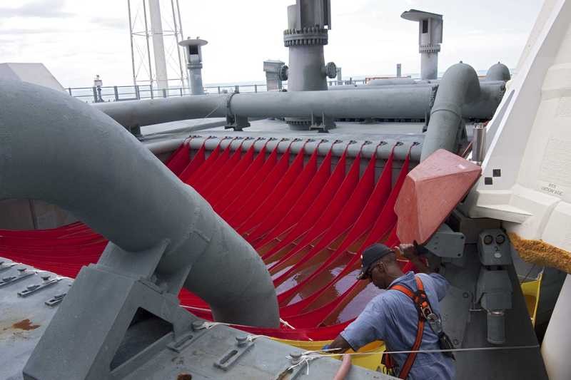
This so-called SRB Ignition Over-pressure Suppression System is a subsystem of the SSWS, which due to damage to the Columbia during launch was retrofitted after the first Shuttle mission STS-1, as was the ring line system with the outlet pipes. The STS-1 initially only had the six Rainbirds, we had discussed about, as you can remember.

Here are some more interesting images.


Source: NASA


Source: NASA

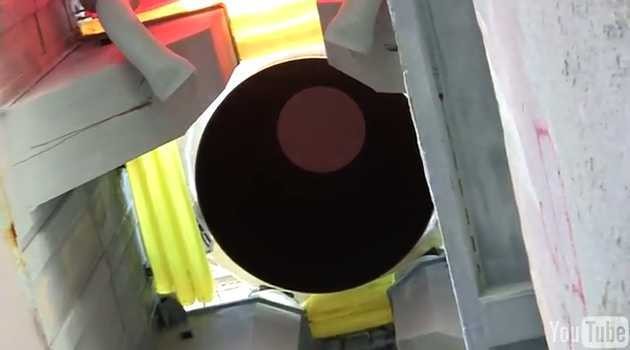
And here from a YouTube video from the perspective below the MLP.

I will come back to these Water bags in the foreseeable future.

5 Likes