Thanks John, and take comfort, my eyes are in a similar situation. ![]()
![]()
Thanks John, and take comfort, my eyes are in a similar situation. ![]()
![]()
Lower longer locking lever-lower longer locking lever-lower longer locking lever-lower longer locking lever-lower longer locking lever.
Forget about saying it five times fast, I have trouble typing it five times. ![]()
Apparently not only a tongue twister, but also a key breaker? ![]()
Hello everybody,
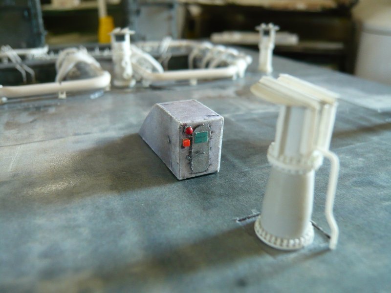
and so on with the equipment of the Stair Housing with some accessories, which has now also got a new door with a from red to green foldable warning sign, ![]() of which I have unfortunately shot no close-up.
of which I have unfortunately shot no close-up. ![]()
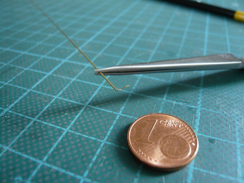
The two locking levers I have bent once more using 0.2 mm brass wire, which are in a brass tube (Ø 0,3 mm), here the longer lower lever,
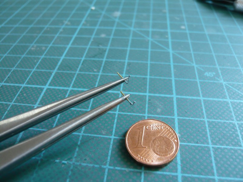
and here together with the smaller upper lever, both with a small glue ball.
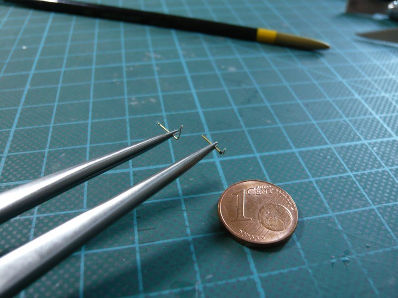
After both levers were painted gray,
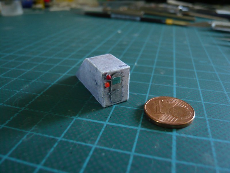
they could also be installed, and the red warning bell and the small box underneath are already attached, wherewith the Stair Housing is finished and looks good so far. ![]()
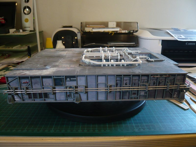
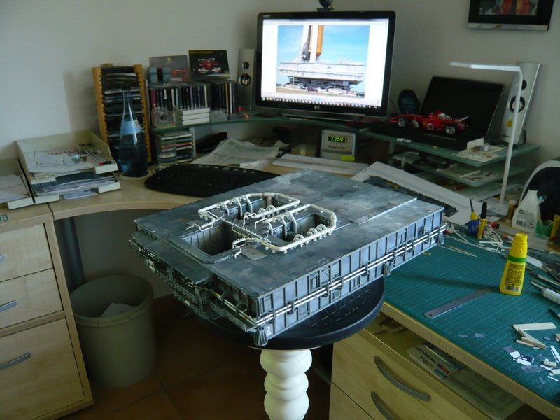
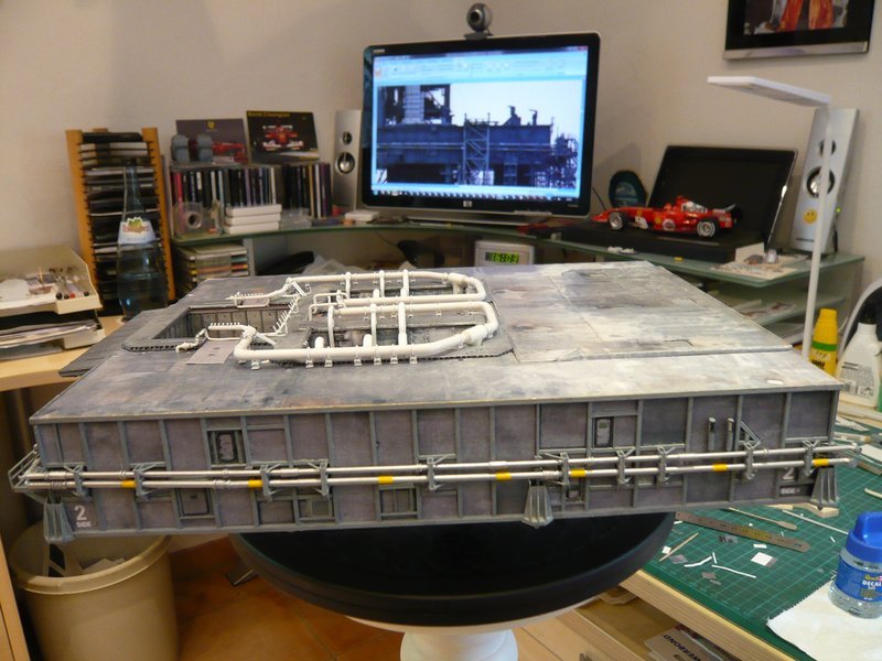
And here are some pictures with the housing on the MLP top deck. ![]()
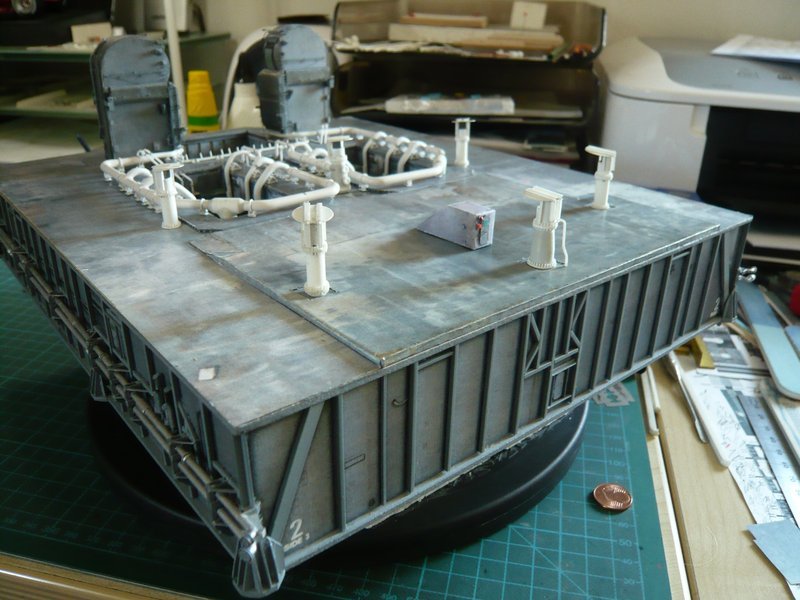
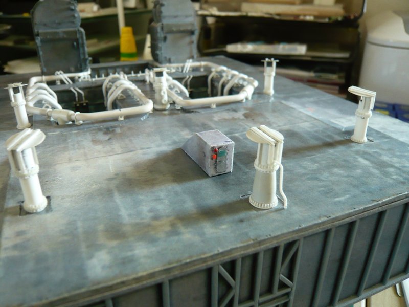
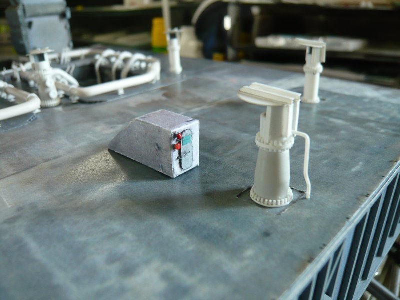
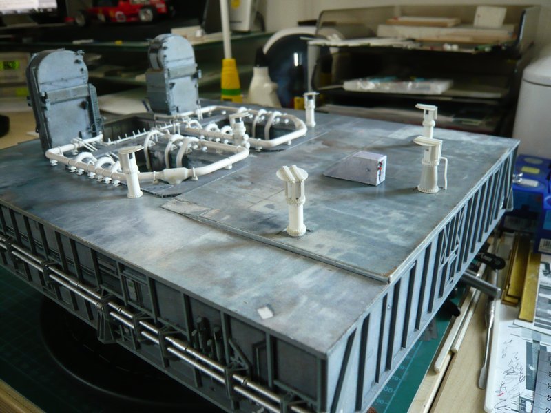
Again only a small step, but at least a nice-looking detail. ![]()
Yeah, now one can hear the bell ringing … 
But as long as the warning sign is turned to green, nothing can happen … ![]()
![]()
Hello everybody,
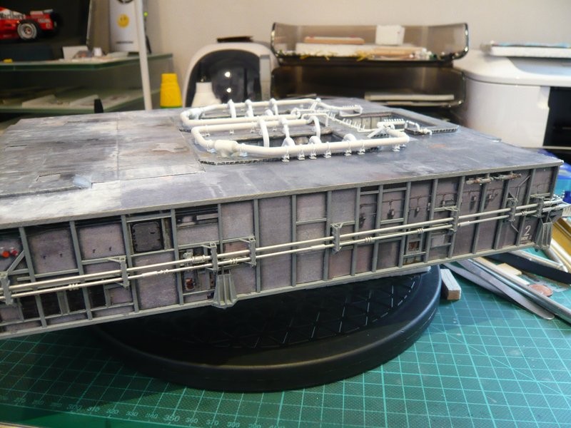
since now only are missing the cameras, as well as the railings and gutters, etc., which still can wait, I now want to take a closer look at the side walls, because there are also some nice details that should not be missing. ![]()
Let’s look at the Side 2, where there are some inconsistencies in David Maier’s Paper Kit touching his CAD Design, that contains some details that do not fit to MLP-2 and therefore need to be corrected. ![]()
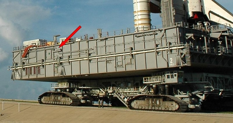
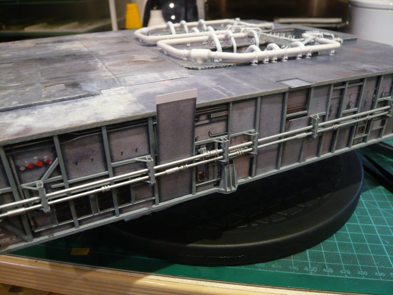
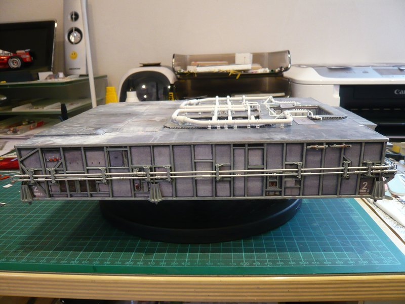
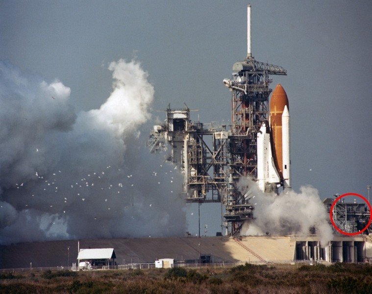
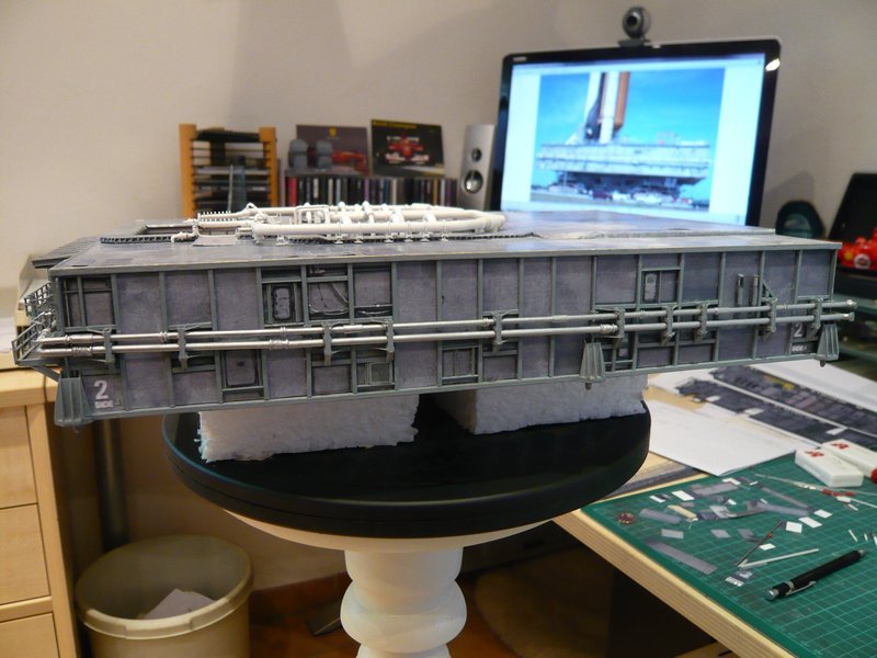
Here first this image of the Side 2 of my MLP. This side is admittedly numbered in the first and last Bay with Nr. 2 for MLP-2, which, on closer inspection, contradicts some details of the original.
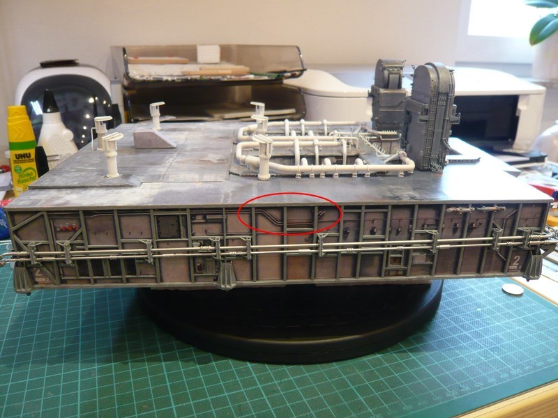
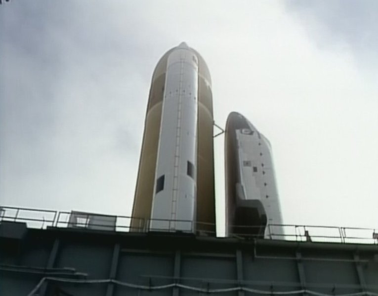
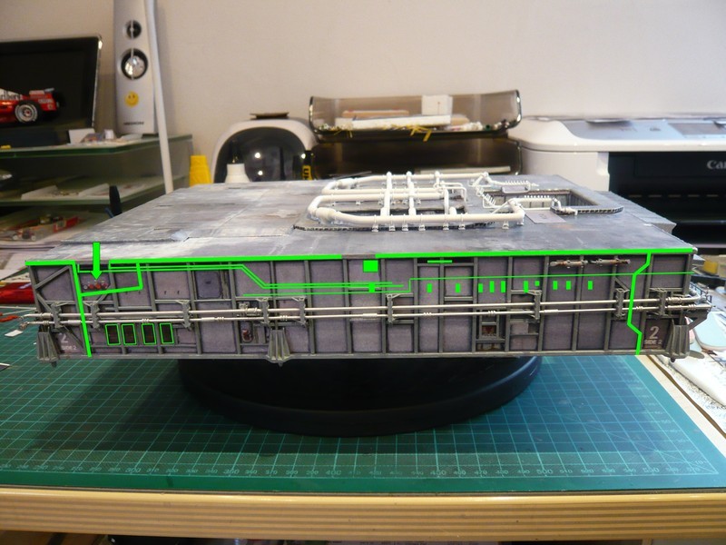
This red-rimmed three-fold kink of the two thin pipes above the LOX lines there is only on the MLP-1, which can be seen in the following pic. Therefore, David Maier obviously must have confused the MLP numbers, whyever, because otherwise I can not explain.
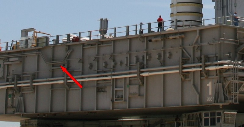
Source: NASASpaceFlight.com (NasaPhotographer, STS-116)
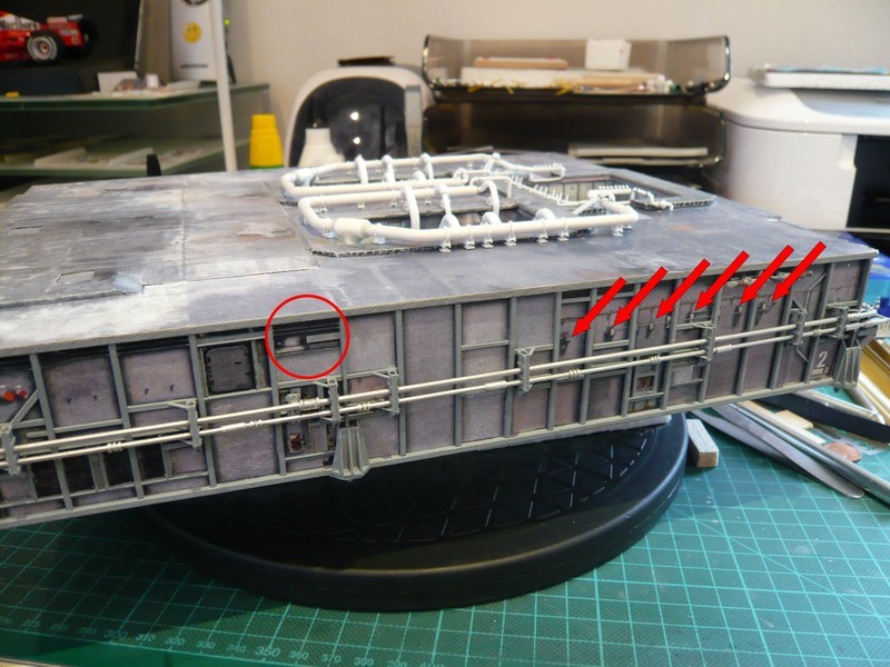
This typical route of the two pipes in the middle does not match the MLP-2, as can be seen in the next picture. Both on MLP-2 and MLP-3, these two pipes have only a double kink, which is not in the side center, but further to the left in the Bay 13, whereas the three-fold kink on the MLP-1 is clearly to the right of this interface (Bay 9-11). ![]()
David Maier also has some reference photos in his Paper Kit documentation. The curiosity about the thing is that the only reference photo of the Side 2 comes from the MLP-3, whereby the double kink here is unfortunately hidden by the service platform.
Therefore it would have been better, if the master had used the MLP-3 as a template, especially since his LC39-Paper Kit is based on the STS-135, on which MLP-3 was used. Then his CAD design would have been self-consistent and Launch Pad and MLP would get well together. ![]()
But be that as it may, one only needs to know and take into account for the construction, ![]()
which is why I simply let this false triple kink disappear and will mount these two pipes with the double kink in the right place. ![]()
Fortunately, I have made some copies of the side walls, and there are also some sheets with backup parts in the Paper kit, among others also with neutral gray bays, as one can see here, which I have used.
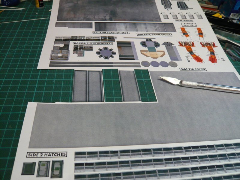
Since some bays on the side because of the slight reddish color anyhow were not to my liking, ![]() these parts for the [color=blue]Bay Lifting[/color] come just right, since they fit quite well from the color to the remaining side.
these parts for the [color=blue]Bay Lifting[/color] come just right, since they fit quite well from the color to the remaining side. ![]()
Now I have to cut off only suitable parts for the corresponding bays and thereby to redecorate, with which I have already begun here.
And so I’m hopeful that I can give this side with a better outfit. ![]()
![]()
Hello everybody,
after a little art break, it can now go on now, but therefor a little more detailed. ![]()
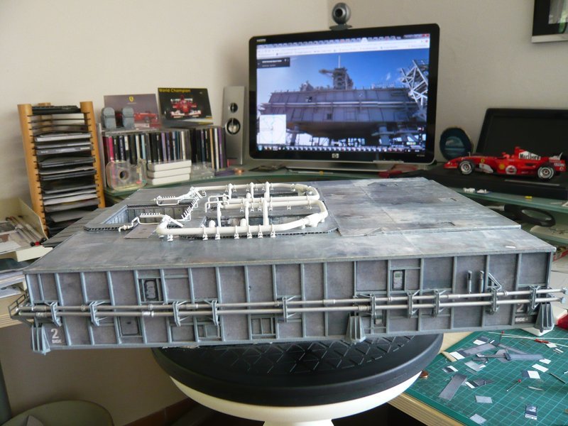
Here is an image of the Side 2 after the recent modification of some bays with some “new wallpapers”. ![]()
Now the disturbing triple kink is eliminated, but as it has turned out, it is not done with it, because on closer inspection, I have also noticed other things that are exactly related to this triple kink and finally explain its strange constructive execution, which is completely mystery to me. ![]()
The reason for my research was initially the fact that the Side 2 still did not really please me, especially since the two thinner pipes and this little red circled box on the frame in the Bay 13 seem sit too high. ![]()
Moreover the marked supports on the right (Bay 3-8) have too big shadows, and as I wanted to scratch the supports anyway, they should then cast their own shadows. ![]()
That’s why I did still some ancestral research and have looked at my few old reference pictures from the [Side 2() at times of the STS-6 and afterwards, but they don’t show enough details because they are simply too fuzzy. And the awesome HiRes NASA or Street View panoramas from the past few years unfortunately do not help, but only clarify the dilemma with which I must necessarily live with during my Real Space Scratching of my models. ![]()
Meanwhile, I’m a bit smarter and I know that I can also redecorate this box on the frame in the Bay 13, as there was no such equipment at the MLPs during the first shuttle years, but instead a different typical detail on another place. ![]()
A first clue for this was the shot from Challenger’s Rollout for the STS-8 (1983), which at first glance seems less exhilarating, because one can hardly see any details on the Side 2. ![]()
Therefore, I would like to draw your attention directly to this encircled hutch, which later inter alia can explain the position and shape of the triple kink on Side 2 of the Paper Kit.
In the linked HiRes resolution one can see this somewhat larger box in the Bay 10 more clearly, and the practiced eye can also recognize the double kink of the two pipes on the left even though only hazy.
And here is a shot of the STS-6 from this NSF forum by Ares67, which shows on the left side of the picture that this box above the two thinner pipes at that time already had existed, actually logical, since both missions are only a few months apart. ![]()
Source: NASASpaceFlight.com (Ares67)
In the course of these findings, I have recollected to images from the Side 4, on which I had noticed a similar box, which can be seen in the following image section from the Lift-off to the STS-6 and that it has oblique supports.
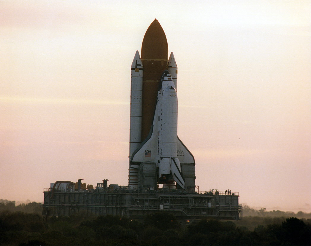
After my overview so far, there were these boxes at the MLPs at least until the end of the 80s, as one can see on this picture from the rollout of the Discovery on the MLP-2 for the STS-29 (1989). ![]()
Since these middle boxes are not available in the Bay 10 in the paper kit, I can now adjust myself to this and can omit these other boxes in the Bay 13 and the triple kink of the pipes (Bay 9-11) with clear conscience. ![]()
But now still to the elucidation of the location of this triple-kink in the paper kit, which is indeed on the Side 2 of the MLP-1. The reason for this becomes clear very quickly from this image of the Rollout of the Columbia to the STS-1, although I had to evaluate lots of images. But from the STS-1, there are luckily most of the images you can find in the KSC-Media-Archiv.
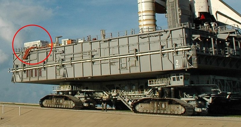
As can be seen in this picture, earlier this box was sitting there, around which the pipes were installed. I suspect that it could be a kind of Firex water tank, because you can see a red pipe on the right, which would speak for it. ![]()
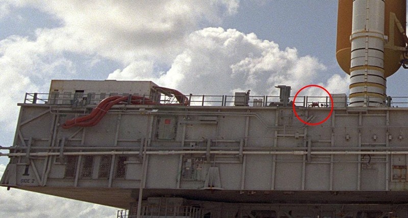
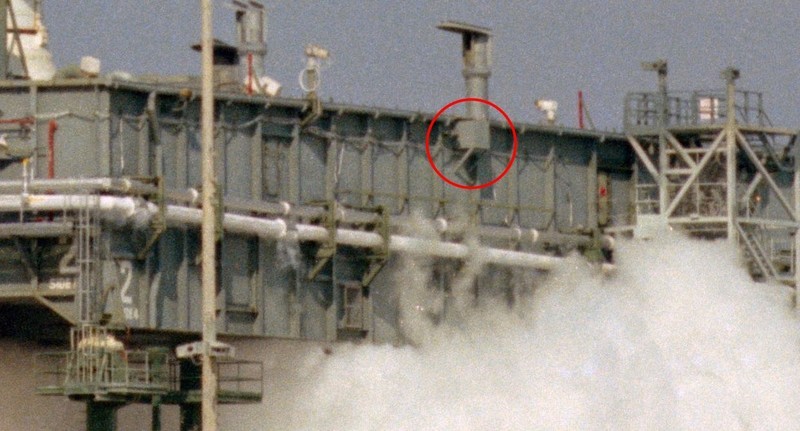
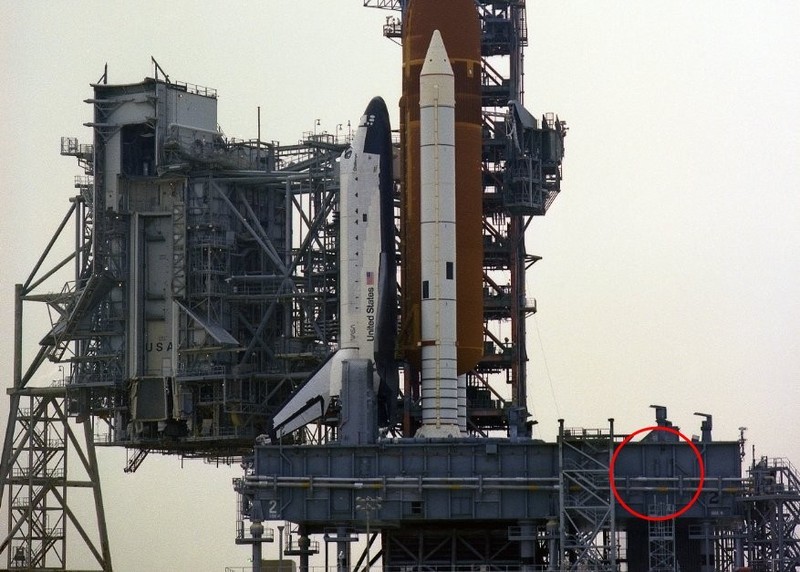
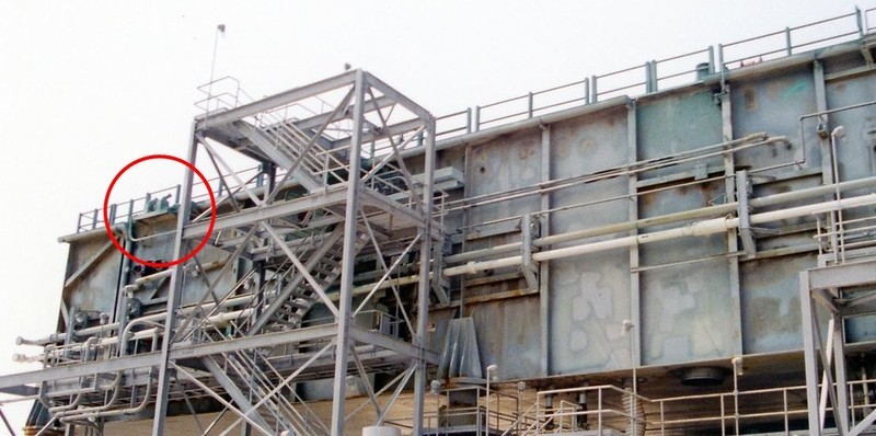
These boxes were later dismantled on the MLP-1 (red circle), as can be seen in the image of the STS-79 (1996). And since then there is in the Bay 13 instead this box on the frame (green circle), which is existing in the paper kit on both sides, but for the MLP-2 they are absolutely wrong there. ![]()
For the sake of completeness, it should be mentioned that the old boxes on the MLP-2 were also sometime dismanteled and replaced by the boxes on the frame, as shown in this picture of the STS-115 (2006), which was then also freshly painted.
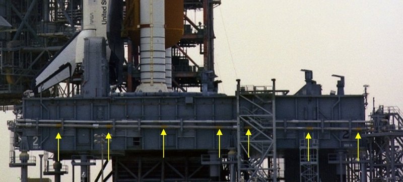
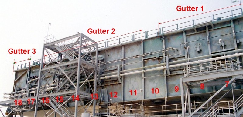
And now I come to the great photos of the MLP-2 from John Duncan from the year 1998, which I actually wanted to use as standard reference photos for the further detailing of the side walls. ![]()
Since it is soon time to deal with the "roof"gutters, which are interrupted several times, I have numbered the Bays on the Side 2 for better orientation, since I do not always want to count them again for myself. ![]()
I can still use these images well for scratching, since one can see the details of the pipes and the supports very beautifully.

Source: apollosaturn.com (John Duncan)
Source: apollosaturn.com (John Duncan)
I just have to keep in mind that I have to omit the box with frame in Bay 13 and mount the old box in the Bay 10. ![]()
And finally there are still some small things that I need to correct on this occasion on the Paper Kit side walls, of which more later.
After seeing things a bit clearer and having penetrated through David Maier’s MLP confusion, I feel immediately more comfortable again. ![]()
![]()
Nice update with yet more super detailing. Always great to catch up with this ![]()
Thanks John for looking in on me again. ![]()
![]()
Hello folks,
I want only briefly tell you that I had a good nose with my guess regarding thi box. ![]()
As I have discovered in an isometric representation of the MLP-1, Fire Hose Reels were in these boxes. ![]()
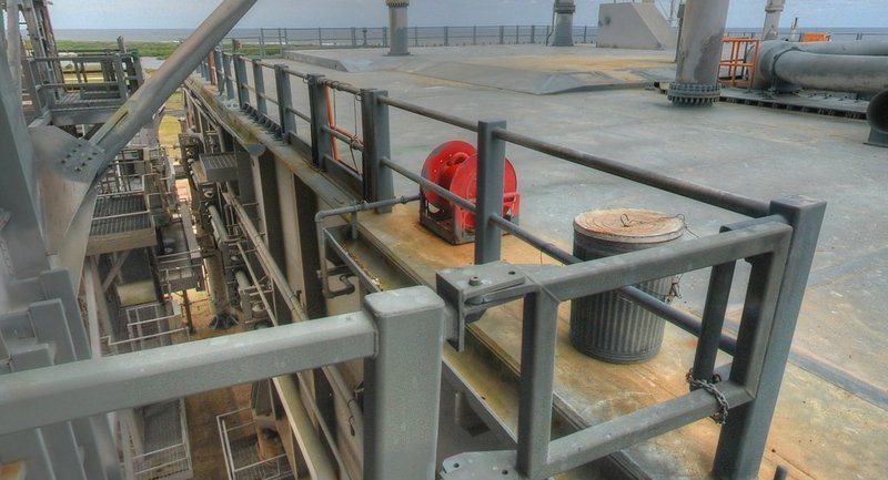
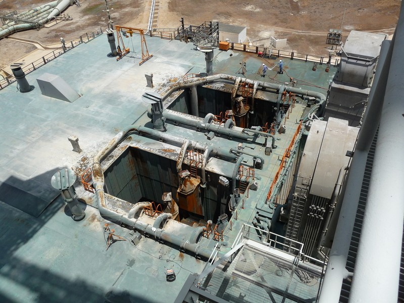
After dismanteling the old boxes, these hose reels were then mounted directly on the top deck, which were connected by a thin tube coming from the side wall (Bay 10), as can be seen in this image.
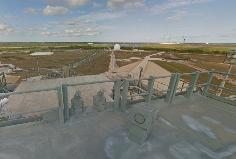
And here is a pic from the matching panoramic shot of the later MLP-2. ![]()
Before it goes on with the side walls, here still an appropriate image of the washing and cleaning crew during the Pad Washdown with the long hose from the hose reel to remove the traces after an ordinary start. ![]()
Source: NASASpaceFlight.com Forum (padrat)
But this was always routine work for the pad guys. ![]()
![]()
Hello everybody,
it went on with the Side 2, here is an intermediate step with the redecorated left half, ![]()
and here the somewhat harmonized and now almost “new” side, which I like much better now. ![]()
And on this picture the details can be seen, which are now/again to be attached.
These are beside the box, the pipes and supports, the three rain gutters with downspouts, whereby the angled, oblique tube at the end of the side (Bay 16-17) is not present in the paper kit. This is due to the wrong MLP-1 version of David Maier, which I will not go into, where this downspout does not exist.
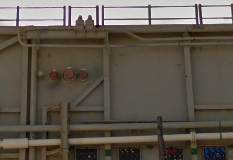
On the Side 2 of the MLP-2, there was this downspout from the beginning, how also in the STS-115 can be seen in the next image.
In the Bay 17 are still the red ports for the purge lines of the Orbiter’s Environmental Control System (ECS), on which the thick red hoses of the Mobile Portable Purge Unit (MPPU) are connected, which should be placed there as a connector.
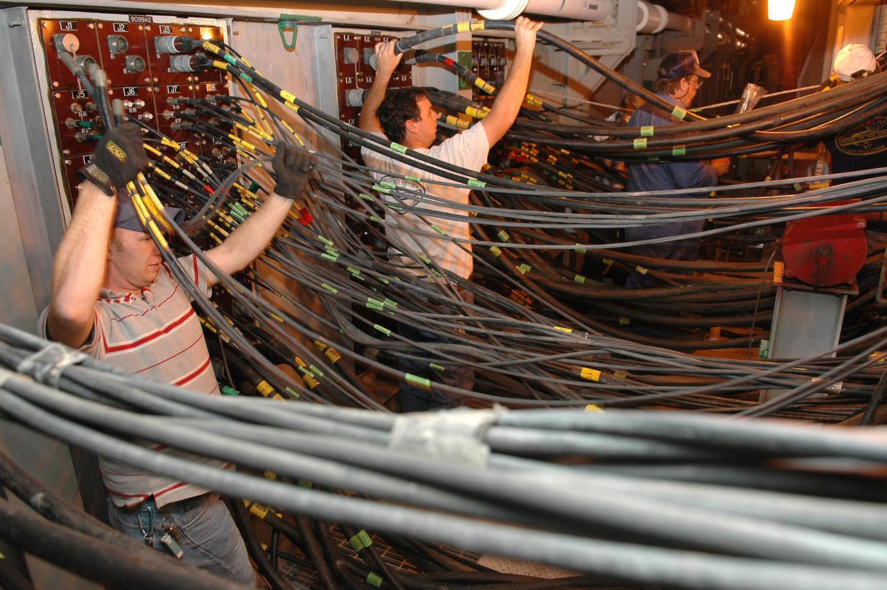
And beneath there are the four [color=blue]Instrumentation Interface Panels[/color], which I will try to get a little bit sharper than the ones from the Paper Kit, ![]()
whereby I’m favourably impressed by this cable jumble during the MLP cabling on the pad again and again. 
And now to the Side 4, on which there are also some things (marked in red) that should be corrected. ![]()
First of all, there is the box on the frame in Bay 13, which is wrong there and is omitted, but for which the old box is mounted in Bay 10.
And then I must unfortunately dismantle the two lower Pneumatic Vent Mufflers, because they did not exist yet during the STS-6, as I have only now noticed what one can see in this image of the STS-8, which was launched four months later.
Source: NASASpaceFlight.com Forum (Ares67)
But either I build my pad after the historical original, or I let it be, and therefore they must be removed, whether I like it or not. ![]()
At the beginning, I naturally confided in the correctness of the design in David Maier’s Paper Kit and reproduced the details, especially since I had neither special detail knowledge nor useful reference photos of the STS-6.
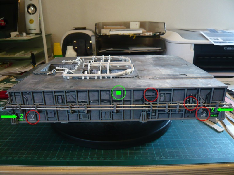
Today, however, I have a pretty good overview, and so I noticed when studying the fantastic threads of the early missions by Ares67 that the MLP numbers in the kit, especially on the Side 4 do not sit in the right places, ![]() but rather where I have drawn them (green).
but rather where I have drawn them (green).
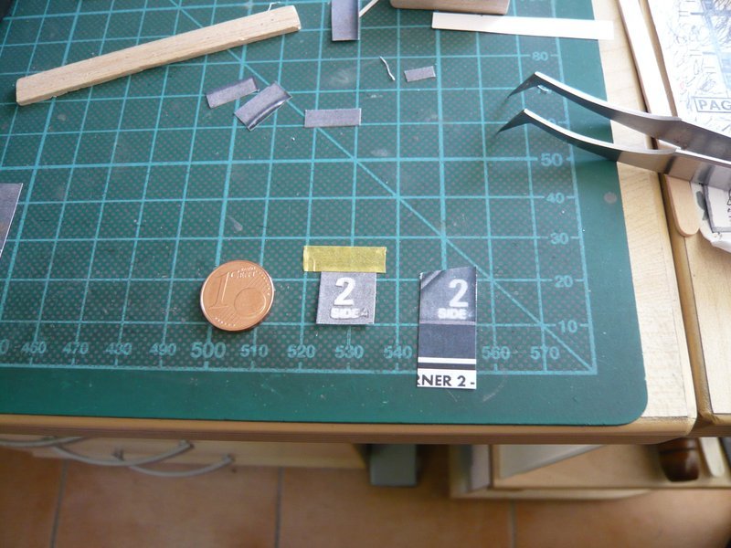
Almost, I wanted to take over these identifiers from the STS-8, but then I still have discovered an image of the STS-6, which shows, that the rear identifiers of the STS-6 looked differently. ![]()
It was this image here, on which the front identifier is concealed, but for this the end of the page is to be seen, on which one would be able to recognize something perhaps with a corresponding zoom, I thought at least.
Source: nasaspaceflight.com Forum (Ares67)
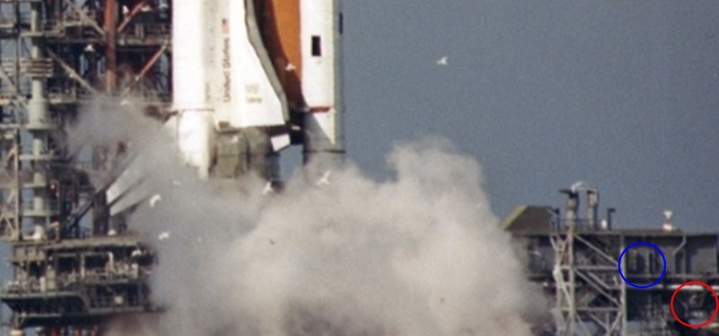
And I was lucky, because that is indeed the case, as you can see on this image. ![]() There one can hardly see yet, that the rear identifier is not completely placed in the Bay 18 but in the Bay 18 (red circle). However, because there is little space, due to the the pipe support and the crossbars on which it sits, the 2 is above the lower strut, and the identifier Side 4 beneath it.
There one can hardly see yet, that the rear identifier is not completely placed in the Bay 18 but in the Bay 18 (red circle). However, because there is little space, due to the the pipe support and the crossbars on which it sits, the 2 is above the lower strut, and the identifier Side 4 beneath it.
At the same time, it can be seen that there were only the two upper Vent Mufflers (blue circle).
And thus I can also consider and correct this disagreement. ![]()
And finally, I’ve still tried, wether the Instrumentation Interface Panels can still be improved, wherefore I have copied them from the Street View shot of the MLP-1 and reduced it to 1:160.
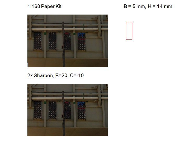
And that should be quite possible, I think. ![]()
![]()
Hello everybody,
here comes at last the next update. ![]()
But in the implementation of the latest ideas and details, new questions emerged, which I had yet to pursue, in order to clarify their structure. ![]()
Therefore, in sequence, and thus first to the [color=blue]Interface Panels[/color] at the end of the [Side 2(), which looked as in this image using the template from the Paper Kit.
And now these are the panels taken from the MLP-1 (Street View) and scaled, which look a little clearer,
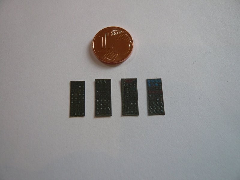
and also at the MLP look quite well, at any rate better than the previous blurred paper Kit panels. ![]()
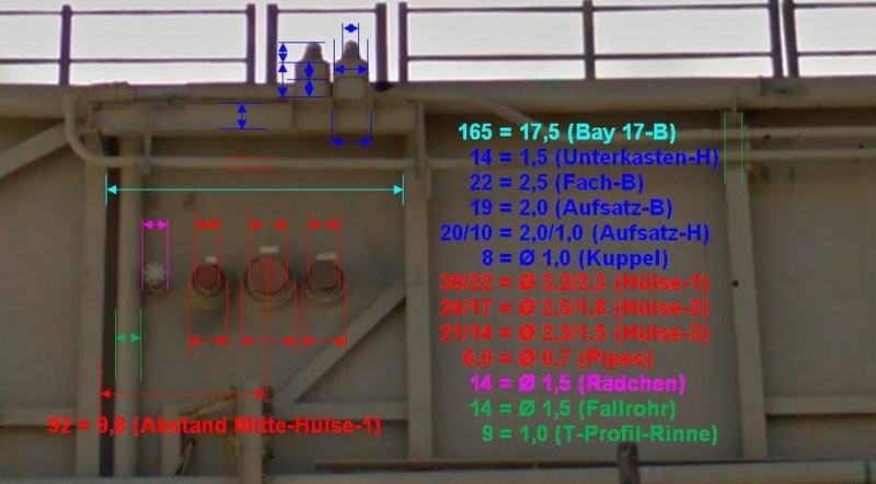
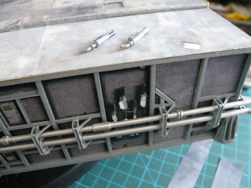
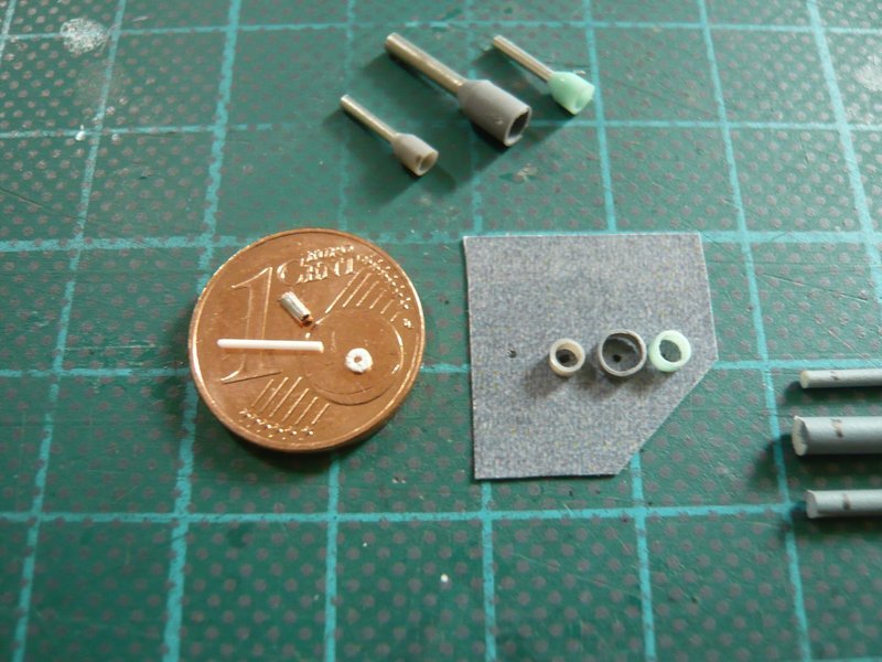
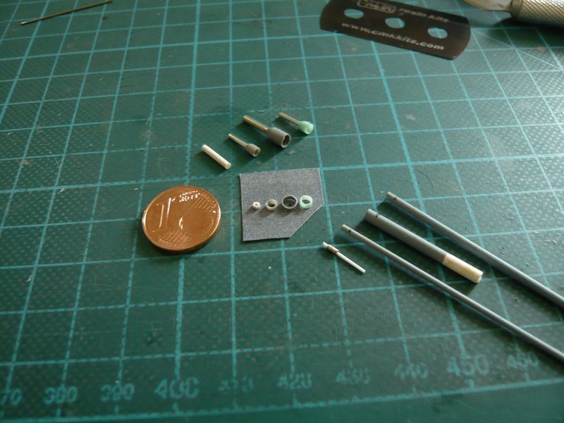
And so to the next details in Bay 17, the red indicated ports for the ECS Purge lines, which I wanted to scratch by simple round bars with red caps. ![]()
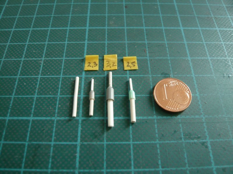
However, on closer inspection, it can be seen clearly that these ports consist of through-sleeves, in which are the connecting sockets of the purge lines, at which the red ventilation hoses of the MPPU are linked. ![]()
After some consideration, I remembered the wire end ferrules already used for the lampshades. And these are not only available as pure metal sleeves, but also with plastic sleeves, which can be easier cut off to the required lengths than the metal sleeves. ![]()
And as a result of my usual scaling,
I have come to the following sleeve types, whose diameters would fit perfectly, into which then the matching connecting sleeves made of round bars are glued and red caps are painted. ![]()
Later, it goes on with the reconstruction work on the Side 4. ![]()
![]()
Incredible detailing, and theres going to be even more pipe work !! I had forgotten about the structures outside areas … ![]() Top work
Top work ![]()
Thanks John for your compliments. There is still something to do. ![]()
![]()
Hello everybody,
since in the laying of the two thin pipes on the Side 2]() inevitably the "roof"gutters come into play,
Source: apollosaturn.com (John Duncan)
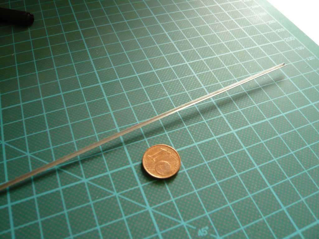
I have made a couple of new attempts in the meantime to get some bending feeling again, because unfortunately there is nothing off the shelf.
For my first attempts at the very beginning of the project, I got an aluminum tube Ø 2 mm and filed down carefully the upper half with a fine mill file, which basically works, but which was quite elaborate and laborious. ![]()
Therefore, from today’s point of view, I would rather want to return to the already tested variant of moulding a sheet metal strip over a round bar.
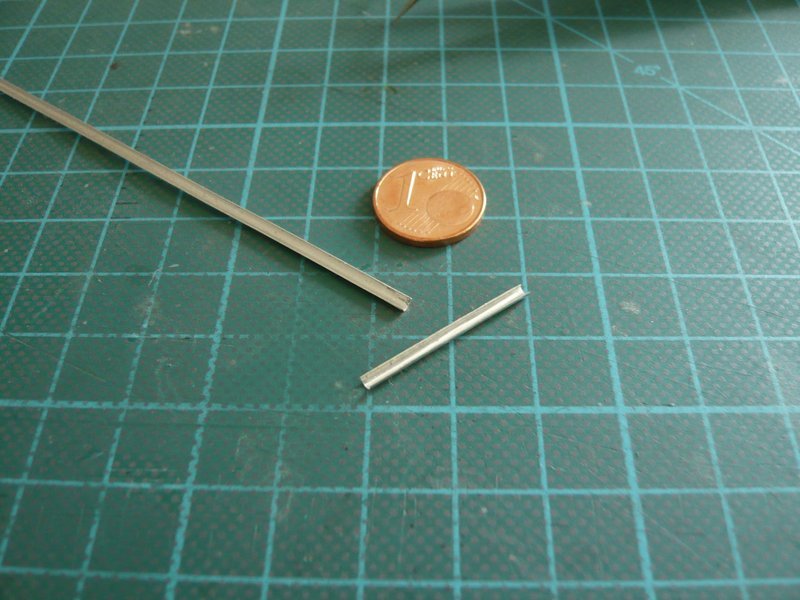
For the back Gutter 3 over the Bay 18 I need a 23 mm long piece, after it follows an elongated substructure, on which two sockets with connection stubs sit, whose purpose of use I have not yet been able to find out however. But no matter, maybe I still can discover it. ![]() And as it looks like, the two thin pipes seem to be attached to these sockets when I see this right.
And as it looks like, the two thin pipes seem to be attached to these sockets when I see this right.
This is indeed a picture of the MLP-1,
but on the MLP-2 this part looked similar, as one can see on this image detail, only the two sockets sit more in the middle.

Source: apollosaturn.com (John Duncan)
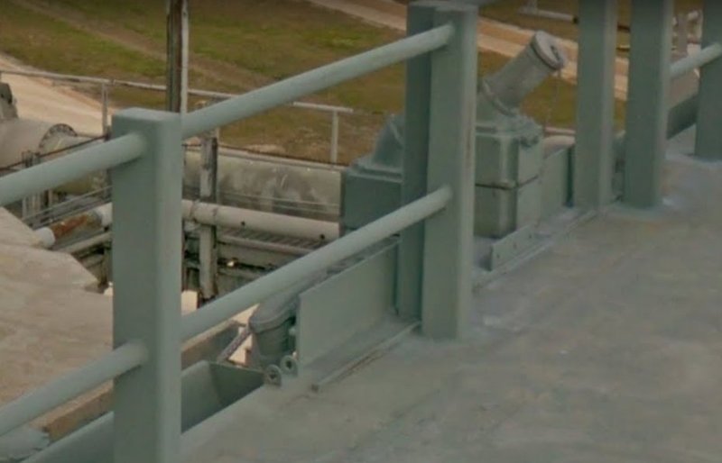
On this panorama one can see the details more clearly.
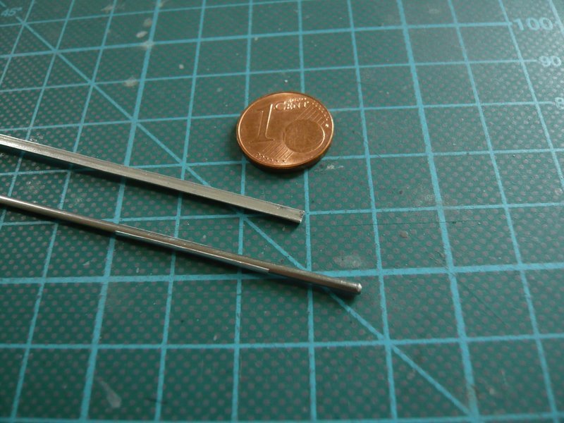
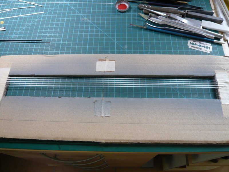
This time I’ve used thin aluminum sheet (0,2 mm) for the gutters, cut out a strip of 23 mm x 3 mm and molded it over a round rod Ø 1,5 mm, but the strip can also kink axially, instead of curving itself evenly, which should be better prevented. ![]()
Here one can see the filed down pipe (above) and below it the molded gutter piece, which one can do more precisely than by filing.
In order to prevent this axial kinking, I will lay the strip on a rubber pad on the next attempt and then press down the round bar from above, perhaps it will work better then. ![]() However, how good this can be done with the longer strips, we will see then.
However, how good this can be done with the longer strips, we will see then.
Afterwards, I started with the face lifting of the Side 4, on which there are also some pipes and cables, which I would like to scratch. And since they lie above the vertical struts, then the 2D textures and shadows on the wall template disturb the picture, which would certainly look comical, especially since the 3rd dimension is missing anyway. ![]()
So I have started to cover the Bays on this side with matching parts, which was quite tedious because one had to measure all the fields and covers before, so that they fit into the fields.
Then came the Bay 16 with the four Vent Mufflers, where I first removed the two lower mufflers. But since the shadows there just look too brutal, ![]()
I then also removed the two upper Mufflers to be able to cover this bay completely new. And the front and rear MLP-2 identities have meanwhile also been renewed and were placed in the right bays.
Afterwards, the two vent mufflers were glued again, which now looks much better and corresponds to the original. ![]()
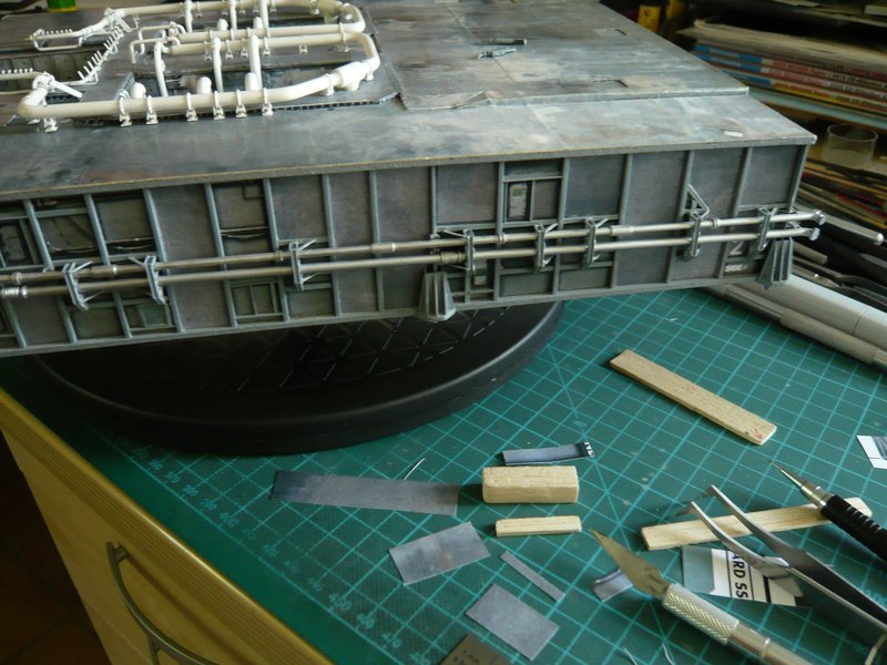
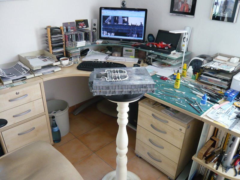
In order to have more freedom of movement, I’ve put my turntable on a stand to have easy access from all sides, which makes the work much easier. ![]()
Now only a few fields have to be renovated, which will be done tomorrow.
As far as for today, and thank you for watching. ![]()
![]()
Looking amazing buddy. It’s always very educational to read every update. Perhaps, after this journey is finished for all of us then maybe I can apply at NASA and they will hire me also. I will have scientist prospective and eyesight on all things space shuttle and put them back in business ![]()
![]()
Thanks Mike for looking in on me again and thanks for your nice compliment. ![]()
One should never say never, good luck at NASA. ![]()
Hello friends,
now also the last fields on the Side 4 are newly re-glued, which looks now like new-born,
compared to the side from the paper kit

and only awaits their details. ![]()
And because we are dealing with cosmetic, I have attached the yellow markings on the LH2 Vent Line, seven in number, as can be seen on this image from the STS-8.
In order that the somewhat bulky little decals can easier cling around the pipe, I had to use Decal Soft again. ![]()
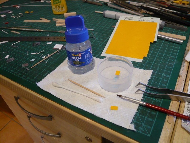
And that’s how it looks on the MLP. ![]()
After the “renovation” of the side walls they look indeed a little bit bald, but now I could finally start with the detailing, first on the Side 2.
I am still in the dark, which especially concerns the detail structure of this side during the STS-6, which does not make scratch-building easy. ![]()
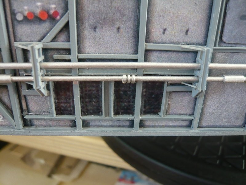
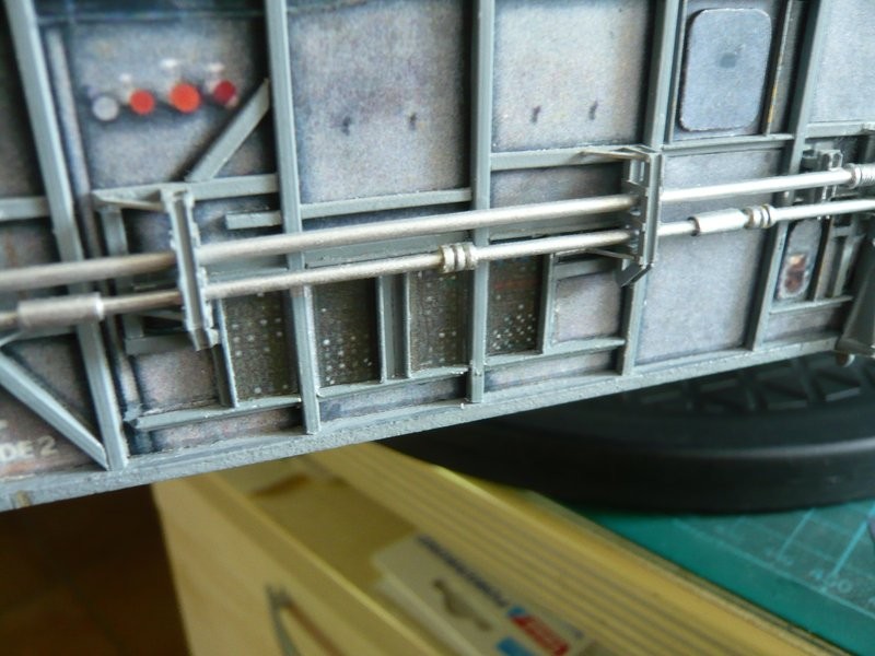
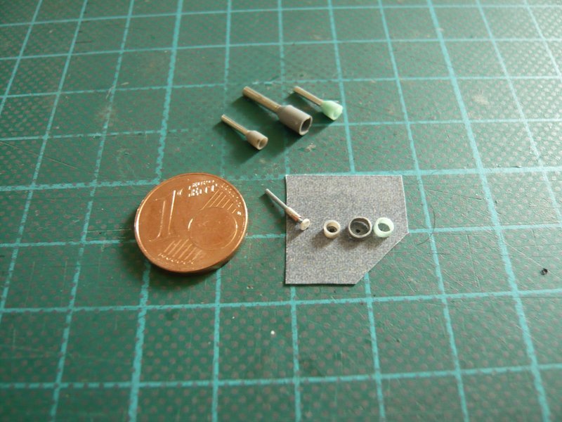
I started with the through-sleeves and connecting sockets of the three ports for the ECS purge lines,
for which I have separated 1 mm wide rings from the wire end ferrules, which protrude forward on the wall.
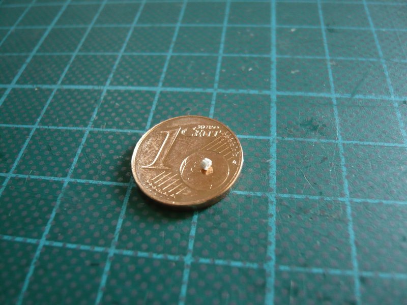
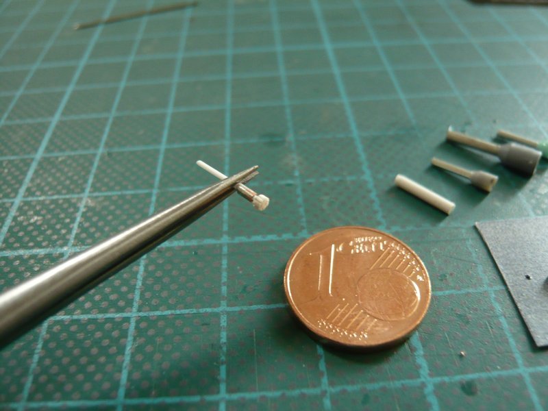
The small connector to the left beside the downspout belongs to a GN2 pipe, the front of which looks like a handwheel and also sits in a through-sleeve, what I then have tried to scratch laboriously. ![]()
The sleeve is a piece of a wire end ferrule (Ø 1 mm) and the wheel is from a section of a rod (Ø 1 mm), which I tried to slit all around with the cutter. ![]()
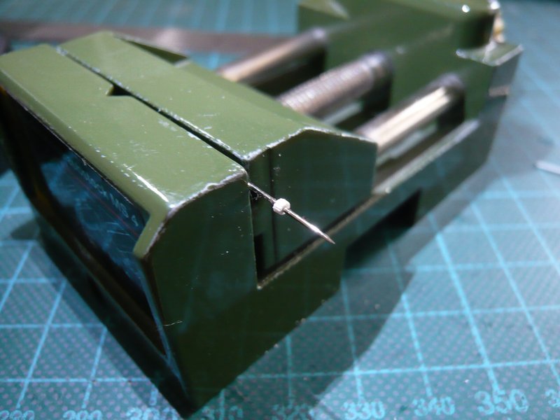
On the right lay the round bars for the connecting sockets.
And so this part in the sleeve looks so far, an attempt was worth it at any rate. ![]()
![]()
I have no more words
Superb as always ![]()
Hello friends,
thank you for your interest and stay tuned. ![]()
Hello everybody,
then I tried to paint the caps of the connecting sockets red, first times with two test rods. ![]()
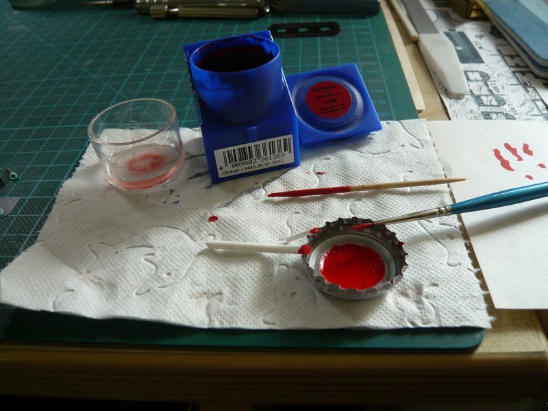
Since the lengths of the caps with the brush by hand are not to manage with uniform lenght, I have masked the rod tops accordingly.
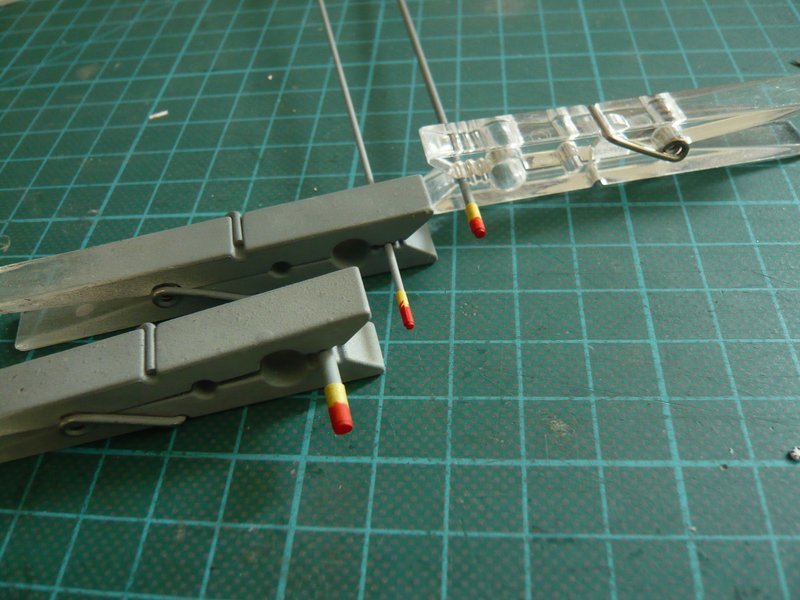
And now it looks better, to the left is a second variant of the handrail, which has only a thin disc at the front, which corresponds more to the real part, which is more likely a blind flange,
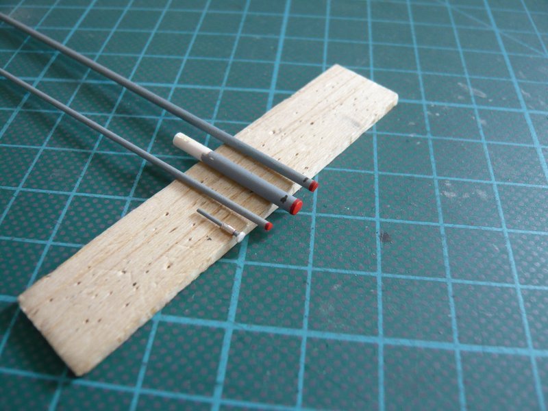
as I have now found out. ![]()
Since I would like to paint the small through-sleeves by Airbrush, I have pinned the parts on my Balsa-Holding strip, which I had used for the lampshade lacquer.
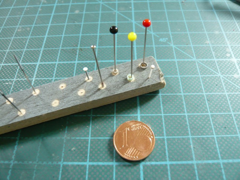
And in this airbrush job, also a few profiles for the pipes on the side walls will be sprayed, which I have already prepared.
These are, inter alia, the two lines with the double kink,
Source: apollosaturn.com (John Duncan)
whose connection on this console with the two attachments was a mystery to me until now. ![]()
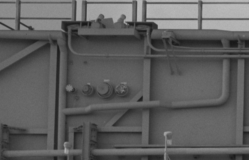
In the meantime, NASA has also digitized the photos contained in the so called MLP-Report and made them available online, from which I have already taken a lot of detailed information. And these reference photos (unfortunately only black and white) are predestined for detail studies because of their high resolution. ![]()
In addition to this image as JPEG (316 KB), on which one can not see enough details, there is also a huge TIFF format (38 MB), ![]() on which one can clearly see that the two pipes are actually connected to these two attachments, which I had so far only suspected. And on this image one can also see that the front part on the GN2 Line is probably a blind flange.
on which one can clearly see that the two pipes are actually connected to these two attachments, which I had so far only suspected. And on this image one can also see that the front part on the GN2 Line is probably a blind flange. ![]()
This version of the connectors with the covers is only available on the MLP-3, on the MLP-2 they are missing , as one could already see on this earlier image.
In any case, similar connector caps are located in front of the attachments, as can be seen from this perspective.
That this connection console was still slightly different on the MLP-1, can be seen in this image. ![]()
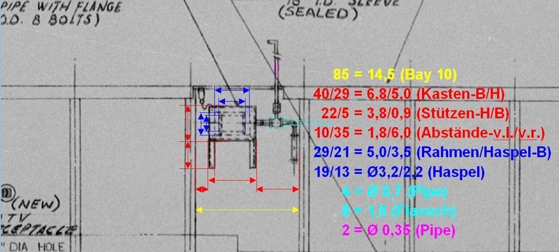
The MLP-Report contains, among other things, also a drawing of the Side 2 from which this image section comes, from which I have determined the dimensions of the box (Fire Hose Reel).
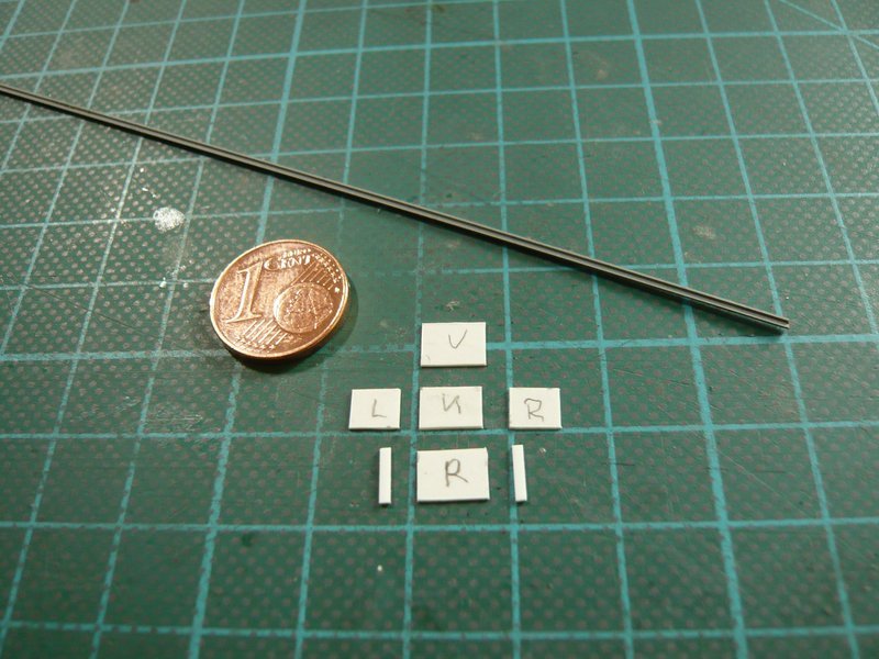
And these are the prepared parts for the box of 0,3 mm Styrene with two support struts (0,5 mm x 1 mm), whereby I assume that these were more likely angle profiles, for which I could use an already painted brass profile (1 mm x 1 mm).
So much for the theory, which I now only need to put into action. ![]()
![]()