Lovely precise work Manfred, and super skilful ![]()
1 Like
Thanks John. ![]()
Hello everybody,
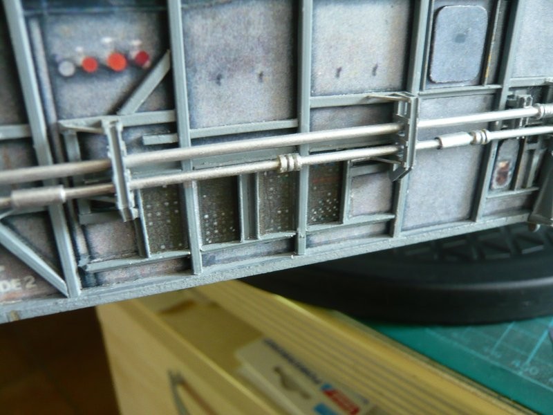
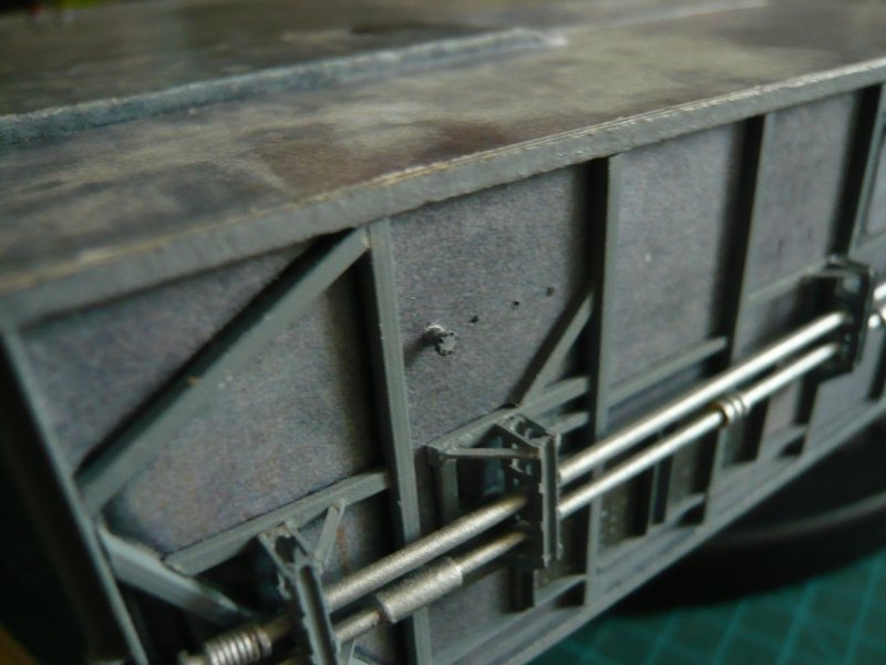
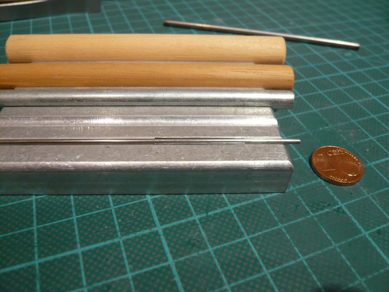
today only a short flash from a first attempt to bend the two thin pipes. ![]()
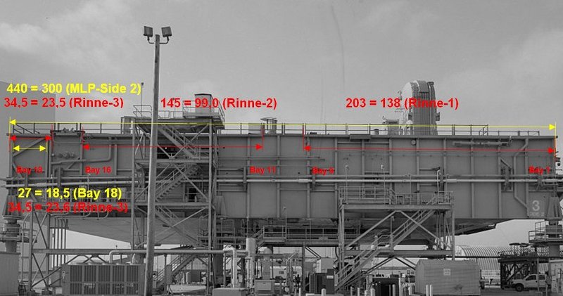
For this I have used copper wire Ø 0,6 mm and a copy of the Side 2 of the MLP-3 as bending template, which is why I had to correct the double kink a little bit. ![]()
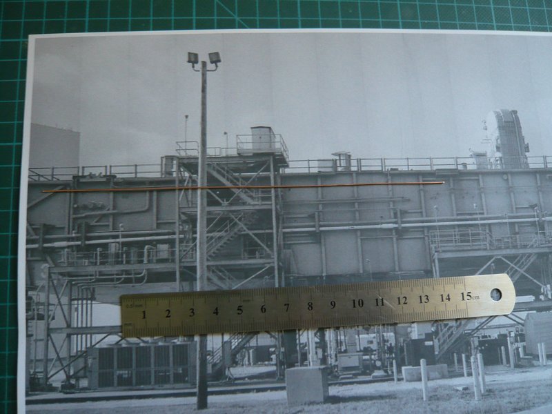
And these are the two pipes in the raw state, from which the left ends are now adapted to the attachments on the console and the right ends must be shortened and angled.
Sorry, but the light conditions are unfortunately not the best. ![]()
That was it already for the moment. ![]()
![]()
5 Likes
Hello friends,
and thus to the next pipe on this side, whereby I assume that it is a Firex line. The same line there is also on the [Side 4/color, to which we will come later. ![]()
This pipe is a bit thinner than the first two pipes, it starts somewhere in Bay 13 and then it takes the marked course to the front corner of Side 2,
Since on this image one can recognize the beginning of the line unfortunately just as little as on this image of the MLP-2, ![]()
Source: apollosaturn.com (John Duncan)
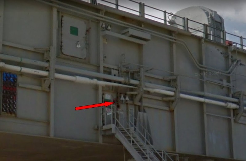
I have consulted again the Street View panorama of the MLP-1. And here I have found a suitable perspective, on which one can recognize, ![]() that the line comes out of the wall of the lower MLP-B Level to the right of the door and then runs first to the top and then to the right.
that the line comes out of the wall of the lower MLP-B Level to the right of the door and then runs first to the top and then to the right.
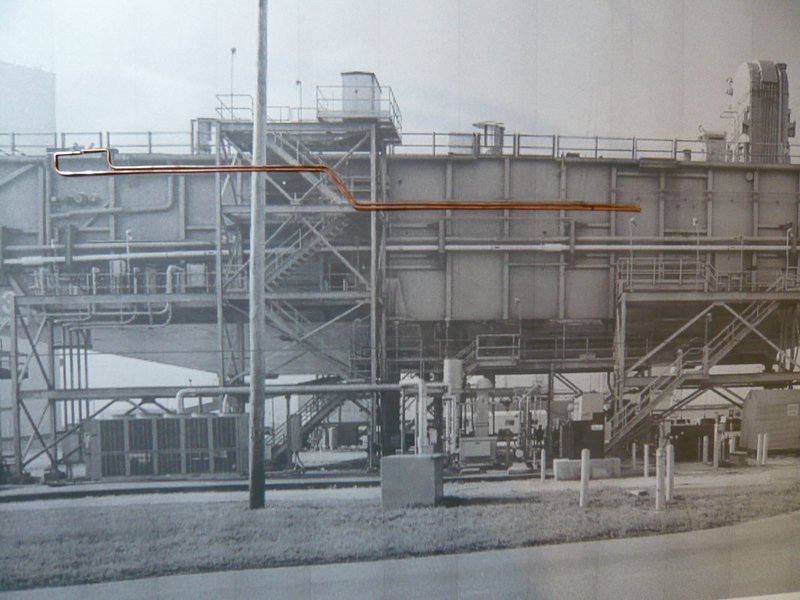
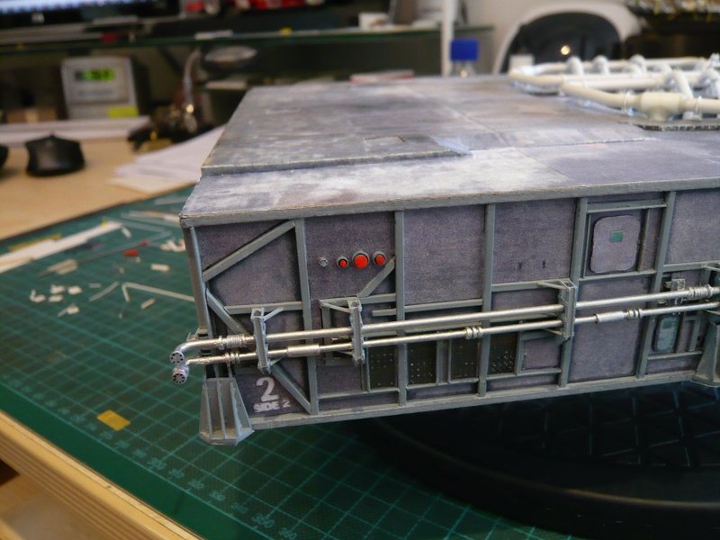
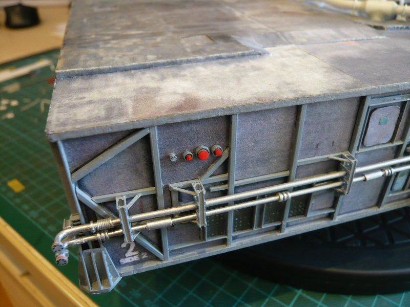
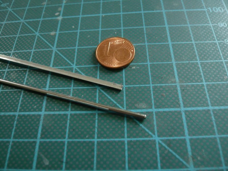
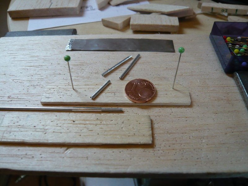
Compared to the first two pipes (Ø 0,6 mm), this line should have a diameter of 0,4 mm, for which I also used Cu wire. ![]()
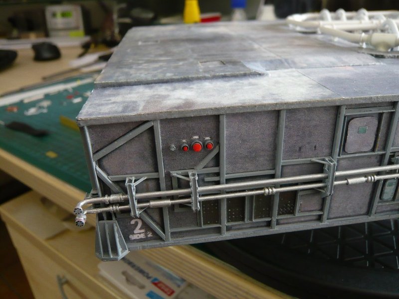
And here the test line is temporarily layed down, but at the lower end it must be shortened and angled.
At the other end of the line at the front corner to the Side 1, I was initially not quite clear about their real run during the STS-6, provided that it already existed at that time. ![]()
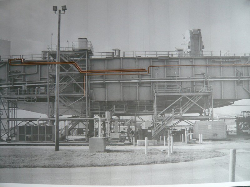
As can be seen in these images from John Duncan’s collection (1998), the line runs around the corner to the Side 1,
Source: apollosaturn.com (John Duncan)
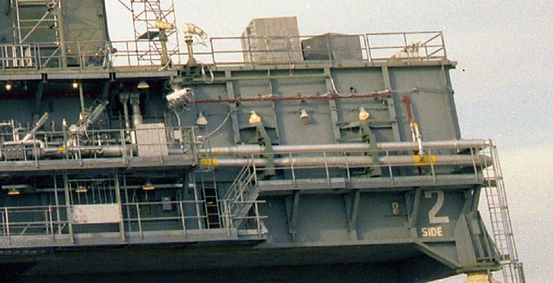
and flows then in the thicker Firex main line, which is running under the Blast Shields to the other end of the side and then onSide 4, where it ends in Bay 13. ![]()
Source: apollosaturn.com (John Duncan)
And now comes the surprise, ![]() linked with a fat ?
linked with a fat ?
On my standard reference image of the STS-6 one can see that there was no continuation of this Firex line behind the corner on the Side 1, maybe it was extended only later up to the main line, but it is only questionable when, respectively whether at all? ![]()
Obviously, there is something else, whereat the red arrow points, to what I’ll come back later. ![]()
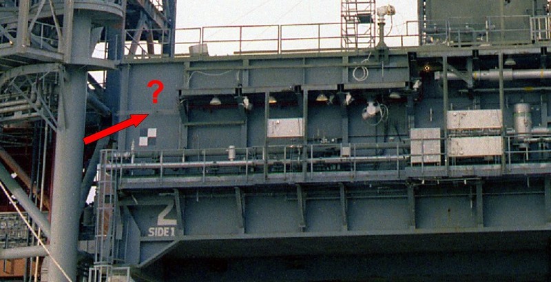
Source: retrospaceimages.com (STS-6)
To the right side of the Side 1 it looks similar, where the red Firex main line ends in front of the corner and only some cables run around the corner. ![]()
Source: retrospaceimages.com (STS-6)
And so I have arrived at a point where I have to rethink everything, because that would mean that I can save myself the thinner pipe apparently, because it still did not exist at that time presumably. ![]()
But about it I just have to sleep tonight … ![]()
![]()
5 Likes
Hello everybody,
well, so is it with the details, which I wanted to start scratching, but which on closer inspection suddenly vanish into thin air … ![]() Therefore it is absolutely necessary to take care to the mission they are based on and whether they are relevant to the own mission.
Therefore it is absolutely necessary to take care to the mission they are based on and whether they are relevant to the own mission. ![]() But that I did not keep in mind at [John Duncan’s[/color] MLP-2 images of 1998, because I was so thrilled about their details, a typical case of Not a bit of it!
But that I did not keep in mind at [John Duncan’s[/color] MLP-2 images of 1998, because I was so thrilled about their details, a typical case of Not a bit of it! ![]()
Afterwards one is unfortunately always smarter, but aside from the STS-1, there are relatively few usable Hi-Res images from the first missions, especially from Side 2, where it unfortunately looks gloomy. ![]()
That’s why I took the trouble and have specifically investigated the first MLP-2 missions until the end of the 80s once again, finally to get information about these ominous Firex Lines.
And these were the following missions:
Challenger:
1983: MLP-6, MLP-8,
1984: STS-41B,
1985: STS-51B, STS-51F,
1986: STS-51L;
Discovery:
1984: STS-41D, STS-51A,
1988: STS-26;
Atlantis:
1985: STS-51J, STS-61B.
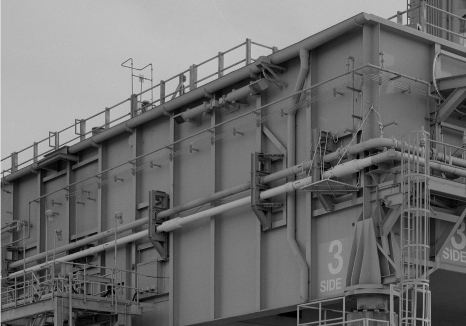
And in doing so, I found out, that 1983 during the first missions, there was no transition of the Firex line from the Side 2 to the Side 1, but first in 1984 at the Challenger mission STS-41B, as one can clearly see in this image, especially with zoom. ![]()
At the previous mission STS-8, this transition did not yet exist, as one can see on this image unfortunately not so sharp, but nevertheless. ![]()

Source: NASASpaceFlight.com Forum
What one can see as a shadow is the detail (?) on MLP-2, what I’ve already mentioned in the last post, which I will now still examine carefully. ![]()
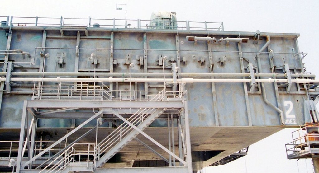
And therefore back to the Side 2 of the MLP-2 (1998), on which one can see it also only schematically in the zoom. ![]()

Source: apollosaturn.com (John Duncan)
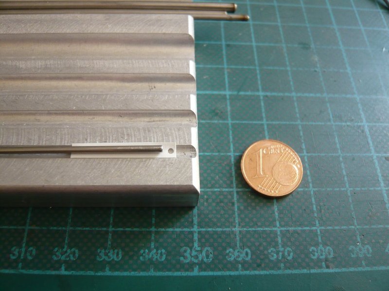
These are actually four thin Fuel cell pipes (Ø 0,5’’ = 12,7 mm) for the fuel cells of the orbiter, namely the two upper GO2 pipes and the two lower GH2 pipes. ![]()
More clearly, this bundle is seen on this image from the [color=blue]MLP-2[/color] at the STS-132.
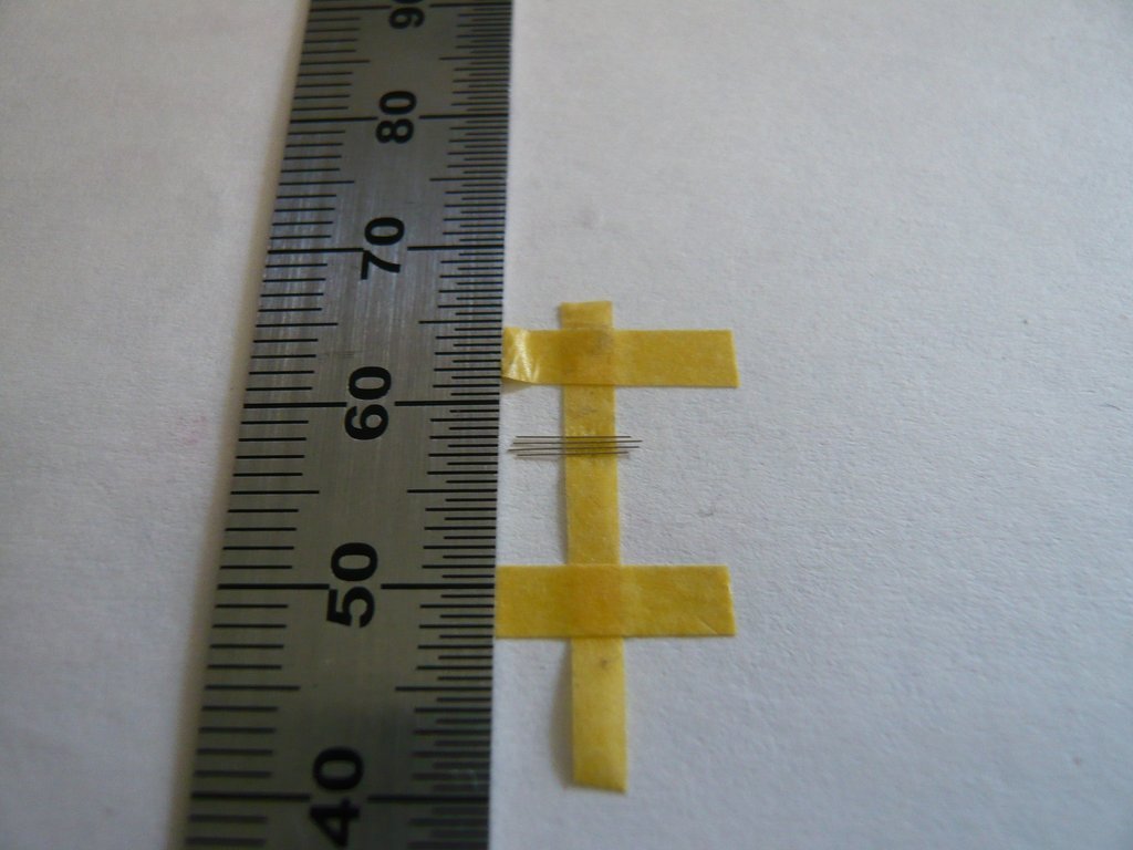
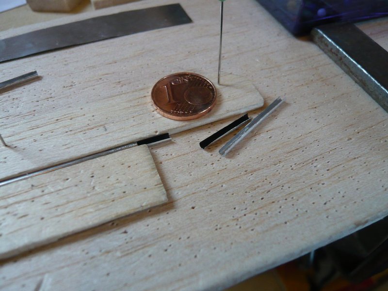
If one really wanted to scratch these four pipes, one would need wires with a diameter of about 0,1 mm, ![]() which I have procured some time ago.
which I have procured some time ago. ![]()
BTW, here is such a wire (Ø 0,1 mm) in cosy togetherness with a hair (Ø 0,05 mm) of mine,
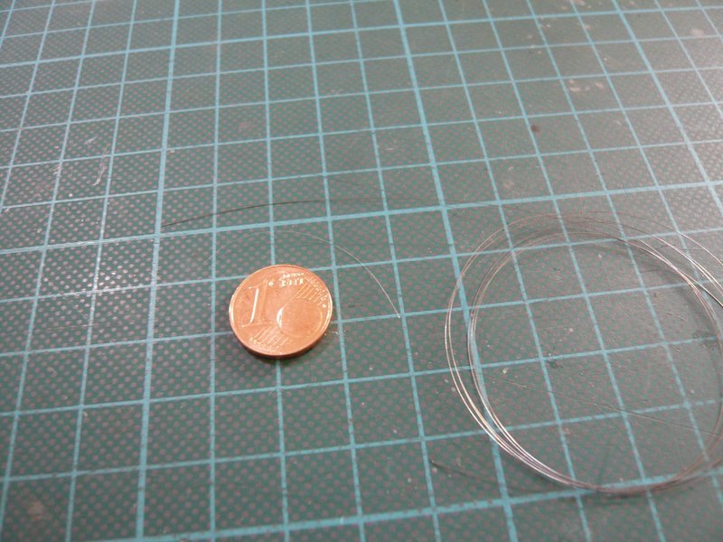
whose color however will not be betrayed. ![]()
![]()
7 Likes
Great in depth research for this. I wonder how many miles of pipework there are on this ?
1 Like
Thanks John, but now try to imagine the whole Launch Complex. ![]()
It’s simply unbelievable. ![]()
![]()
1 Like
Hello everybody,
I’m still wondering if I should try it with the 0,1 mm wires. ![]()
This would mean that I had to glue the four thin wires (0,1 mm) parallel to each other on supports strips 1,5 mm x 0,35 mm and then to glue this thin wire bundle over the length of about 12 cm from the Bay 8 to the Bay 1 and also still around the corner to Side 1, so that the wires remain tensioned. 

But this structure would have to be painted before, which sounds utopian, ![]() unless one is building an intelligent retaining jig …
unless one is building an intelligent retaining jig … ![]()
Now good advice is expensive … ![]()
But on the other hand, nothing is impossible! ![]()
![]()
7 Likes
Hello everybody,
this is certainly a rather demanding and complicated undertaking, which would in any case require a suitable holding jig to be able to paint this wire bundle by airbrush in a first step. ![]()
Meanwhile I have fiddled around with a solution and have also an idea already. ![]()
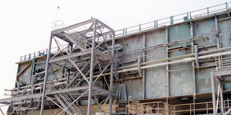
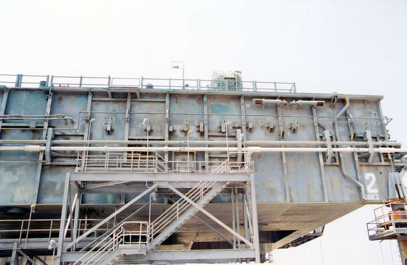
One would have to reproduce the girder structure of the Side 2 from Bay 8 to Bay 1, which can be seen in this image,
as a kind of template made of Balsa with the tiny supports strips on girder dummies, and glue the wires on it, whereby the front ends as well as the rear ends should have to be angled already and fixed somehow. ![]()
The other pipe supports, sitting on feet on the side wall, would have to be painted and glued separately, and then one could glue the painted thin bundle with the support strips onto the girders and the other wall supports, and also lay around the corner. ![]()
This sounds surely a bit adventurous and perhaps it’s hard to understand too, but maybe it’s possible. ![]()
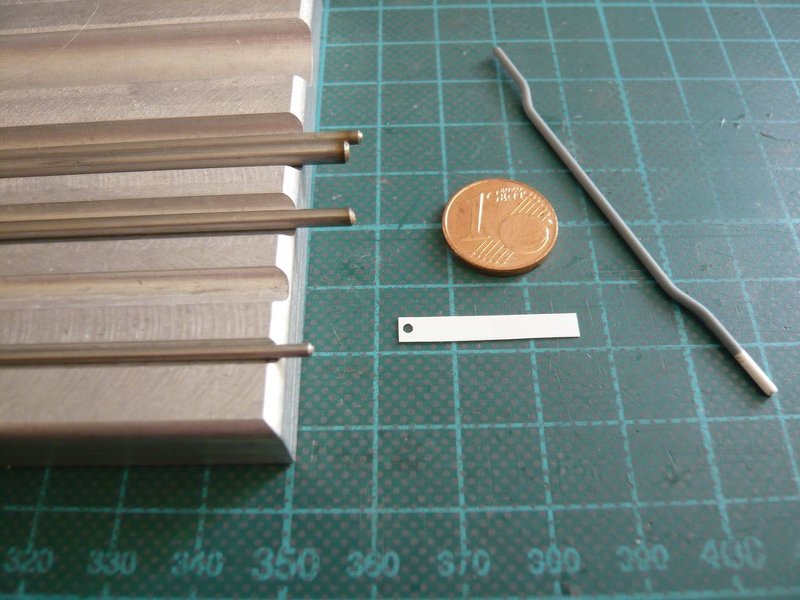
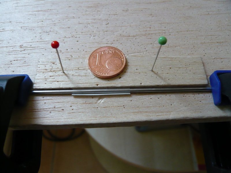
The difficulty results from the minimal distances of the four thin wires from only 0,2 mm on the 1,5 mm short support strips. ![]()
This filigree arrangement of the wires I have tried to apply now. First I used spring steel wire 0,1 mm, which is unsuitable because the wires are magnetically attracted by the tweezers. ![]() But with nickel [silver wire 0,1 mm] it was possible and looks like this.
But with nickel [silver wire 0,1 mm] it was possible and looks like this.
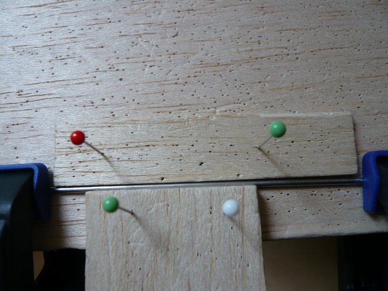
This is my momentary idea, but maybe it is also too crazy ![]() and cannot be realized, wherefore I’m still a little bit skeptical,
and cannot be realized, wherefore I’m still a little bit skeptical, ![]() although my feeling tells me that it could work …
although my feeling tells me that it could work … ![]()
![]()
4 Likes
Hello everybody,
while the holding device assumes more and more shape in my mind’s eye, I also have to understand the course of the Fuel Cell Pipes, especially their starting points on the Side 2 in the Bay 7 (GH2) and Bay 8 (GO2), as well as their further course to the MLP corner and then on the Side 1. ![]()
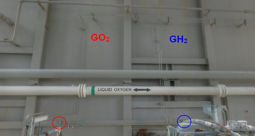
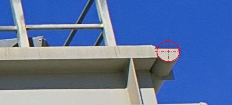
For this purpose here are a few pictures for illustrating the wiring course, for the sake of simplicity, just behind the corner on the Side 1, whereby the two upper lines are the GO2 Pipes, and the two lower ones the GH2 Pipes.
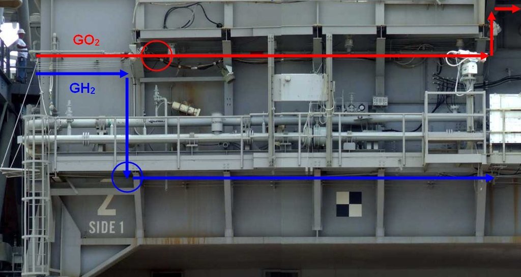
While the two GO2 Pipes are running below the Blast Shields to the LOX Tunnel, the two GH2 Pipes run downward in front of the Blast Shield and then below the AccessPlatform up to the LOX Pneumatic Interface Plate in the Bay 6.
And so it should fully suffice if I let end up the pipes at the circled places, especially since one can not see their further course on the model. ![]()
But regarding the starting points of the Pipes on Side 2 in Bay 7 and Bay 8, it’s still not quite clear in detail, because one can not recognize it exactly enough, which is why I initially thought that the pipes would come out of the MLP wall. ![]()
Source: apollosaturn.com (John Duncan)
And even this image, which reveals more details already, cannot give a more exact explanation.
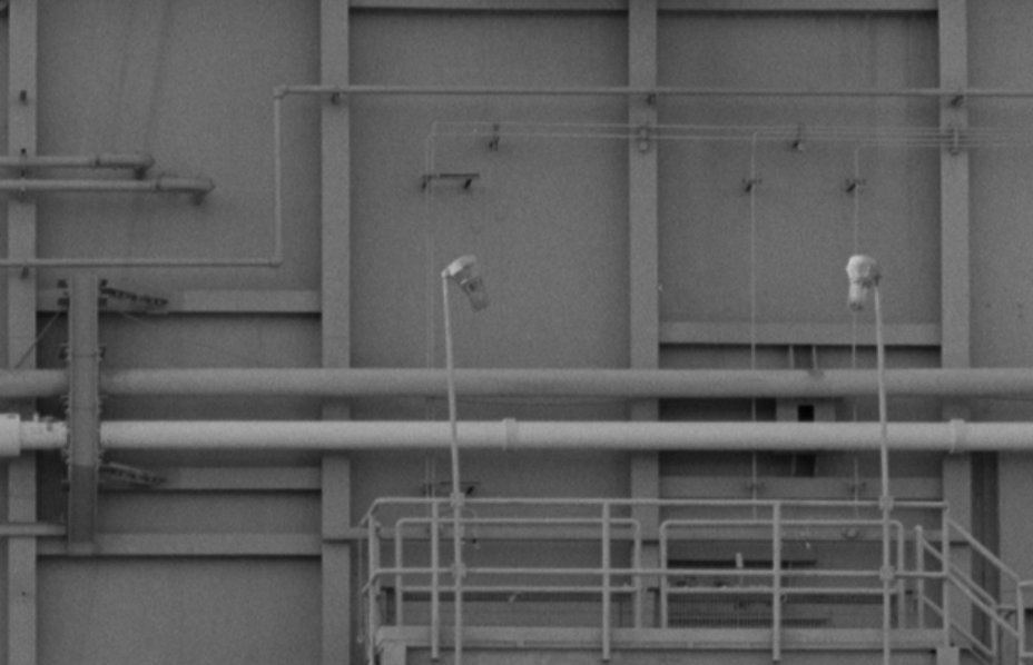
It is only clear that the two GH2 Pipes in the Bay 7 running down close to each other, while the two GO2 pipes in the Bay 8 run with a significantly larger distance. ![]()
But then suddenly I remembered, ![]() that there is a NASA panorama with a great view of the Side 2 of the MLP-2 from Level 75 on the FSS, on which these two bays might be visible more detailed.
that there is a NASA panorama with a great view of the Side 2 of the MLP-2 from Level 75 on the FSS, on which these two bays might be visible more detailed.
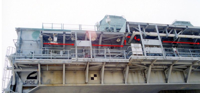
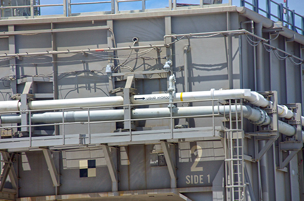
And lo and behold, quite right, and therefore here the ultimate shot, unfortunately without the linked panorama, which is no longer accessible. ![]()
wherewith (now) almost all the uncertainties for scratching should be eliminated. ![]()
As can be seen, the pipes start on an angle profile and then take a multiple angled course upwards, and follow after merging in the Bay 7 as a quadruple bundle to the right up to the beginning of the side.
As coming from NASA’s plans, the circled jacks are Moisture Sensors, and one can even see how the pipes are bolted to the angle profile.
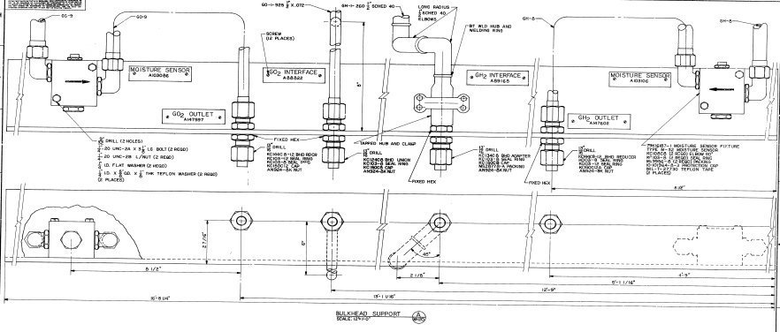
And with that the matter looks already much more friendly. ![]()
![]()
6 Likes
Hello everybody,
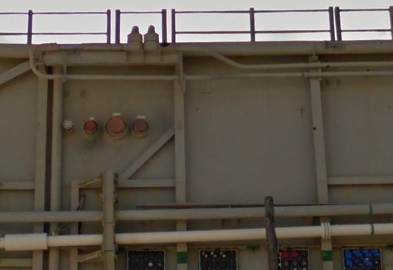
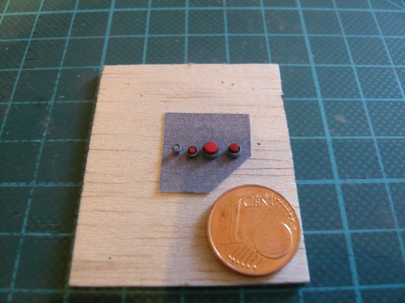
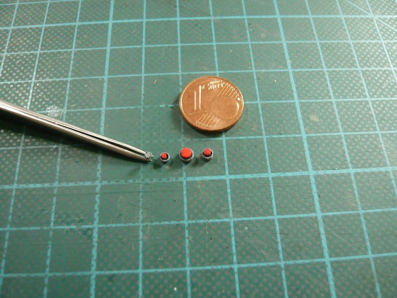
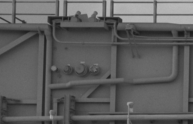
the Fuel Cell Pipes are put aside and let’s look again to the Bay 18,
in which are still to install the through-sleeves and connection sockets of the three ports for the ECS purge lines. ![]()
Here is again the original using the example of the MLP-1.
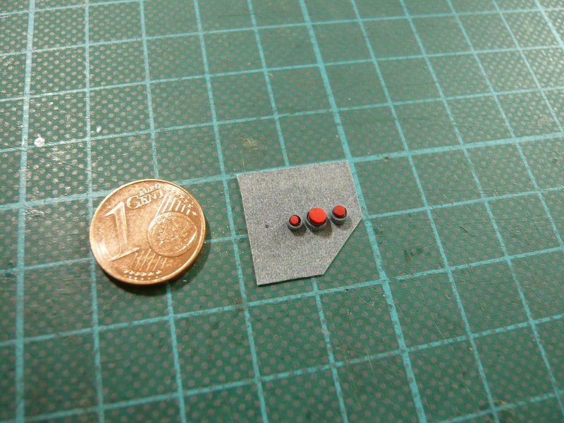
These are the painted and shortened parts,
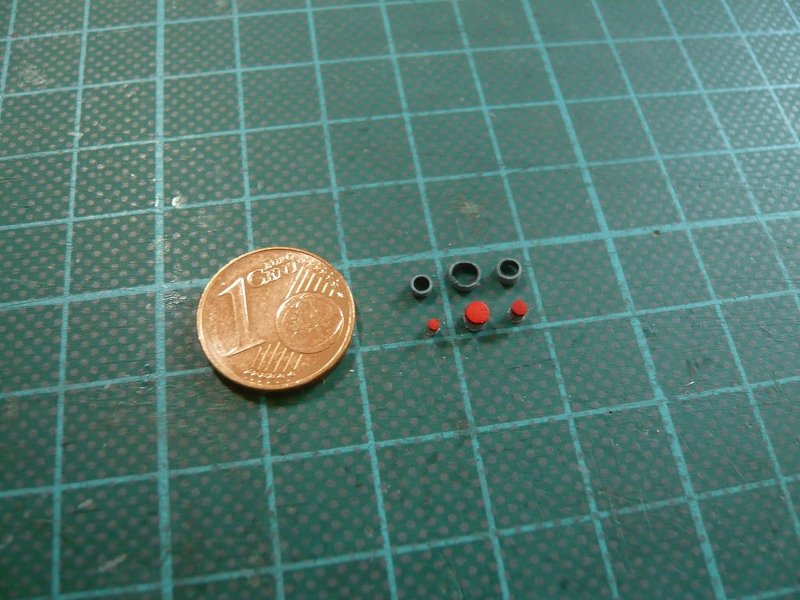

and here on the tailor-made insert.
And here ist still the GN2 line with the blind flange. The eight screws I tried to hint with a fineliner, but what not still convinced me. ![]()
But the next attempt was already better. ![]()

Since the through-sleeve (Ø 1 mm) was somewhat too long, it was inserted into the wall,
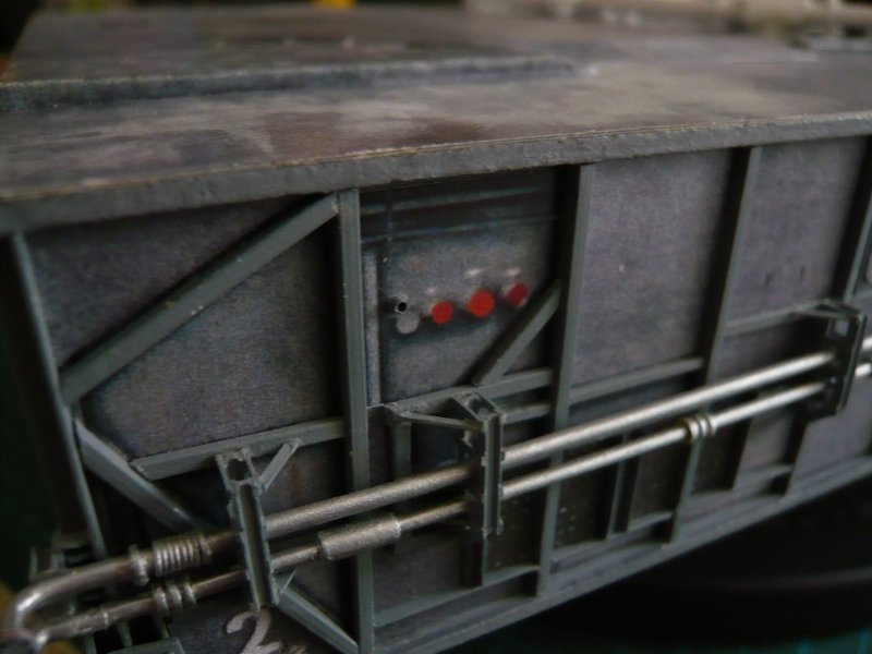
and then the insert was finally glued over it.
The GN2 line was initially inserted only temporarily, since its installation height must match the height of the connection sockets,
which were subsequently glued.
And with this result, I am now quite satisfied, although the too bright red could be mitigated by a final Washing. ![]() But a small thing is still missing, if one looks closely, namely?
But a small thing is still missing, if one looks closely, namely? ![]()
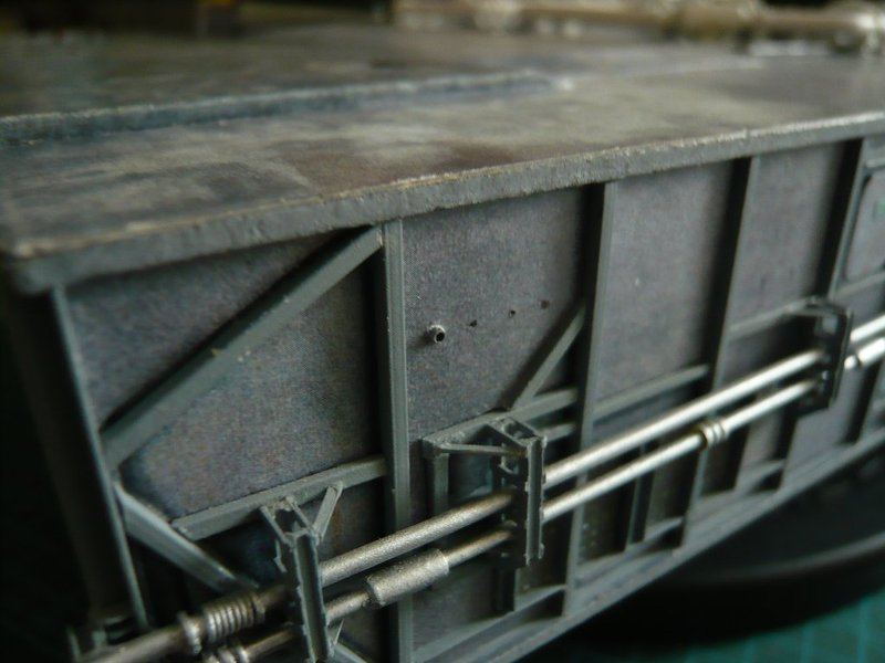
Exactly, the labelings above the three ports are still missing and have been added by carefully removing the color with the cutter. ![]()
Fortunately one must not be able to decipher them. ![]()
And here once again for comparison, how the ports looked before in 2D … ![]()
![]()
5 Likes
The detailing that you keep adding is at a phenomenal level … Superb.
2 Likes
Thanks John, my true follower. ![]()
So that we understand each other correctly, I posted this in the NSF on page 63 on 06/30/2017, I’m now on page 127 … ![]()
![]()
1 Like
Yeah I know this is a revisit of whats been built, but I like seeing it done here with the explanations ![]()
2 Likes
Then stay tuned John and have fun. ![]()
![]()
Hello everybody,
before it goes on in the Bay 17 with the upper console with the two connector sockets,
I’ve been busy myself with the gutters and initially corrected their lengths based on the the MLP-3 photo,
which differ a little bit from the values previously determined at the MLP-1. ![]()
With the Gutter-3 (Ø 10’') above the Bay 18 I had already started. ![]()
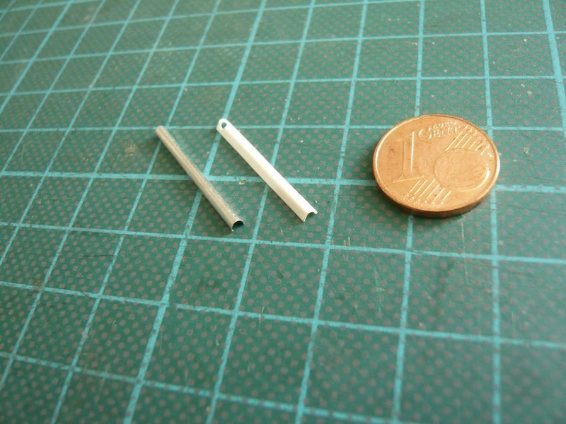
When dimensioning the strips for the gutter, one has to take into account that it does not have a semicircular cross-section as in ordinary guttering on the house, but rather that it extends somewhat beyond the semicircle, as can be seen in this image,
which is why the strip should be slightly wider than half of the diameter, approximately 4 mm.
For molding the strip of 01 mm aluminum sheet over a core wire with Ø 1,5 mm this Rolling Set (thesmallshop.com) is suitable, in which the strip can be bulged in a first step.
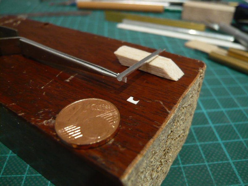
In order to mold the gutter to the final diameter, I’ve also tried my Balsa clamping method from the SSWS Pipes. ![]()
For the first tests, I also used the wrapping foil of a champagne bottle cork. 
And as it looks like, this method should also be suitable for the molding of the longer gutter parts. ![]()
At the same time, I have also tried to use a thin Styrene foil (0,15 mm) because plastic might be advantageous for gluing the supports under the gutters, which would make them more stable.
But since the plastic strip is less ductile than the aluminum strip, it is not easy to buckle it. ![]()
And even after the hot air shower in the Balsa-“Corset”
the result was not so amazing, ![]()
which is why I will probably stay with the aluminum sheet. ![]()
![]()
5 Likes
Hello friends,
the devil is just as always in the details. ![]()
Just when I wanted to start with the tiny supports for the gutters,
I have noticed that I have to correct the dimensions once more, because I noticed a thing only now, which I have so far overlooked. ![]()
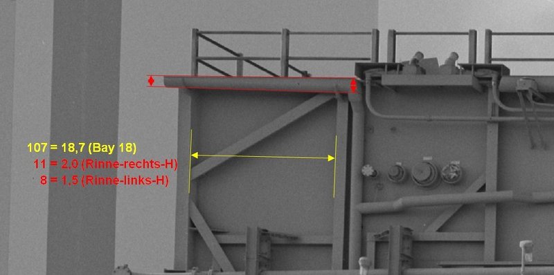
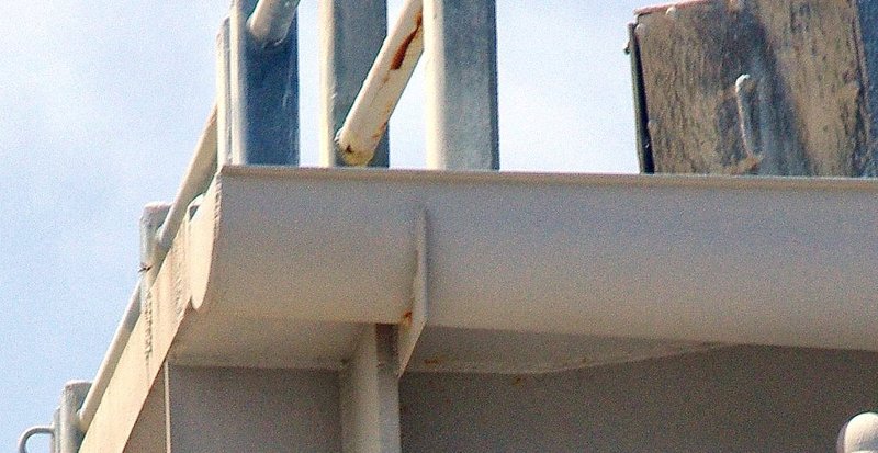
The gutters have indeed the same diameter (10’') over the side length of the MLPs, but their height in the first and last bay strangely diminishes outwards as you can see in this image, if one knows it, otherwise it is not striking. ![]()
But on the linked HiRes image one can see it more clearly, if one follows the alignments of the gutter.
In the Bay 18 I then took measurements, and as you can see, the height difference is about 0,5 mm, which is not much, but at least. 
And then still to the gutter supports, which are fixed on the girders, as can be seen in this picture. ![]()
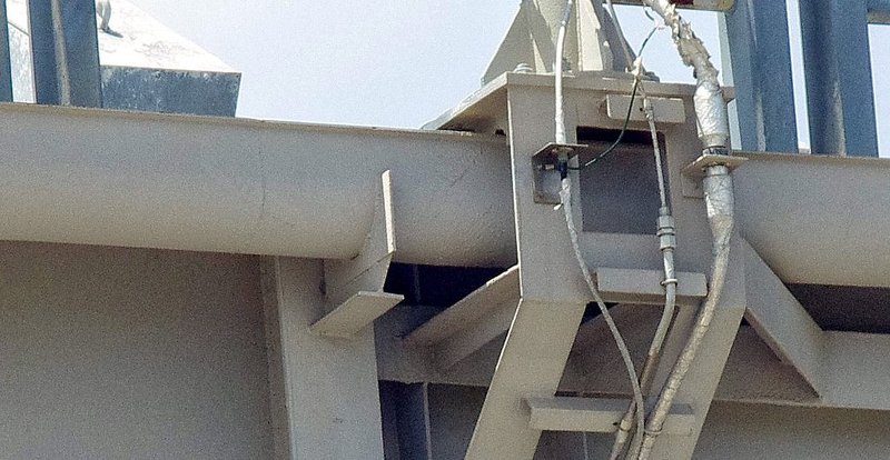
Merely the outer supports at the sides end differ in shape as one can see in these images, at which the lower flange is missing. ![]()
Therewith everything should be clear now for scratching the gutters. ![]()
![]()
6 Likes
I’m still trying to figure out the significance of the stiletto heels ![]()
![]()
![]()
2 Likes
Probably a red herring to see who’s playing attention. ![]()
![]()
3 Likes
Can’t beat a swanky pair of Louboutins lol…
2 Likes
Sorry guys, don’t know wht you referring to. ![]()
![]()
4 Likes