Space Shuttle Launch Complex 39A with Challenger STS-6 (1:144)

Hello everybody,

the last few days there was still a nice surprise, because the featherweight package of Shapeways( with the AFTCs has arrived, cool1

and was very carefully unpacked, after all, it’s my first, but certainly not my last. https://www.britmodeller.com/forums/uploads/emoticons/default_fraidnot.gif

The Thanksgiving card made me even more curious. https://images.raumfahrer.net/up035091.gif

At the first glance, everything was packed very well.

At first I was surprised by the number of bags , especially since I had ordered both versions, FUD and FXD, so four rings. https://forum.raumfahrer.net/Smileys/yabb/huh.gif

But that’s it for today, see you later, and stay curious my friends …

2 Likes

Nice updates. I think the problem with things like silvered or alloy parts is over time they naturally dull, so its tricky to find a happy medium ??

1 Like

Thanks John, :worthy:

let’s wait and see.

1 Like

Hi friends,

and here are the 3D printed AFTSs, where one can hardly distinguish the two kinds with the naked eye, to the left the FUDs, and to the right the FXDs.

Of course, they now have to be freed from the rest of the supporting wax necessary for printing before they come fully into their own.

Only at higher magnification one can recognize the dividing lines between the individual segments, whereby the surface of the finer-grained structure of the FXD (right) feels a bit finer.

But of the feared and often described stepped structure of 3D prints is no trace, which has pleasantly surprised me.

And as one can see, the ring fits perfectly in the SRB Aft Skirt,

as well as the nozzle into the ring, which proves that I must have measured well and the parts have been printed exactly.

And so I really like the 3D AFTC Ring much more better than the spartan part of the Airfix Kit, to whom the Revell ASTC comes relatively close.

I suspect that the dividing lines between the segments become even more visible after cleaning and can still be seen after painting, so that the silver foil insulation strips can still be glued on well.

6 Likes

looks fantastic

1 Like

Hello everybody,

quickly a small addendum to the ASTCs, which are tailor-made for the Airfix Shuttle Stack (1/144).

But one can use them also for the Revell Stack, as one can see on this image.

Since the inner diameter of the Revell Aft Skirts is slightly larger than for Airfix, it might therefore be advisable to glue an Evergreen Strip 0,25 mm x 1,0 mm around the ASTC ring. Then the ring would probably fit even better.

Or I could ask my ARC friend and 3D modeler Joe (crackerjazz) if he could enlarge the ASTC rings for the Revel Kit to Ø 33,5 mm. https://www.britmodeller.com/forums/public/style_emoticons/default/hmmm.gif

And finally, the still remaining test with the Bare-Metal Foil (New Improved Chrome), of which still 24 thin strips (1 mm) must be glued after the painting of the rings, for what a lot of patience should be necessary again.

For this I have cut a longer 1 mm wide strip. Then the very thin film can be easily removed from the carrier strip, then each short pieces of it were cut off,

and glued to the half tube (to the left of the green line) as well as onto the Airfix ring and pressed and smoothed with a Q-Tip. These are the two stripes to the right of the Liquid Chrome strip that I have recently applied with the Pumpmarker.

And as one can see, the Bare-Metal Foil is sticking firmly even still after some hours. Let’s see what it tomorrow will look like, hopefully not as with some of the previous stripes, but rather still unchanged firm, wherefore I precautionally press both thumbs. https://images.raumfahrer.net/up050224.gif

And the chrome luster of the stripes is in my opinion completely sufficient, so that I would be fully satisfied with this result, if it stayed so.

3 Likes

Hello everybody,

and even after a day, the strips are still gluing unchangedly in place, so that the decision for the Bare-Metal Foil (New Improved Chrome) has fallen.

Then I wanted to see how the stripes on the ASTC would look like, and was pleasantly surprised again.

Cutting these approx. 7 mm long and 1 mm wide strips and gluing over the dividing lines between the segments, however, proved to be the expected delicate matter, because one has hellishly to take care when handling with cutter and/or tweezers, so that the very thin foil does not tear off.

And as one can see, the dividing lines under the stripes are becoming slightly visible, but the same can also be seen on this photo from the STS-43 at a higher magnification.


Source: flickr.com (NASA on The Commons)

All in all, a completely successful matter with these 3D-ASTCs, which was worth all the effort.

4 Likes

Hello friends,

I am pleasantly surprised myself by the quality of the AFTCs, which shows that Shapeways is on a good way.

I can recommend you the parts with a clear conscience.

And also after two days, the state of the Bare-Metal Foil stripes is unchanged stable,

and looks very well.

3 Likes

Hello everybody,

after having been more intensively involved with the AFTC rings that have been printed meanwhile by Shapeways and tested by me, I want to go back to the 3D modeling of the ET ntertank wherewith Michael Key had started some time ago, what I’ve been posting about. cool1

Therefor I had sent him in the result of my research my drawing and the estimated Stringer dimensions without and with foam insulation, where actually only the dimensions with foam insulation for his 3D modeling are relevant.

Thereupon he had to adjust his 3D model once again, which I as a 3D rookie have not imaginated so complicated, but which should turn out to be a fallacy. https://forum.raumfahrer.net/Smileys/yabb/rolleyes.gif

Meanwhile he told me that he has modeled another version with these stringer dimensions, given by me,


Source: Michael Key

consisting of each 26 Stringers in the two Thrust Panels and of each 40 Stringers in the intervening Stringer Panels.

But somehow I immediately stumbled over his number of 40, that’s totally 80 stringers in the Stringer panels, which I was very surprised because I dimly remembered a number 108 in our German Raumcon discussions, wherewith the confusion around numbers and terms started at the beginning of my project start (11/2011).

After intensive researches I finally found the explanation in the System Definition Handbook SLWT, in which the Intertank structure is described quite well.


Source: Space Shuttle/External Tank System Definition Handbook SLWT

After that one has to distinguish the following terms:

While in the six Skin/Stringer Panels (45°) there are each 18 of these Stringers,

one speaks in the two Thrust Panels of Ribs, whereby in each case 26 parallel ribs as well as 7 circumferential ribs are integrated in these panels.

Therewith was clarified at least the number of stringers 108, which showed that Michael Key’s 3D model had with totally only 80 too little stringers. https://forum.raumfahrer.net/Smileys/yabb/rolleyes.gif

And now I had to explaine this fact heavy-heartedly Michael Key, whereby I was afraid that he would lynch me for it. https://images.raumfahrer.net/up037692.gif

Thereupon he was very disappointed and had initially thrown in the towel quite frustrated.

But of course, I did not want to give up that fast … https://www.britmodeller.com/forums/uploads/emoticons/default_fraidnot.gif

On the other hand, it would probably have been more useful to distribute the Stringer number onto the circumference of the eight 45° panels, whose drawing he had also been given by me. But in hindsight one is always smarter than before … https://forum.raumfahrer.net/Smileys/yabb/rolleyes.gif

In the meantime, I did it my way both for the six Stringer Panels and for the two Thrust Panels with following results and sent it to him, in the hope that he would have an insight as well as a good will. https://forum.raumfahrer.net/Smileys/yabb/huh.gif

Long story short, therewith I obviously had affected his honor, so that he was ready to go on. But I had to confirm to him that it would finally remain, in each case 54 stringers in the Stringer panels (135°) and in each case 26 ribs in the two Thrust panels (45°), whereupon I gave him my word and was jolly glad.

2 Likes

Hi. I would like to add my two cents worth on the ET. Note that the inter tank (IT) geometry varies with time. You have already noted how geometry varies around the circumference in order to spread and support the point loads of the solid rocket boosters (SRB). If you choose a single external tank number you will see variations as production continued. I was supporting production from the third ET through mid 1989. My time at Michoud in New Orleans East included the Challenger event and recovery with the Rogers Commission investigations.

My background is mechanical engineering. I worked in Jon Dutton’s Stress Analysis group at Michoud from 1982 to 1989 right at the end of the Standard Weight (Heavy) External Tank and the start of Light Weight Design Tanks. I got there as ET #3 was flown. These were all the 2219 Aluminum tanks. The Super Light Weight Tank designs started production after I had moved on to other things. My focus at Michoud was mostly weld geometry, and evaluation of buckling of shell design. My work on the intertank was more limited, but I have been inside one during production support. I saw the machined portion of the ET intertank connection with the SRB recovered after the 51-L Challenger failure of the O-ring.

I find your level of detailed modeling for the launch pad and the water gutter system amazing. Much more intensity than I could muster. I only hope that your the treatment of the External tank would at least reach the level of knowing which tank to focus on. ET-8 (LWT-1) These are not mass produced drop tanks, but the ET forms the load carrying structure from the SRBs to the Orbiter. Sorry for all my attitude, but it comes from a love and admiration for your work. I can commit to digging out the earlier equivalent System Definition Handbook LWT, in which the Intertank structure is described if that would be useful? All the best

Thanks Stuart for your great contribution, :worthy: so to speak, between fellow mechanical engineers. My specific background about 40 years ago was Materials research. cool1

Interesting to hear that they worked at the Michoud Assembly Facility (MAF) in New Orleans. I looked at tons of images there back then, especially when it came to specific details of the ETs. up0455181

Then you’re of course familiar to images like this one from MAF showing some LWTs 5, 6 & 7.


Source: wikimedia.org

The first Lightweight External Tank (ET-8) was used in the STS-6 mission, I’m modeling.

I’m familiar with the System Definition Handbook SLWT, so it would be very interesting if you could find the LWT Handbook for me.

3 Likes

Another nice update and its great seeing and hearing people with all this in depth knowledge from hands on experience. Must have been amazing working and being part of the Shuttle program.

1 Like

Thank you Manfred for sharing your modeling skills with us! I have really enjoyed seeing your work. Glad if I could share a little something that may support your efforts.

I am attaching some preview here of what I have. When I can figure out a proper method to scan pages, I would like to send more on the Thermal Protection System (TPS) dimensions. Sorry for the large dump here, but I can send more in a private message as needed if you’d like.

All the best.

3 Likes

Sorry but I must add another comment about your photo of LWT 5, 6, and 7 lined up in the assembly area.
This photo shows how Lockheed Martin (at that time Martin Marietta) production was gearing up to support 40 flights per year. I think at the time of the Challenger 51L event, our company was about the only contractor reaching that production rate. The pressure to fly like an airline included Kenneth P. Timmons, vice president and general manager of the Michoud division, on a regular basis walking out on the floor of 103 to personally monitor hardware status. Imagine our surprise on January 28, 1986, when the production rate changed from 40 tanks (to zero for the next two years) to 6 flights per year. The Michoud Assembly Facility was parking External Tanks in every covered area available.

Thanks John for your nice words. :worthy:

That’s right, in that spirit, let’s keep the memory of NASA’s Shuttle program alive.

2 Likes

Thanks Stuart for your help and support, :worthy: I could have needed this information back when I built my ET that time, which will be seen later.

1 Like

Hello everybody,

there are progresses to be reported of Michael Key’s intertank modeling.

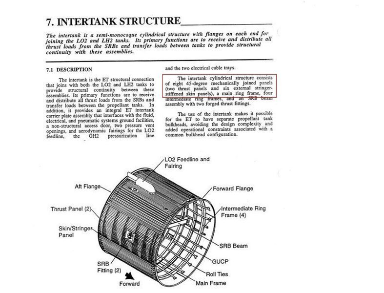
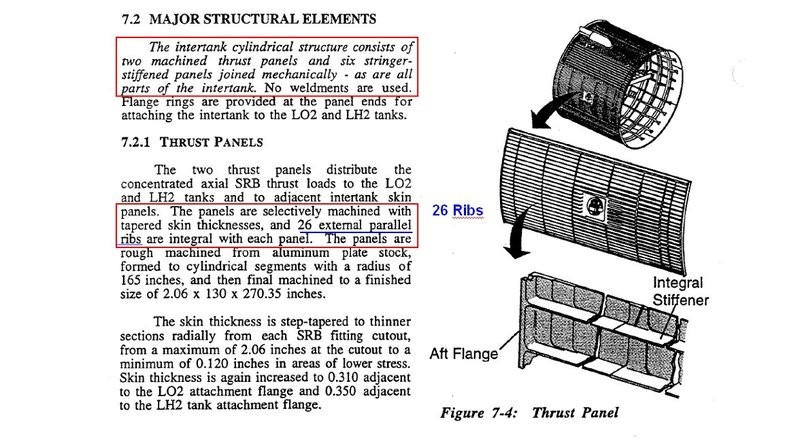
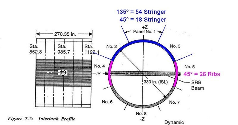
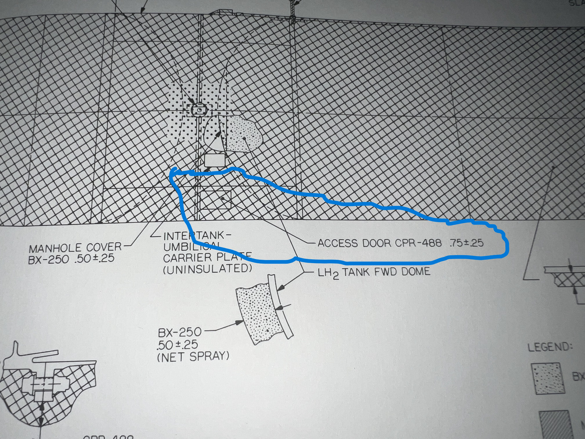
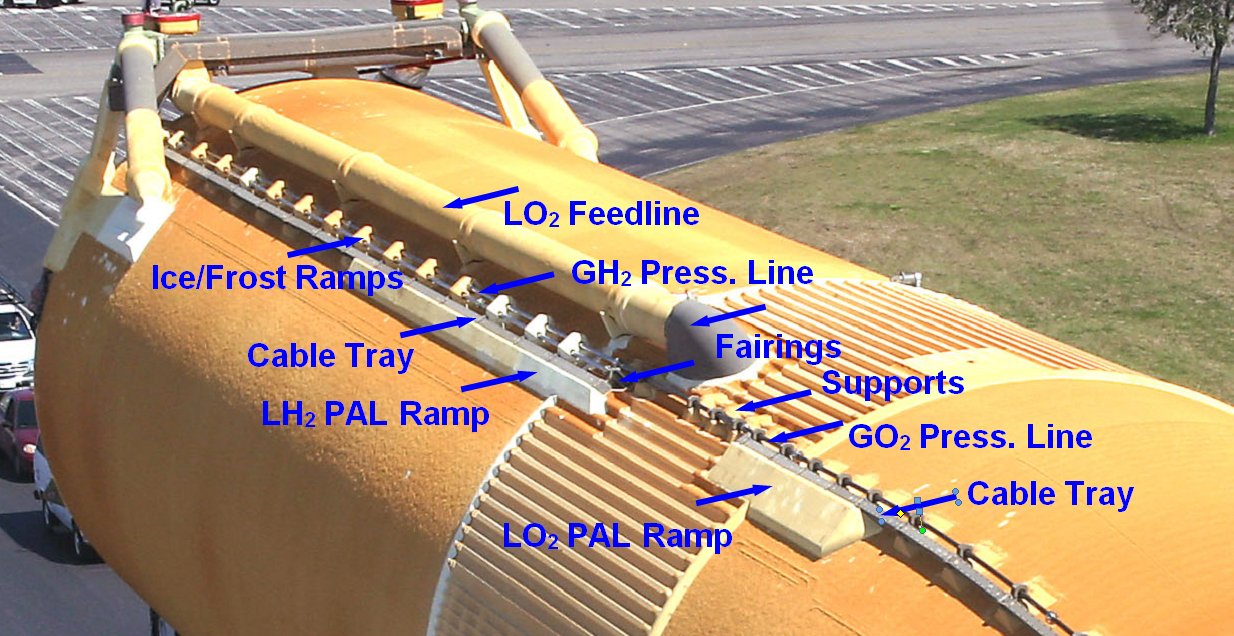
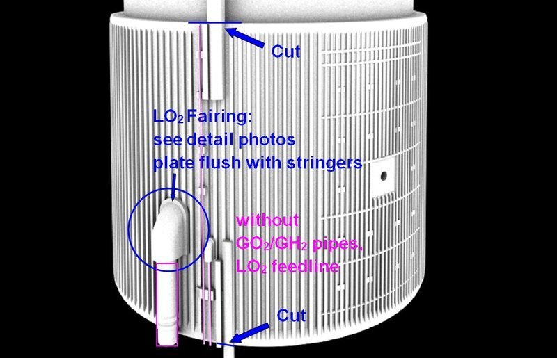
After the number of Stringers (108) and that of the Ribs (52) have been clarified, we now have to clarify some further details on the Intertank, which are marked in this image, some of which have already been integrated into Michael’s model.


Source: NASA

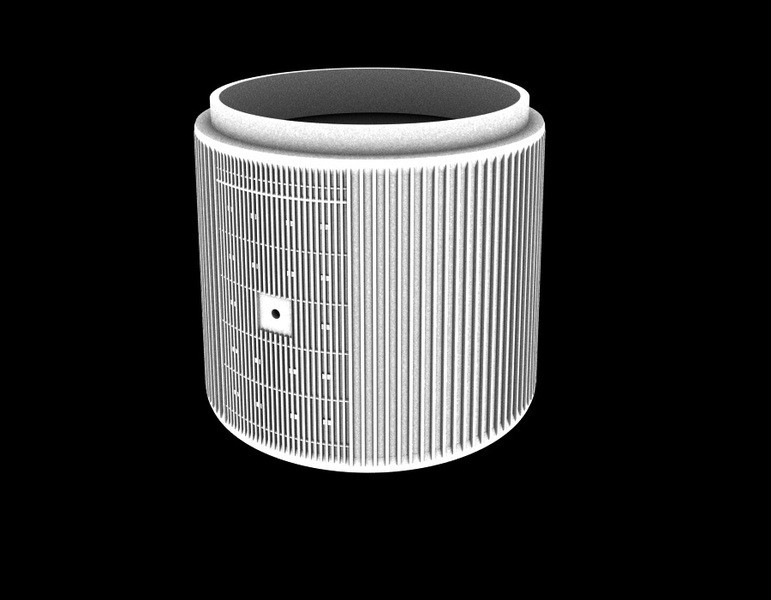
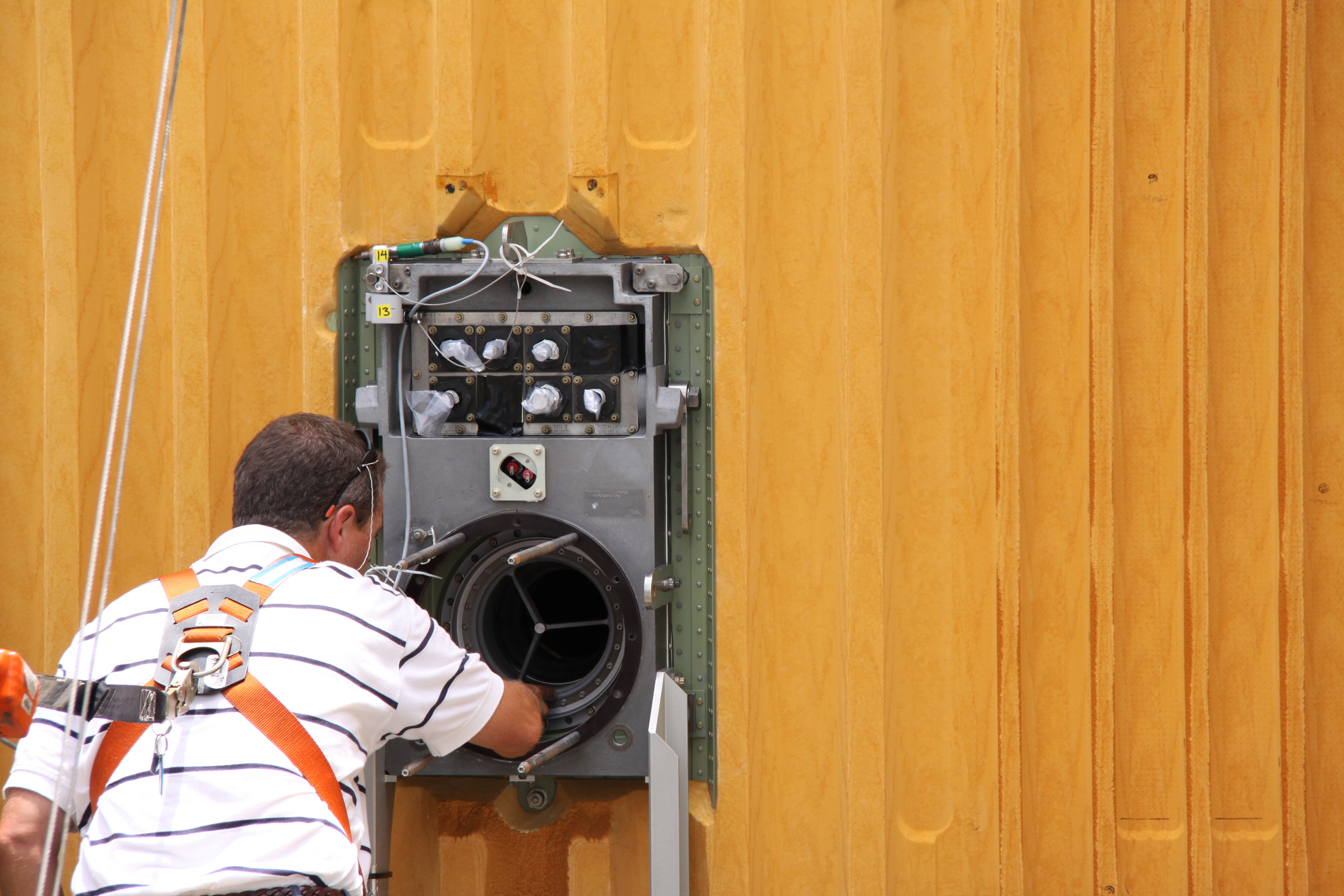
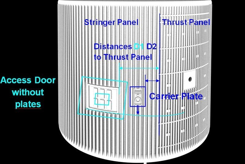
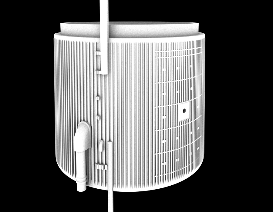
Here are his latest 3D images, whereby I wondered at first about these six plates in the Access Door, that I’ve never seen before.

Furthermore, I noticed that the size and location of the Access Door (AD) and the Carrier Plate (CP) cannot be quite right,


Source: shapeways.com/forum (Michael Key)

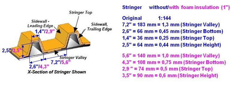
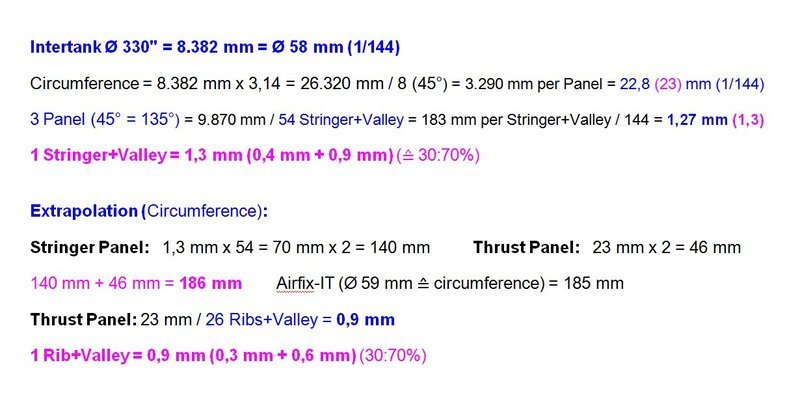
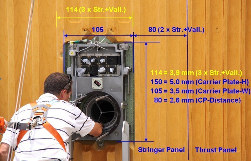
which is why I determined them more precisely based on photos, wherefore I used the agreed reference size 1 Stringer+Valley = 1,3 mm.

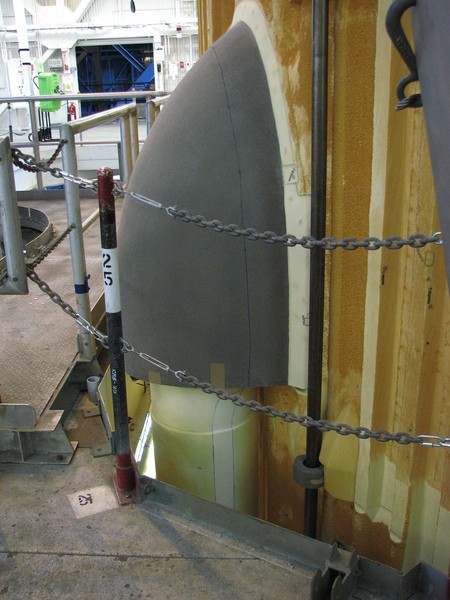
At first I used this great direct view of the Carrier Plate, which has almost no perspective distortions, what should be considered. cool1

For the determination and conversion of the measures, the following explanation of my numbers in the photos with and without mm is necessary, so that one does not get confused.

Numbers without mm are measured values in the respective photo, and Numbers with mm are the converted measurements in 1/144 scale.

And if one compares this photo with his model, stands out that the distance D2 of the Carrier Plate from the Thrust Panel is too large because it should be only 2 Stringer+Valley = 2,6 mm.


Source: NASA

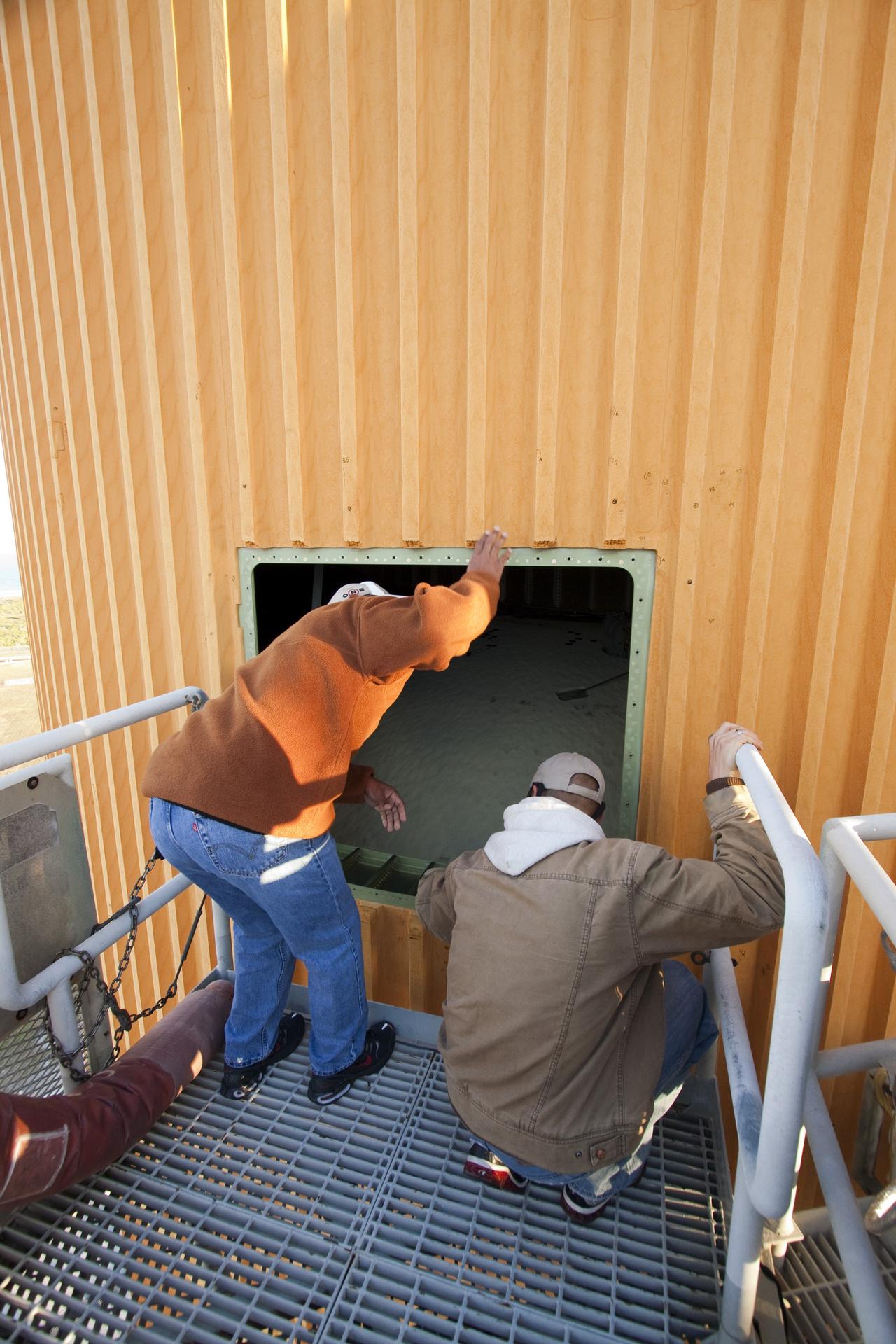
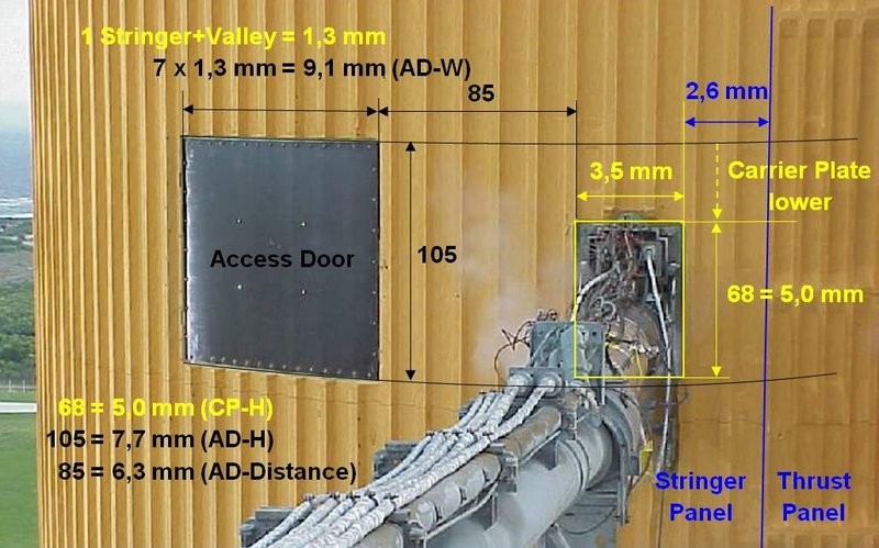
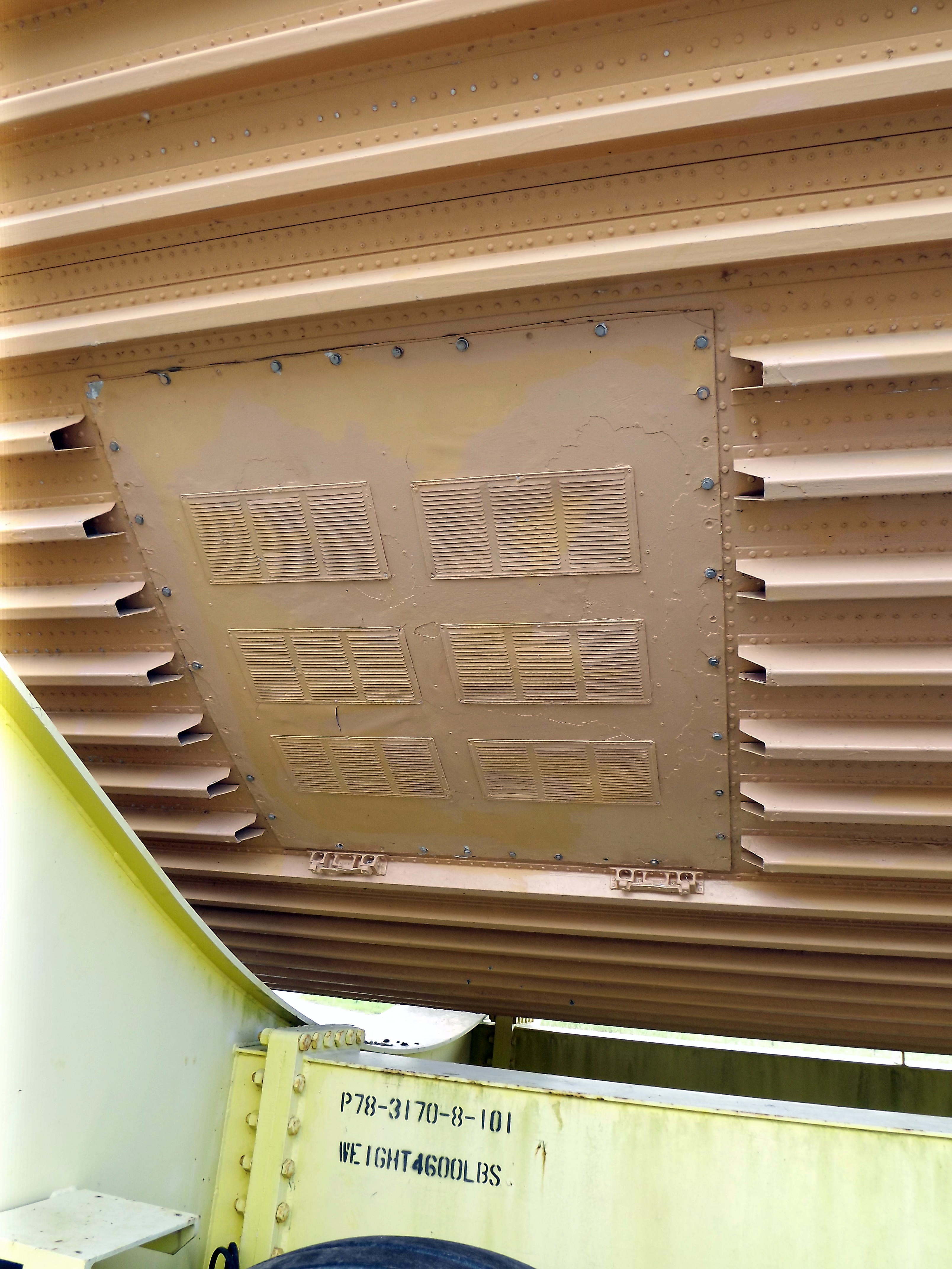
With this distance and the determined dimensions of the Carrier Plate of 3,5 mm x 5,0 mm (W x H) I am afterwards in this photo of the Access Door boarded, which unfortunately is not so distortion-free in the area of the door. https://forum.raumfahrer.net/Smileys/yabb/rolleyes.gif

And in this photo one can see that the door is flat and has no attached panels.


Source: NASA

Here’s a similar image at which the access door panel is removed, which is attached with 44 flat profile screws.


Source: NASA

Thus, the Access Door and the Carrier Plate would have the following dimensions:

Access Door: 9,1 mm x 7,7 mm (W x H)

Carrier Plate: 3,5 mm x 5,0 mm (W x H)

As one can see in the following image, the Fairings of the LO2 Feedline (17’') and of the GH2 Press. Line (2’') were added, as well as the LH2 PAL Ramp and the LO2 PAL Ramp, as well as the Supports for the two Press. Lines and the associated Cable Trays.

Thereto Michael has suggested to omit the two thin Press. Lines and the Cable Trays, as they would go beyond the intertank anyway and could possibly break off during printing or transport.

He was worried about the PAL Ramps. While the LO2 PAL Ramp could survive at the top, he fears that the LH2 PAL Ramp could probably break because it’s very long and thin. So he asked if he should cut them off at the ends of the Intertank, which I did agree with.

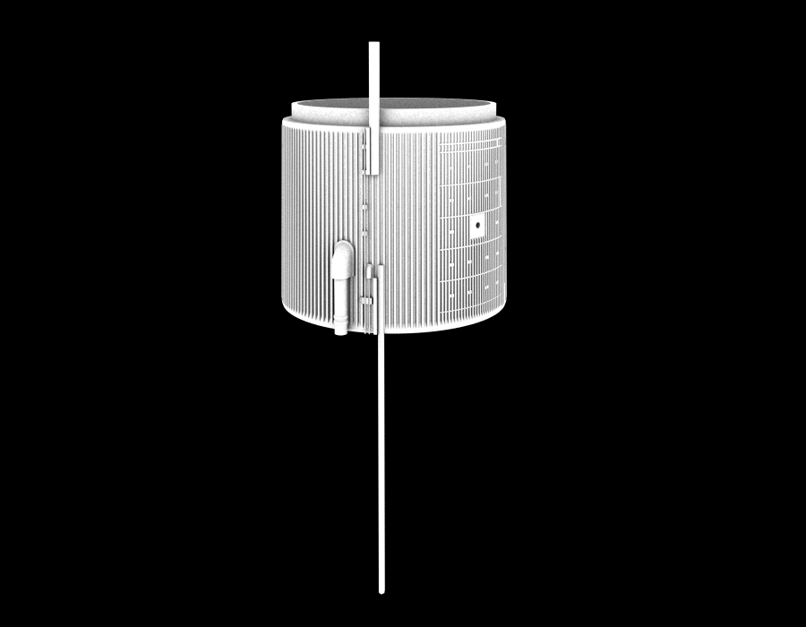
Since I anyway wanted to insert the LO2 Feedline and the Press. Lines, he should omit them away, but not the Cable Trays, because I could continue them to the front and backwards.

Then I still showed him these two photos, on which one can see that the bottom plates of the Fairings are flush with the stringers and not put onto, what he has accepted and wanted to change.
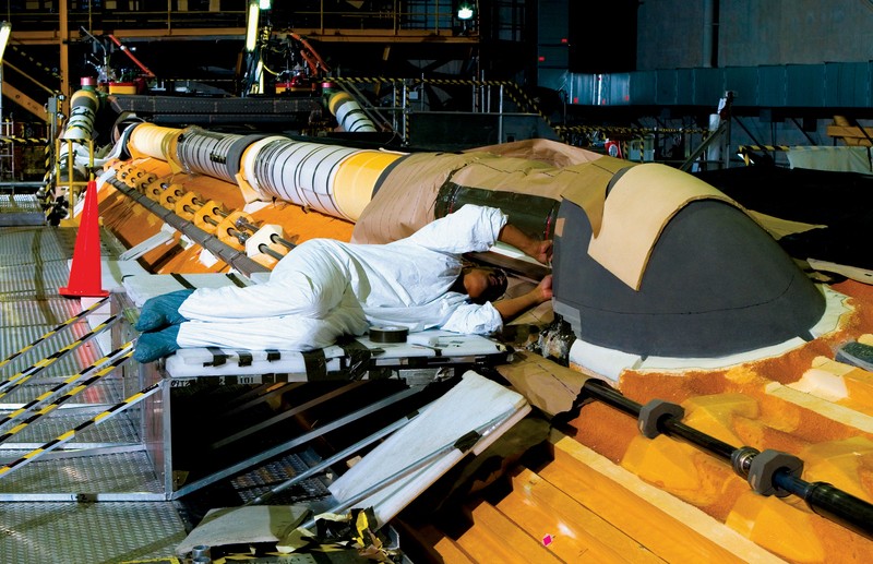

Source: NASA


Source: NASA

These were essentially my hints and correction wishes.

Regarding of his plates attached on the Access Door, which I had queried, he sent me this photo here, which surprised me, since I did not have seen it yet.

That’s why I asked him if he had any source, whereby it could possibly be a Mock-up. https://www.britmodeller.com/forums/public/style_emoticons/default/hmmm.gif

I believe that shows once again that a timely and consensual coordination of such details is important for a smooth process, that’s why one never stops learning.

3 Likes

Hi Manfred. My read of your access door is this is a photo prior to final TPS close out. A lot of things like the tank manhole covers were opened and reclosed at the Cape after shipping from Michoud. The LWT call out I found was .75” plus or minus .25” of Spray On Foam Insulation (SOFI) here. Reference below. I have also included a photo of a hunk of foam to show the as sprayed rough surface. Sometimes as needed on the launch pad small repairs using the “Great Stuff” spray cans were used to fix small issues like woodpecker bird damage. This surface could be smoothed as needed to meet the thickness.

3 Likes

Thanks Stuart for these interesting TPS details regarding the Spray On Foam Insulation (SOFI). :worthy:

Here is another photo of a LWT in final assembly at MAF I’ve found in my database.

BTW, a good friend of mine, Scott “Shuttleman” Phillips, gave me this piece of SOFI foam some time ago. It was used in the construction of the last External tank (ET-138), for the final Atlantis mission (STS-135), and I’m particularly proud of it.

He also wrote this very interesting book Remove Before Flight together with his wife Dianne Phillips, essentially his memoirs.

Imagine, Scott Phillips also turned a Shuttle model from the SOFI foam that accumulated before the final spraying process of the ET-138. https://images.raumfahrer.net/up037692.gif


Source: Scott G. Phillips

He later had this SOFI Space Shuttle model signed by the last Atlantis crew.


Source: Scott G. Phillips


Source: Scott G. Phillips

And this is my friend Scott with one of his over 400 turned Shuttle models made from different types of wood, before Atlantis’ final launch from Launch Pad 39A.


Source: Scott G. Phillips

And this might be of special interest for my follower Stuart (amoz02t), because this Shuttle model was built for Jon Dutton, cause he worked in Jon Dutton’s Stress Analysis group at Michoud in the 90s as he mentioned in his post.


Source: Scott G. Phillips

With these memories of the good old Shuttle days I’m at the end for today.

3 Likes

Thank you Manfred for sharing this! As you say good memories especially today on Mardi Gras! (For us in New Orleans, Fat Tuesday was a day off of work). My memories of Jon Dutton at Michoud in the 1980’s include talking together usually with Dennis Deel, Gale Copeland, and Paul Watkins while sitting on an old couch Jon kept in his office . They all were always very nice willing to help new engineers like me try new things. So much knowledge carried over from folks that moved their families from Denver, CO to New Orleans. I am impressed with the items from Scott Phillips. Like your own work, Manfred, these efforts will help promote the memory of the Shuttle program. I look forward to seeing more. Thank you so much. - All the best - Stuart

2 Likes