Hello everybody,
the 3D model of my friend Joe’s AFTC ring was almost on the way to the Shapeways printers, but what’s the name of it? Things never turn out the way you expect. ![]()
And that had once again to do with the selection of reference photos, where one should not be intoxicated only by the details of great Hi-Res photos, because also the respective time window of such photos may not be disregarded, if one wants to build a specific mission. ![]()
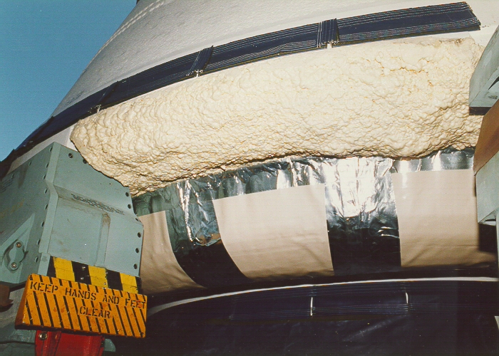
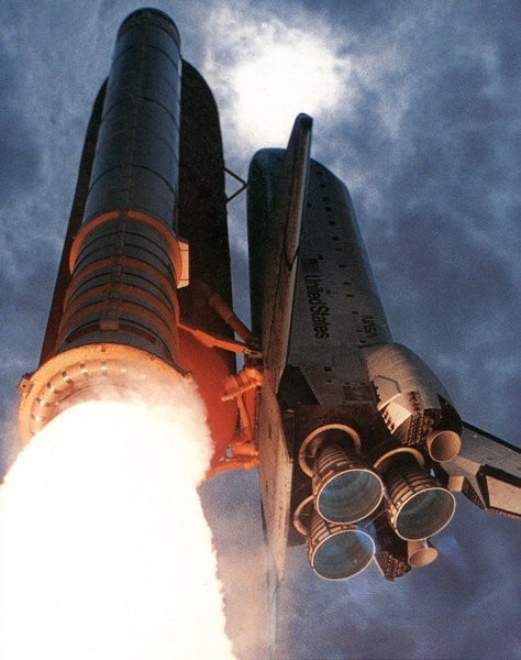
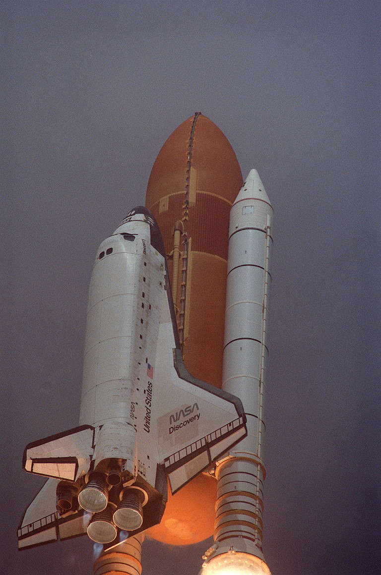
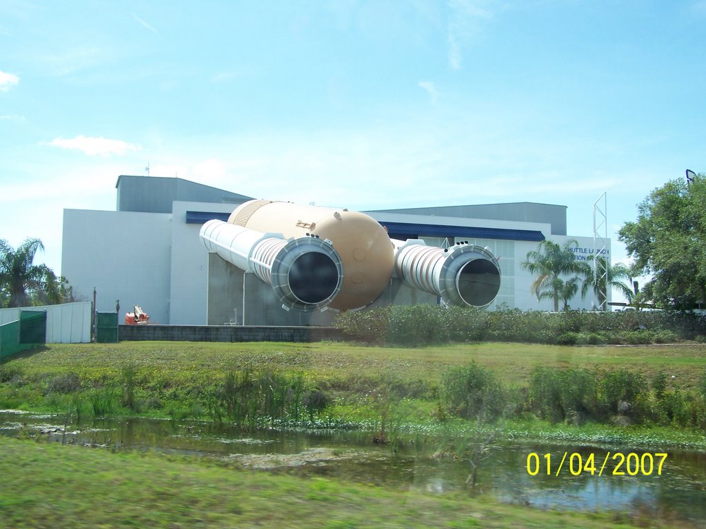
That’s what happened to me with the last photos of the AFTCs, such like this one, which comes from the STS-121 (2006) and thus from a rather late mission,
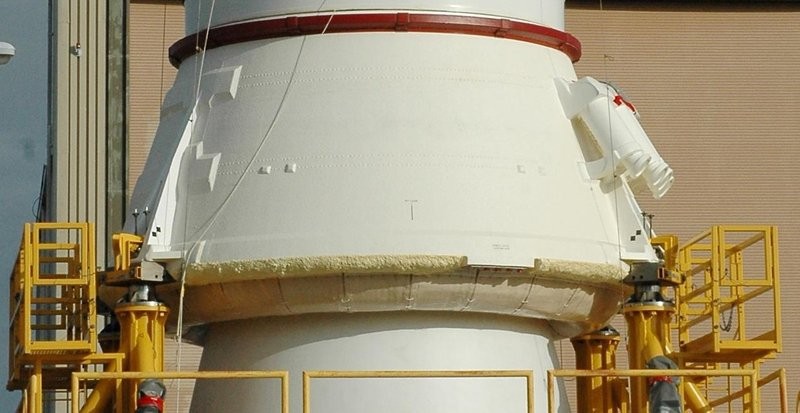
what inevitably raises the question of whether the Aft Skirts of the boosters at the time of STS-6 have looked similar, or possibly different? ![]()
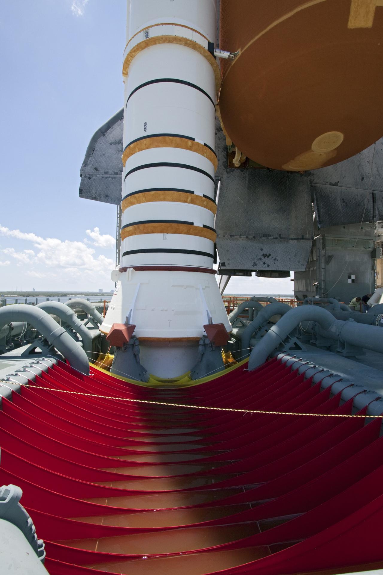
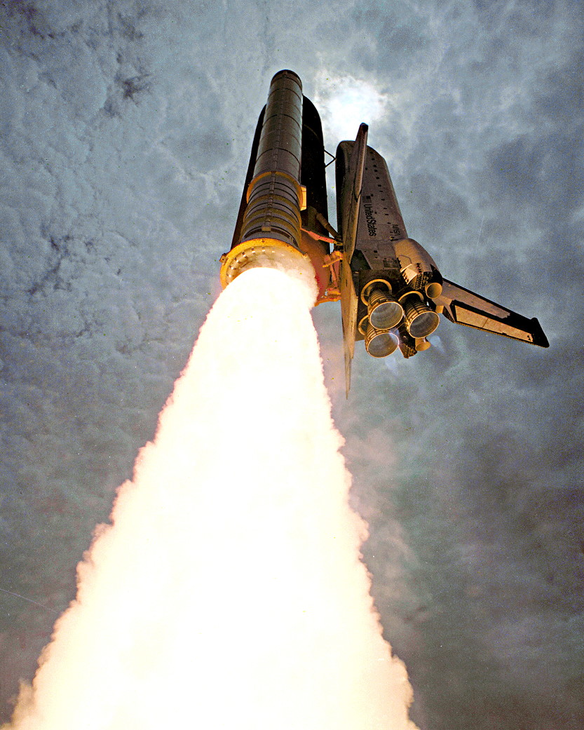
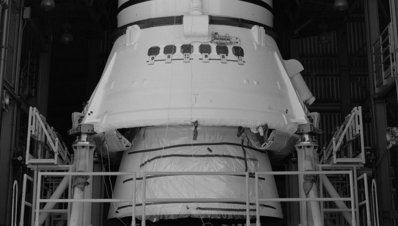
Since I was not able to find any photos that belong to the STS-6 yet, I again searched the Hi-Res archives of NSF Forums (L2) and were very surprised when I have come across this great shot in the thread STS-1: Hi Res Images.
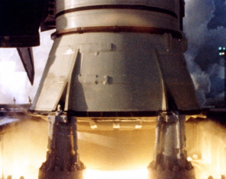
Source: forum.nasaspaceflight.com (heng44)
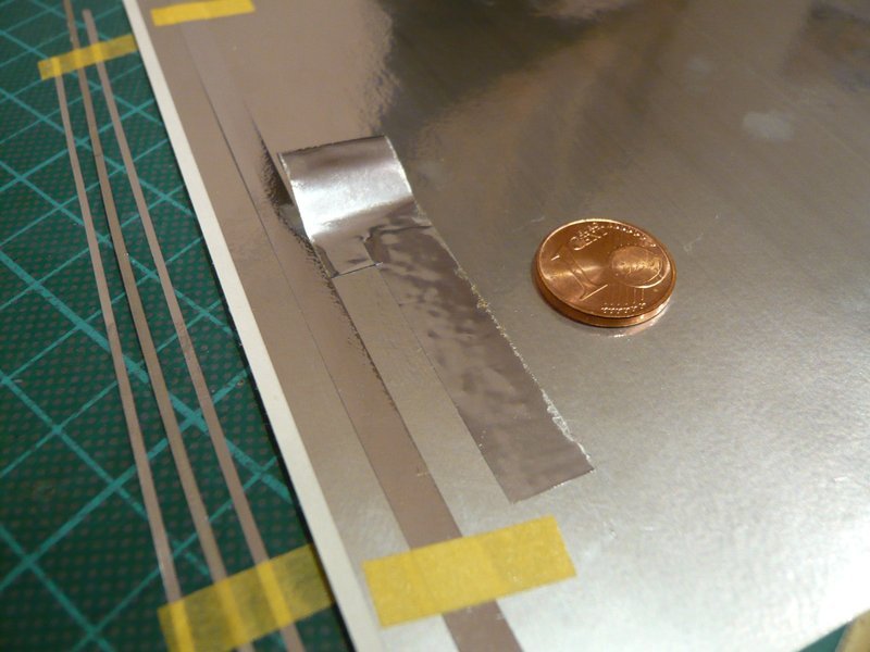
The conspicuous thing about it are the silver stripes between the ASTC segments, which immediately have reminded me of the SRB Mock-ups on the KSC grounds, ![]()
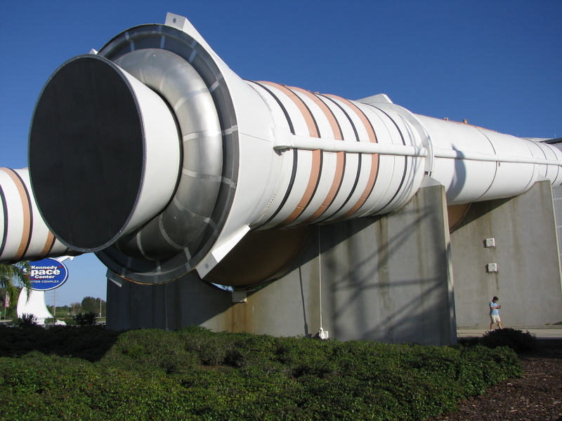
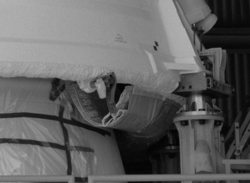
but they only have 16 segments, as one can see here.
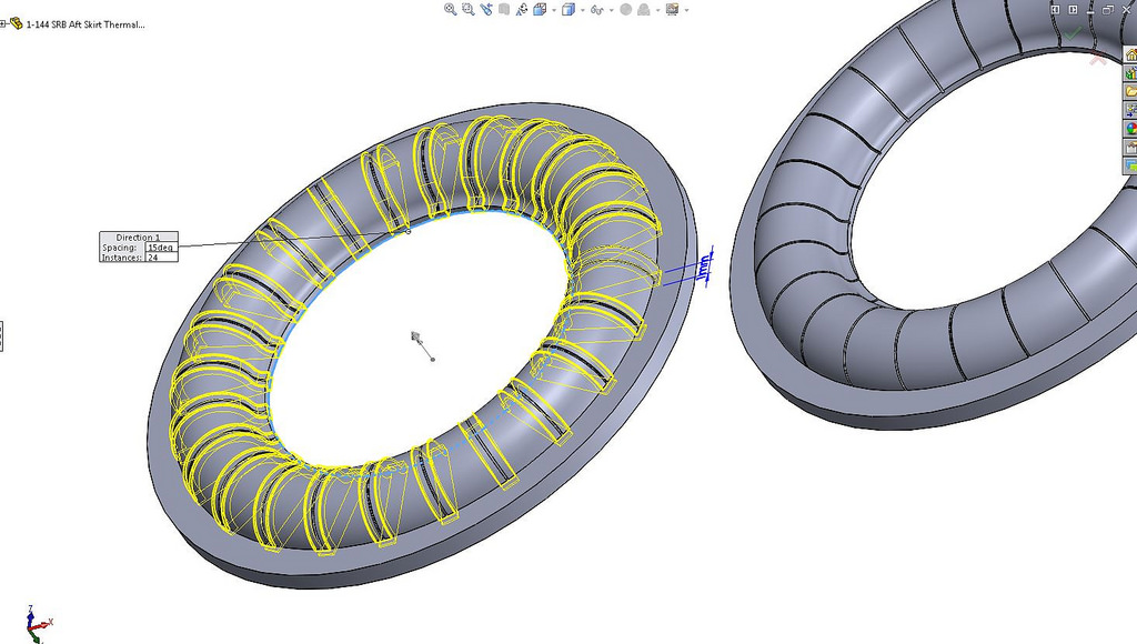
However, as you can see on the STS-1 photo, there were four segments between the two SRB supports, giving a total of 24 segments, whereas the older Mock-ups had only two, what could be a simplified design with only 16 segments. ![]()
Therefore, I assume that the ASTCs in the STS-6 also consisted of 24 segments each, as in the STS-1 two years ago.
At this later photo (2013) of the Mok-ups in front of the entrance to the Atlantis Exhibition Hall on the KSC Visitor Complex there should also be 26 segments, which are covered with stripes at the seams.
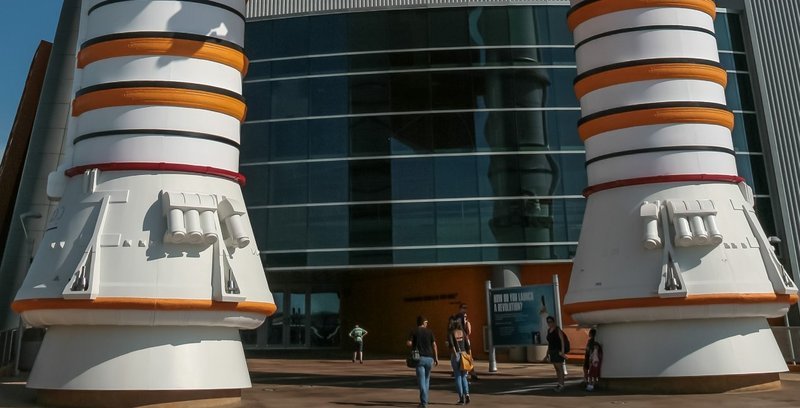
Source: forum.nasaspaceflight.com (Lee Jay)
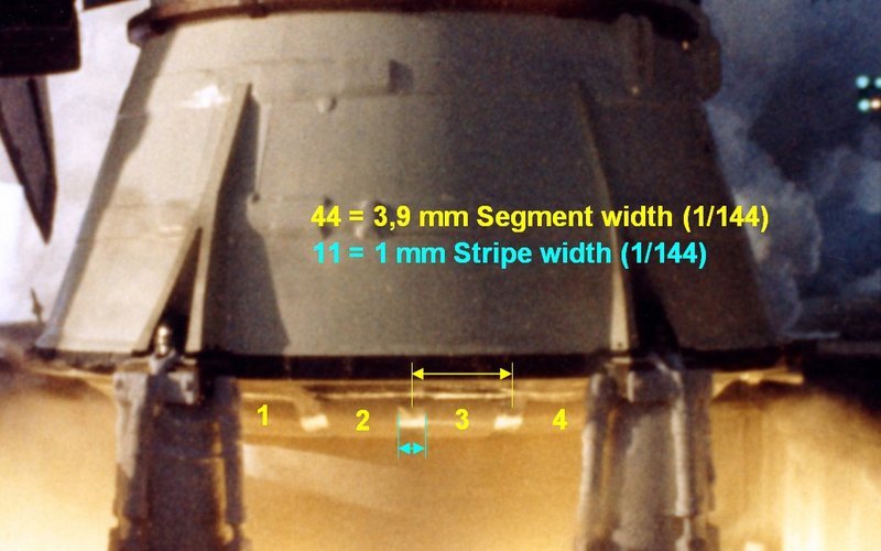
But ultimately, what matters is the ASTC configuration that was present at the launch of the Shuttle stack at the mission, therefore for me the image of the STS-1 is crucial for further 3D modeling. ![]()
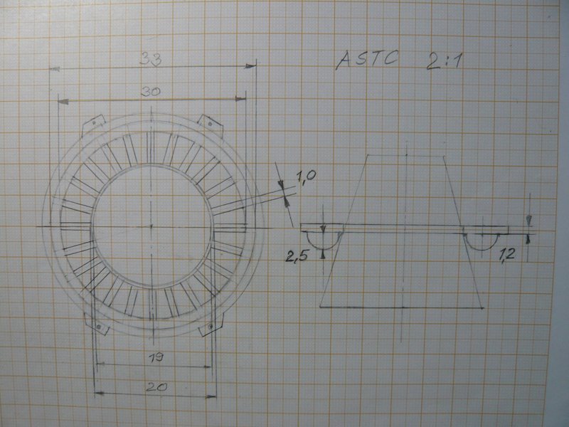
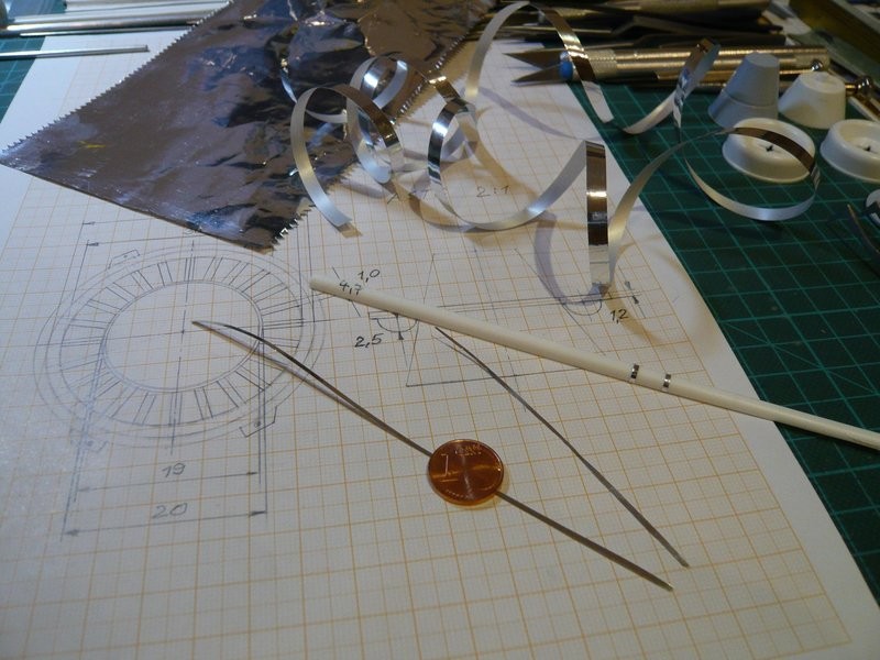
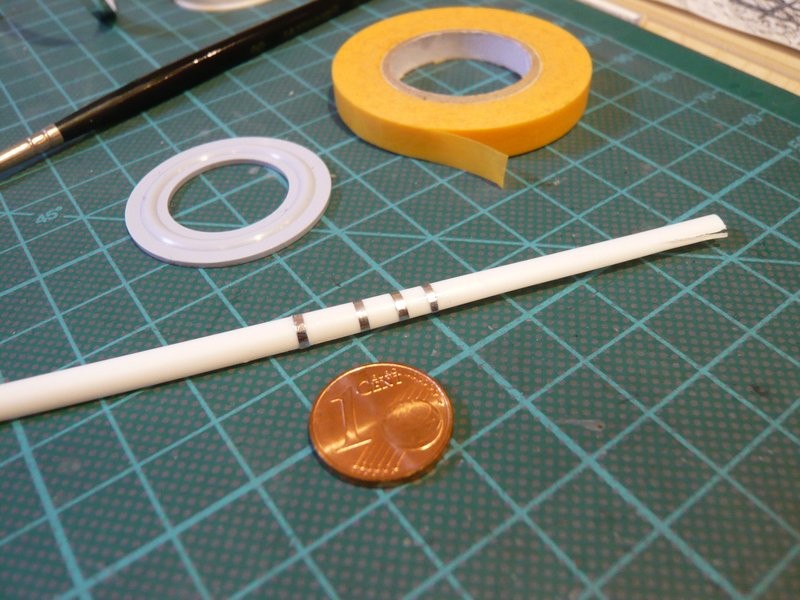
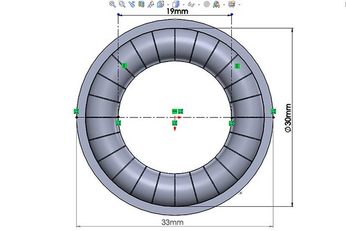
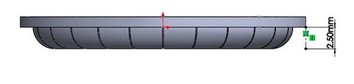
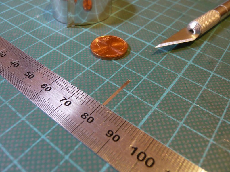
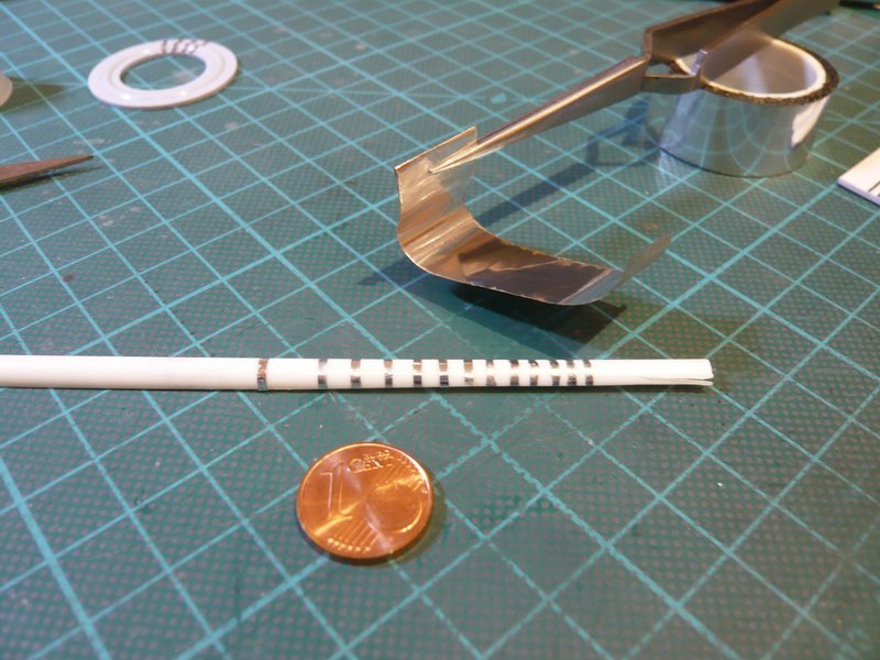
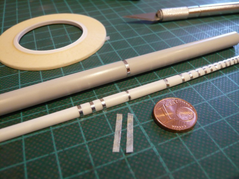
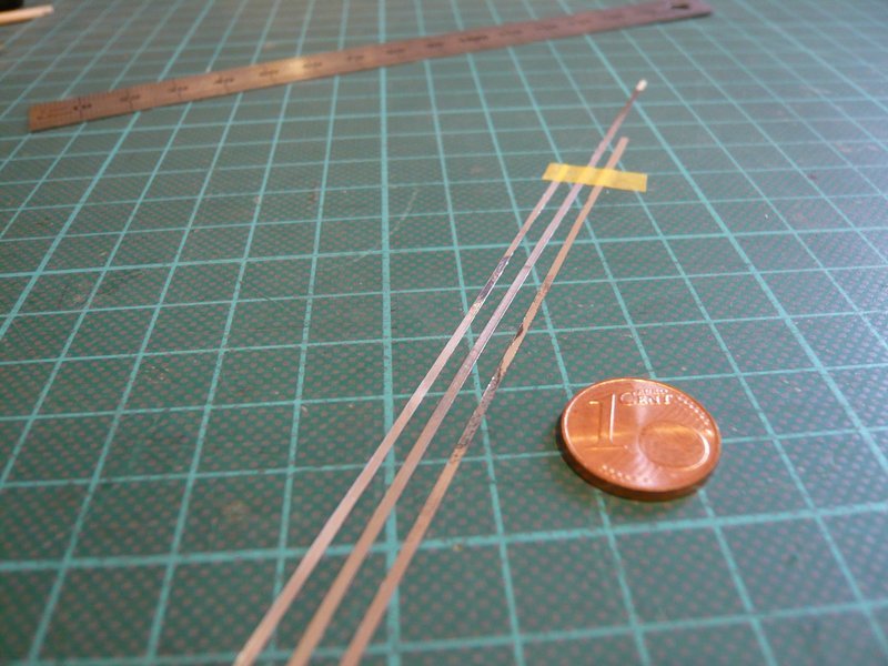
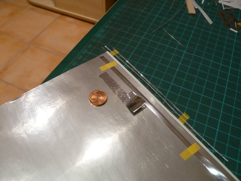
By now I have already instructed my friend Joe, so now he only needs the modified Stripe width, which can be determined from the Segment width, resulting from the circumference of the AFTC ring (Ø 30 mm) with
C = 30 mm x 3,14 = 94 mm / 24 = 3,9 mm
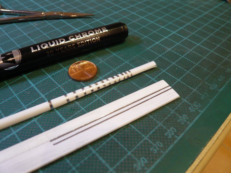
With this Segment width as the reference value, the STS-1 image results in a width of the stripes of 1 mm above the seams between the segments in the 3D model.
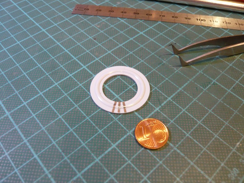
And so I’ve changed my previous sketch, which now looks like this.
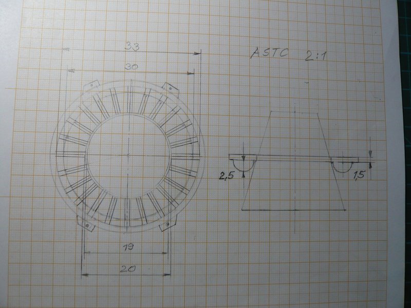
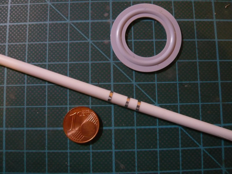
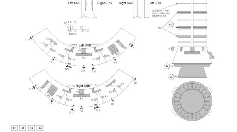
That agrees well with the resin parts in the Newware Space Shuttle Enhancement Kit 1/144 (NW131), as one can see from the drawing in the construction manual, wherefore this kit seems to me to be really worthwhile. ![]()
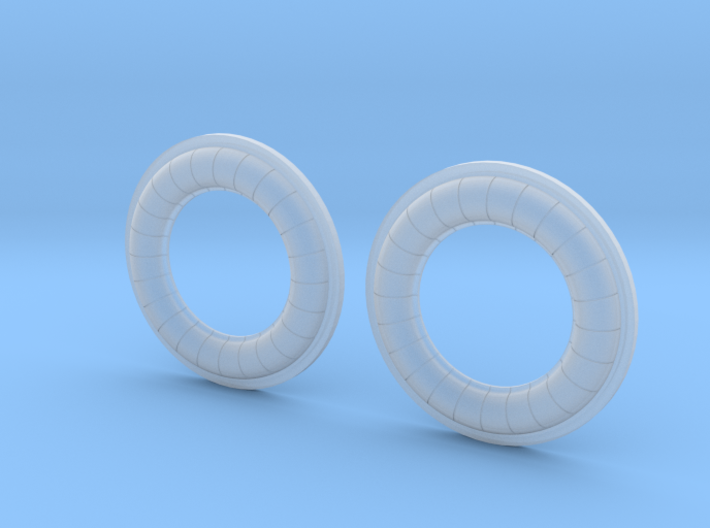
So my friend Joe can now customize his 3D model and upload it soon to Shapeways. ![]()
![]()