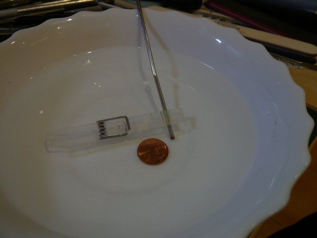
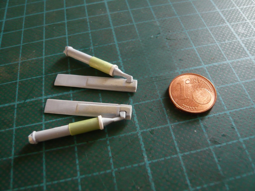
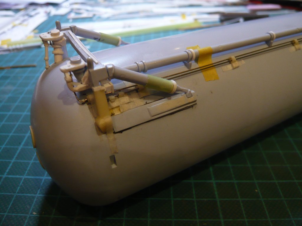
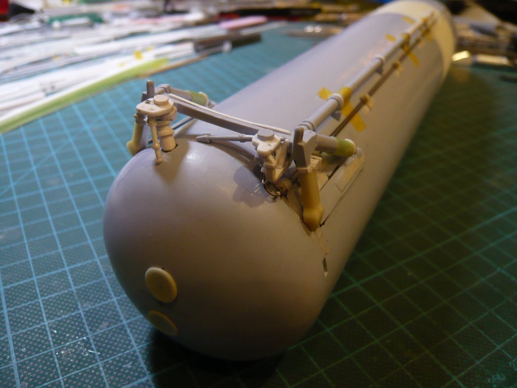
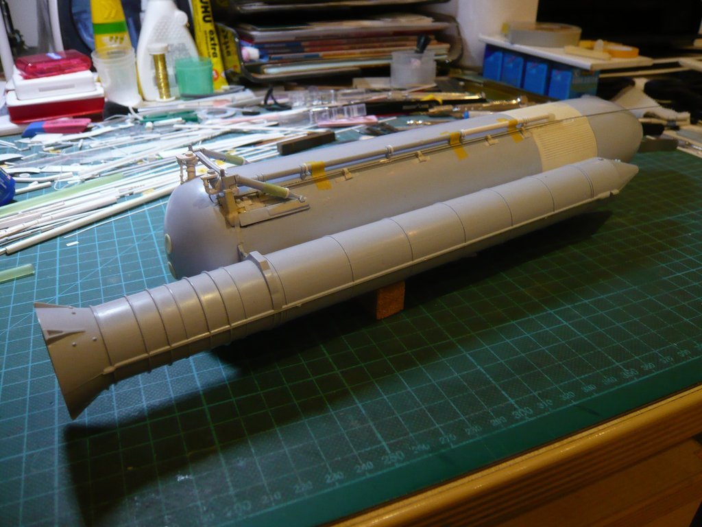
Space Shuttle Launch Complex 39A with Challenger STS-6 (1:144)

Hello everyboy,

unfortunately, in the photos one cannot recognize the course of the GH2 Press. Line so good like that of the GO2 Press. Line, which is why I could not measure the length of the slant up to the lower two bendings directly. https://forum.raumfahrer.net/Smileys/yabb/rolleyes.gif

Therefore, after putting the Attachment on the ET, I could only mark the distance to the first bending after a painstaking threading of the dummy across the LO2 Feedline and through the opening of the small Support in front of the TPS Cladding, what a stressful fiddling was.

Then I’ve tried to get made the two bendings with the round tongs in the smallest spaces, especially since their distances are minimal, as can be seen from this image.


Source: georgesrockets.com (George Gassaway)

And that’s how the bended Copper dummy looked like,

which one can see here in the provisionally installed state.

But somehow the shape and size of the lower bows did not agree, which were a bit too big, https://images.raumfahrer.net/up037692.gif

because, as one can see on this image, the upper bending in front of the slant is much closer to the GO2 Press. Liner. https://forum.raumfahrer.net/Smileys/yabb/huh.gif


Source: NASA

After this first impression, I’ve immediately took the Steel wire (Ø 0,4 mm) and bent it, but it is much harder and more resistant and therefore more difficult to bend, especially in the lower part of the double bendings, which is why several trials and test fittings were necessary. https://images.raumfahrer.net/up035091.gif

At that it turned out that one can perform the lower two bendings only halfway accurate, if one leaves at the lower end first a longer end piece in order to be able to bend at all, and this only then shortens accordingly afterwards.

Threading the line was only possible directly at the Attachment,

whereupon it could be put then onto the ET, in order to try then to insert the lower end into the rear Ice Frost Ramp (R24), but what was not successful instantly, because sometimes either the inclination of the slant or its length was not right, or the distances of the lower two bendings, or all together, what was enough to drive you up the wall …

Therefore I’ll show you the (preliminary) final result after the umpteenth attempt,

which was then satisfactory.

This was followed by (only) still the exercise with the threading of the two Fittings, whereby the action at the lower end still before the threading of the Press. Line under the Crossbeam was comparatively harmless.

But then came the critical place in the circled gap, for what the line in front of the support had to be fixed with a mini-tape strip (arrow) in order not to constantly slip out again. https://images.raumfahrer.net/up037692.gif

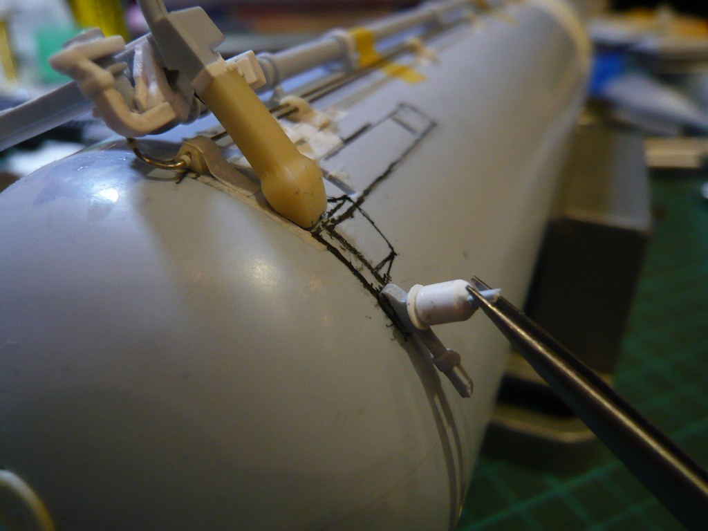
And then I’ve channeled the Fitting ring, which was hanging at the Toothpick-Tape-holder again, into the gap, and carefully inserted the line with the sharpest tweezers, what then sometime has worked again …

But even to photograph these details, some pull-ups and appropriate mountings were needed to get close enough into a suitable position with the digicam,

in which the autofocus (with self-timer) could still focus, as one can see here. https://forum.raumfahrer.net/Smileys/yabb/huh.gif

All in all, a rather time-consuming business with the scratching of such tiny details, whereby the joy is even all the greater when it has succeeded in the end.

6 Likes

Love the way how you make plastic take shape. All these added pipes and amount of detail is phenomenal. I cannot wait to see the final results, with paint and weathering, as I will be lost for hours…just looking at everything and imagining this is a model and not a real thing. :astonished_face:

1 Like

Thanks Mike for your sustainable interest in my crazy scratch-building attempts of this tiny stuff. https://www.smiliesuche.de/smileys/lachende/lachende-smilies-0101.gif

The show must go on, stay tuned!

BTW, Breaking News! https://images.raumfahrer.net/up037692.gif

The wait is finally over: two weeks from tomorrow, on November 13, 2026, the doors to the new exhibition hall at the Samuel Oschin Air and Space Center in Los Angeles will open, revealing the third still existing Space Shuttle, Endeavour.

Unfortunately, I’ll have to wait until my next year vacation for my rendezvous with Lady Endeavour.

Hello everybody,

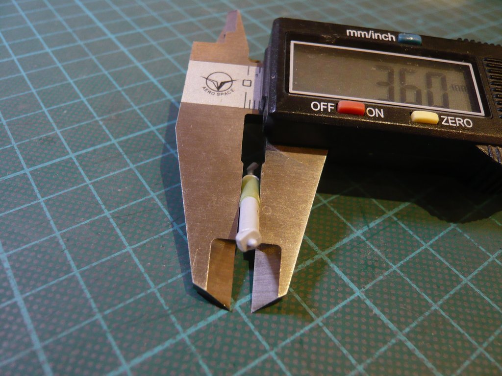
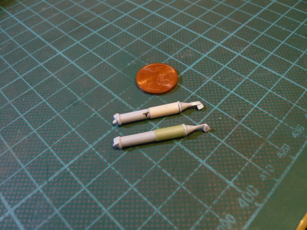
after the two ET/Orbiter Assemblies are now finally completed, there is always still a small line missing, and this is the so-called LH2 Recirculation Line (Ø 4’'), which can be seen here on the ET-45 (STS-47).


Source: georgesrockets.com (George Gassaway)

The line looks relatively simple and has a slight kink at both ends,


Source: forum.nasaspaceflight.com (DaveS)


Source: System Definition Handbook SLWT, Vol. II (Lockheed Martin)

in front of each time a Protective Shroud sits.


Source: System Definition Handbook SLWT, Vol. I (Lockheed Martin)

And so plain and simple looks this part of the Airfix Kit, whereby the two Shrouds are missing, which is not the end of the world. https://forum.raumfahrer.net/Smileys/yabb/rolleyes.gif

First, I’ve tried it again with a Copper dummy (Ø 0,6 mm), and then I’ve tried to drill out a Rod ( Ø 1,2 mm) for the Shrouds stepwise in the center up to Ø 0,7 mm, which is not that easy with this diameter. https://forum.raumfahrer.net/Smileys/yabb/huh.gif

After the temporary installation of the Dummy, which did not cause any problems,

I’ve then bent an Evergreen rod (Ø 0,7 mm) for the final line.

As already mentioned, drilling out can not be made immediately to the final inner diameter (Ø 0,7 mm), because the drill can slip too easily and does not stay in the center, therefore carefully step by step. https://forum.raumfahrer.net/Smileys/yabb/undecided.gif

After that, I’ve cut off small 0,5 mm wide rings and had to find out that the bore had run eccentrically inwards, so unfortunately only the front ring could be used. https://forum.raumfahrer.net/Smileys/yabb/rolleyes.gif

That’s why I then drilled out only still 1 to 2 millimeters and then cut off the ring so as not to produce too much rejects.

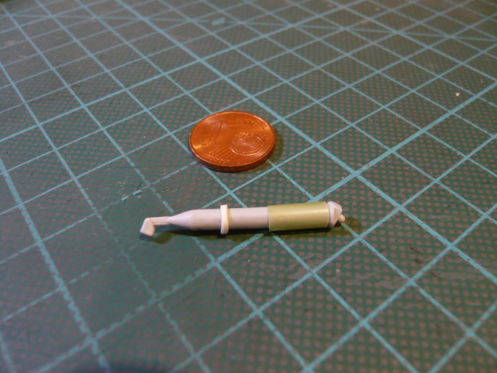
And that’s how I actually managed to make three useable rings,

and to thread them onto the rod, whereby the line looks significantly better than the Airfix cripple.

But when I kept the result of the test fitting in my sight, https://forum.raumfahrer.net/Smileys/yabb/huh.gif I was a little disenchanted, because the line seemed a bit too puny compared to the LH2 Feedline,

what I’ve remembered differently when seeing all the photos … https://forum.raumfahrer.net/Smileys/yabb/huh.gif


Source: NASA

And when I was brooding about it, suddenly it felled from my eyes like scales … https://images.raumfahrer.net/up037692.gif

Out of power of habit of recent weeks in intensive dealing with the GH2/GO2 Press. Lines, whose diameter is 2" (Ø 0,4 mm - 1:144) and which are “naked”, i.e. have no TPS cladding, the diameter of the LH2 Recirculation Line of 4’’ (Ø 0,7 mm), which was used by me as a reference measure, concerns also only the “naked” stainless steel line, but which still has a 1’’ TPS cladding (SS-1171/SLA-561), what results in a diameter of 6’’ (Ø 1,0 mm - 1:144), what I should have taken into account (see right scaling),


Source: georgesrockets.com (George Gassaway)

which is why I’ve then used the corrected dimensions.


Source: capcomespace.net

For the new line with the larger diameter (Ø 1,0 mm) I have then punched small discs (Ø 1,5 mm) for the Shrouds with my Punch & Die Set made of Styrene (1,0 mm),

which I’ve then drilled out in nine steps from Ø 0,5 mm to Ø 1,0 mm and chamfered,

and then threaded onto the new bended line that I like much better now.

Then I’ve drilled out the openings in the Umbilcal Plate as well as in the ET Aft Dome to 1 mm and carefully inserted the line, which now fits much better into the mould,

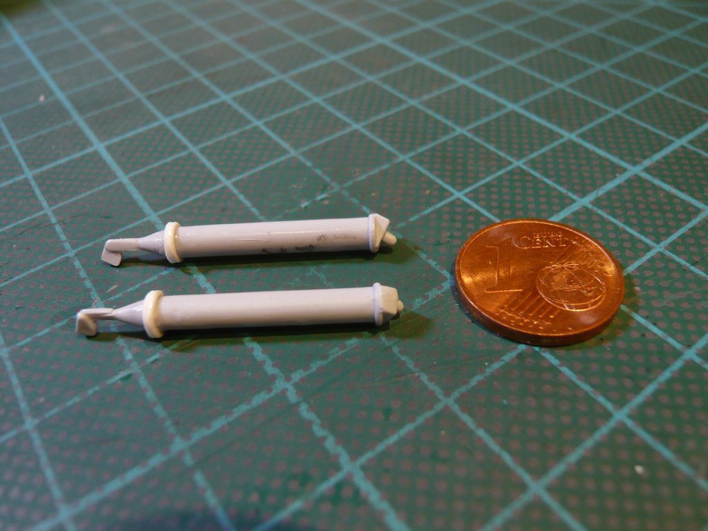
as one can clearly see here in the comparison of both variants.

Just good thing I’ve still noticed this lapse and could correct it,

because with it now I can finally finish this Umbilical chapter.

Now only a small detail is missing on the Crossbeam, which still has this cover with the outer slight slants on the top at the front edge, what it also was always good for …


Source: NASA

This last detail I also still want to scratch now, wherewith then the ET/Orbiter Aft Attachment would be complete in my eyes.

4 Likes

Hello everybody,

from the Britmodeller Forum the question came up, if I forgot the Diagonal Cross Strut which of course is not the case. But for the sake of simplicity, I had not implemented it up to now, but I made up for it right away.

And now to the long and narrow cover on the Crossbeam, for which I first determined the dimensions from this photo of the ET-37 (STS-37).


Source: georgesrockets.com (George Gassaway)

As one can see, this is only a narrow thin strip, which increases slightly obliquely on both sides to the outside, which is not so easy to realize in the range of less than 1 mm in height. https://forum.raumfahrer.net/Smileys/yabb/huh.gif

That’s why I considered to cut a 0,8 mm wide strip (above) from a thin Evergreen Sheet (0,13 mm) and then to glue it together with the two slants, made from an Evergreen Strip (0,4 mm x 0,75 mm).

Since I’ve used again MEK, I also had to underlay Teflon foil, so that nothing could glue on. https://forum.raumfahrer.net/Smileys/yabb/rolleyes.gif

Then I’ve put on the laboriously sanded slants and carefully fixed with the cutter, and then lightly brushed with MEK from both sides, which is sufficient for the gluing.

And so the cover was already as good as finished, only the transitions of the slants and at the ends, I have the strip a little bit smoothened.

Afterwards, I’ve glued this strip similarly with MEK onto the Crossbeam, whereby I’ve glued step by step from one side to the other side.

And as I think, the cover comes out pretty well and it’s nothing to sneeze at.

With this now also this last detail would done.

4 Likes

Hello everybody,

after these details on the Micro level, which were surely stressful for the viewer too, https://forum.raumfahrer.net/Smileys/yabb/rolleyes.gif now again to somewhat larger parts on the ET, which I slowly want to prepare for the SOFI Insulation using the “Flour technique”.

To do this, I first had to recap once again how I wanted to do this with gluing of the ongoing Tape spiral (Barber pole) using the 0,75 mm wide tape strip for simulating the SOFI Pattern Texture.

Regarding this, I had come to the conclusion at the time that it would be easier to mark the adhesive points for all add-on parts, such as the entire ET/Orbiter Aft Attachment incl. Longerons, as well as Ice Ramps and PAL Ramps, etc. and to make recesses for it on the spiral, before the Flouring process, which are then to be covered separately with tape pieces, and only to glue these parts onto the ET after the tank has been floured, primed and painted, and only to paint the add-on parts finally by hand. https://images.raumfahrer.net/up035091.gif

And now step by step to the missing details on the ET.

Among other things there was still to be due the extension of the LO2 Feedline, which is too short in the Airfix Kit, which I found to be easier due to the already existing Bracket rings of the Feedline Support Brackets than replacing the complete Feedline including the application of new rings.

For doing this I’ve thought about cutting the line in front of the “last” ring, which is actually the penultimate ring, because the last Support bracket in front of the Intertank is missing in the kit as is well known. https://forum.raumfahrer.net/Smileys/yabb/rolleyes.gif

The replacement piece of the line (Ø 3 mm) I drilled out at the rear end, which thus can be plugged onto the centering pin (Ø 0,4 mm) in the rear part of the line,

and ends in front flush with the Feedline Fairing on the Intertank.

Then I’ve still glued the front Bracket ring, what for I used an Evergreen Strip (0,4 mm x 0,6 mm), which I had previously bent under hot air around a steel core.

But right next to these narrow Bracket rings there are also somewhat wider rings, of which the front four are missing on the Airfix Feedline, and these are the so-called LO2 Feedline Bellows, which sit in front of the Support Brackets and are numbered green in the following image.


Source: NASA

These Bellows enable the Feedline to be balanced by expansion/contraction both during refueling and during flight.


Source: NASA

The dimensions of these rings I have determined from this image,


Source: NASA

for which I used an Evergreen Strip (0,5 mm x 1 mm), which I wrapped around a steel core and formed into a spiral under hot air,

which has also retained its shape even after cooling.

The diameter of the Core wire (Ø 2,5 mm) I’ve chosen deliberately slightly smaller than that of the Feedline (Ø 3,0 mm), so that the the spiral threaded onto the rest of the feedline fits closely and all I had to do was cutting off the Bellow rings with the razor blade.

I started with the anterior of the four Bellows right in front of the Intertank, in front of which there is still a narrow ring,


Source: NASA

which I’ve then also glued.

And this is what this group looks like on the ET,

and just for the fun of it I’ve have threaded the two Press. Lines, which overall makes a pretty good impression, I think.

Now I can confidently glue the three rear Bellow rings (2-4), which I hope that the spiral will give the rest, wherewith the LO2 Feedline would be done.

6 Likes

Hello friends,

meanwhile the remaining three LO2 Feedline Bellows are now glued too, so that the Feedline is now complete.

Next I’ve set out to pimp the ET Aft Dome a little bit, that is the rear dome-like end of the tank, in whose Aft Dome Cap there are these two Covers as one can see here on the ET-8 (STS-6),


Source: forum.nasaspaceflight.com (Jester)

as well as here on the ET-45 (STS-47).


Source: georgesrockets.com (George Gassaway)

These are the so-called Manholes, of which I did already know the marked Manhole (Ø 36’') from the book “Remove Before Flight”, written by my friend Scott “Shuttleman” Phillips,


Source: Scott Phillips

through which, after the final inspection and acceptance of the ET-1, he was the last person of his team to leave the tank for the STS-1 Mission and even got handed over the red Remove Before Flight Ribbon by the quality inspector, whereupon he was of course very proud of.

From these Manholes there are three exemplars in the Newware Kit made of Resin (R42),

and two as PE parts (P44).

I will use the Resin parts, since their rear is slightly curved, which means that they lie better against the dome.

As one can see from the sketch, the two Manholes are not arranged in the middle, but the exit manhole sits slightly below the middle, the location of which I have marked here on the Aft Dome Cap,

and then both discs were temporarily put onto the dome.

I’ve glued both Manhole covers with Pattex-CA because the normal Revell plastic glue for gluing Resin parts is not suitable.

And with that straight to these lighter Closeouts, which can be seen here on the ET-45 (STS-47), and in a similar form also on all ETs, the meaning and purpose of which was initially unclear to me.


Source: georgesrockets.com (George Gassaway)

But since I like to know what the parts I’m building are actually good for, I first have asked my ET expert, Scott Phillips, and also DaveS, which both had a simple explanation for it, for which I’ve then searched for appropriate photos and also found.

These are the ET’s rear contact surfaces/points on the transporter specially designed for him, which I’ve circled in red in the following image, which can be seen more clearly in the zoom. https://www.smiliesuche.de/smileys/spiegel/spiegel-smilies-0002.gif


Source: NASA

Strictly speaking, these are the so-called ET Aft Support Transportation Fittings for which there was this special device on which the ET was bolted down to the transporter, whereto I’ve found this drawing in the ET Bible.


Source: System Definition Handbook SLWT, Vol. II (Lockheed Martin)

An interesting fact is to note that before each ET’s transport the SOFI foam of these Closeouts had to be removed and then reapplied, which resulted in different shapes and colors of these areas. https://forum.raumfahrer.net/Smileys/yabb/huh.gif

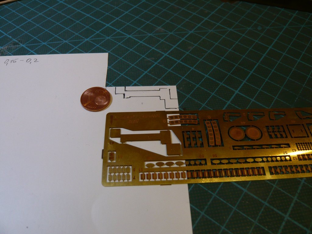
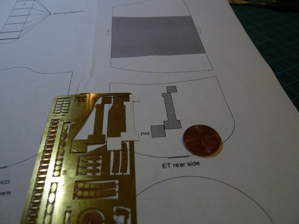
And also for these Closeouts there is a corresponding PE part (P43) in the Newware Kit,

that could already be seen on the right edge of the PE board in this image, with what it should continue soon.

So far for today.

6 Likes

Hello everybody,

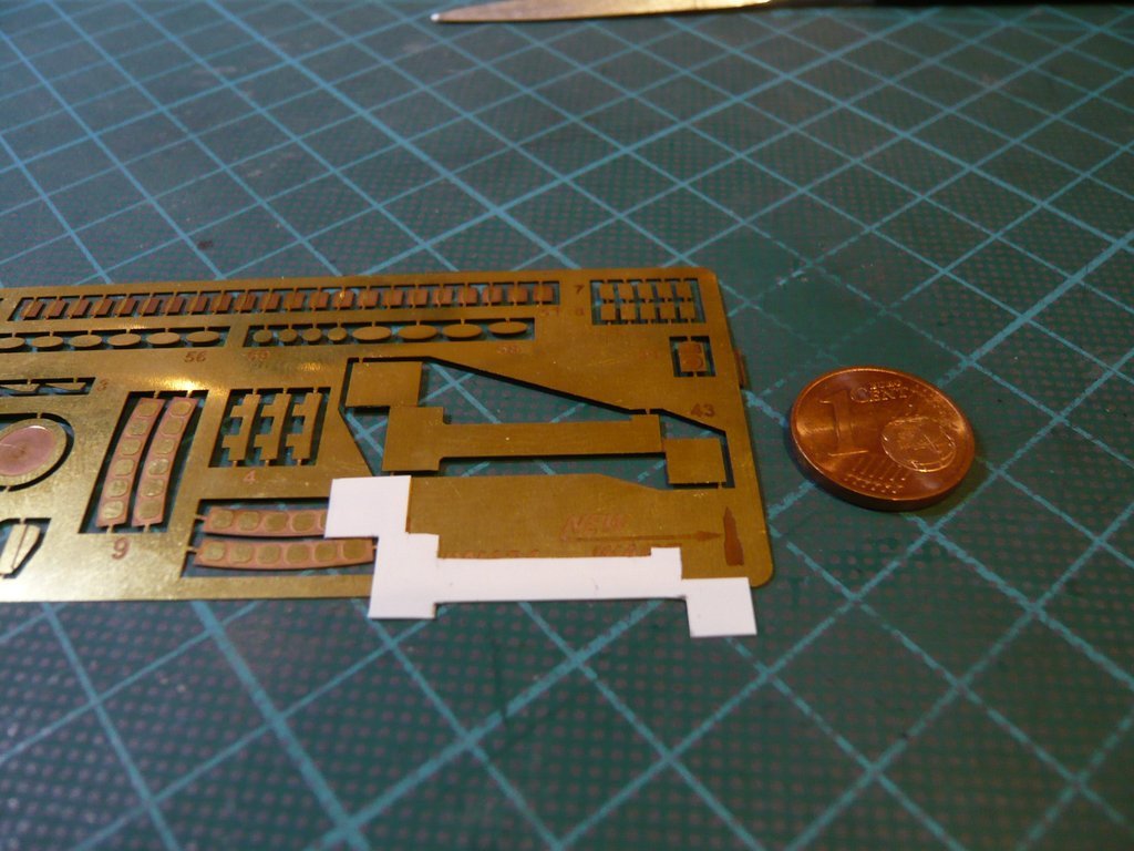
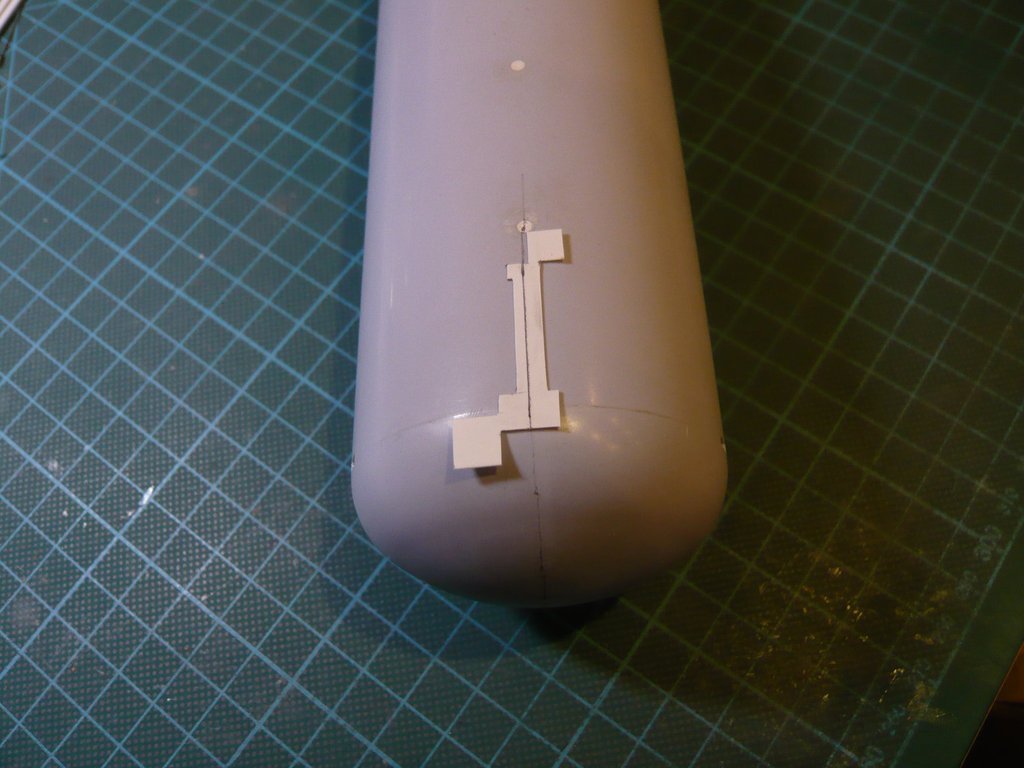
then let’s go on to the Closeouts, which I transferred from the PE board to an Evergreen Styrene Sheet (0,2 mm) because it makes it easier to transfer the contour to the ET.

The part should not be glued for the time being, but only after the SOFI Pattern-Tape-Spiral has been glued on, i.e. immediately before the Flour coating.

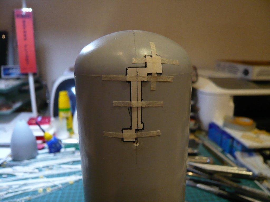
After I had determined the exact position of the Closeouts on the ET,

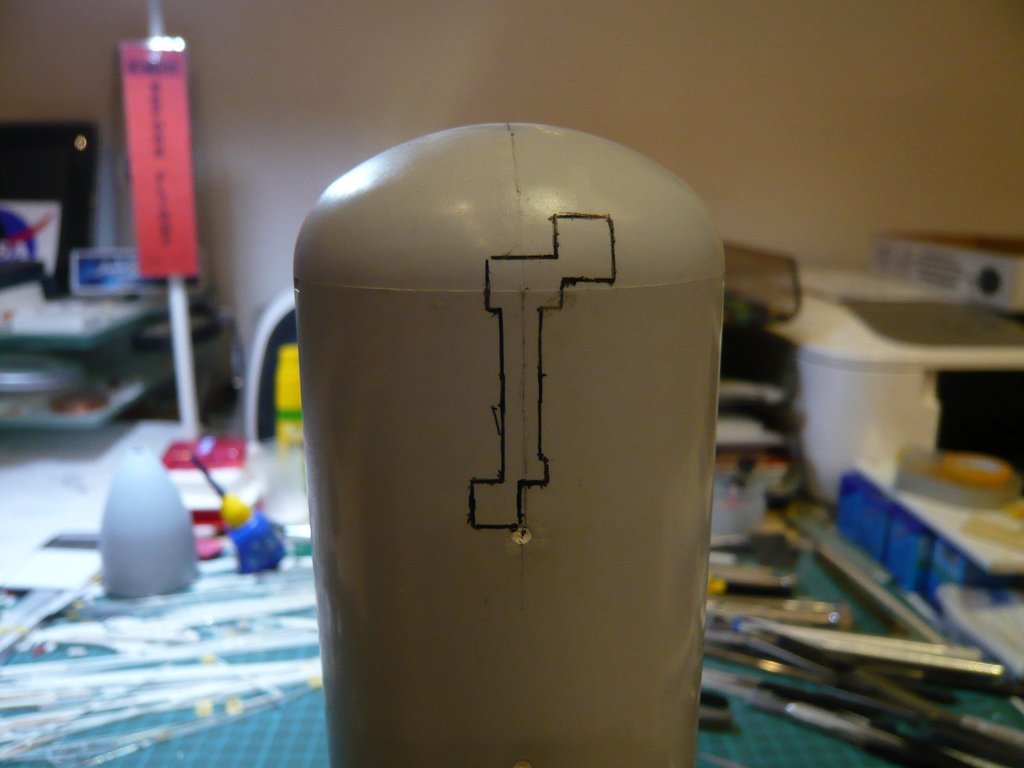
I’ve fixed it with masking tape (2 mm) and was able to trace the contour.

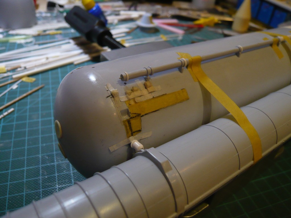
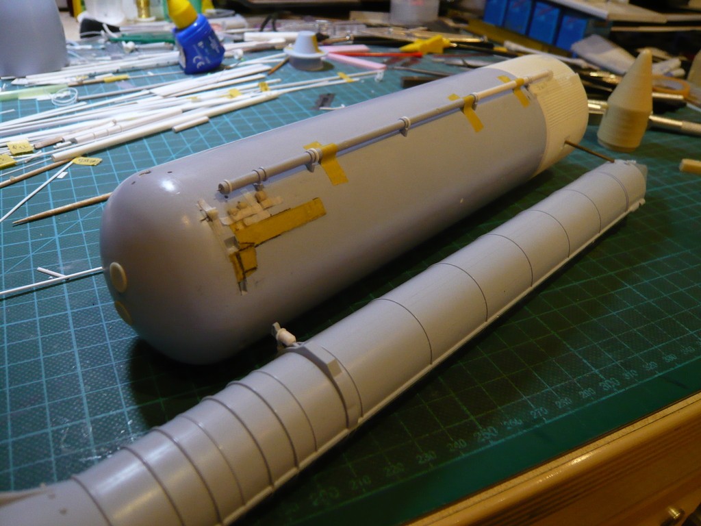
Now I can start soon with gluing on the Tape spiral and then to cut out the contour so that I can subsequently glue on the Closeouts.

And with the two Longerons I will do it same way.

With that I would like to leave it for now.

3 Likes

Hello everybody,

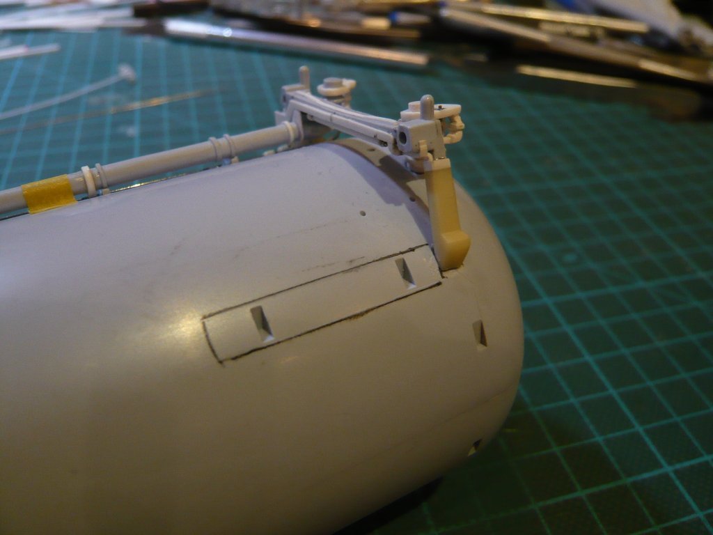
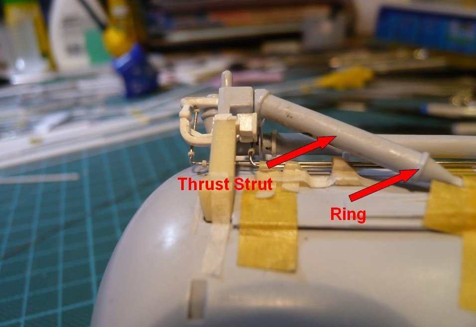
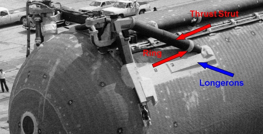
today I want to present you some small details at the Thrust struts and the Longerons, which I still would like to modify because the original items look a bit different than in the Airfix Kit. https://forum.raumfahrer.net/Smileys/yabb/rolleyes.gif

As one can see in this image of the ET-6, the diameter of the Thrust strut in the front part is a little bit larger and the front ring a little wider,


Source: forum.nasaspaceflight.com (Jester)

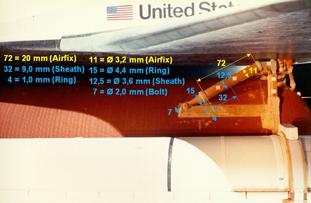
which one can see more clearly in this image of the ET-33 (STS-36), from which I determined the dimensions for the sheath.


Source: georgesrockets.com (George Gassaway)

As can be seen from this, the sheath in 1:144 should only have a wall thickness of 0,2 mm, which makes the selection of a suitable material somewhat difficult, since insulating hose, I like to use for such things, for inner diameters of approx. 3 mm but is too thick-walled and this time is eliminated. https://forum.raumfahrer.net/Smileys/yabb/rolleyes.gif

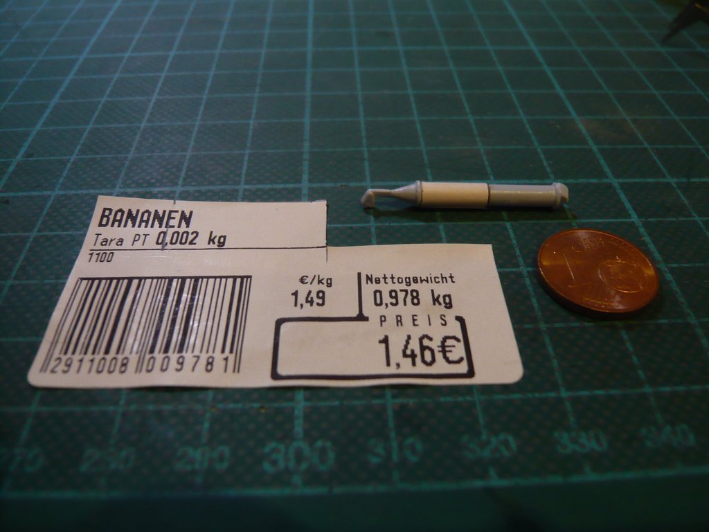
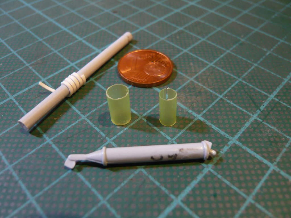
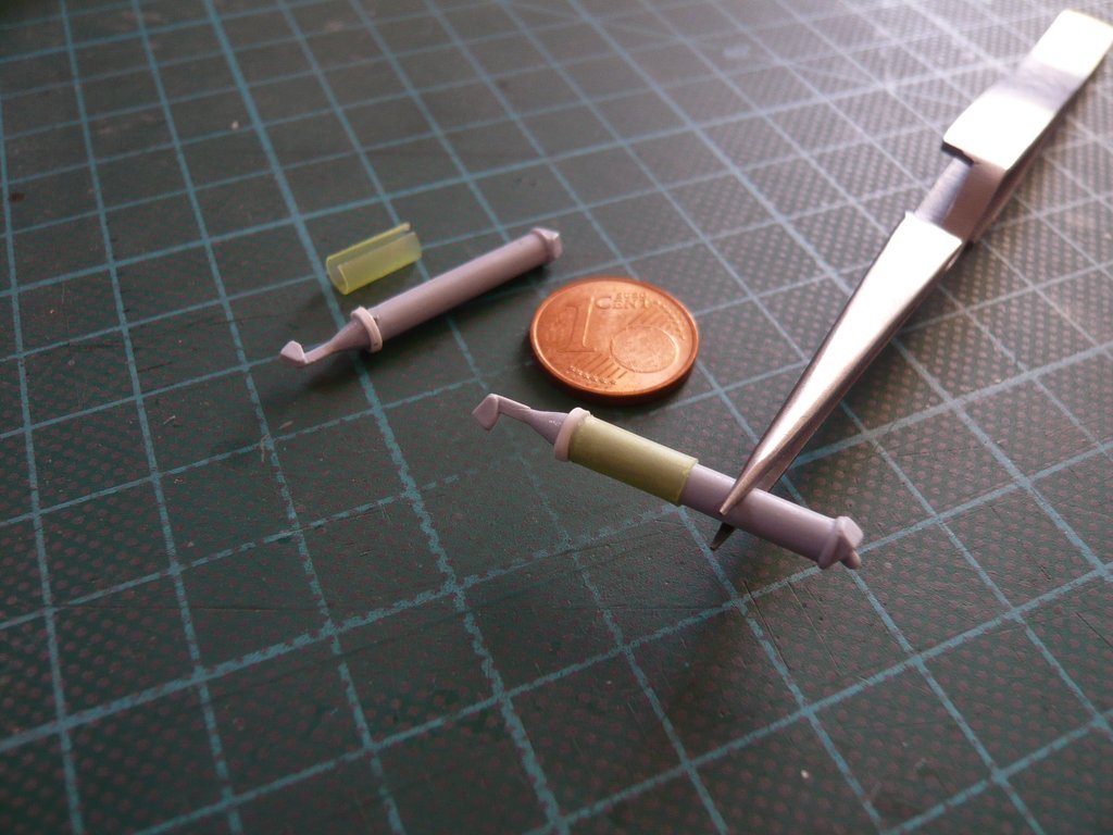
So I had to think about something else and first had thought of adhesive film, as it can often be found in the supermarket as a price label. To do this, I cut a 9 mm wide strip and wrapped it around the strut a few times until it had a diameter of approx. 3,6 mm.

That would also work if necessary, but then one would have to accept the overlap at the end of the winding, which gradually opened again, which I didn’t like.
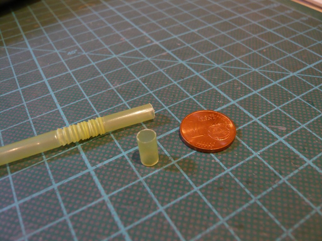
Then I came up with the following idea, and these were the well-known Drinking straws, some of which I had put aside a long time ago. Their diameter is indeed a bit too large at 5 mm, but the wall thickness of approx. 0,2 mm would fit to get the required diameter (Ø 3,6 mm).

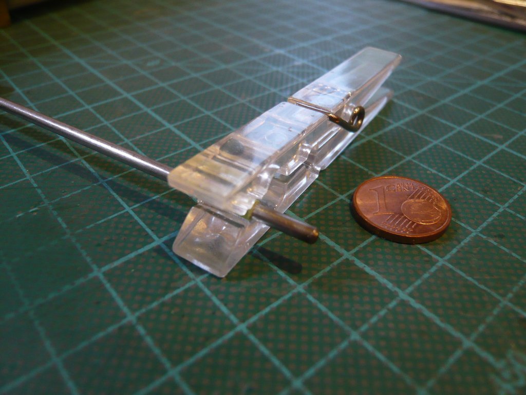
To do this, I’ve slit a 9 mm long sheath lengthways and then wound it as tightly as possible on a steel rod with a smaller diameter (Ø 2,5 mm) and fixed it with a clothespin,

and then placed in a hot water bath for a few minutes for molding.

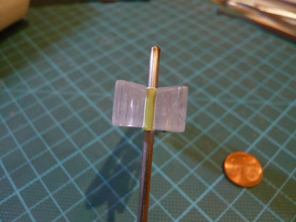
The circumference of the resulting wrapped sheath I’ve then shortened accordingly,

so that there was no overlap on the Airfix strut. BTW, on the left in the image one can already see the prepared spiral for the wider front rings (0,5 mm x 1 mm).

And as the test measurement showed, the required diameter of the sleeve was actually 3,6 mm.

Here one can see a comparison of both variants, whereby I’ve chosen for the lower one.

Before I could glue the sheaths onto the struts, I first had to remove the rings that were too narrow to be able to thread on the wider rings,

that are already glued here.

Then the sheaths could be pushed on and glued.

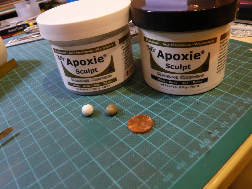
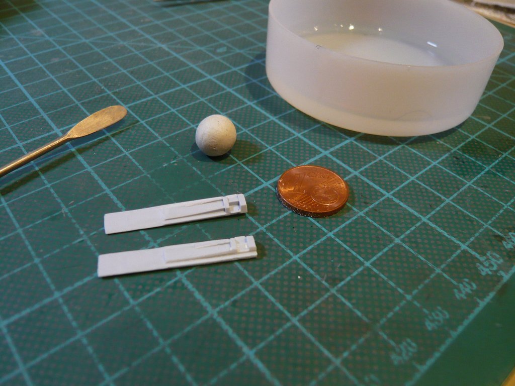
And now still for the modification of the Longerons, for what I’ve used again Apoxie Sculpt, of which both components had to be mixed in a 1:1 ratio by kneading,

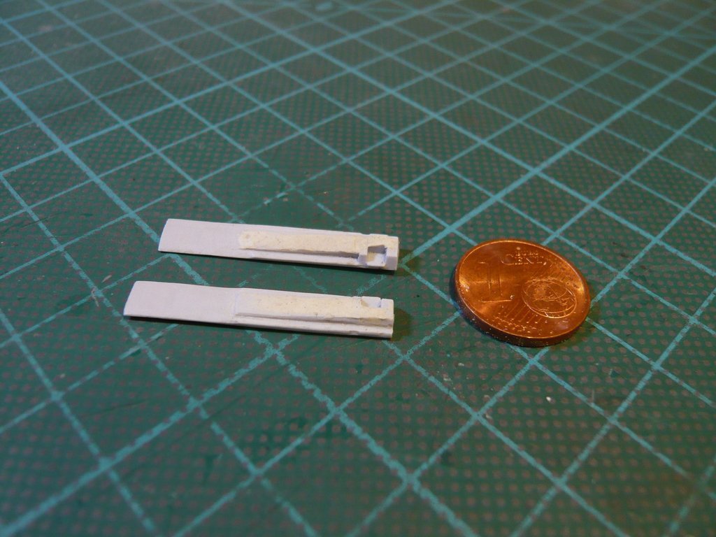
until a bright color appeared. With that it was then possible to fill in and model the middle areas between the slants,

in order to match them to the shape of the real Longerons.

In this condition I’ve let everything dry,

and then carefully sanded from all sides. https://forum.raumfahrer.net/Smileys/yabb/huh.gif

The Thrust Struts are only temporarily layed up and have yet to be glued in. Then the front connecting bolt can also still be scratched.

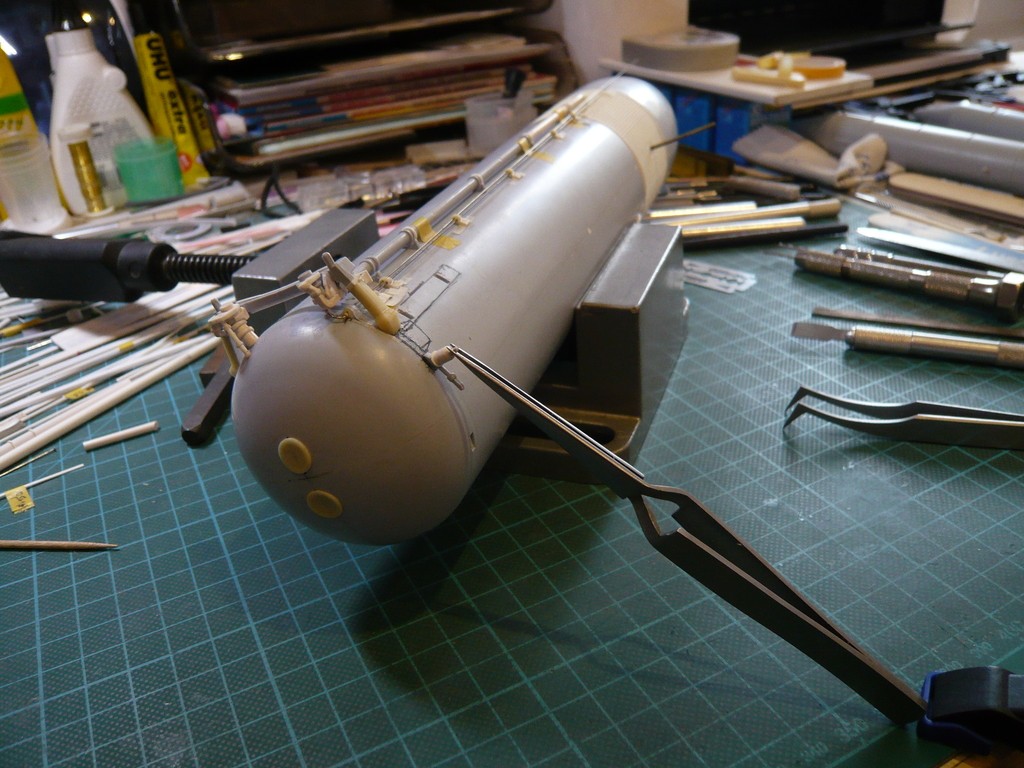
And finally, here is the ET with the temporarily layed up struts & Longerons.

With that it’s enough for today.

7 Likes

Another epic binge catch up. This build never fails in how amazing it is and all the attention to detail. Stunning

Thanks John for your appreciative words. https://www.smiliesuche.de/smileys/lachende/lachende-smilies-0101.gif

Let’s continue step by step.

Hello everybody,

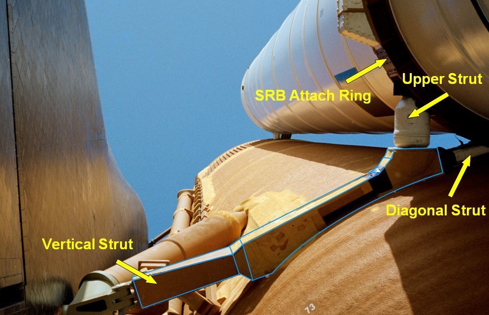
for the masking of the connection areas of the ET Attachments before the Flour process, one interface is still missing, and that is the one between the ET Vertical Struts and the SRB Aft Attach Struts,


Source: forum.nasaspaceflight.com (Jester)

which were unfortunately not taken into account in both the Airfix Kit and the Newware Kit, which results in this gap, which of course should not exist there.

Via the local cable connections running in the Cable tray and through the Upper Strut, u.a. the ignition of the SRB Separation Motors took place, which initiated the separation from the ET after the burnout of the Boosters.

As one can see from the following image, the round cladding of the Upper Strut cannot be overlooked,


Source: forum.nasaspaceflight.com (woods170)

and is not nearly just a puny thing like at the dainty Airfix Strut,

which can also be seen in this photo by Steve Patlan,


Source: live.staticflickr.com (Steve Patlan)

who was close to the action at the time and has great photos in his albums.


Source: live.staticflickr.com (Steve Patlan)

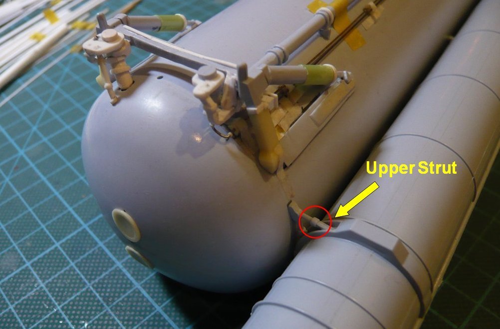
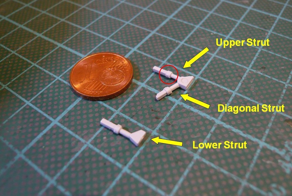
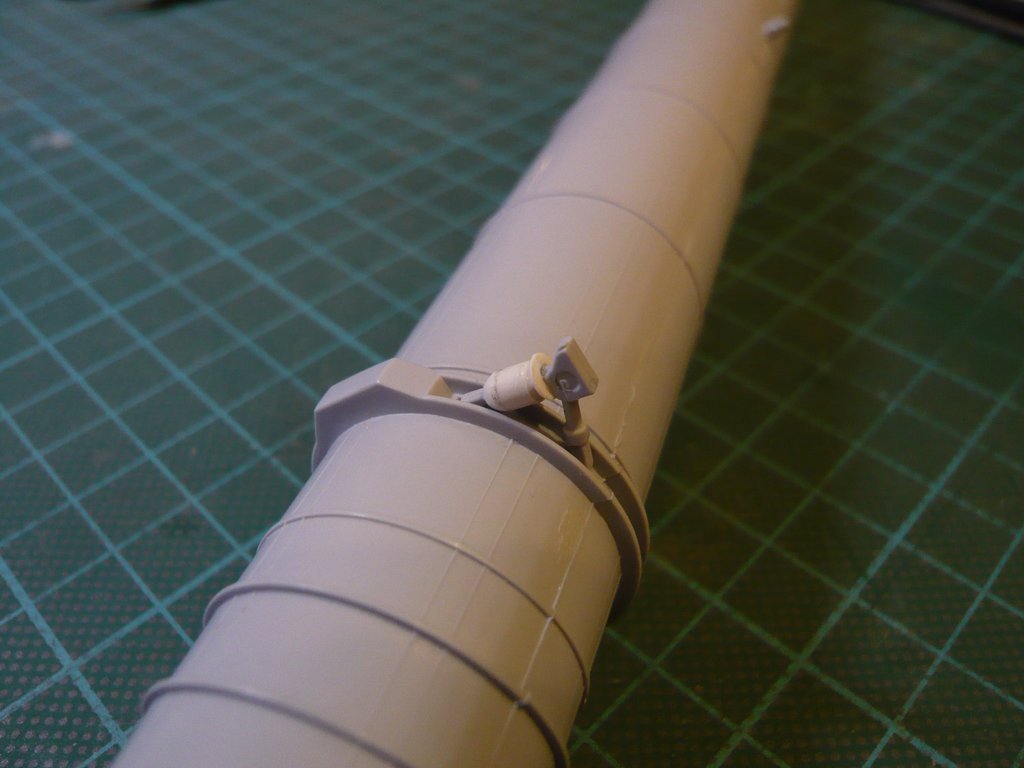
This comparison inspired me to show these details at the interface in a more real way, whereby I was starting with the cladding of the Upper Strut. But since I had already glued the struts at the right SRB, I’ve taken the struts of the left SRB and first removed the annoying bobble.

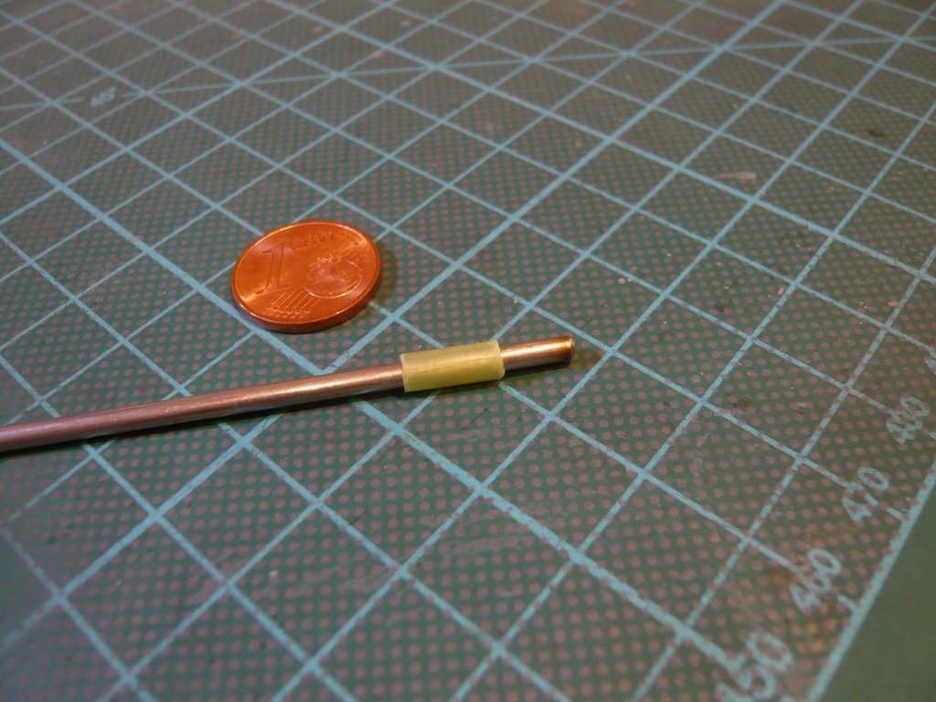
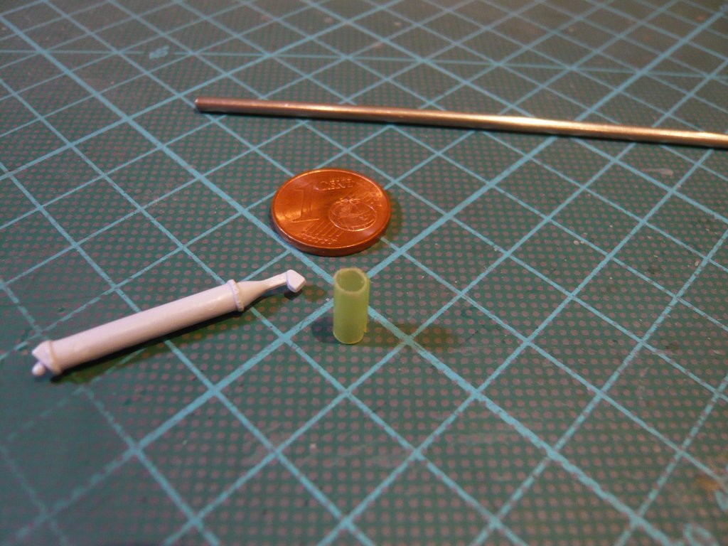
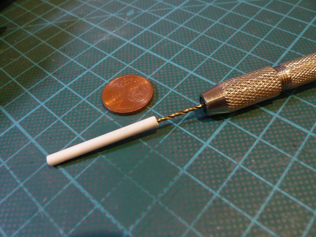
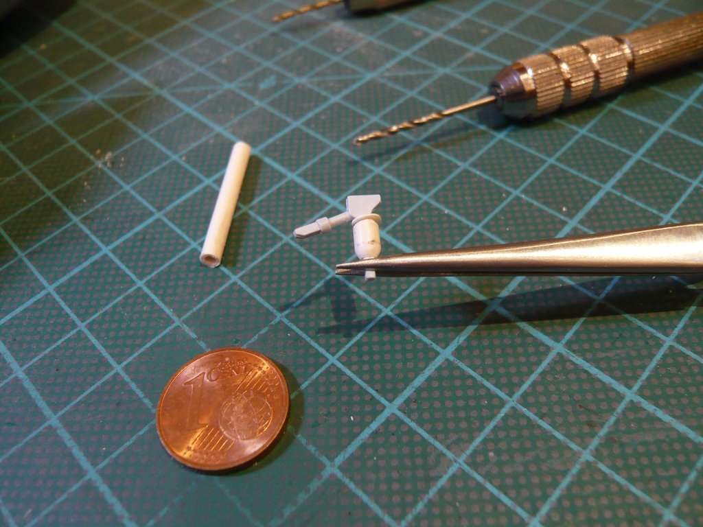
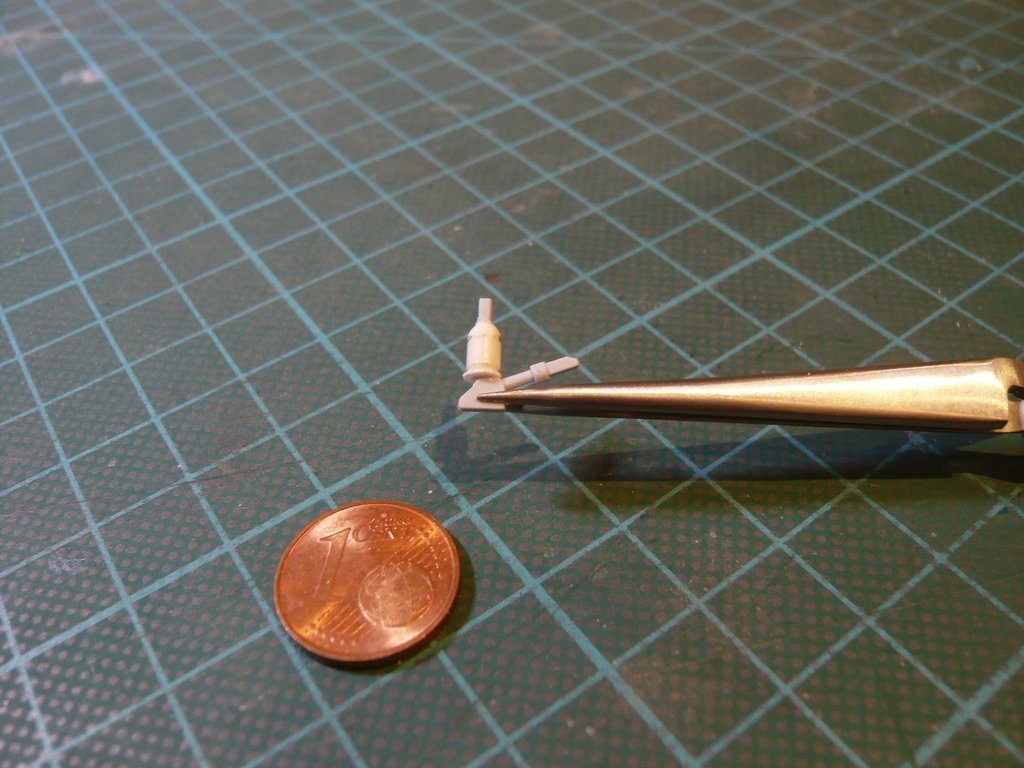
Then I’ve drilled off a Styrene Rod (Ø 3 mm) step by step up to Ø 1,4 mm,

so that a separated sleeve of it could be pushed over the strut. In between there was placed a punched disc (0,25 mm, Ø 3,4 mm),

which then was glued together with the sleeve on the strut, which already looks more similar to the original strut.

The same procedure I will now carry out on the right SRB Strut, for what I will carefully separate it off the booster. https://forum.raumfahrer.net/Smileys/yabb/huh.gif

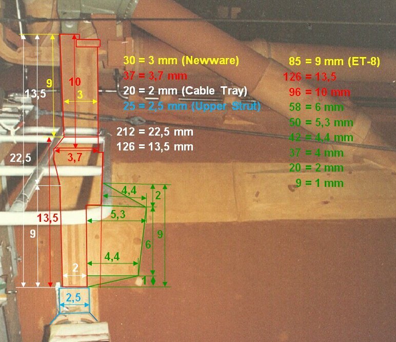
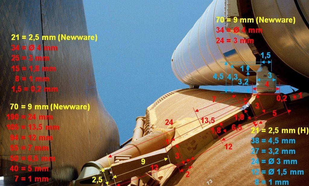
And now once again to the connecting cable tray between ET and SRB Attach Ring, for what I once again did use this overseeable photo of the ET-32 ( STS-32) by George Gassaway, what I’ve turned by 90° for better orientation, from which I’ve also determined the dimensions (in mm) of the individual details.

Therein one can also see well the green drawn TPS Cladding, which lies in front of the Cable Trays like an oblique ramp and should have a similar protective function like those of the elongated LH2/LO2 PAL Ramps in front of the cable trays in the middle and front tank area.


Source: georgesrockets.com (George Gassaway)

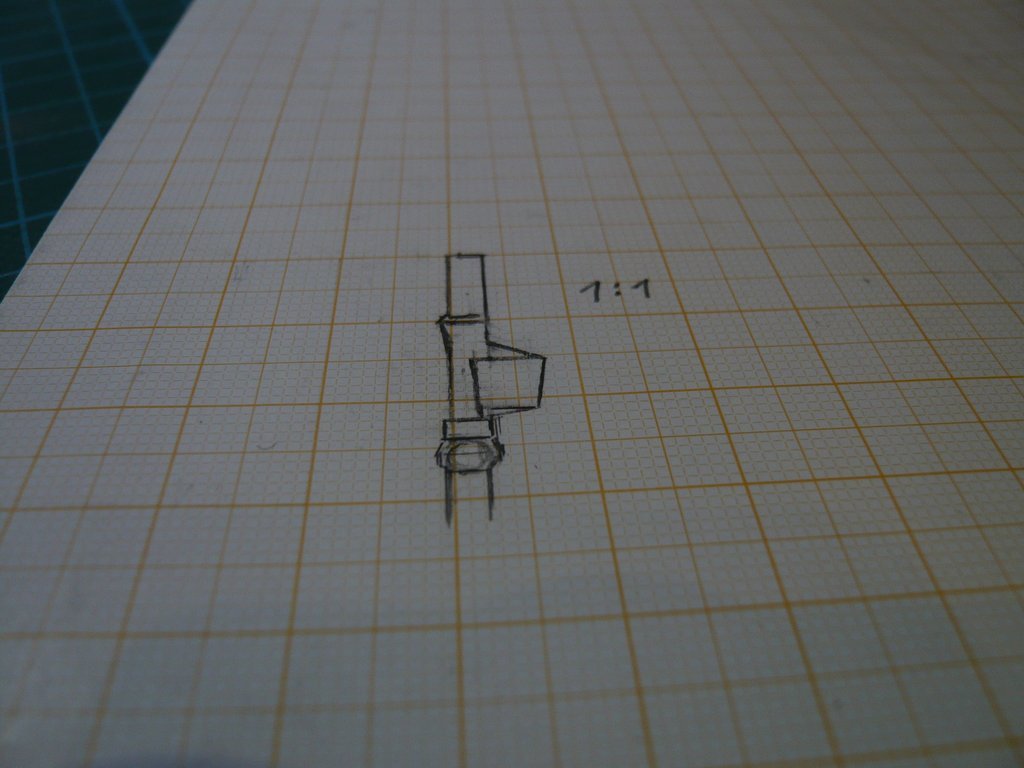
With these dimensions I have drawn this sketch (1:1),

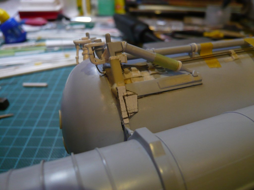
which I then have put onto the interface to try on, with which I can mark the masking areas on the ET.

The remaining dimensions for scratching the parts I’ve determined from this side view,


Source: forum.nasaspaceflight.com (woods170)

wherewith again a further small step was done, which took a lot of time.

6 Likes

Thanks folks for liking, https://www.smiliesuche.de/smileys/lachende/lachende-smilies-0101.gif

I keep clenching my teeth and won’t give up yet …

Therefore stay tuned my friends.

2 Likes

Hello everybody,

don’t panic friends, the show must go on.
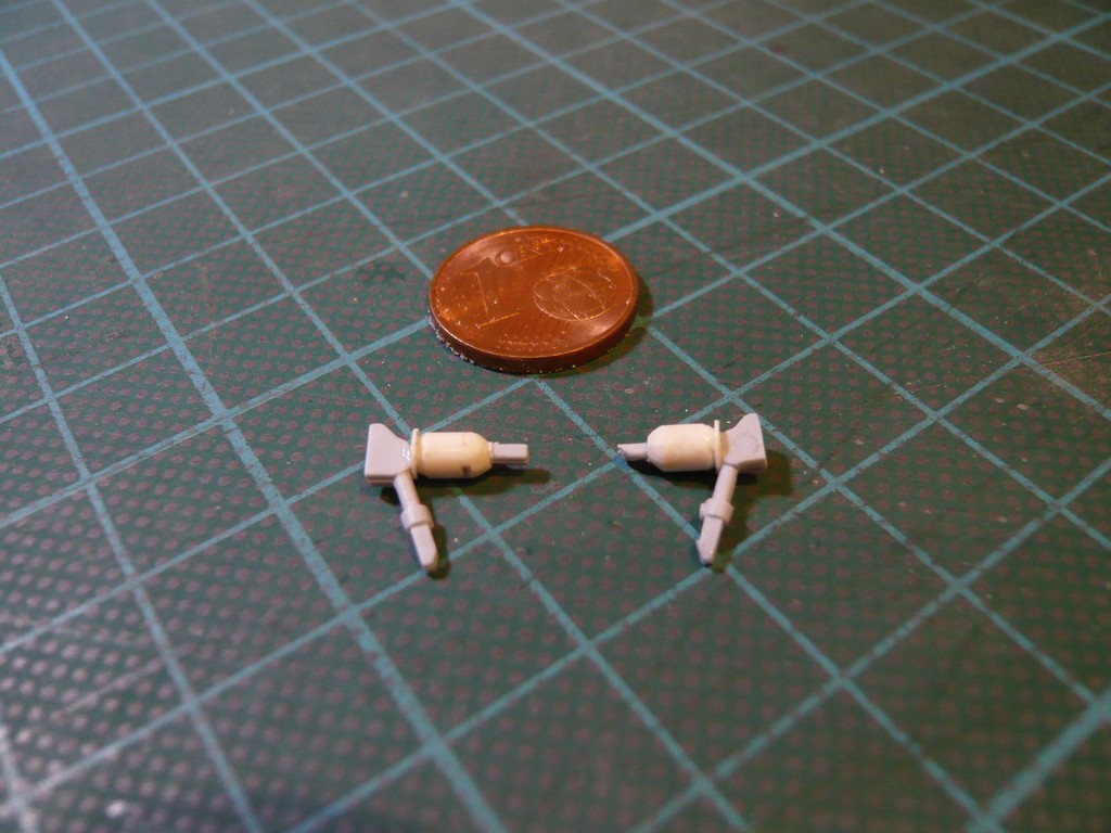
In the meantime, the second SRB Upper Strut (right) has also been modified by the thicker sleeve, but the strut, unfortunately, could not be removed from the bonding without being damaged and therefore has to be lengthened somewhat, so that the distance of the booster from the ET is correct. https://forum.raumfahrer.net/Smileys/yabb/rolleyes.gif
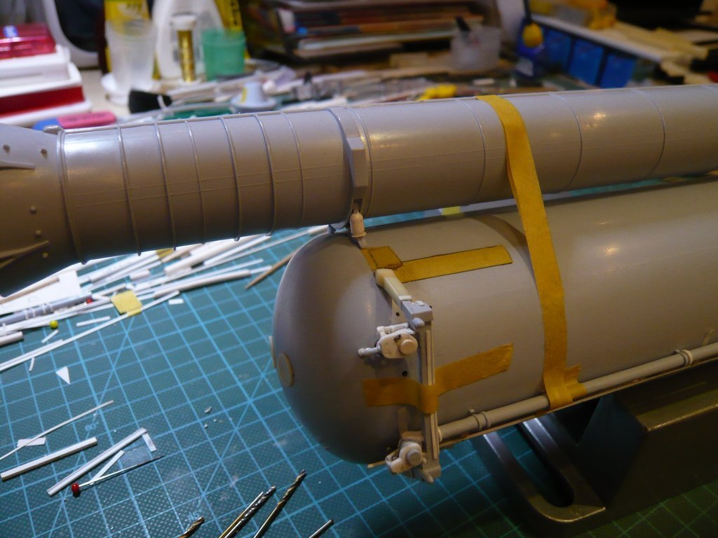
For the test fitting onto the ET, I was able to use it like this for the time being. Then I’ve marked the contours for the Longerons and Cable Trays, incl. TPS cladding,

and then taped them off with tape so that I can expose the adhesive surfaces again after the flouring and priming/painting.

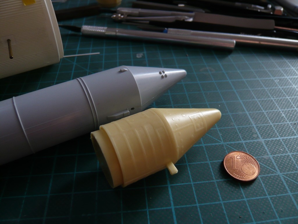
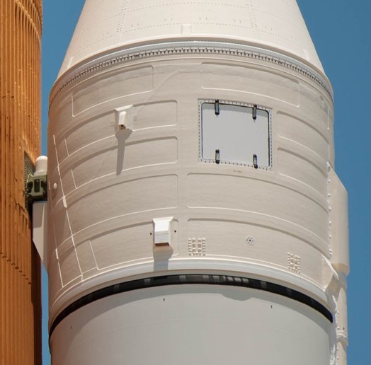
Then I took a closer look at and measured the SRB front parts (SRB Forward Skirts) from the Newware Kit, the surface of which is surprisingly finely structured and therefore looks much more real than that smooth from the Airfix Kit,

whereby they come pretty close to the original.


Source: NASA

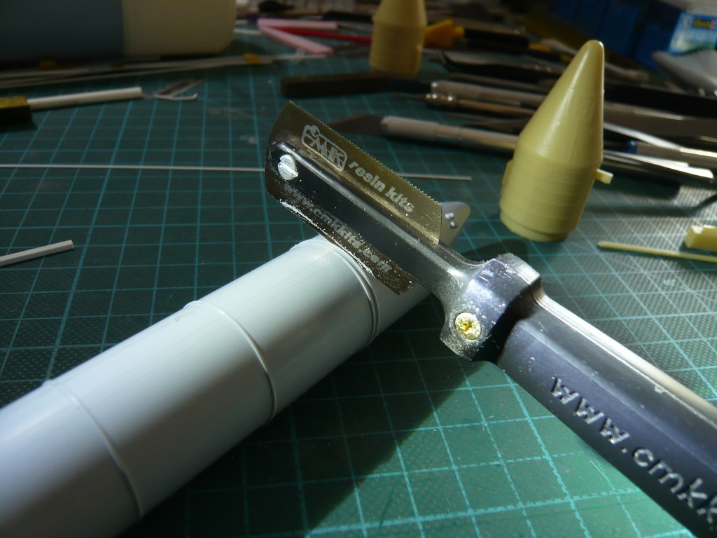
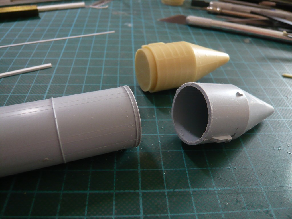
Since the Newware Kit is specially designed for the Revell Shuttle Stack, the question arose whether the SRB Forward Skirts would also match the Airfix-SRBs. https://forum.raumfahrer.net/Smileys/yabb/undecided.gif But since the diameters of the SRBs of both kits are surprisingly the same (Ø 26 mm), I was relieved and have carefully cut off the front part with the fine saw. https://forum.raumfahrer.net/Smileys/yabb/huh.gif

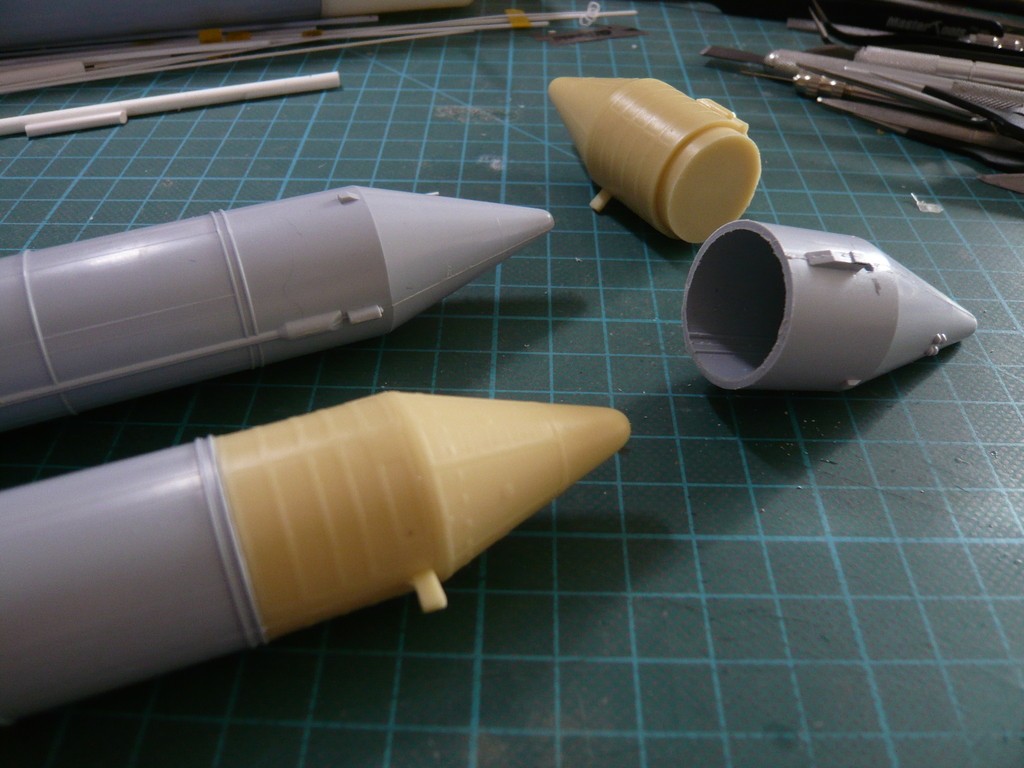
And lo and behold, the Newware Forward Skirt fits like a glove with the Airfix booster.

Now I just have to drill the hole for the brass support rod in the right place and take care that the drill does not run away in the Resin part.

So I’m still trying to figure out how to do it best … maybe there are any thoughts? https://forum.raumfahrer.net/Smileys/yabb/huh.gif

We will see …

5 Likes

Hello everybody,

I actually don’t need to drill 25 mm deep, because 5 - 10 mm should also be enough if I shorten the brass support rod on both sides accordingly. Therewith the boosters’ forward attachment point should be fixed sufficiently and, together with the rear SRB Aft Attach Struts, ensure a stable three-point support of the boosters.

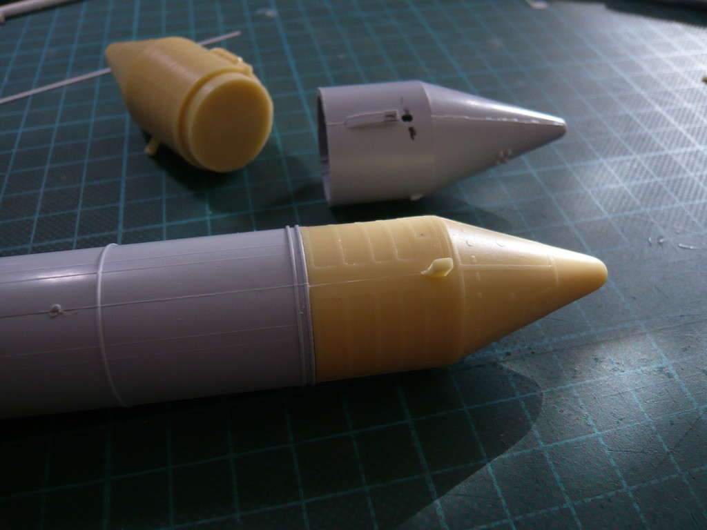
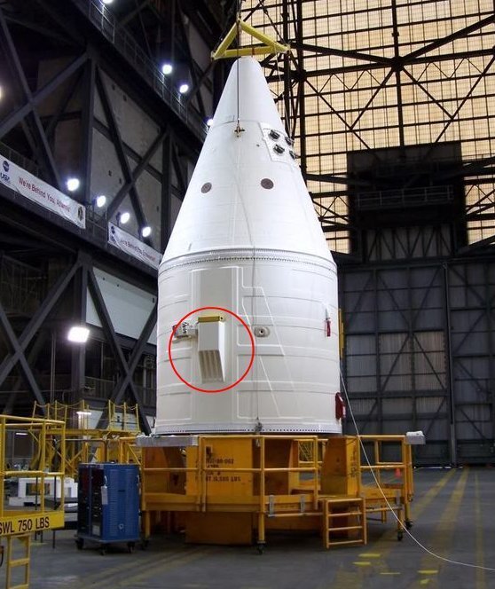
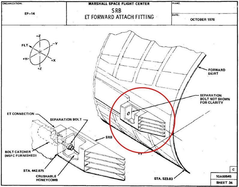
This is this circled wedge-shaped Fastening part (SRB/ET Forward Attach Fitting) between the ET and the SRB, in each of which is a Separation Bolt, which is blown up together with similar bolts in the rear SRB struts when the SRBs are separated from the ET and thus releases the booster.


Source: NASA


Source: Marshall Space Flight Center, Space Transportation System HEAR No. TX-116

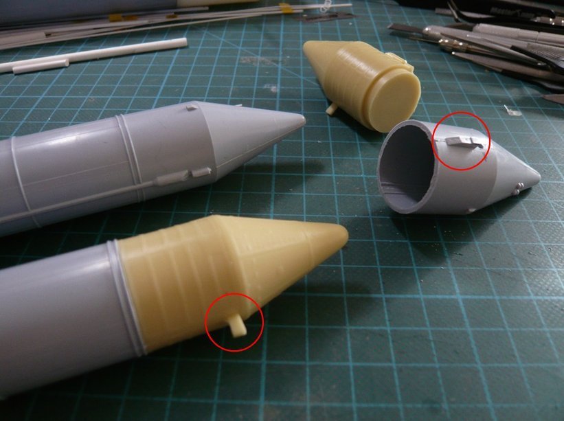
As one can see in this image, this fastening wedge is in place on the Airfix booster, but it is missing on the Newware SRB Forward Skirt, what in turn proves that apparently no kit is perfect. https://forum.raumfahrer.net/Smileys/yabb/rolleyes.gif

Therefore I will scratch this wedge-shaped part and glue it to the attachment point behind the drilled hole for the support rod, with which the attached booster will be glued onto the ET, which should ensure a sufficient hold.

And these 5 - 10 mm deep drilled holes should be carried out by hand with the appropriate caution and care, I hope so.

4 Likes

Hello everybody,

and thus to my test bores in order to test whether the minimum depth of approx. 5 - 10 mm could be achieved by hand with an appropriate caution and care. https://forum.raumfahrer.net/Smileys/yabb/undecided.gif

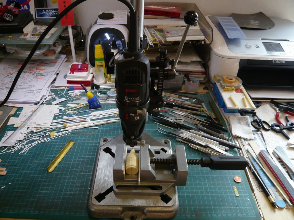
Since my Dremel is already nearly 10 years old, I wanted to test it once again in the associated drill stand, although I had doubts whether the lowest speed of 10.000 rpm already would be overkill and too risky.

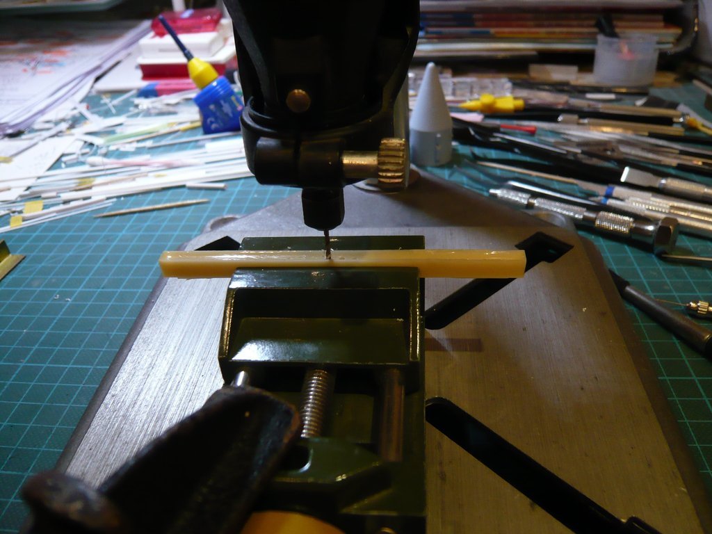
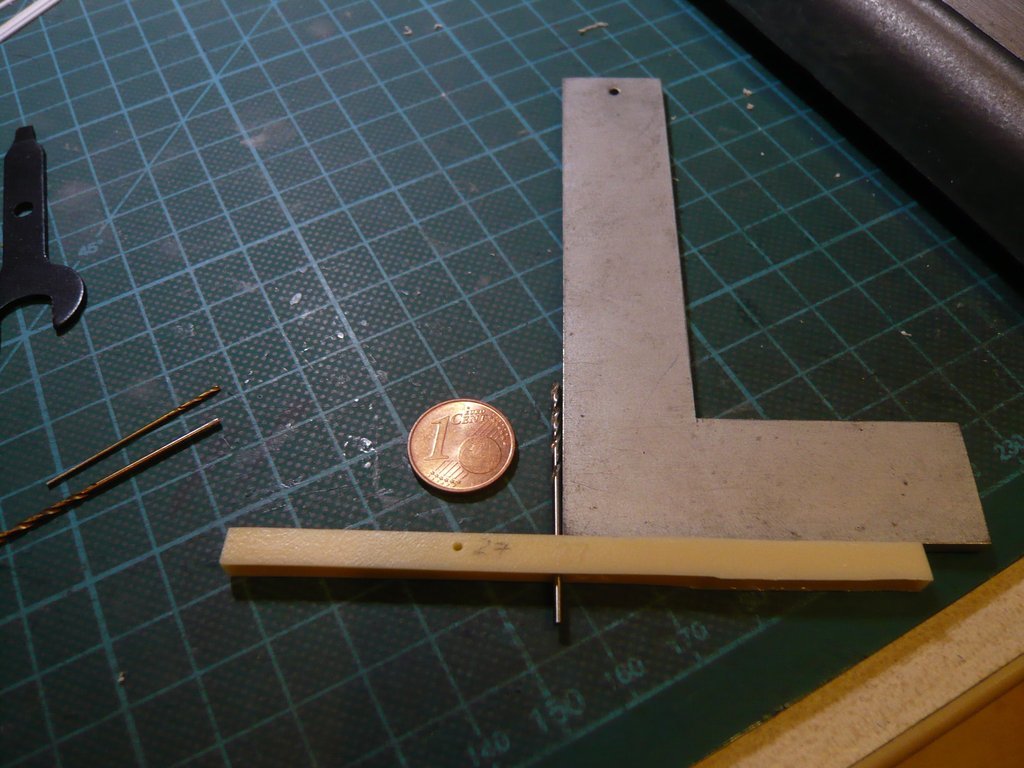
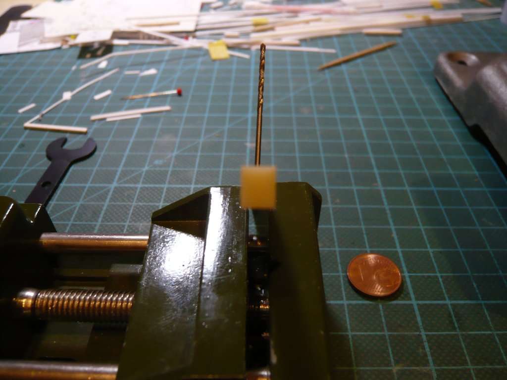
That’s why I started by doing some manual tests true to the motto Better safe than sorry! For this I have clamped a Resin strip in my Mini vice and started turning the Dremel-chuck with a smaller drill (Ø 1,3 mm) in the Dremel-stand with the left hand, while at the same time I’ve soulfully forced down the lifting rod with my right hand, what was not so easy.

While the orthogonality of the bore in longitudinal direction was acceptable, https://forum.raumfahrer.net/Smileys/yabb/huh.gif

it left something to be desired in the transverse direction, https://forum.raumfahrer.net/Smileys/yabb/rolleyes.gif

which is why I was not completely convinced of this hand-drilling variant.

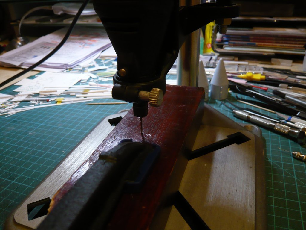
Therefore, in a second series of tests with the Dremel in the drill stand I have drilled at the lowest speed (10.000 rpm) in a Chipboard with Ø 1,3 mm,

what went smoothly.

Then I’ve drilled with Ø 1,4 mm and then took a look at the orthogonality of the bore in the longitudinal and transverse directions, which looked surprisingly good at least over the minimum length.

Then I’ve drilled with the diameter of the SRB support rod (Ø 1,5 mm) and tested again in both directions, whereby the orthogonality was still unchanged good.

And the support rod also fit well into the bore, which was about 15 mm deep, which should be sufficient for the stable fixation of the boosters in my opinion, whereby I still could then drill a bit deeper with a Mini hand drill.

So I could now venture on the bore of the two SRB Forward Skirts from the Newware Kit, whereby in addition to a stable support in a corresponding holder, especially the skirts have to be precisely aligned so that their bores are in line with the support rod.

4 Likes

Hello everybody,

so far so good.

Next, I’ve determined the position of the base point for the bore of the Support rod, which was not so easy, because it could not be marked in the narrow space, which is why I had to improvise a little bit with masking tapes. https://forum.raumfahrer.net/Smileys/yabb/huh.gif

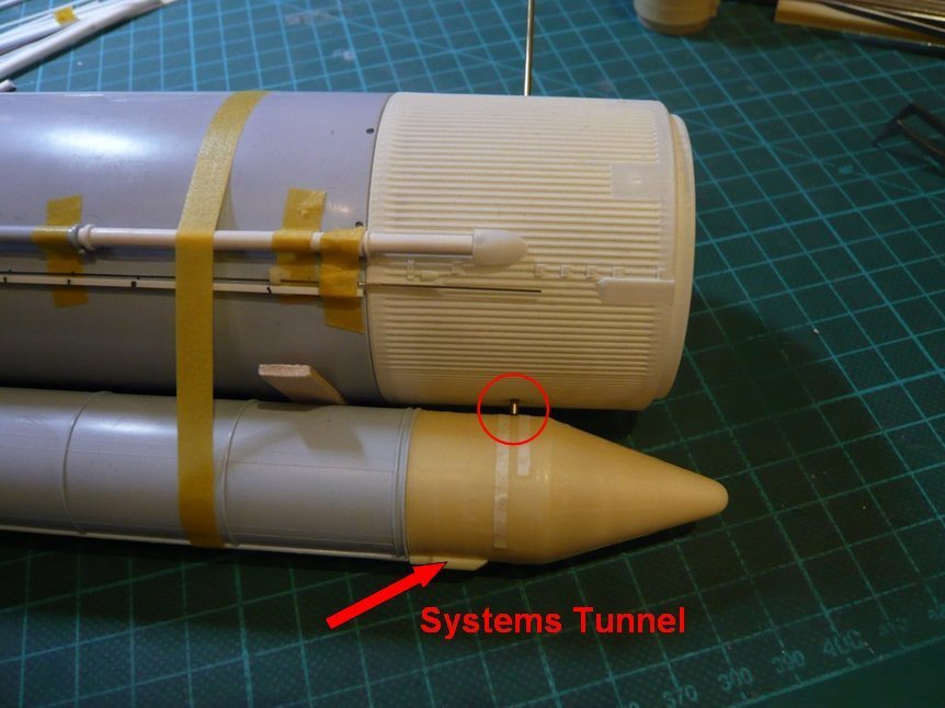
The next problem was the necessary level support of the part as a prerequisite for an exact drilling, which was also not easy due to the disruptive Systems Tunnel at the bottom, which is why an exact clamping in the vice was rather difficult.

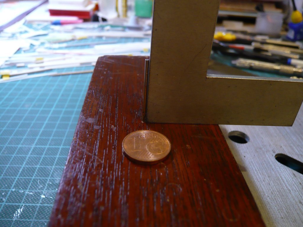
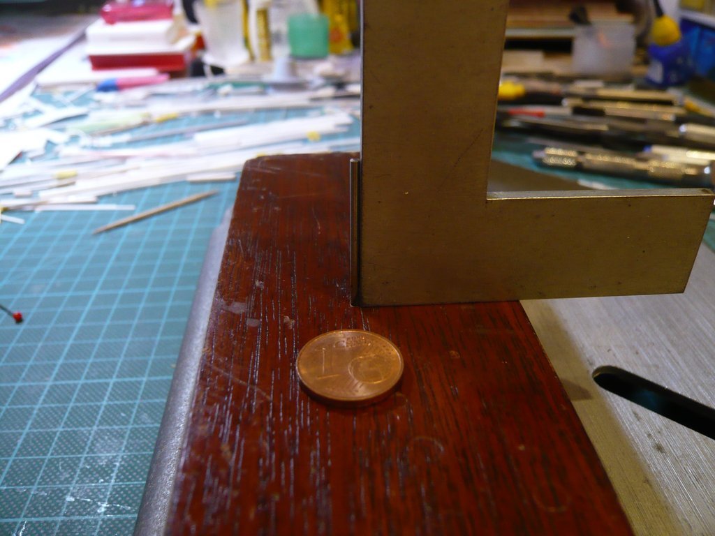
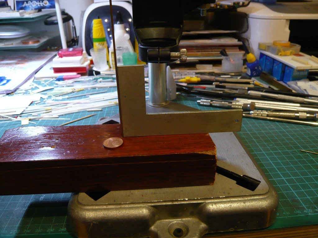
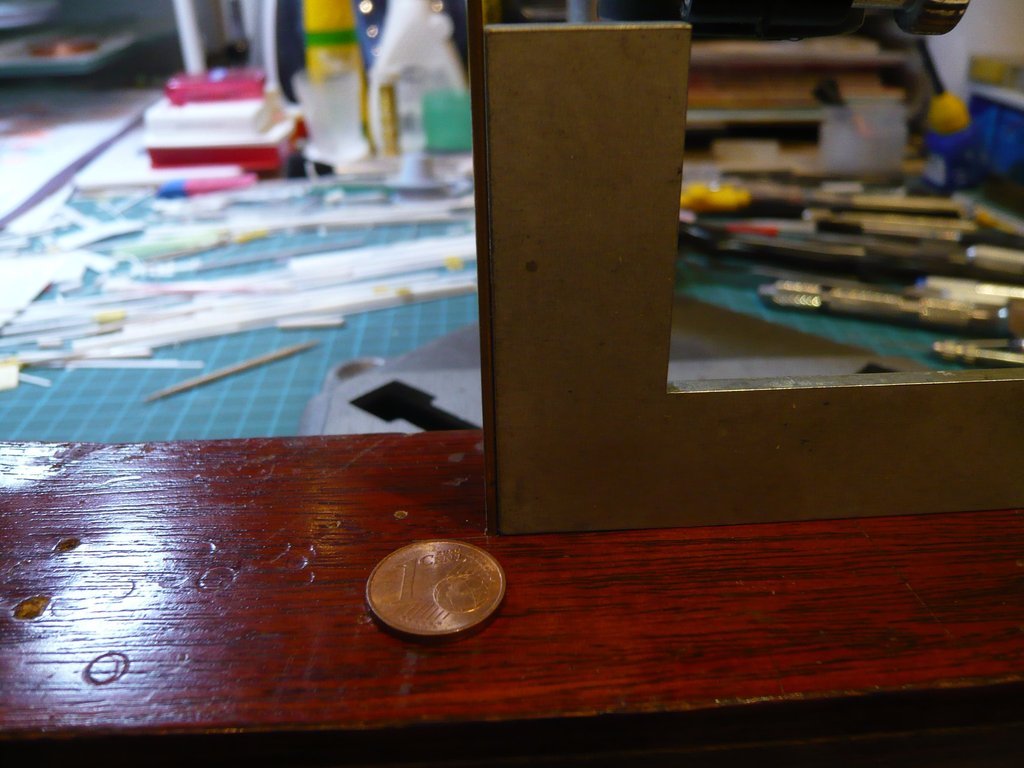
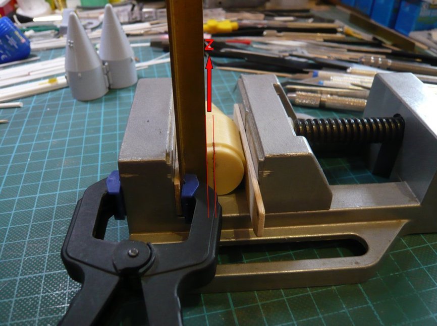
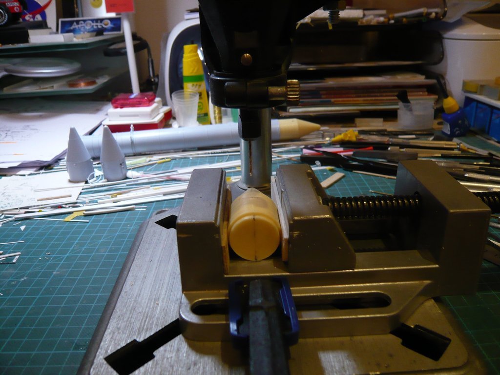
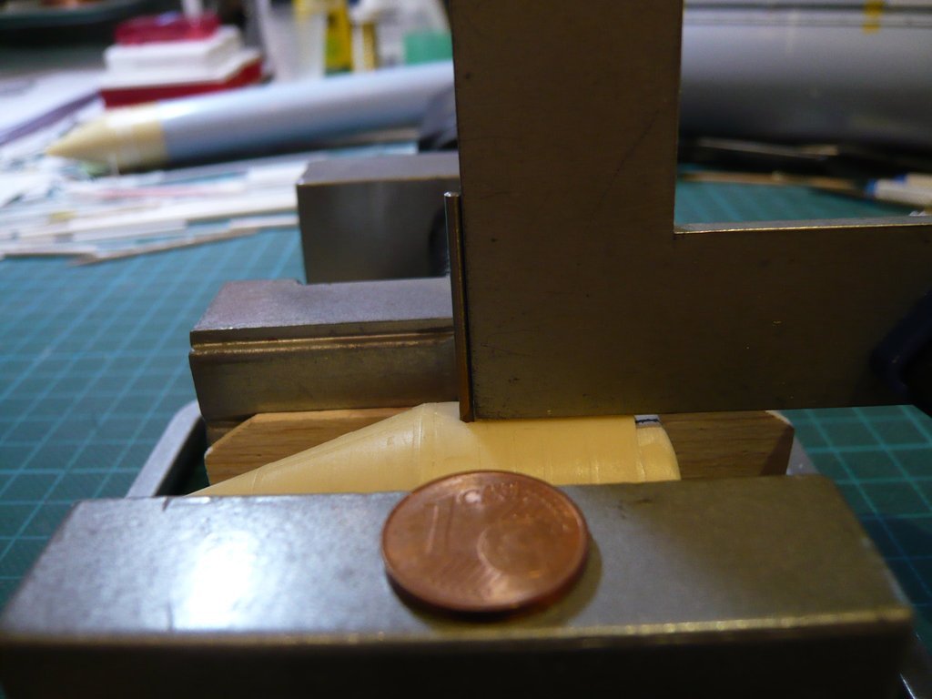
That’s why I clamped a brass angle for orientation in the Z-direction,

and aligned the center line on the back of the part as good as possible parallelly.

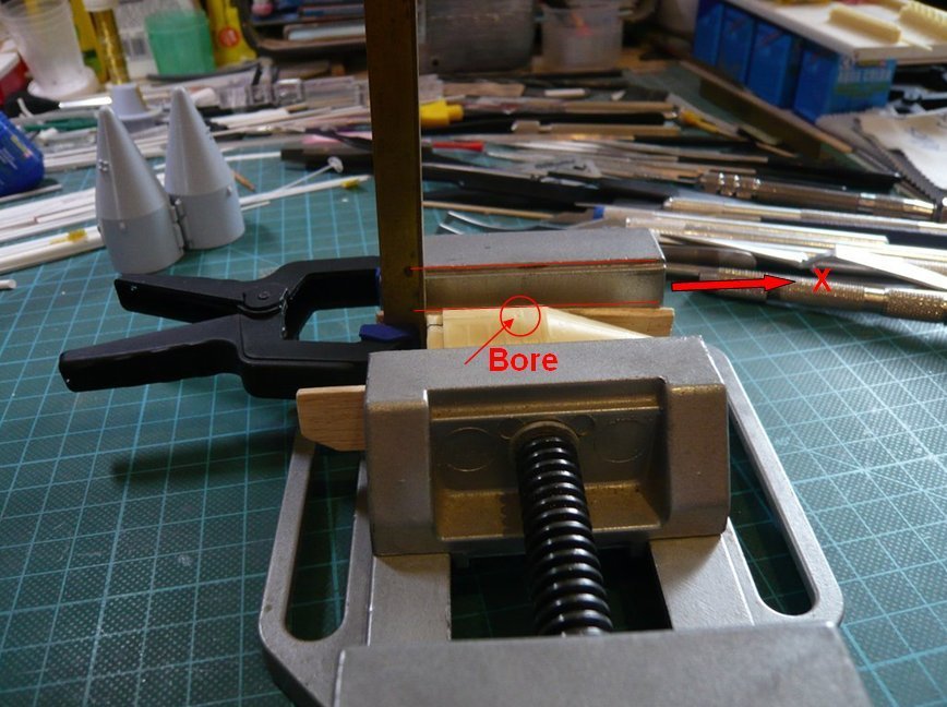
For the alignment in the X-direction I oriented myself on the upper edge of the vice. https://forum.raumfahrer.net/Smileys/yabb/huh.gif

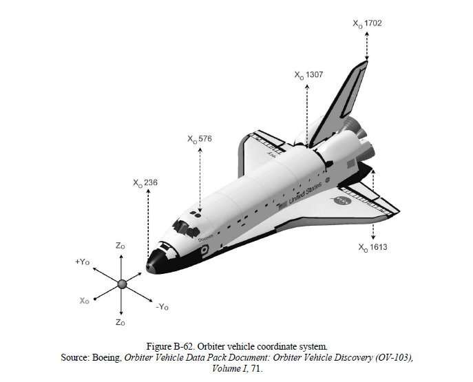
For better orientation here one can see the Orbiter vehicle coordinate system.


Source: Marshall Space Flight Center, Space Transportation System HEAR No. TX-116

And in this position I will try now drilling the hole, again step by step, carefully pre-drilling with Ø 1,3 mm, and then drilling out with Ø 1,4 mm and Ø 1,5 mm.

Hopefully I can do this successfully, so please keep your fingers crossed! https://images.raumfahrer.net/up050224.gif

3 Likes

Hello everybody,

and therefore: Nothing ventured, nothing gained! - Let’s get on with it!

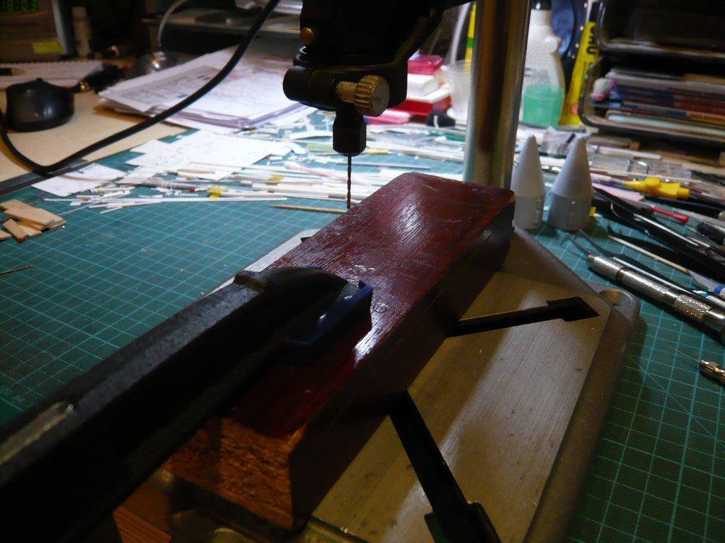
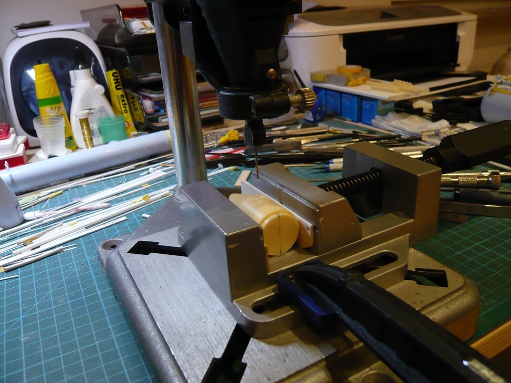
Before with drilling it could really come down to business, the vice onto the drill stand was carefully aligned so that the drill came to stand directly over the pre-drilled hole, whereupon this arrangement was then firmly fixed to the table top with a screw clamp.

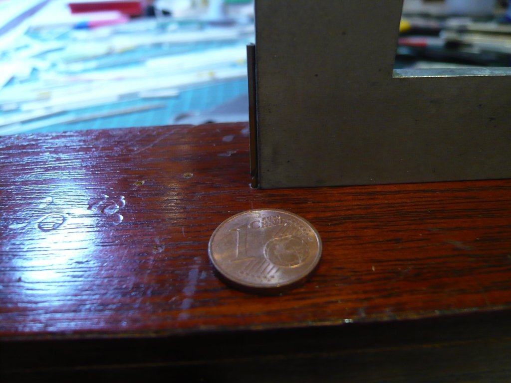
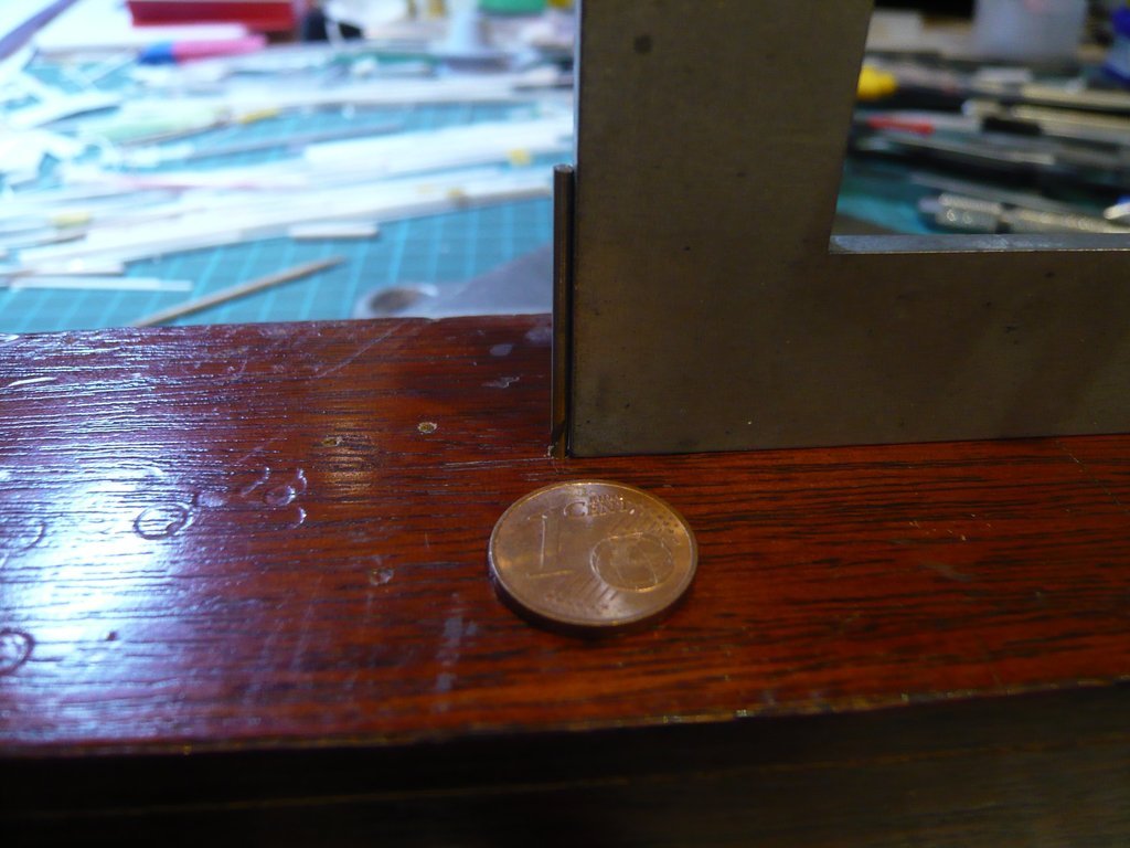
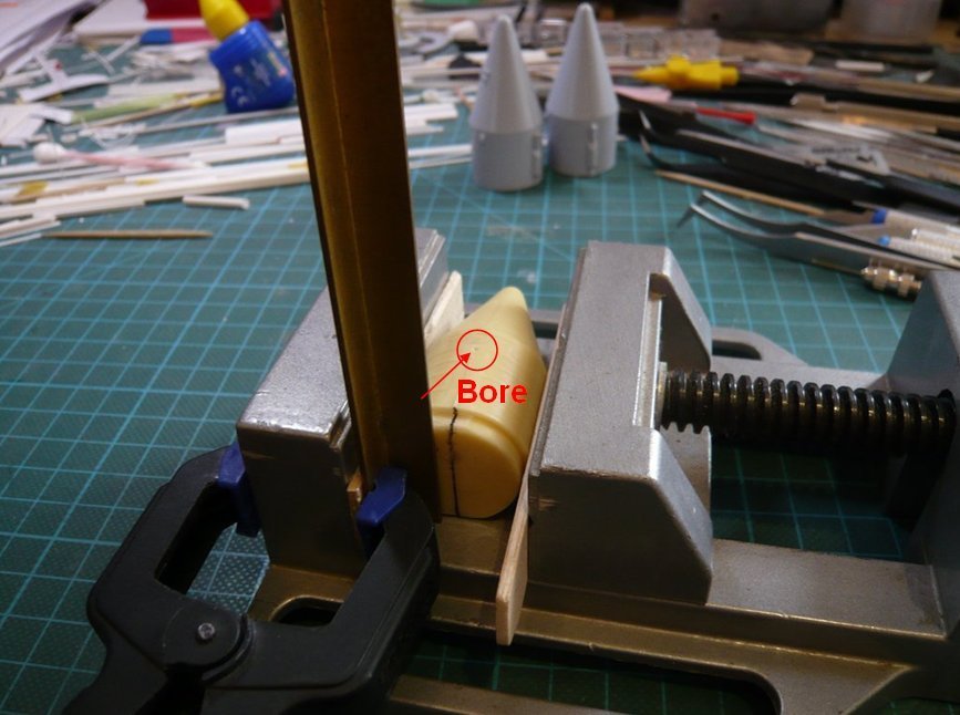
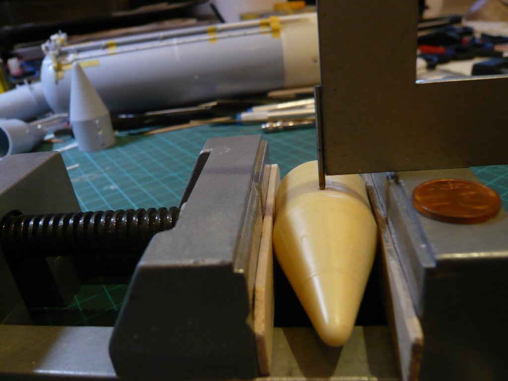
Then, as with the test bores, the holes were drilled step by step, first carefully pre-drilled with Ø 1,3 mm, after which this bore was then drilled out with Ø 1,4 mm and Ø 1,5 mm to a depth of approx. 20 mm.

And as the following two images show, the orthogonality was surprisingly good in both directions.

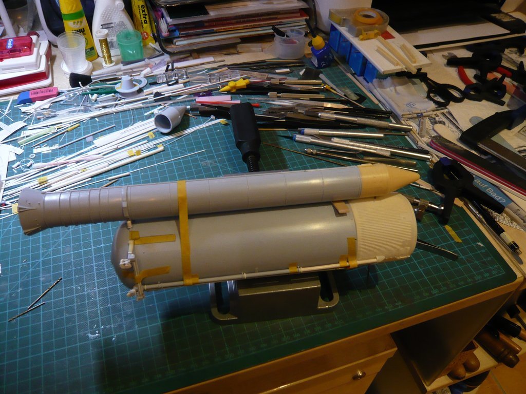
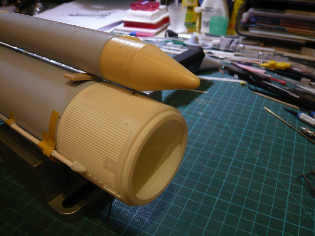
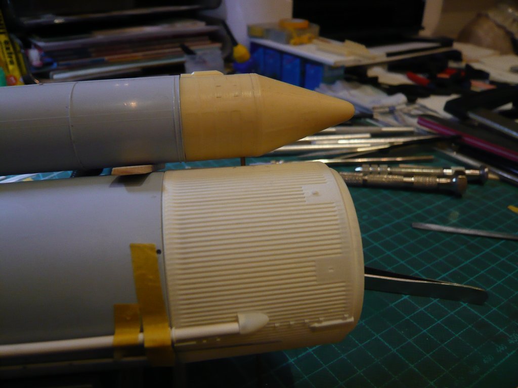
Then the front part was inserted into the booster and with the bore put onto the Support rod in the Intertank, as well as put down with the two rear struts above the openings at the ET’s rear,

whose feet had to slightly ground until they fit in the openings.

At the front end a Balsa board (2 mm) was inserted as a spacer,

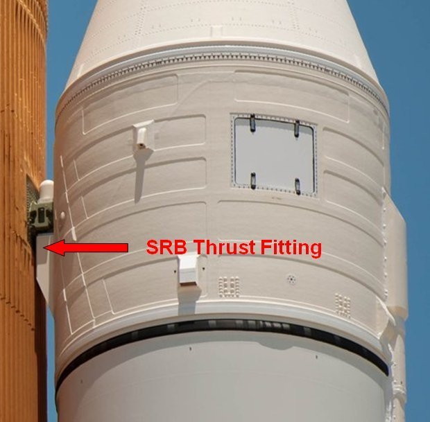
since the already mentioned SRB Thrust Fitting has to be glued directly behind the support bar, which is unfortunately missing at the Newware front parts, https://forum.raumfahrer.net/Smileys/yabb/rolleyes.gif


Source: NASA

which is why I have to scratch this part.

3 Likes

Doing nice as usual. However, l just realized I missed the news of New Wear PE and resin set for the 1/144 booster kit. I have their set for the 1/144 Space Shuttle and few others but did not know about their items to detail up this kit. I’ll have to check it out as it’s nice looking set according to what you have shared.

1 Like

Hello Mike,

not New Wear, but the Space Shuttle/Booster Enhancement Kit Newware131 (1/144) is really a great Kit.

1 Like