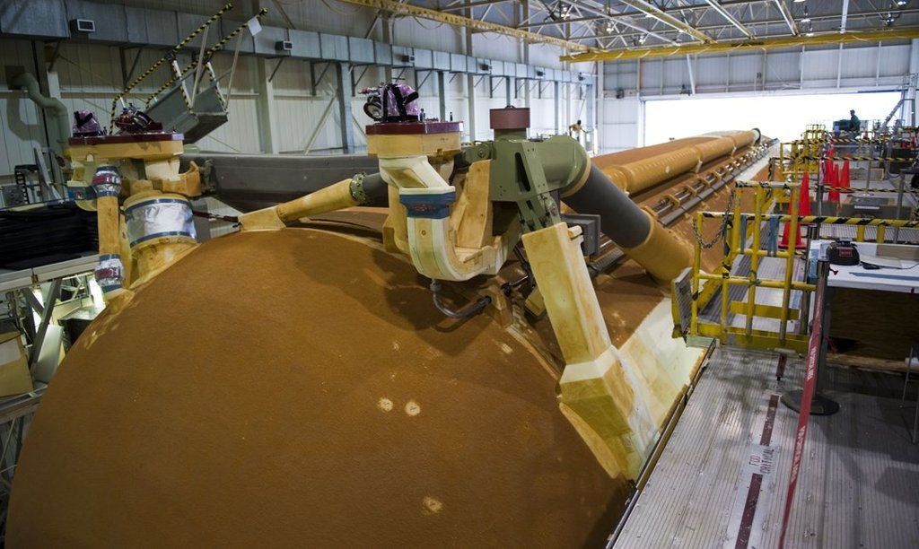
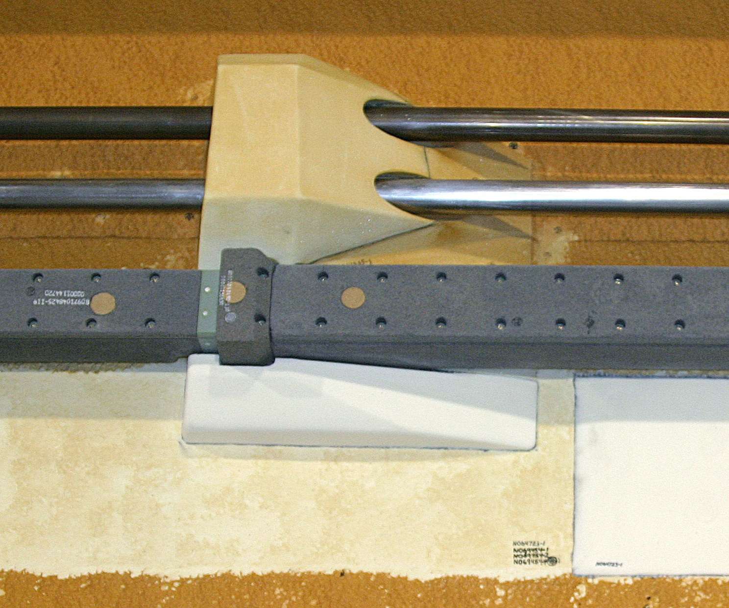
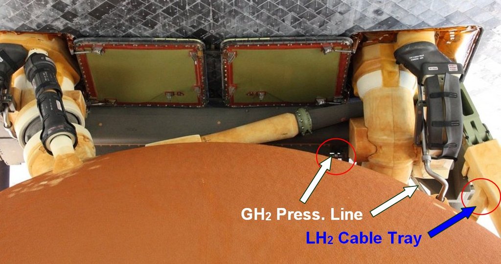
OMG, I think I need to stop posting. 

OMG, I think I need to stop posting.
Hello everybody, but take care of your eyes. 
Then let’s continue with the adjustment of Part 2, for which here beside the Crossbeam (Ball Interface Fitting) the announced narrow recess was cut out with this Mini saw blade. 

And as one can see, it’s only a small cut, but leads to a clear improvement! 

Speaking of Original arrangement, I’m not sure anymore when I take a closer look at my black and white reference photo of the tank ET-8,  which as is well known was to be the firstly flown Lightweight Tank (LWT), that was used since STS-6. Only at STS-7 was used a Standard Weight Tank (SWT) once again, for whatever reason.

Unfortunately, the resolution of the photo is not exhilarating even in the zoom, and the area of interest to me is in the dark and is unfortunately also obscured by the Vertical Strut. 
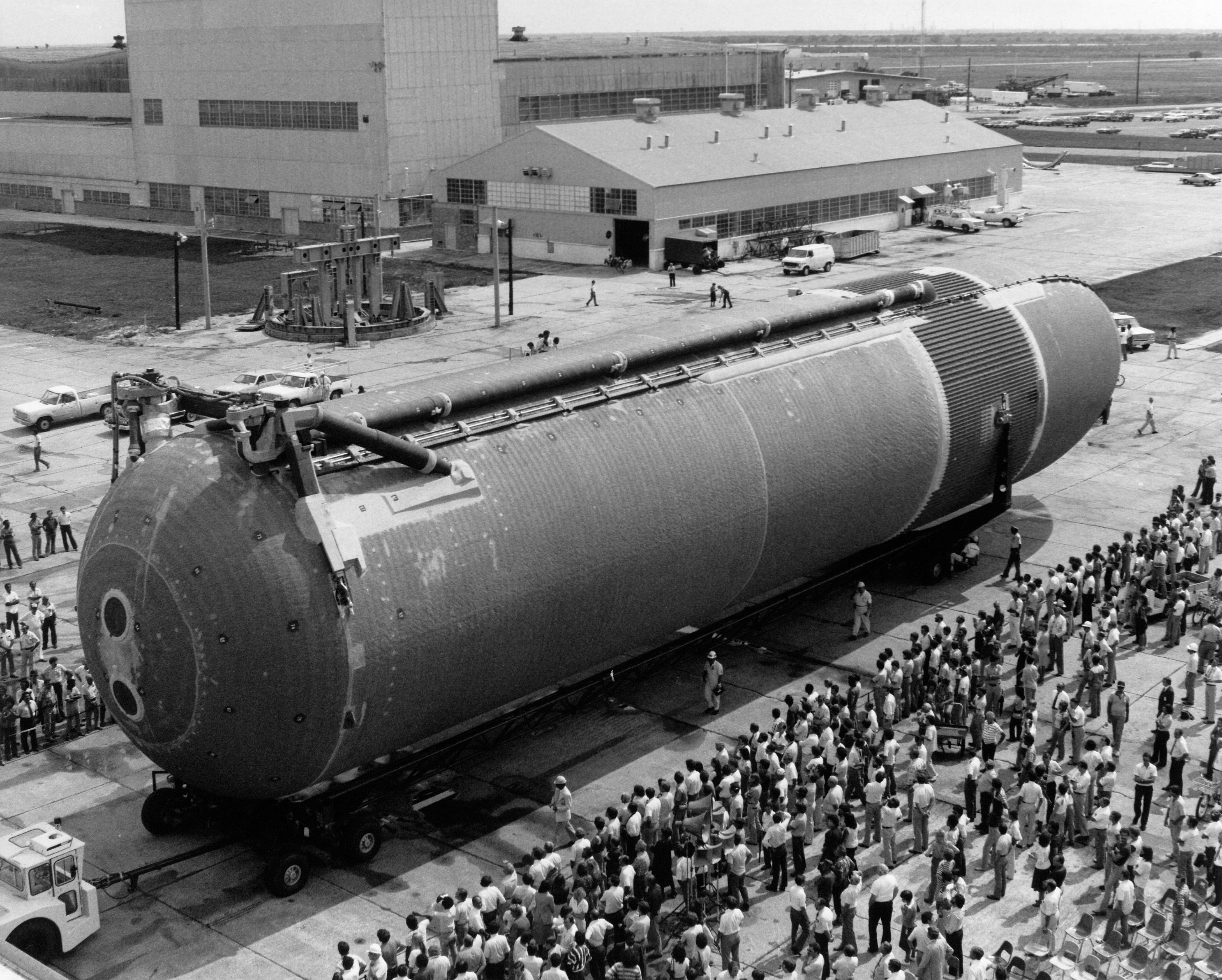
Source: forum.nasaspaceflight.com (Jester)
But if you bend your eyes and look more closely, one recognizes, I believe, that especially the obliquely upwards running part of the Cable tray behind the support (Part 2) seems to be much narrower than on the previously considered images, which however, from later missions, where starting from STS-91 the Super Lightweight Tank (SLWT) was used, which had been modified again. 

To the following photo I will still inquire DaveS, from which mission it originates. 

Source: forum.nasaspaceflight.com (DaveS)
And this photo shows the ET-122 at the last mission of the Endeavor (STS-134).
Let’s see if I can get some more information from DaveS, because sometimes he still has cool photos in his hindquarters, which have already solved some riddles. 
Hello everybody,
and DaveS’ answer was not long in coming.  He can not remember the mission from which his great photo came from, but as far as he knows, the Cable trays did not change during the Shuttle program and remained same from ET-1 (STS-1) to ET-138 (STS-135), which I did not want to believe at first.
Because similar to here on the ET-8-Photo,

Source: forum.nasaspaceflight.com (Jester)
also on this photo of ET-129 (STS-126) at first glance the obliquely rising CT part (red arrow) in front of the middle strut seems to be lower than the horizontal part (yellow arrow) behind the strut. 
And also on this great photo of DaveS it looks similar at first. This photo gives the widest possible insight to below the Crossbeam, where one can see the further course of the cable tray very well. 

Source: forum.nasaspaceflight.com (DaveS)
And so my previous perception is obviously an optical illusion, as I have now recognized in the zoom, if one waits until the zoom bar disappears at the bottom of the screen.

In it one can see a dark area in the lower part of the oblique rise, which I have not recognized so far. This is evidently a dark taped area similar to that at the top of the CT bow below the plate (Part 4). 
It becomes even clearer if one goes to 100% zoom in full-screen mode. 

And if one takes a closer look at this image of the ET-129, one can see the same dark lower part in the zoom.
Therefore I suppose that also the Cable Tray on the ET-8 looked exactly the same, only that one could not see the area even in the zoom, especially because it did lay completely in the dark too.

This confirms the statement of DaveS, that the Cable Trays did not change during the Shuttle Program, wherewith I now finally can go over to scratching the Part 3.
In doing so, I will essentially focus on the following known images.

All I have still to do is think about how to proceed in the most appropriate way.
In any case, I will scratch the bow and the slant as separate parts and then connect. Since the bow with 1,5 mm x 6 mm x 4 mm is relatively small, the question arises, whether I am file out the whole part, or just the actual bow (Part 3.1), and then glue on the two tiny Parts 3.2/3.3?
How do you think about it?
I would suggest the slightly easier path – file it. If that doesn’t look satisfactory you could presumably continue filing until flat and then add the two pieces.
Thanks Tim for your thoughts. 
Hello friends,
because the bow incl. the TPS Cladding on the LO2 Side compared to the one on the LH2 Side is nearly “huge”, as can be seen here at the ET-118 (STS-115),

it would be an unnecessary and vain effort trying to file out the whole part, as for the LH2 Umbilical. 

So I’m going to bend an Evergreen profile (1 mm x 1,5 mm) again using my proven Balsa-aided Bending Technique under hot air around a Balsa stencil.
For this I first printed this drawing as a template on a scale of 1:144 in order to search for a corresponding Balsa stencil for the bow,

Source: System Definition Handbook SLWT, Vol. II (Lockheed Martin)
and have actually found one in my Balsa collection. One only has to keep in mind that the Cable tray in the drawing has no TPS cladding  and is therefore a bit thinner than in reality.

And then it went to the Balsa-bending table, on which the rectangular profile was clamped in a known manner between two small Balsa boards.

Thereafter, the Hot air gun was started and the rod bent under the stream of hot air around the template, fixed immediately and once more blown on hot again.

After the bow could cool off for a while and this shape was “frozen”, I removed the small board and could convince me of the success of the bend. 

And so I could go on,

and have immediately marked the Length (6 mm) and the Height (4 mm) of the bow.

Now I still have to determine the end point of the part in front of the Crossbeam. Then I also know how long the Part 3.4 may be and can then scratchen this. 
Anyway, I’m very satisfied so far and I hope it stays that way.
Thanks my friends for liking.
Hello everybody,
next, I’ve cut off the two tiny Closeouts from an Evergreen strip (0,25 mm x 1,5 mm), as well as sanded a bit,
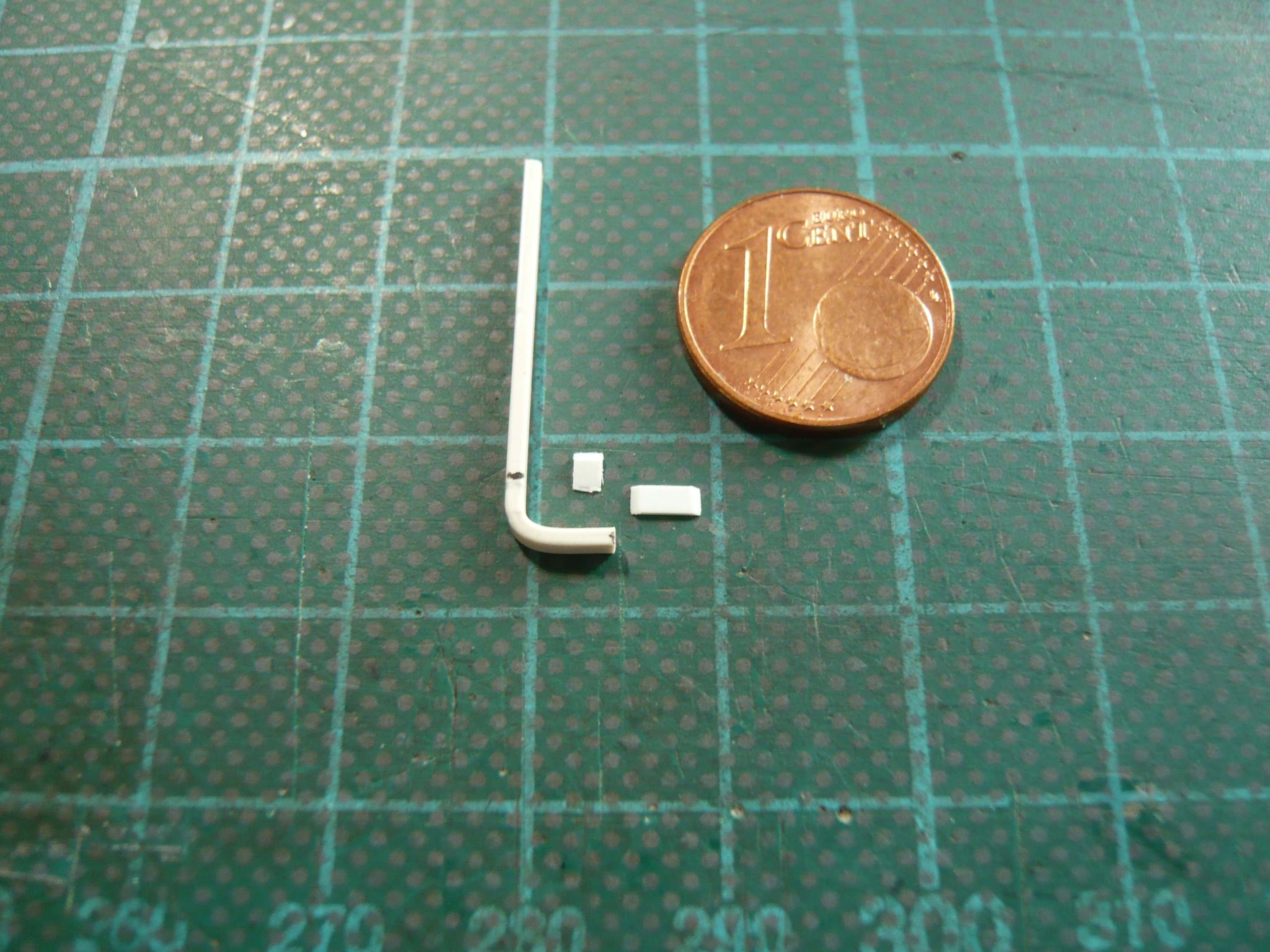
and glued them on the bow (Part 3.1).
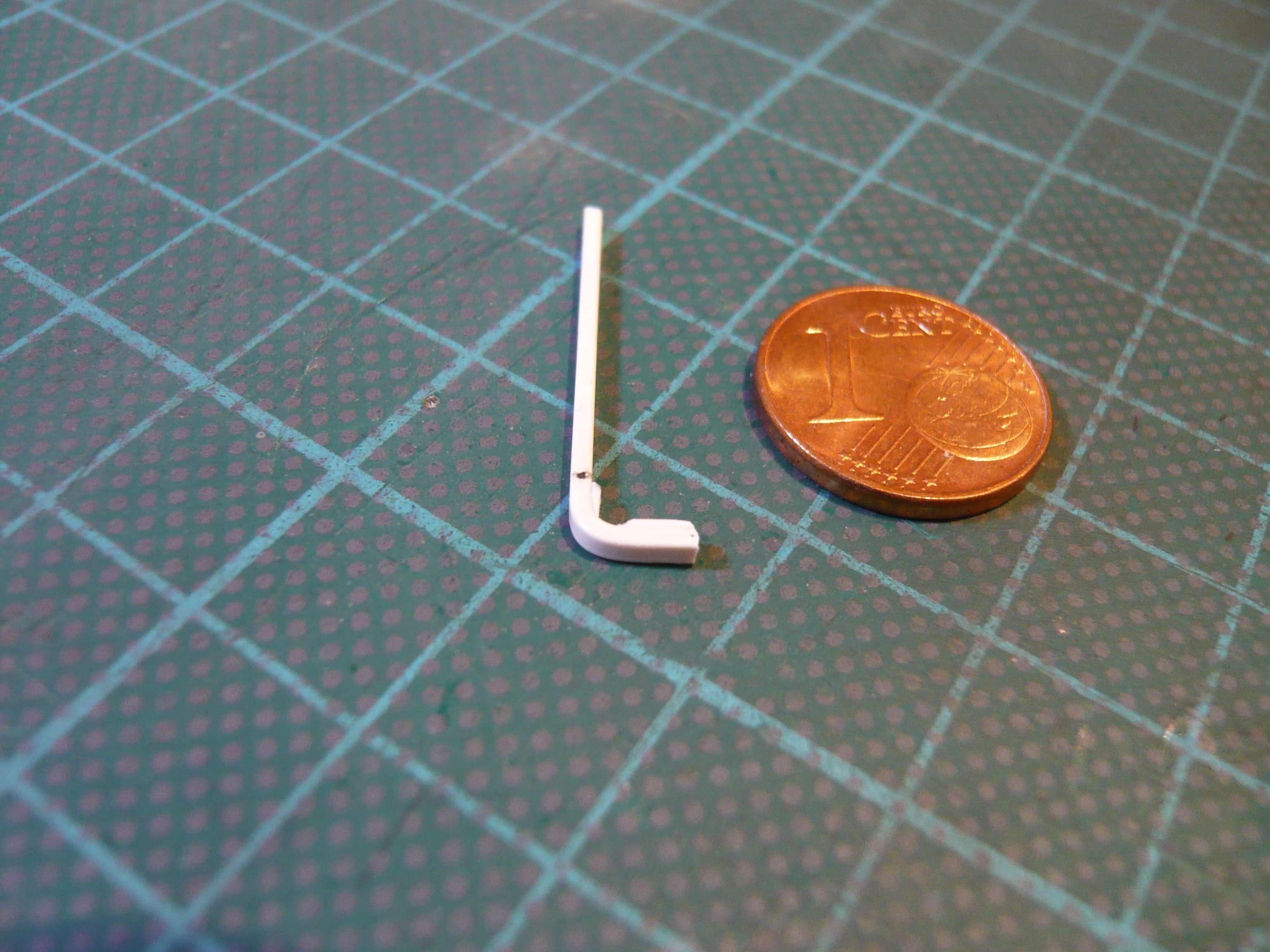
With it then I have checked the arrangement of the bow together with the center support (Part 2) and the provisional Part 3.4 for which I used a Profile bar (1,5 mm x 1,5 mm),
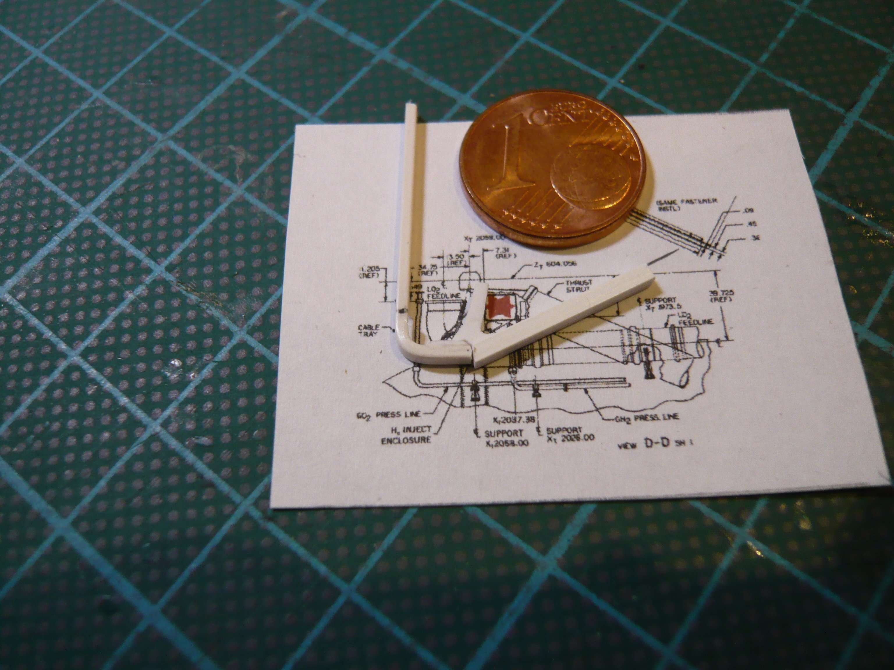
what already looked pretty neat.
Here’s for comparison the scale drawing of this arrangement,
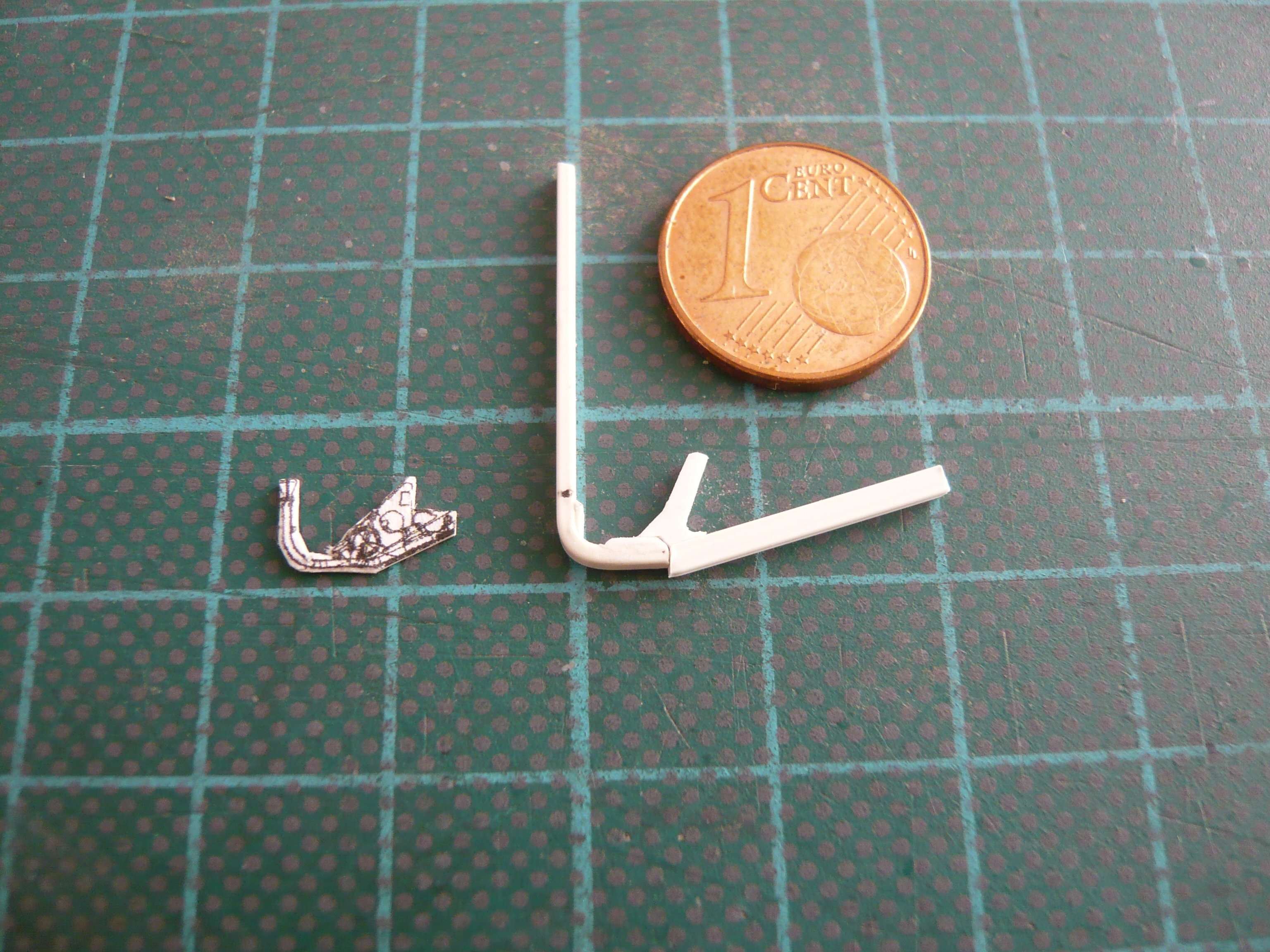
which I’ve provisionally laid on locally, in order to see if or how the size fits, which also looks quite well.
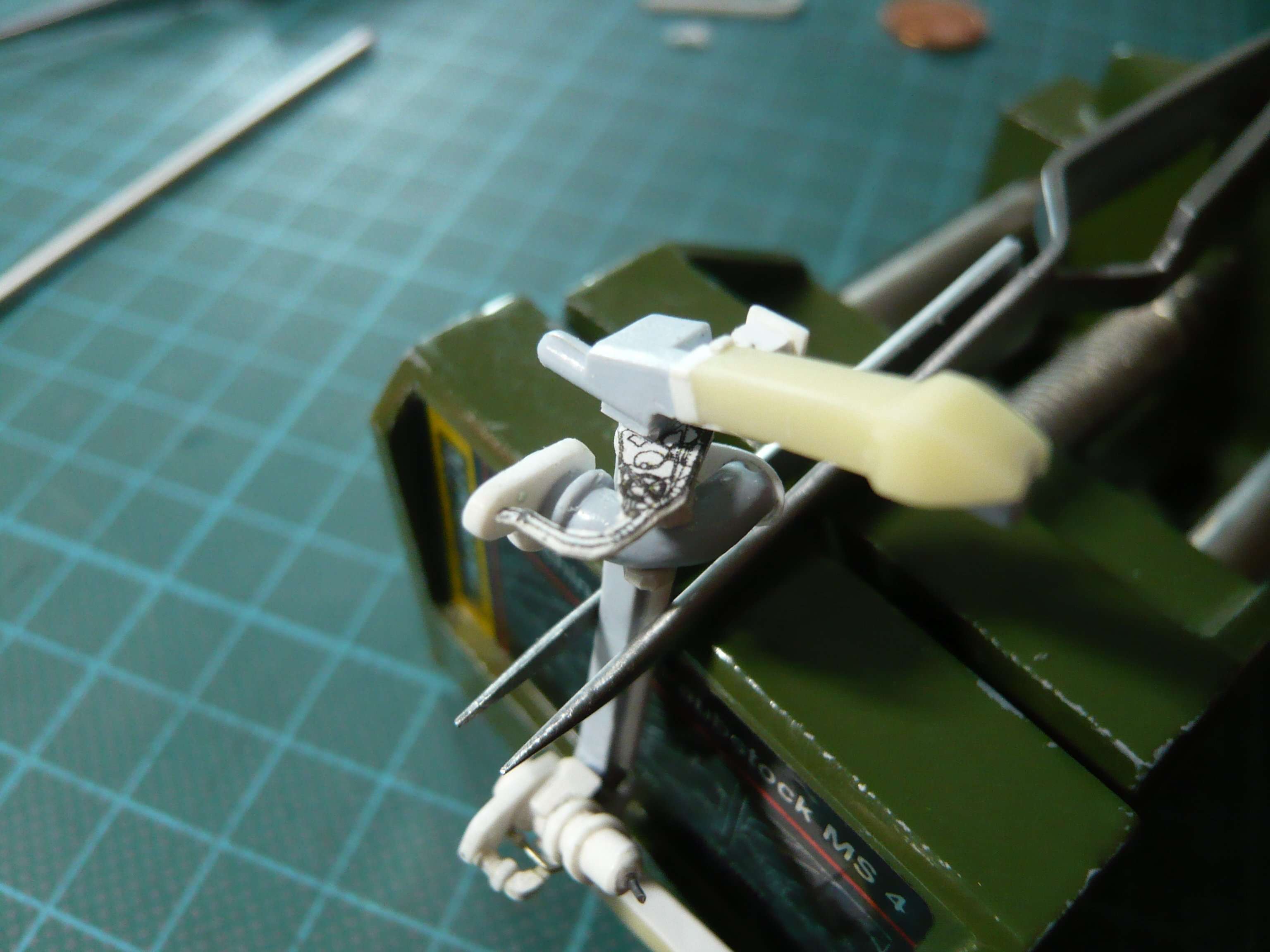
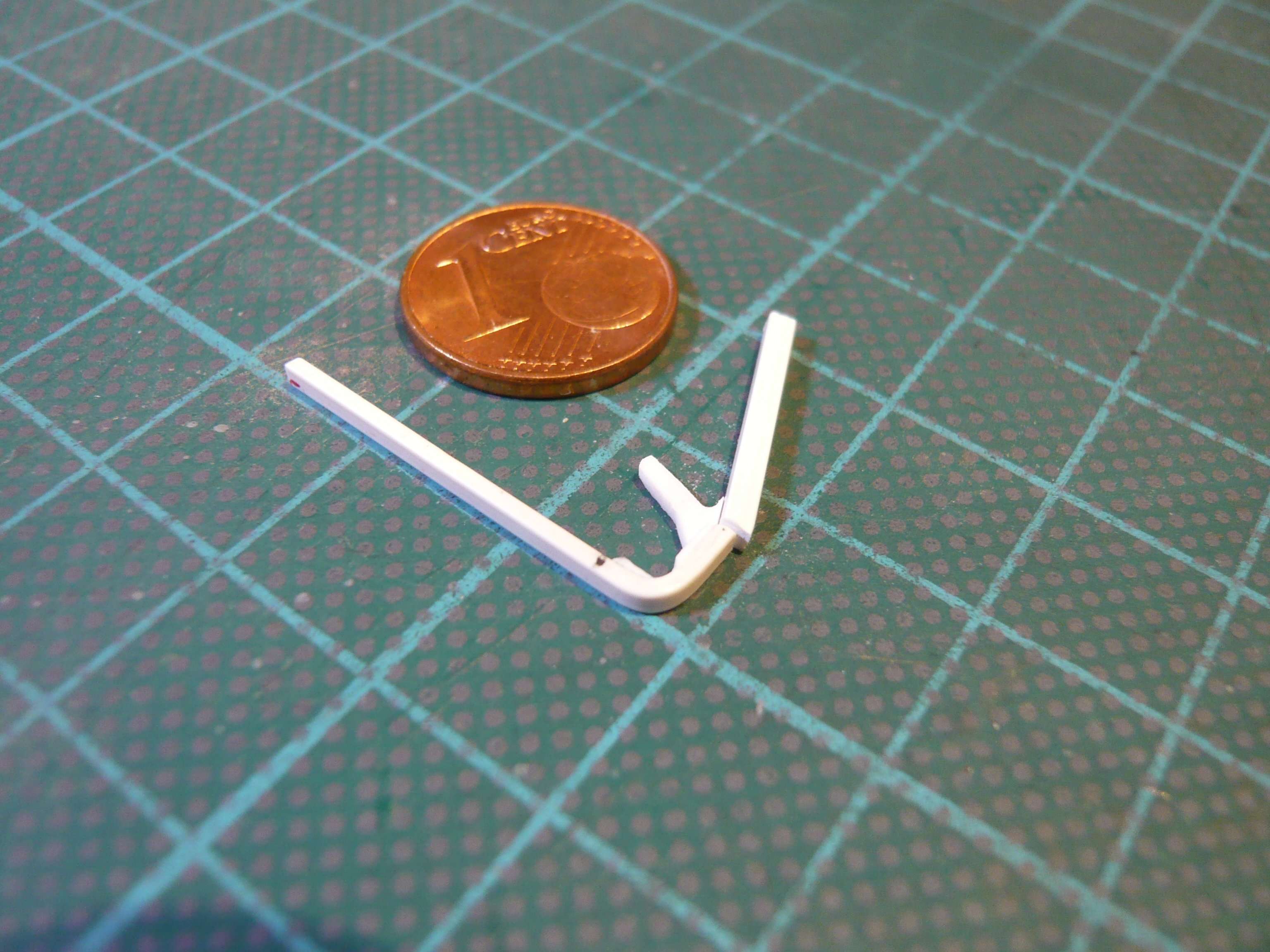
So far so good, but since with it neither the endpoint of the Cable Tray in front of the Crossbeam nor the length could be determined, I came up with the idea,  to bend a complete CT-Dummy out of a Strip (1,0 mm x 1,5 mm) and to test its location locally according to my previous measures.
After that was done in no time,
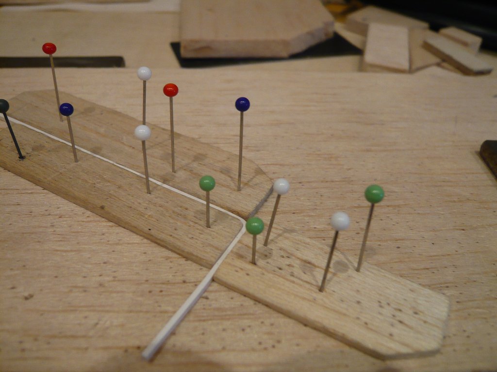
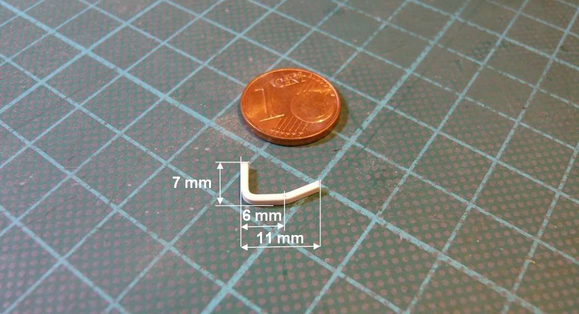
I’ve marked the height up to the Umbilical plate (about 7 mm), as well as the distance to the slant (6 mm),
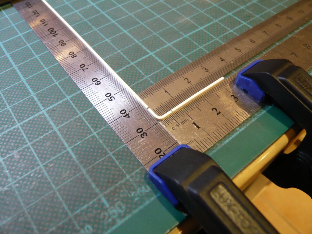
where I’ve bent it after the upper cut.
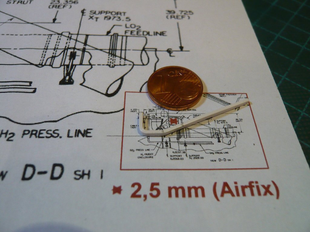
The length of the CT Dummy from the Crossbeam to the endpoint under the Umbilical plate I have measured with 11 mm. 
And then I’ve tried this dummy locally, whereby the positioning was a pretty tricky affair.
And as one can see, the part fits quite well,
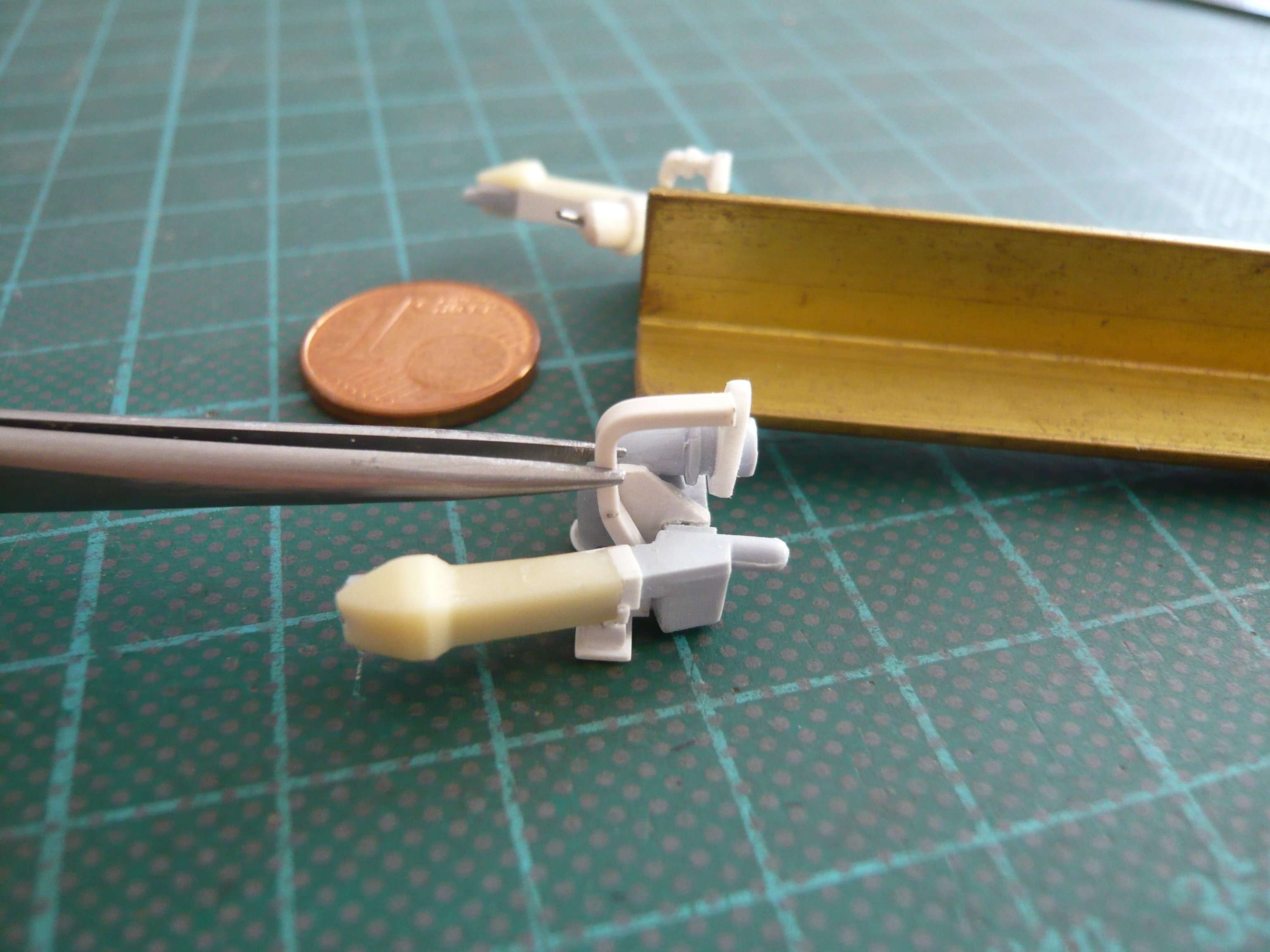
and hits roughly onto the slant of the LH2 Cable Tray below the Crossbeam, which seems quite plausible. 
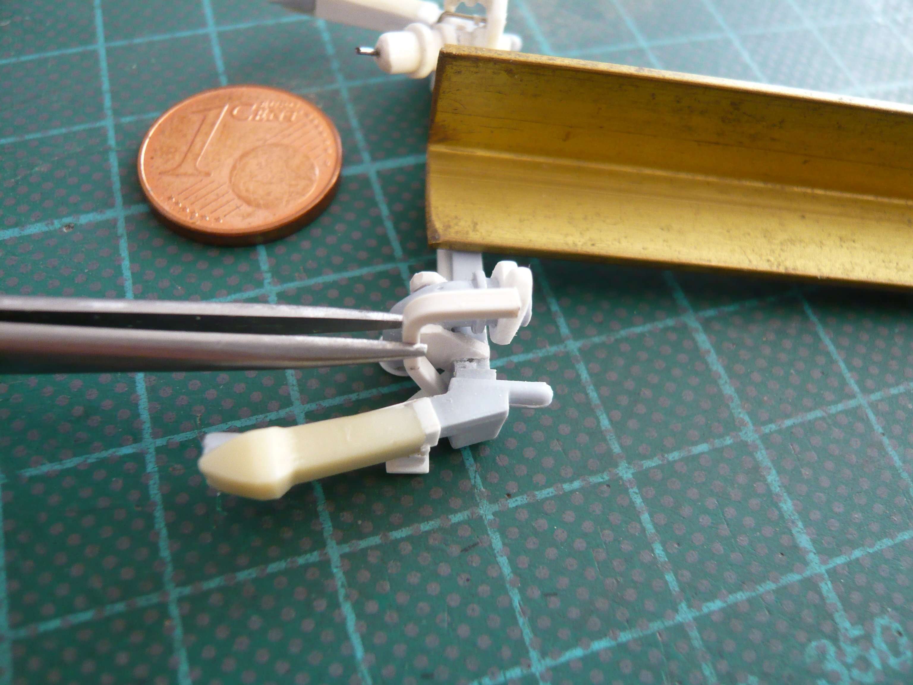
With these dimensions, I can now scratch the remaining parts on both sides of the previous bow.
That’s it for today.
Hello friends,
but with the attaching of further parts that’s another story, which is why I’ve thought of everything twice again plenty, especially since it is in the combination of such filigree parts not to millimeters, but rather by decimillimeters. And wether at the end the exact installation dimension of the Cable Tray would come out is more than doubtful, or but coincidence. 
Therefore, one does not get along without fitting, which is why it is better to proceed step by step, i.e. scratching one part at a time and preferring to test better safe than sorry to be able still to correct in between.
Thus, the CT-Dummy had done its duty and could be set aside.
But already with to try on the parts one has a lot of trouble to bring these small parts into position and then measure distances, what one can see in this image. Because in order to lay up the profile bar for the slant next to the central support, I had to put (with breath hold) a spacer in between. 

Therefore, it seemed appropriate to glue first the Center support (Part 2), so as to have a fixed point for the further procedure. Before that, I’ve placed the support several times on the outer LO2 Feedline Bracket and juggled back and forth, and finally made even smaller corrections (height/width) until I was satisfied with its position and then it could finally be glued.

Because if the size and location of this support would not be right, would not fit the slant, as well as the subsequent bow too.

And now, by laying on of the intended Profile bar (1,5 mm x 1,5 mm), I was able to more accurately determine the required length of the Slant (Part 3.4) than before, because the support could not slip anymore. But before I shorten the rod to the final length, I may be want to make a few minor modifications. At least the lower tip of the bar under the support should become still slightly bevelled.

In order to be able to adapt the bow with the lower Closeout to the support, I had to first shorten a bit the upper part of the bow in order to attach it to the Umbilical plate and to be able to test the position.
And also for this a special substructure was needed to get to the appropriate height. Above the black marking, it will then go on with the Parts 4-6.

But as one can see, the front part with the Closeout fits quite well under the support, so now still only the front slant has to be made to fit.
I am at a loss for words.
Welcome to the club, we’re going to make badges 
Simply stay tuned and enjoy, my friends, the show must go on.
Hello everybody,
well, this slanted front part of the Cable Tray(Part 3.4) really is a hard nut and has almost already become to a nightmare of my sleepless nights … 
But meanwhile I’m of the opinion that one edge more or less doesn’t matter, and therefore I will be content with an approximate solution, especially since later one cannot see this part under the orbiter from the outside anyway. 
The biggest difficulty in interpreting the course of the contours in the front area was this red circled notch directly under the Center support, which I have yet still decided to do,
which can be clearly seen again on this image section.
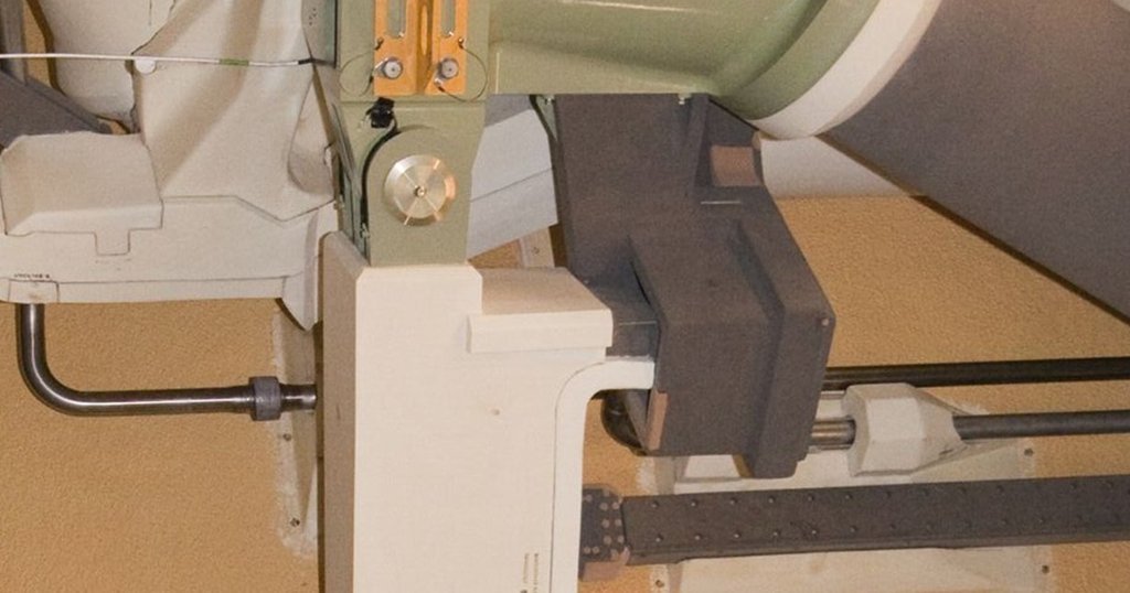
Source: forum.nasaspaceflight.com (DaveS)
And in this image one can also see the front area relatively well, where I will then orient myself during scratching,
especially since this is only a short stub of about 5 mm length anyway, as one can see here.

For the upper closeout, I’ve glued a Strip (0,25 mm x 1,5 mm x 3 mm),

and the lateral closeout will follow next in a similar way, wherewith I will then content myself.
Hello everybody,
in the meantime I have completed the remaining CT Parts (Parts 4-6) and glued the lateral edge onto the Slant (Part 3.4), that is made from Evergreen Sheet Styrene (0,13 mm), which is very thin but noticeably in contrast.
The upper Disk (Part 6) is the same size as on the other side Ø 2 mm x 0,3 mm, and for the Slant (Part 5) and the Plate (Part 4) I have each used an Evergreen strip (1 mm x 1,5 mm).

For gluing the disc on the slant, it was again fixed centrally between two steel rulers.


So far, so good.
Next, I actually wanted to glue the Slant (Part 3.4) under the Center support (Part 2). But before that I glued the two rings on the bow of the LO2 Feedline, which one can see in this photo.
For this I wrapped an Evergreen Strip (0,5 mm x 0,5 mm) around a steel rod and held it under the Hot air gun, then I’ve cut out two short segments, which were glued between the two Feedline Brackets, wherewith these details get done now too.

Then the slant was glued under the Center support, which extends to the LH2 Cable Tray under the Crossbeam. And that was also the expected delicate matter both for my eagle eyes (+ Headset magnifying glass), as well as for my quiet hand to place this part with the tweezers exactly as possible straightaway, what fortunately worked quite well.

After that I immediately tried on the bow and checked its position in the contact zone under the center support and to the slant, and corrected its position still minimally.


At the rear end of the slant now this CT-bow must be glued, as well as on it the remaining CT-Parts (Parts 4-6), which hopefully still fit in between.
Following that, I will then bend the end piece of the GO2 Press. Line also from a Nickel-silver rod (Ø 0,4 mm), which goes from the last Ice Frost Ramp up to the Umbilical plate, but for the time will being not glued. The remaining GO2 Press. Line forwards up to the LO2 Tank will then later be installed as a separate line.
That’s it for today, dear folks, and thanks for watching. 
Hello friends,
after the bow has fitted quite well, I then have glued it under the center support with the front slant and aligned immediately.


When trying on the upper assembly group Parts (4-6), I unfortunately had to realize that this was a bit too high and did not fit into the gap.  Therefore, the upper disc had to be removed again and the slant slightly shortened. After gluing a new disc, the group was then glued into the gap and also aligned.


Now I’m jolly glad that I also managed this tricky LO2 Umbilical, and am amazed that it come off quite well, as I think. And since it is quite similar to the original, the considerable effort was well worth it.
Next, as already announced, I will now bend and adjust the end fitting of the GO2 Press. Line.
Hello friends,
then I’ll continue with my pull-ups on the LO2 Umbilical. But before I’ll bend the end piece of the GO2 Press. Line, at first still to a last detail, which I wanted to leave out first, because I did not think it was that important.
And that’s this Bracket for guiding/stabilizing the Press. Line, which is mostly hidden on the photos and not completely visible,

Source: forum.nasaspaceflight.com (DaveS)
which is why I had to feel my way step by step, i.e. image by image.
In this photo one can see the oblique position on the inside of the Cable Tray, but otherwise one is groping in the dark.
Here one can see already in more detail that these are two thin narrow struts, which are connected at both ends,

[Source: forum.nasaspaceflight.com (Jester)()
what one can also see in this picture, from which I have determined the necessary dimensions.
On my first try, I glued Evergreen Strips (0,25 mm x 0,75 mm x 5 mm) together, using Strips (0,25 mm x 0,4 mm) as a spacer. But since the spacing for the Press. Line-Nickel silver rod (Ø 0,4 mm) seemed to be a bit too small,

I’ve adjusted it for the second try by gluing Strips (0,25 mm x 0,5 mm),


what comes already closer to the real conditions and looks better.

When test fitting the bracket, however, it turned out that it was a bit too long, since it should end at the height of the upper ring on the Feedline.

That’s why I’ve shortened it by one strip width (0,5 mm),

which looks more pleasing,

and above all fits better into the mould, and thus could be glued in this position by using MEK.

With that I can now bend the end piece of the GO2 Press. Line and its three Fittings, what should be a bit simpler than at the GH2 Press. Line on the other side, I hope at least.
Hello everybody,
so then to bending and installation of the end piece of the GO2 Press. Line.
First of all, it is necessary to know the preliminary end point of this gas line in order to be able to start bending, but this time it is relatively easy, since behind the last Ice Frost Ramp from the Newware Kit (R25) there are only two bends in the pipe.
Source: forum.nasaspaceflight.com (Jester)
That’s why I’ve used again my often shown ingenious Reference drawing from the recommendable ET Bible (System Definition Handbook SLWT - Lockheed Martin), from which one can take the exact location of the GO2 Press. Line (light blue) and of the GH2 Press. Line (red) direct next to the LO2 Feedline (dark blue).

Source: System Definition Handbook SLWT, Vol. II (Lockheed Martin)
And these three angles I’ve drawn into a 1:144 drawing of the ET cross section, and layed one of the 14 following Ramps (R23), in which both Press. Lines run up to the Intertank.
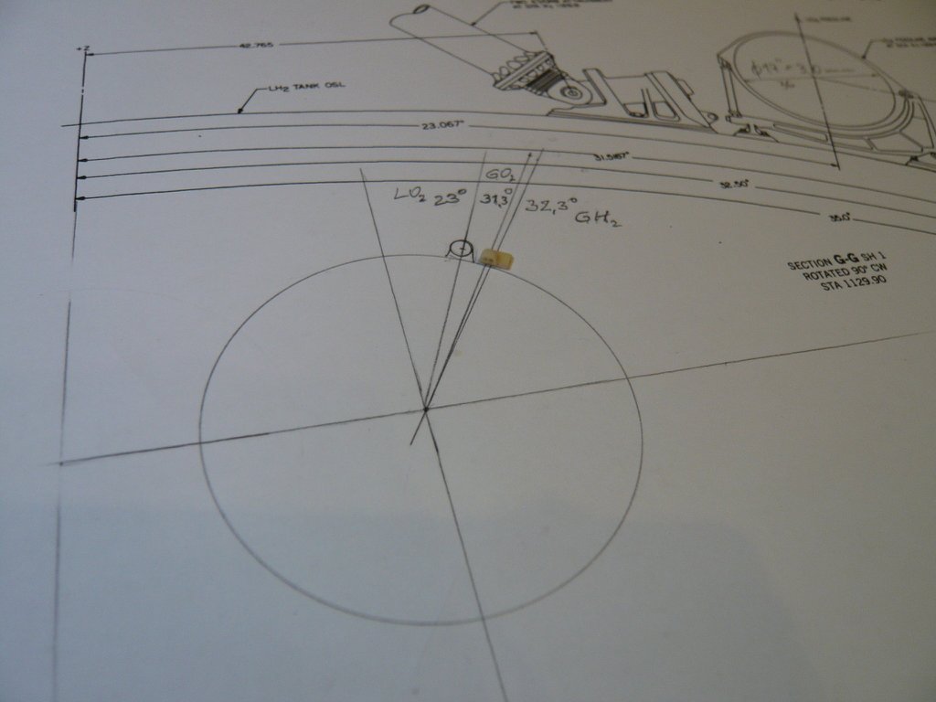
In this image, in front of it lays the last Ramp (R25), whose position next to the feedline is crucial for bending the GO2 Press. Line.
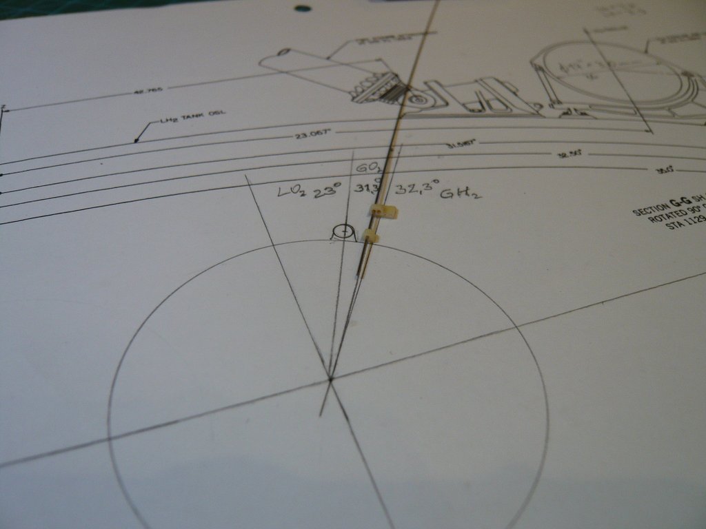
In order to determine their position as accurately as possible and to be able to transfer to the ET circumference, I have marked corresponding markings for all three lines on a Masking tape (1 mm).
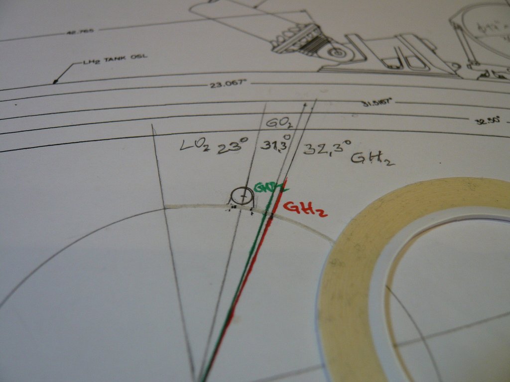
This tape I’ve glued onto the ET and then threaded a short piece of the Press. Line (Nickel silver Ø 0,4 mm) through the Umbilical plate and the Bracket, as well as provisionally layed a longer piece of the line onto the tank.
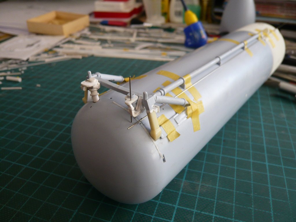
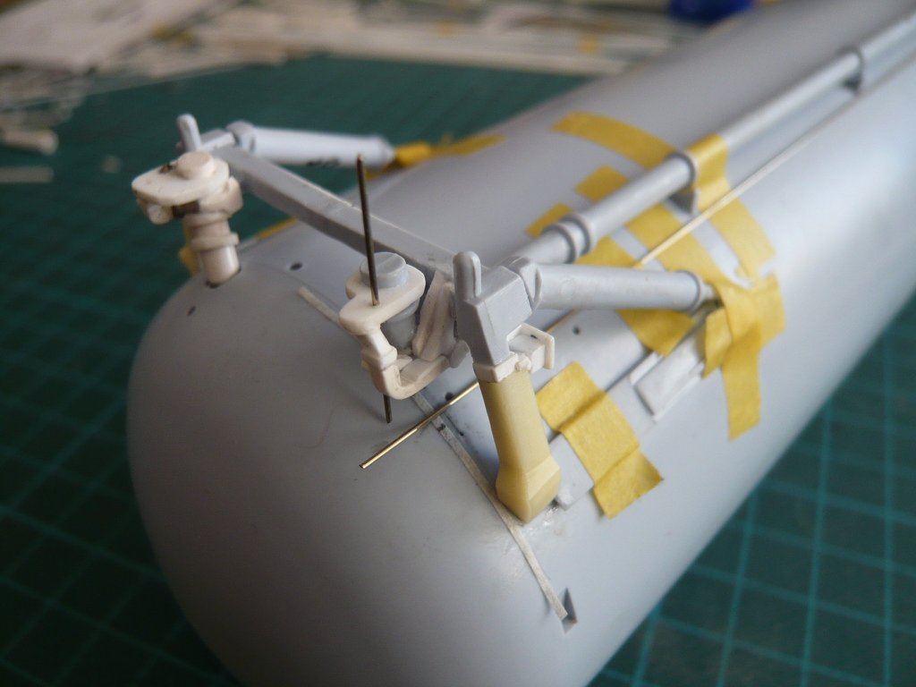
In order to be able to determine the distances of the lines from each other as well as from the last ramp as exactly as possible, I have threaded the Ramp R25, as well as four Ramps R23 to the front, and have fixed the line in this position with tape.
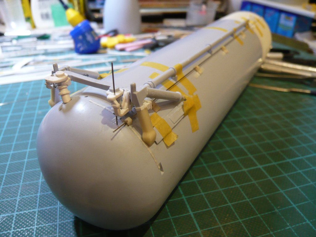
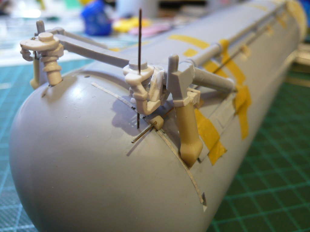
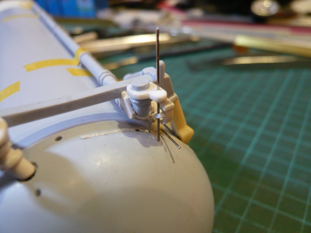
Afterwards the distance of both lines is approx. 2 mm, which agrees well with the distance determined from photos,
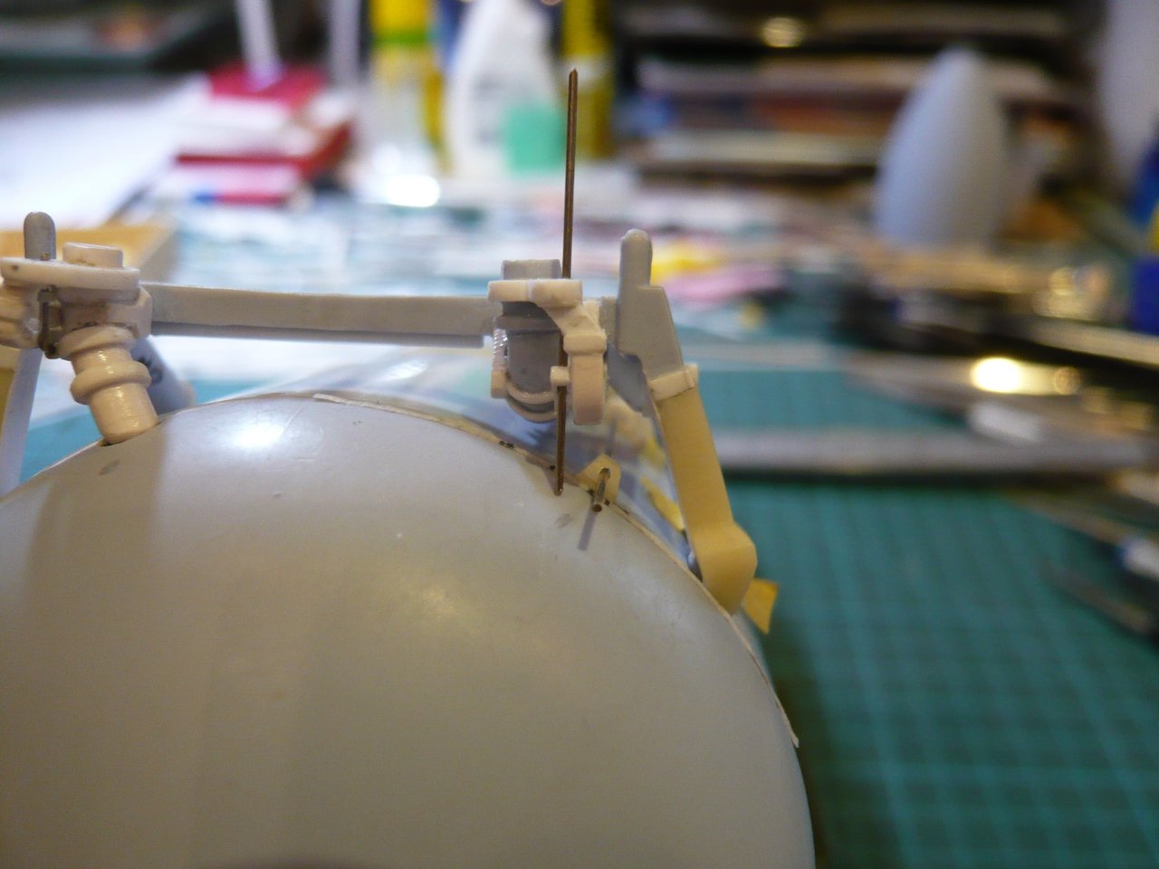
with which I could actually bend the short piece of the line.
But to relax the eyes stressed out by the macro shots is here a look from the normal viewer’s perspective.
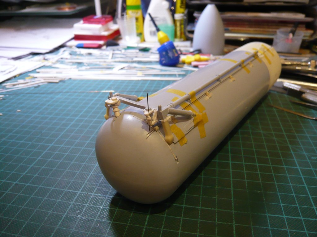
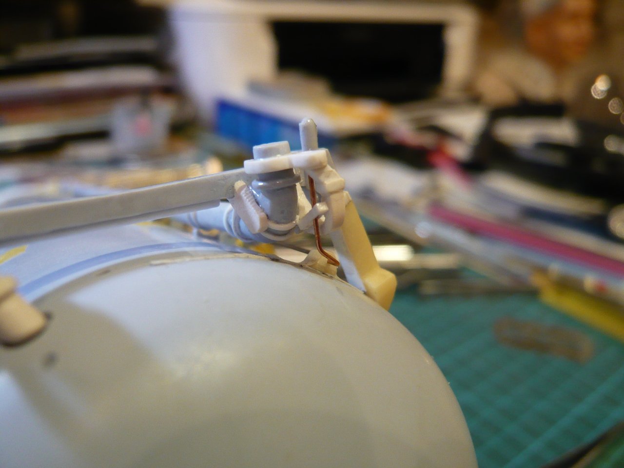
And since I was curious, I immediately made a first test-bending with a Copper dummy (Ø 0,4 mm), and as one can see here, the result looks already quite useful.
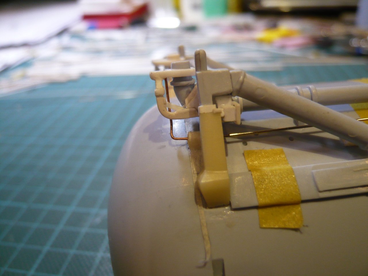
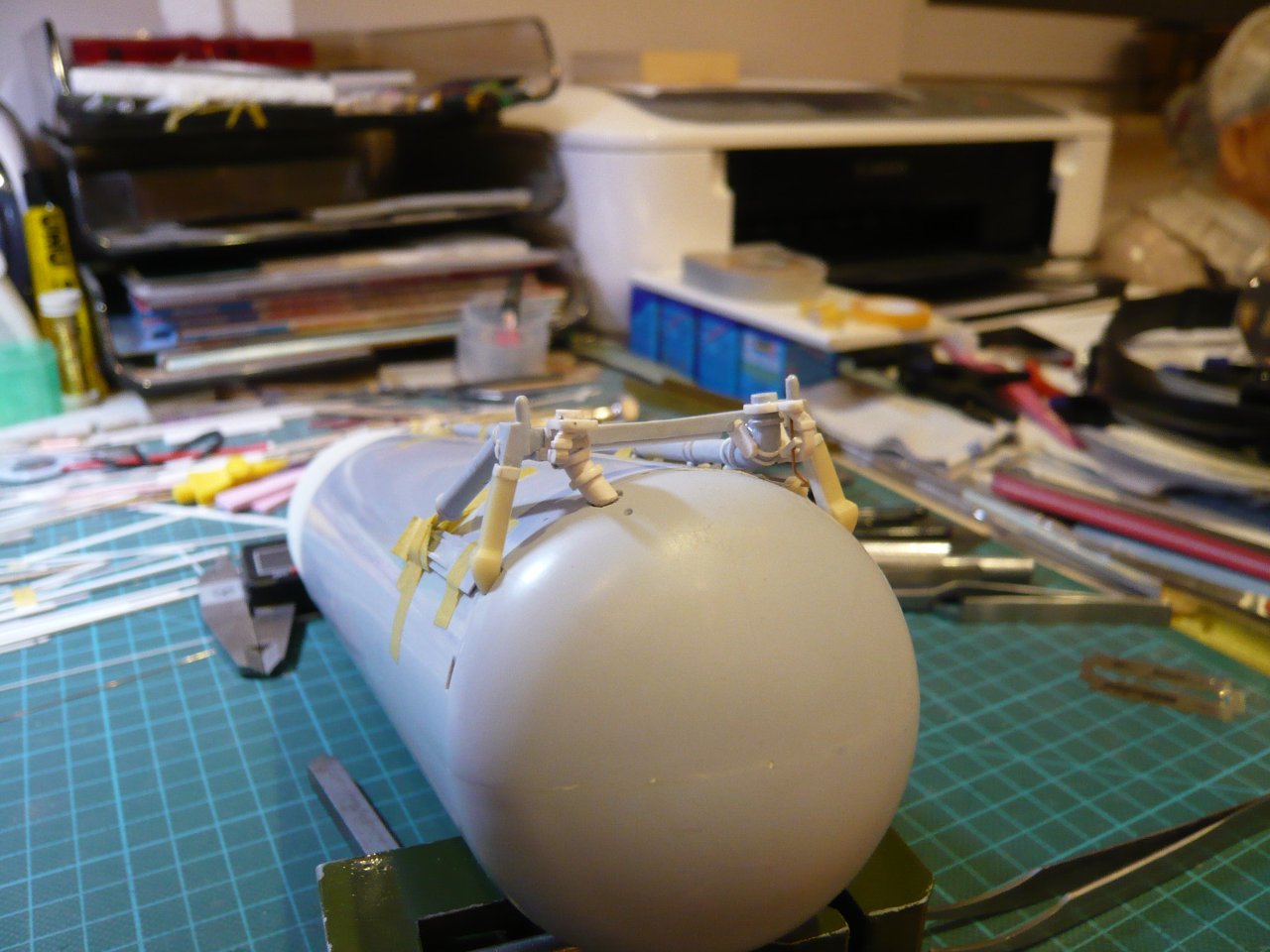
Similarly, I’ll now next bend the same line piece of Nickel silver (Ø 0,4 mm) and then also attach the three Fittings made of insulating tube, wherewith then the LO2 Umbilical would have been finished.
Hello friends,
today I have bent the end piece of the [GO2 Press. Line/color made of Nickel silver (Ø 0,4 mm). But as one can see, while bending the wire in the tweezers too sharp bends arise in comparison to the copper wire, which is much more flexible (ductile), what I did not particularly like.

That’s why I’ve used my round-nose pliers, and lo and behold, then therewith gentler curves succeed,

just as one can see it on this photo.
Then the test fitting on the Umbilical followed, which was expectedly tricky, because I had to thread the longer upper part of the wire first from below through the narrow Bracket and then had to insert it into the opening of the Umbilical plate.

Then I also still managed to insert the shorter piece in the rearmost Ramp (R25), in front of which the long GO2 Press. Line had been inserted.

Then I’ve also still cut the tiny Fittings from the thin Insulating hose (Ø 0,7 mm) in a known manner,

and have subsequently threaded the Press. Line, wherewith I am very satisfied for now.

But now the exciting question arises, how I should install this ringed end piece now best, since the upper ring cannot pass the narrow bracket?
Consequently, the ring must be removed before threading the wire in the holder and then re-fit without breaking off anything around. But how can one does it for heaven’s sake in this cramped space, especially since the normal threading is already absolutely stressful, and one has to take care hell-bent, that the tiny midget does not jump?
Therefore good advice is expensive, but maybe someone of you has a good idea that would help me?
In this sense, volunteers please step forward!
Put the bottom two on first, then the last one, the upper one, after threading it through the bracket… Then insert it into the Rearmost Ramp…
Only way I can see to do it…
EG
Thanks Elmer for your nice proposals.
My previous skepticism regarding the threading of the ring on the Press. Line was based on my up to now realized Mounting perspective.
But then I came up with the idea to simply reverse the perspective and turn the Attachment upside down.
With that, the Umbilical plate lays below, and the ring would not fall down immediately, if one handle it carefully enough to place it over the opening.
And that’s exactly what I did. First, I threaded the two lower rings in front of and behind the bend, and then introduced the line from above through the Bracket.
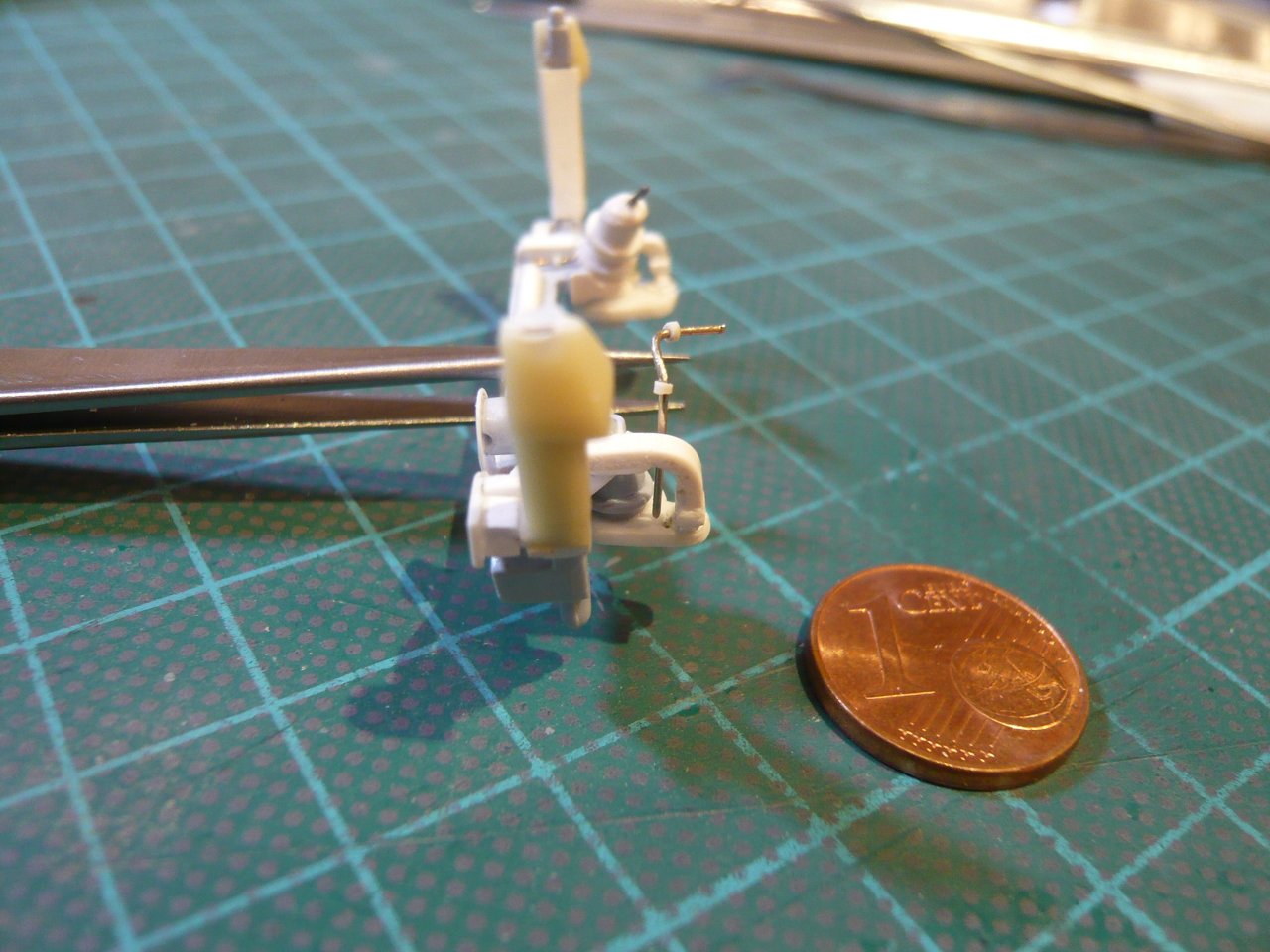
Then I threaded the upper ring onto a very thin Insect needle (Ø 0,25 mm) and inserted it next to the Bracket into the opening of the Plate.
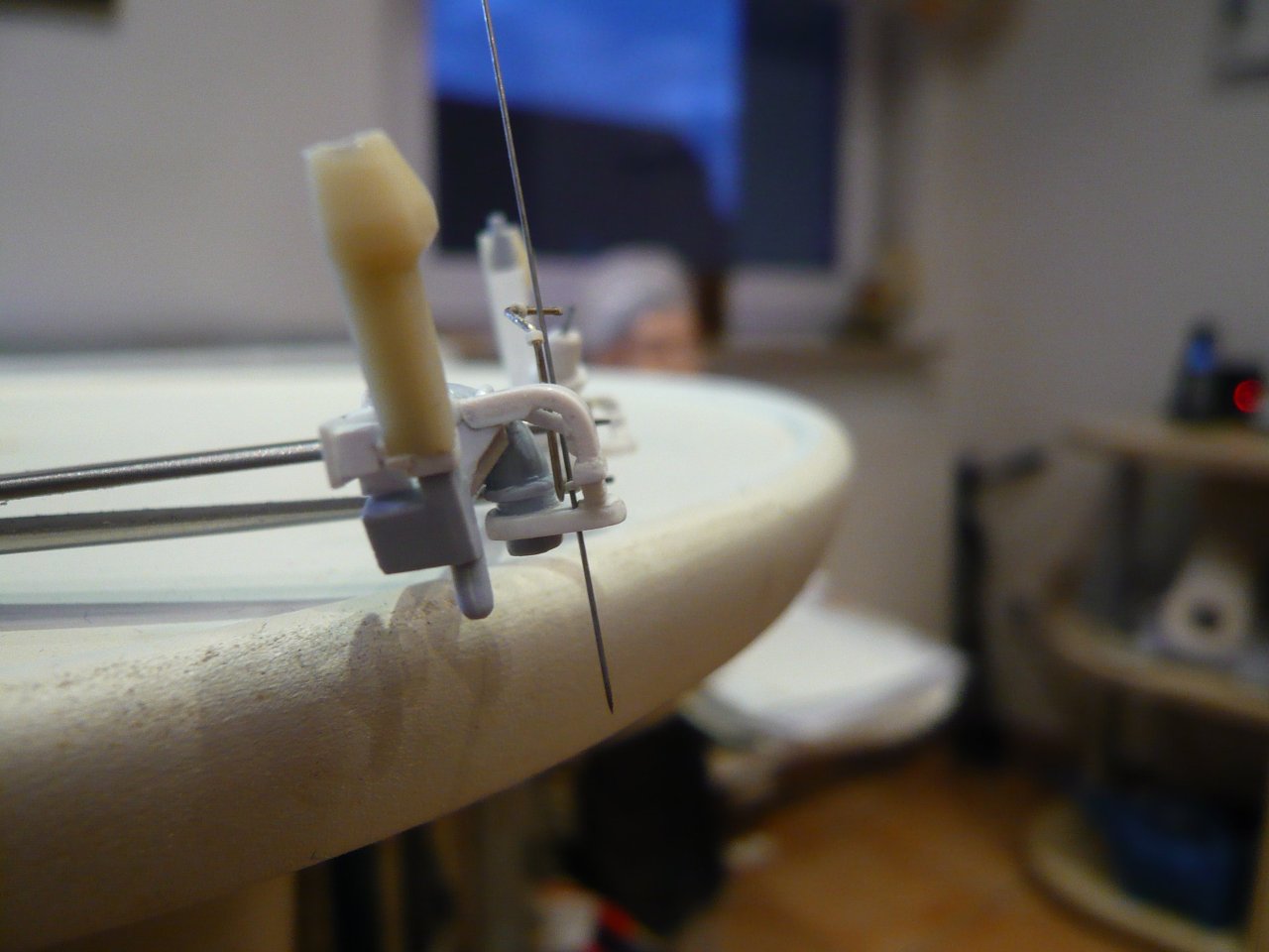
Then I carefully pushed the ring with the cutter tip to the plate and pulled out the needle very slowly, so that the ring came to lie directly on the opening.
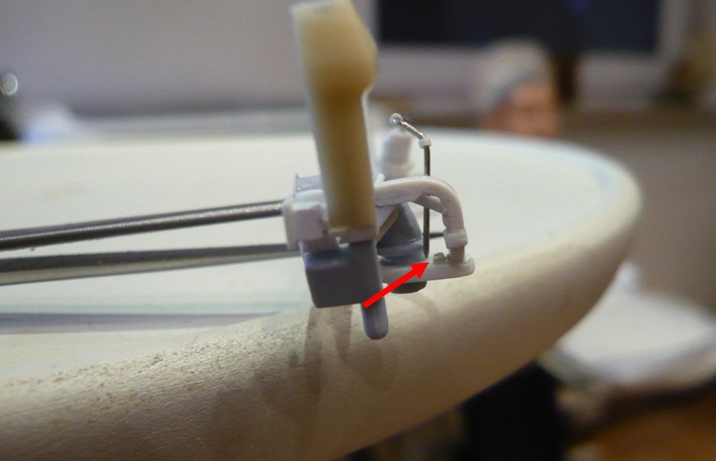
And then I held my breath and gently inserted the slightly sharpened line with the tweezer through the ring into the opening until the point under the plate appeared, with which my stunt was indeed successful. 
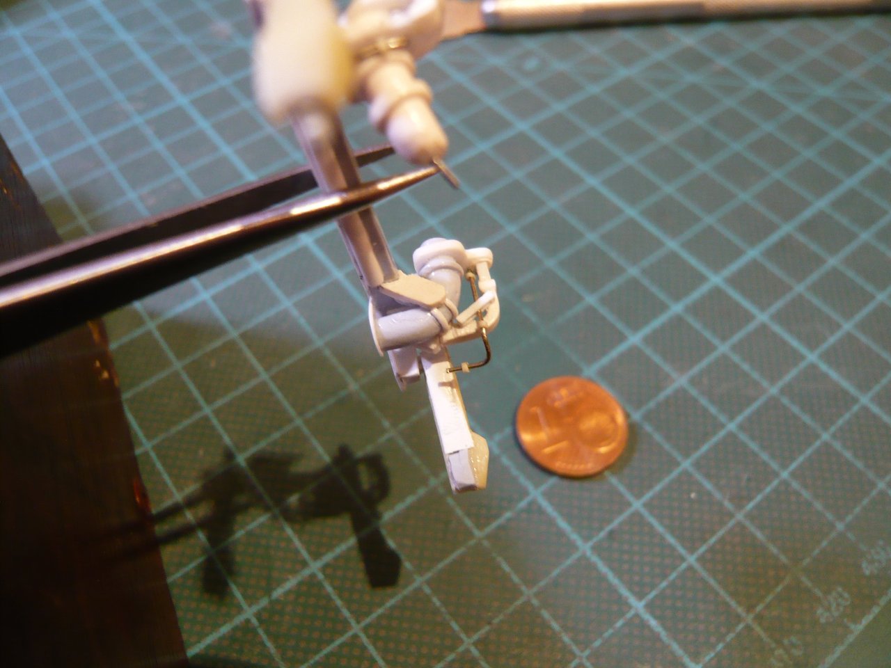
And this is how the Attachment on the ET looks from both sides.
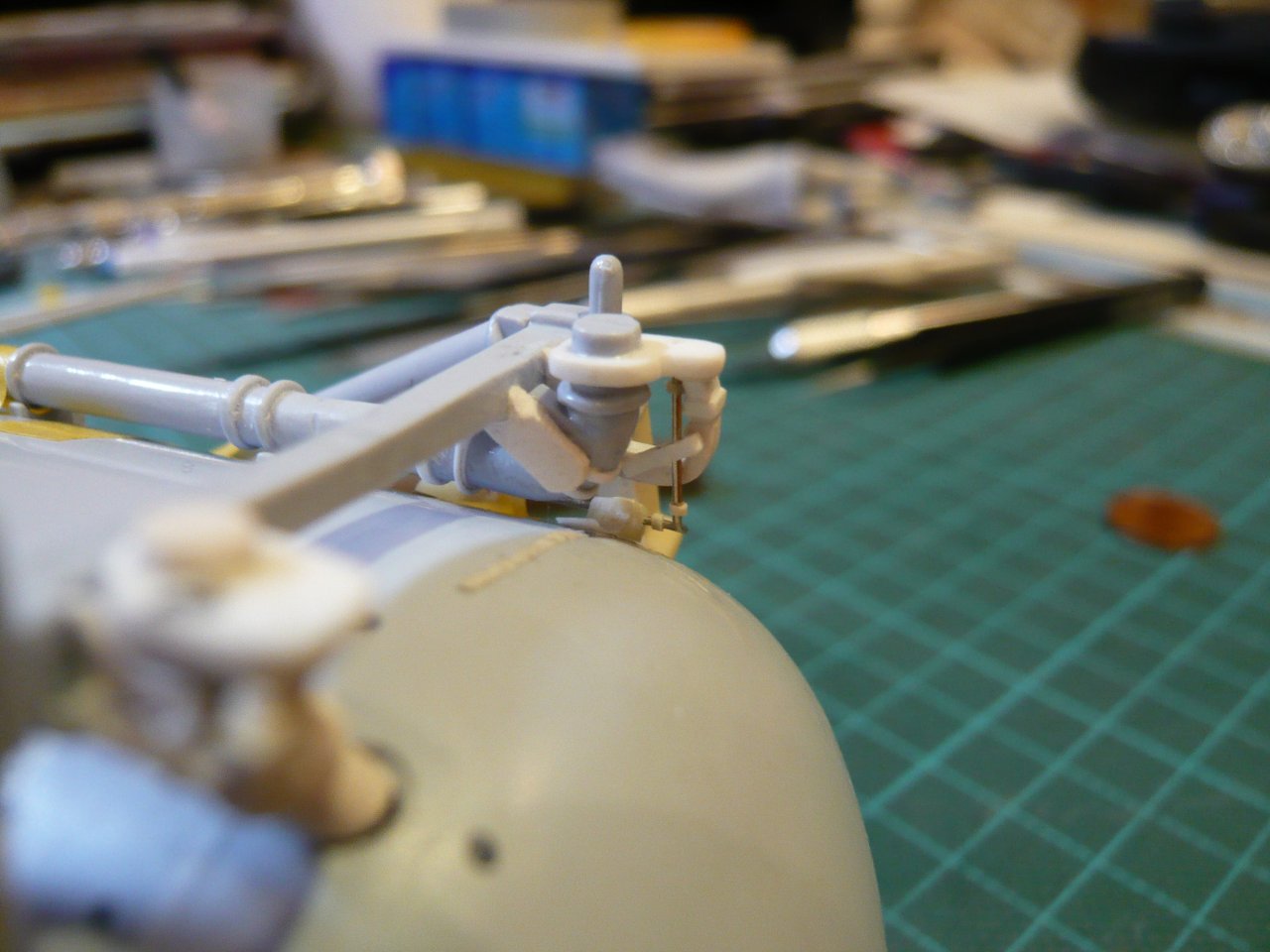
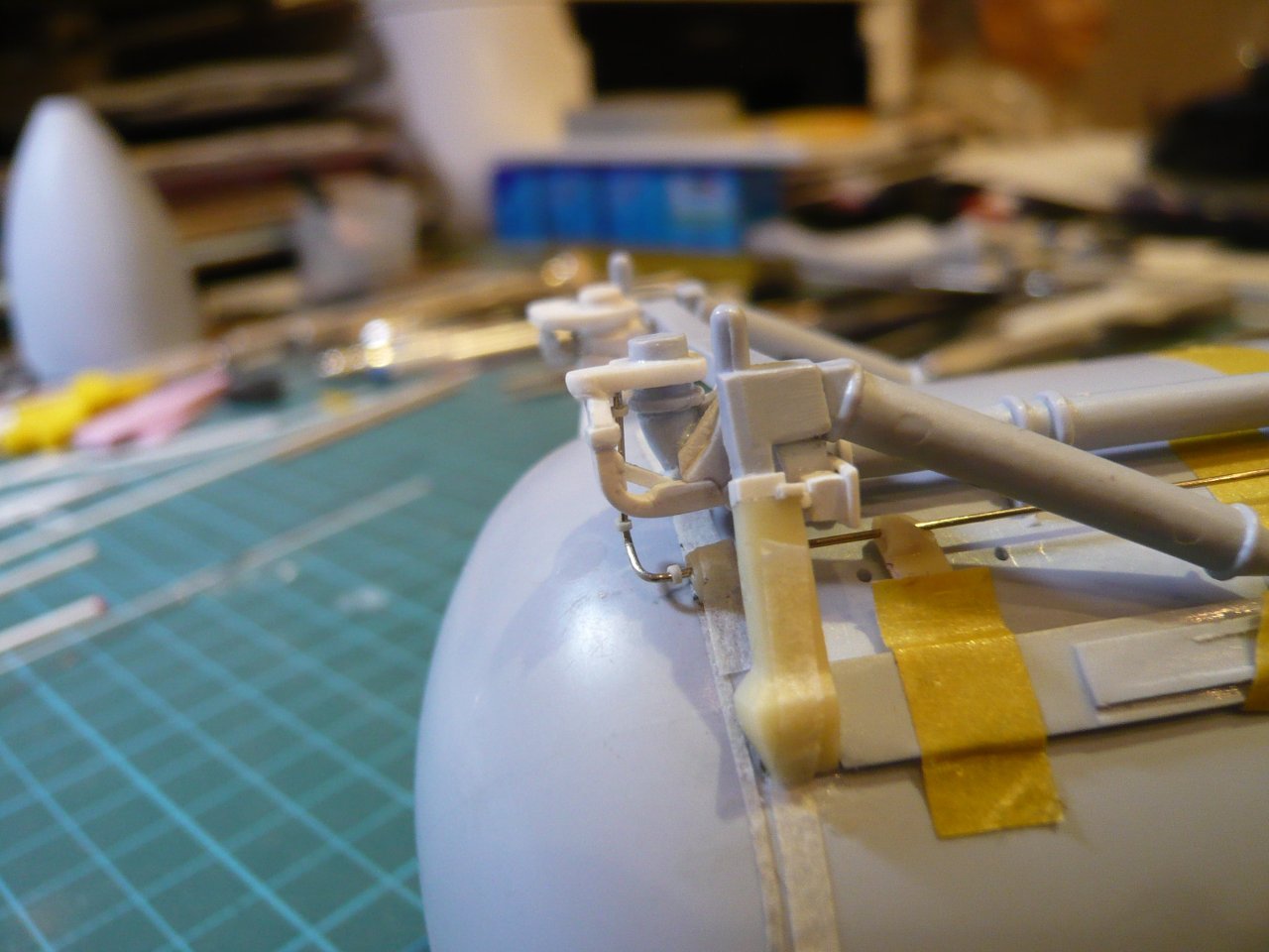
Now the Press. line can still be aligned a bit and glued in this position in the Umbilical plate and with the Bracket, whereby it would then finally fixed.
And now I can make a nap for a short time …
Hello everybody,
and after the end piece of the GO2 Press. Line now to the end piece of the GH2 Press. Line, which directly lies next to it and after two bendings runs slantwise upwards in the direction of Crossbeam, as one can see on this image.
With this line I want to proceed the same as with the GO2 Press. Line and initially only bend its end piece from the last Ice Frost Ramp (R24) to the TPS cladding under the Crossbeam, because the continuation of the line on the LH2 Tank until the Fairing on the Intertank should also be installed separately.
In the following image I have used a Steel rod (Ø 0,4mm) for the GH2 Press. Line and threaded it into the back three Resin ramps from the Newware Kit (NW 131).
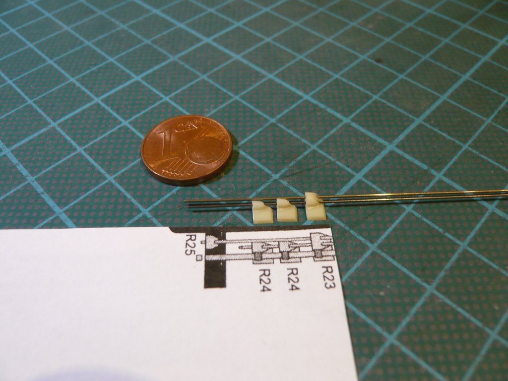
On this photo one can see an Original ramp with the two Press. Lines, as well as the LH2 Cable Tray runnig below.
And already as forward look and for the sake of completeness, in the following image are to see the 17 Ice Frost Ramps on the LH2 Tank , whereby the Ramps 1-14 (R23) are “Double”-Ramps (see previous photo).
The connection point of this line piece at the TPS cladding under the Crossbeam can be seen in the following photos.
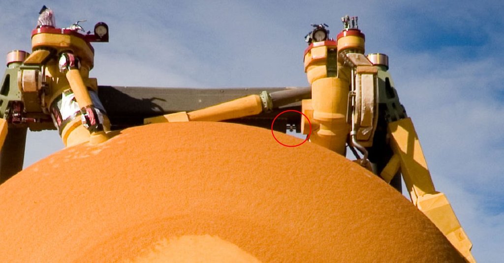
Source: forum.nasaspaceflight.com (Jester)
In this photo one can see in the zoom that in front of the Fitting in front of the TPS cladding also still a small Support is sitting.

Source: forum.nasaspaceflight.com (DDG40)
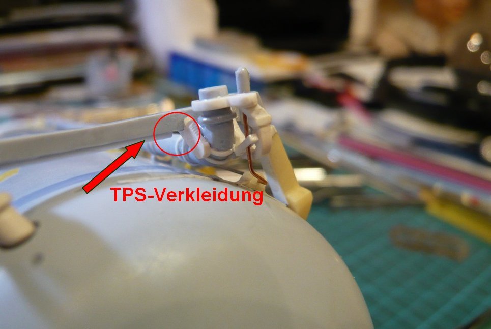
And that is this point here on the model, which has unfortunately proved to be too low with detailed review and measurement of the gap to the LO2 Feedline Bracket, which is why I had to shorten the TPS cladding very carefully a little bit with a razor blade to create the required space for the little Support.
And these are the required separates. The small Support I’ve cut off from the rest of the TPS cladding, in front of it lies the tiny Fitting made of Insulating hose, and in front of them the Cu dummy for the end piece of the Press. Line (Ø 0,4 mm).
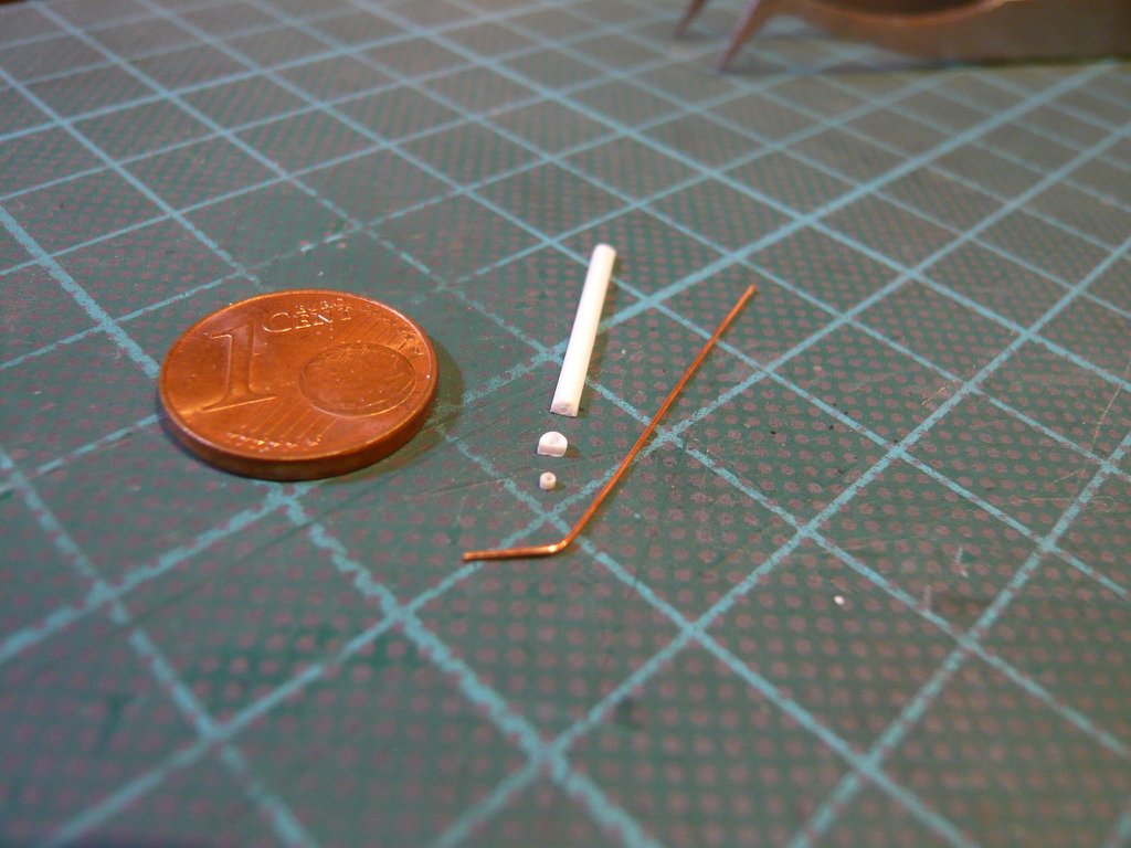
And the test fitting of the Press. Line looks already rather well. 
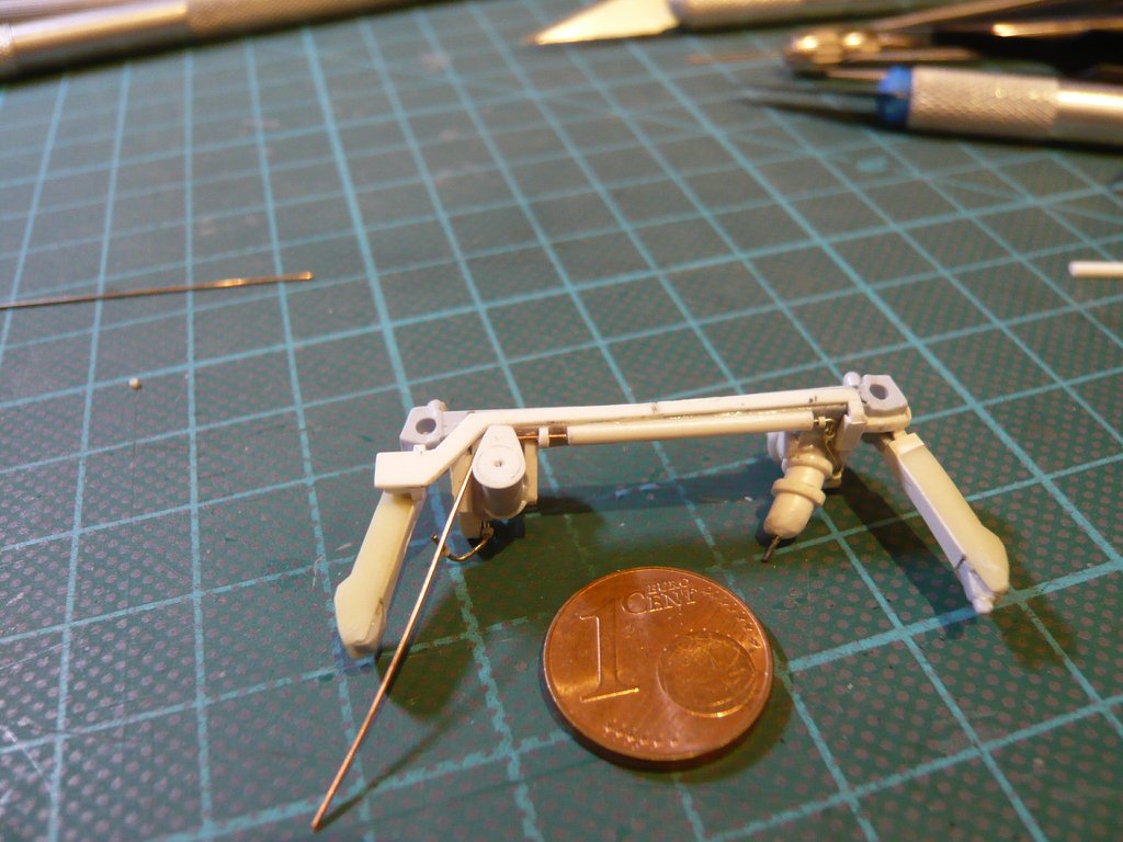
But with that I was again faced with the same problem of threading the tiny Fitting in the space of this gap …
But meanwhile I have some practice with it, and that’s why I have prepared this time again a small Toothpick-Tape holder, as at that time in a similar action at the SSWS on the MLP,
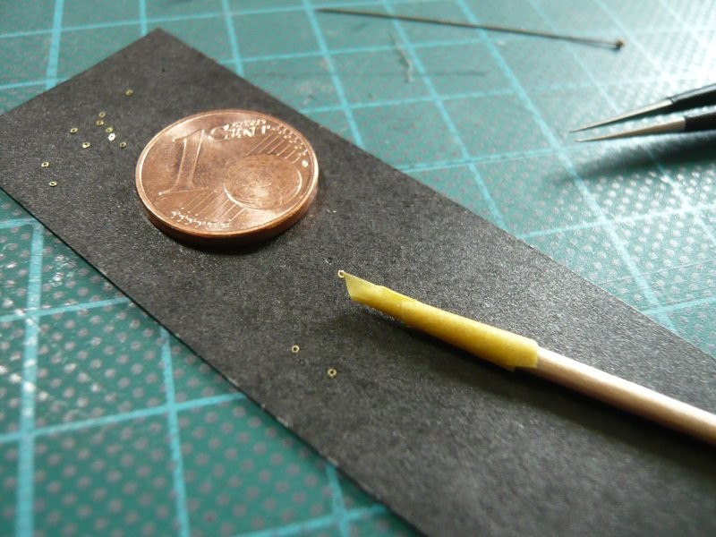
at its top of which this time the Fitting hung.
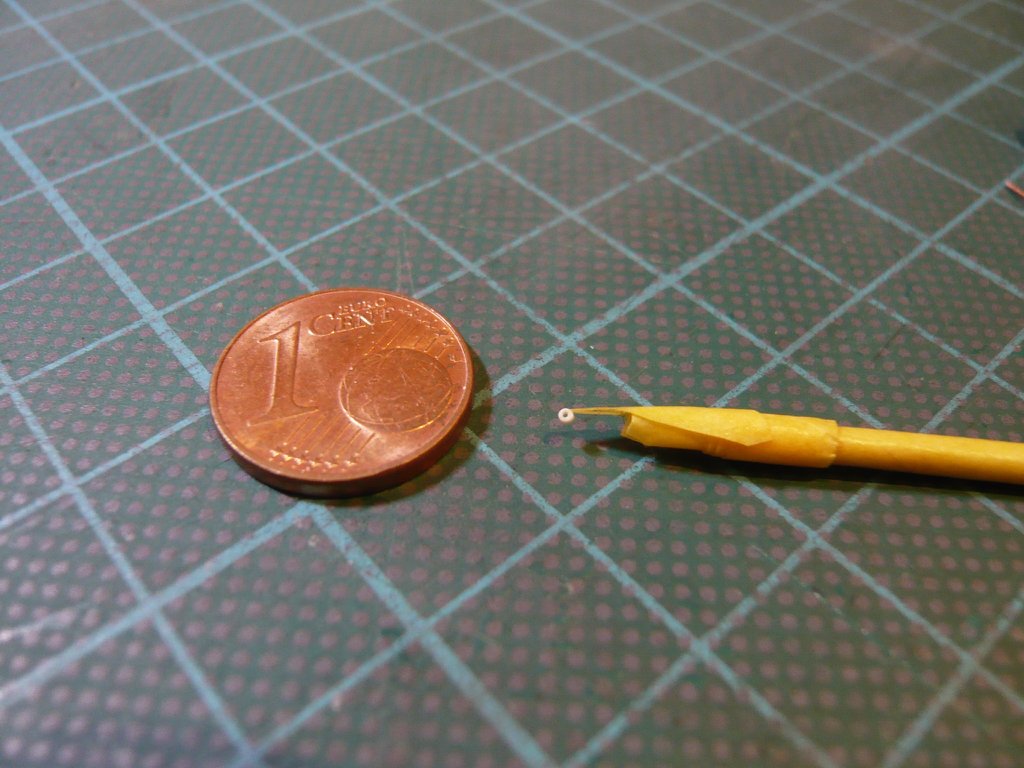
The threading was again a similarly stressful and shaky matter with held breath as at the GO2 Press. Line, but ultimately I was successfully again, as one can see.

Now I can put the Attachment back onto the ET and determine the length of the Press. Line up to the lower two bendings in front of the rear Ice Ramp (R24), which can then be bent.