SS 249 Flasher in 1/72 (Revell Gato Kit)

image

I’ll take that.
Now I just need to scratch the main induction valve:

My previous assertion that the larger pipe is 36 inches was not correct. I was relying on my memory of a somewhat incorrect sketch of the system - one in which the pipe was labeled as 36" in one spot, but 22" in another. The actual body of the main indduction valve should have been labeled 36".
I discovered this rather quickly when I tried putting a piece of half inch tubing (36" in scale) underneath the decking and above my pressure hull, and it just looked too large even though it fit. Fortunately I have several sizes of tubing , as shown above, and everything looks right now, Scaling out the 22" and 16" pipe, mine now comes as close as the various sizes made by Evergreen will allow. The one above with the reinforcing rings is the 16".
I can still use the half inch tubing for the main induction valve. I just have to remember where in my spares I’ve seen something that looks just like that umbrella hoop.

I just remembered seeing this in my searches. The accuracy of something occupying the same physical space as a bulkhead, a la the Philadelphia Experiment, is a little sus[ect, however…

9 Likes

And now I’ve discovered what the nightmare project device is, and it’s not, as I first suspected, a cross between a wood chipper and a log burner, :wink:.

That is one heck of an amazing build 18b, certainly going to be following this further, and hopefully find out your rivet solution at the same time, :slightly_smiling_face:…a truly outstanding build, :+1: :slightly_smiling_face:.

G, :beer:

Thank you. I continue to fight the good fight.
I haven’t smoother out the cuts yet. Not even necessar6y really, but I don’t want even a hint of sloppiness to show under the PE.

But today I have to take a break from building for a very special meeting. More later.

8 Likes

Time to shift gears again, only because a package arrived today.

I continue to search for appropriate vehicles for this diorama. I don’t want to put anything on there "just “because.” I was lamenting about how it’s a shame I can’t use anything from Airfix’s WWII USAAF BOMBER RE-SUPPLY SET. I have two of the sets. I thought perhaps I could use the Autocar U-7144 tractor with a scratchbuilt trailer, similar to the other one I’ve almost completed, but once again I find no evidence that the Navy ever used it, and the Army was not likely to have one in Fremantle.
Similarly the Chevrolet M6 bomb truck and trailer are unusable. Or are they?
Could the trailer have been converted to haul torpedos? My plan to scratchbuilt three of those little torpedo carts was weak - they don’t have pneumatic tires, and pushing them along the quay by hand didn’t seem likely. My search to discover if the M6 Chevy could be used led to a surprising new discovery - the Ford M1 Bomb Service Truck, used by the Navy.
image
Things were looking up. But could the trailer be converted? Again grasping at straws, when I found that the Navy had already thought of that as well. Here is a trailer with bombs. Getting closer…
image
And then:
image
Yes! Proof that the tractor trailer combo was used for torpedos.
But they’re not submarine torpedos. Turns out the cradles are adjustable on the trailer crossmembers. And that indeed -


The Mk3 Mod 1 trailer can in fact be used for Mk XIV torpedos. And if it can handle a Mk XIV it can handle a Mk XVIII.

Now the trick is to kit bash the Chevy M6 tractor

with my latest postal delivery

Then I’ll scratchbuid the trailers. More as that develops…

10 Likes

How about an Autocar being used on Bougainville by the RNZAF who normally received their aircraft & vehicles thru the USN FotoWeb

1 Like

I’d love to use the Autocar and tanker from the Airfix set, but there’s no plausible way to show it. It would have no reason to be on the quay - not even for refueling. Gatos required an enormous amount of fuel, and that would have been handled by the sub tenders, the USS Euryale in this case. I’ll use my tanker in another dio. Actually, probably two taners behind one tractor, leaving me with another tractor to pull a scratchbuilt trailer.

1 Like

I may have to get another Bomber Re-supply set.
I spent some time looking for other ways the cab from their M6 Chevy could be used - to no avail.
But I was looking for the wrong thing. It turns out that International M-2-4 could fairly easily be built from it - and it was used by the Navy. :thinking:

I looks almost as if I could add a bed and a winch to the bomb truck. The toughest part might be adding more louvers.

I think it’s quite feasible to have a contingent of Marines guarding the second largest Allied submarine base in the world. Mount a .50 in the back - throw some Jarheads in it.

3 Likes

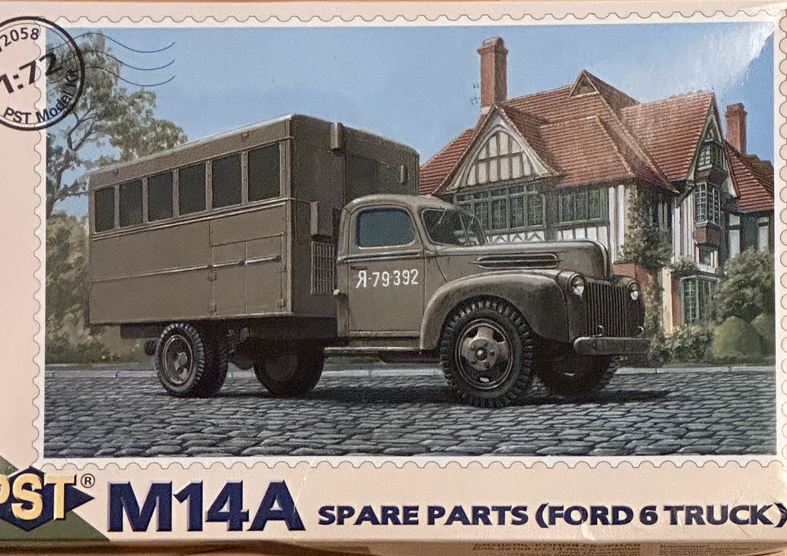
My decision to build the M1 Bomb Truck using the Ford truck and the Chevy M6 Bomb truck has led to what the Army likes to call “second and third order effects.”

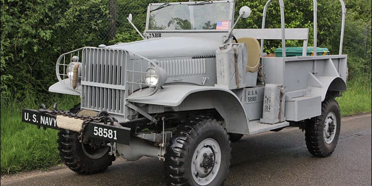
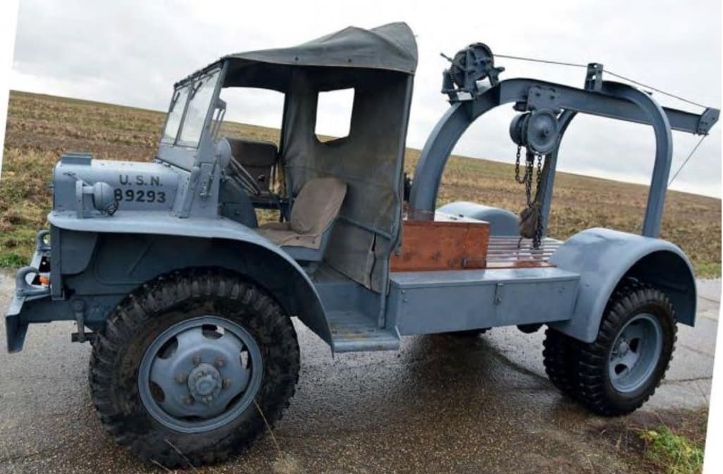
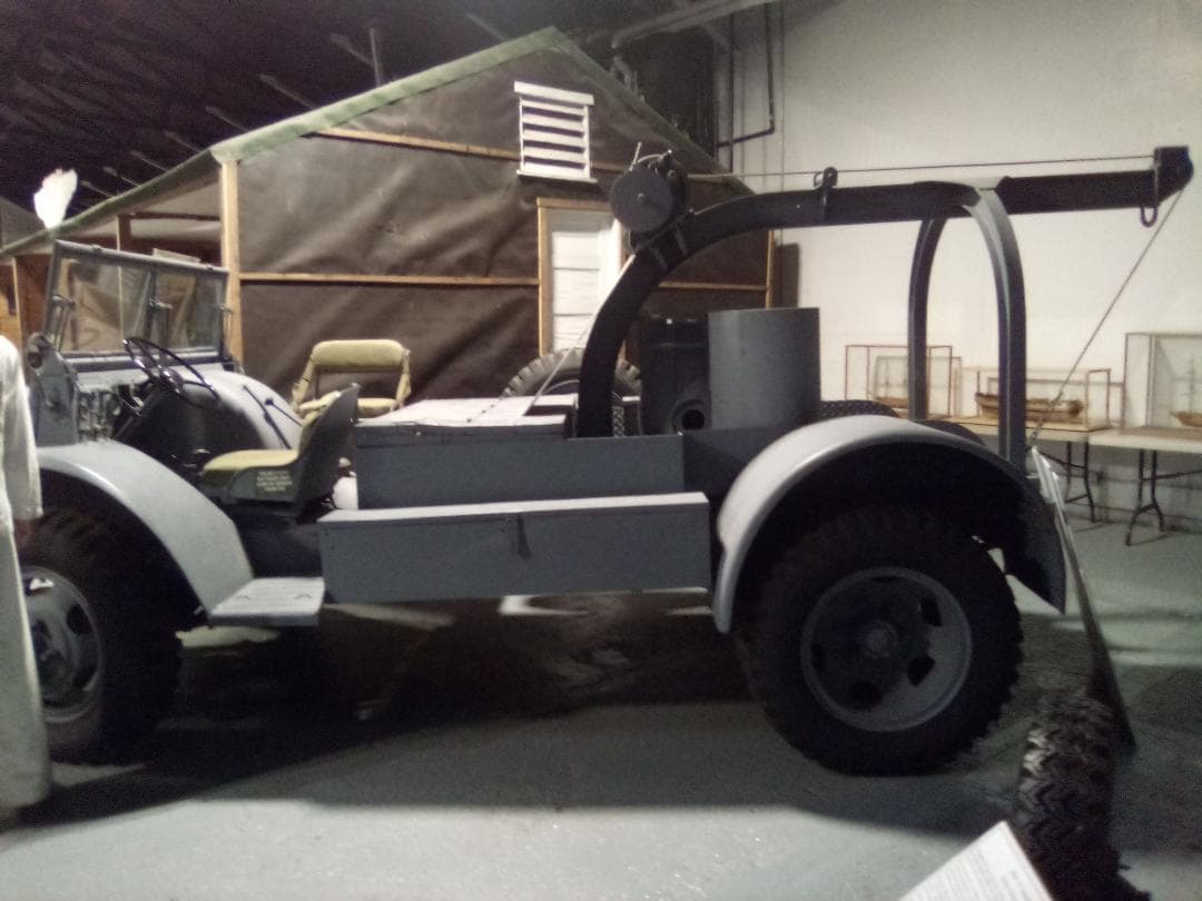
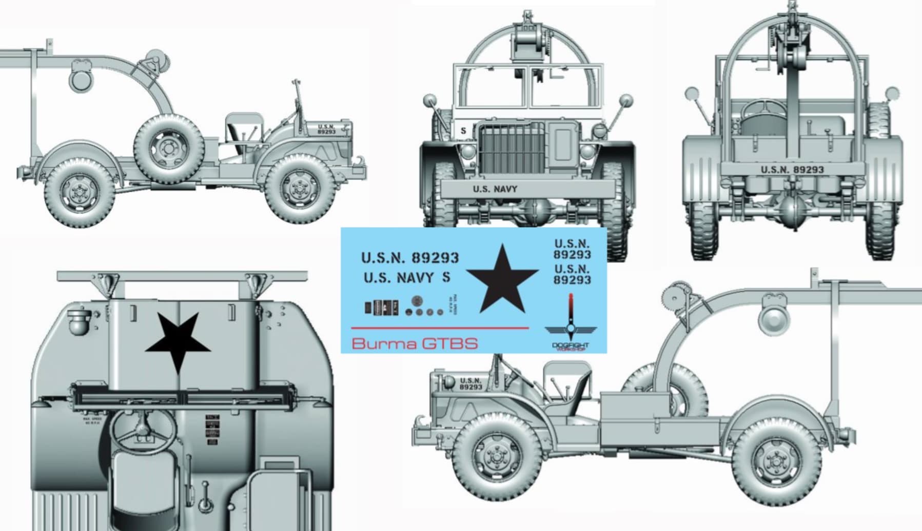
The first thing I discovered is that the Navy, unlike the Army Air Corps, did not feel that four wheel drive was necessary for airfield duty. An odd decision given some of the conditions and locations of Navy airfields in the Pacific. So the whereas the M6 Bomb Truck has four wheel drive, the M1 does not:

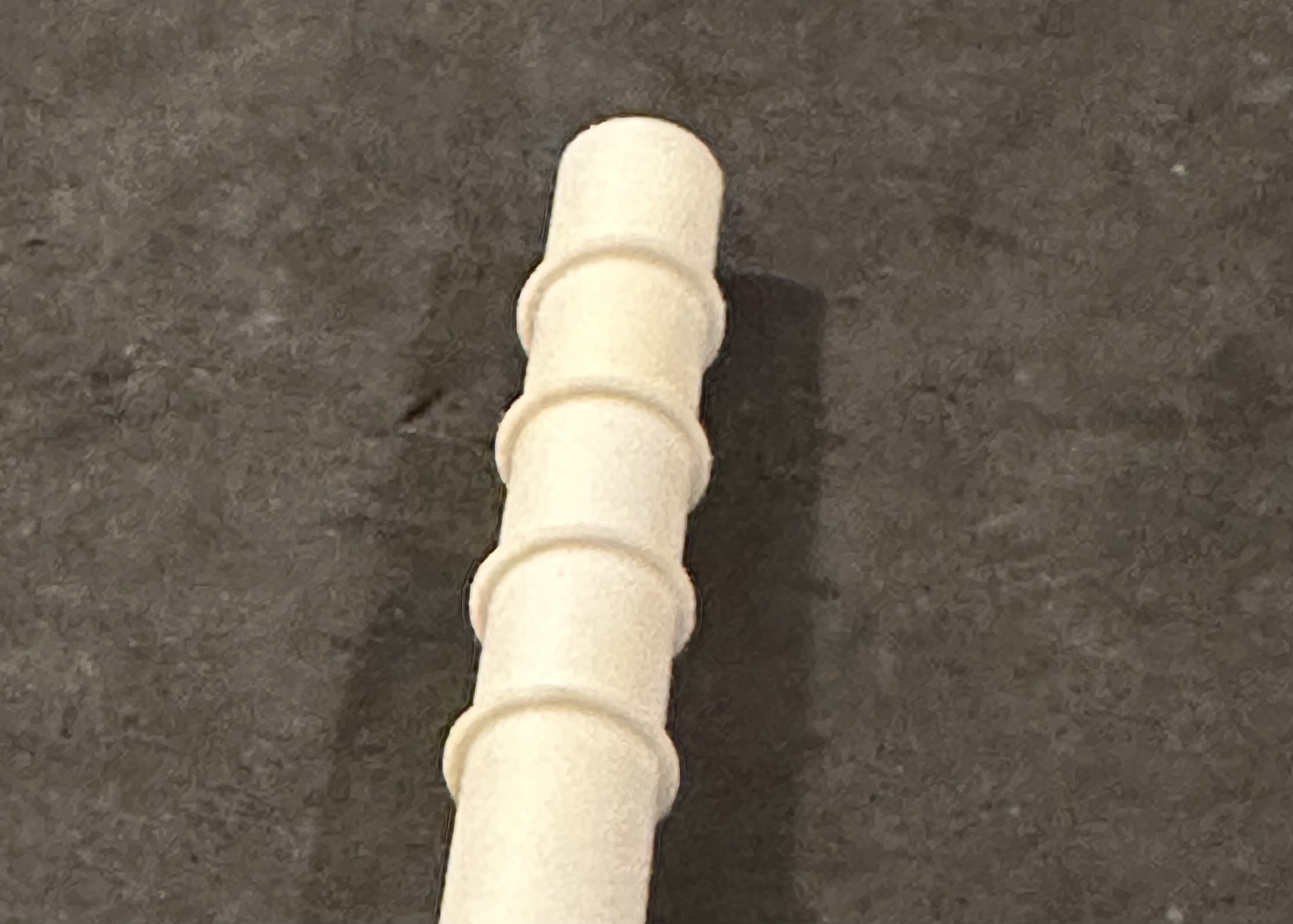
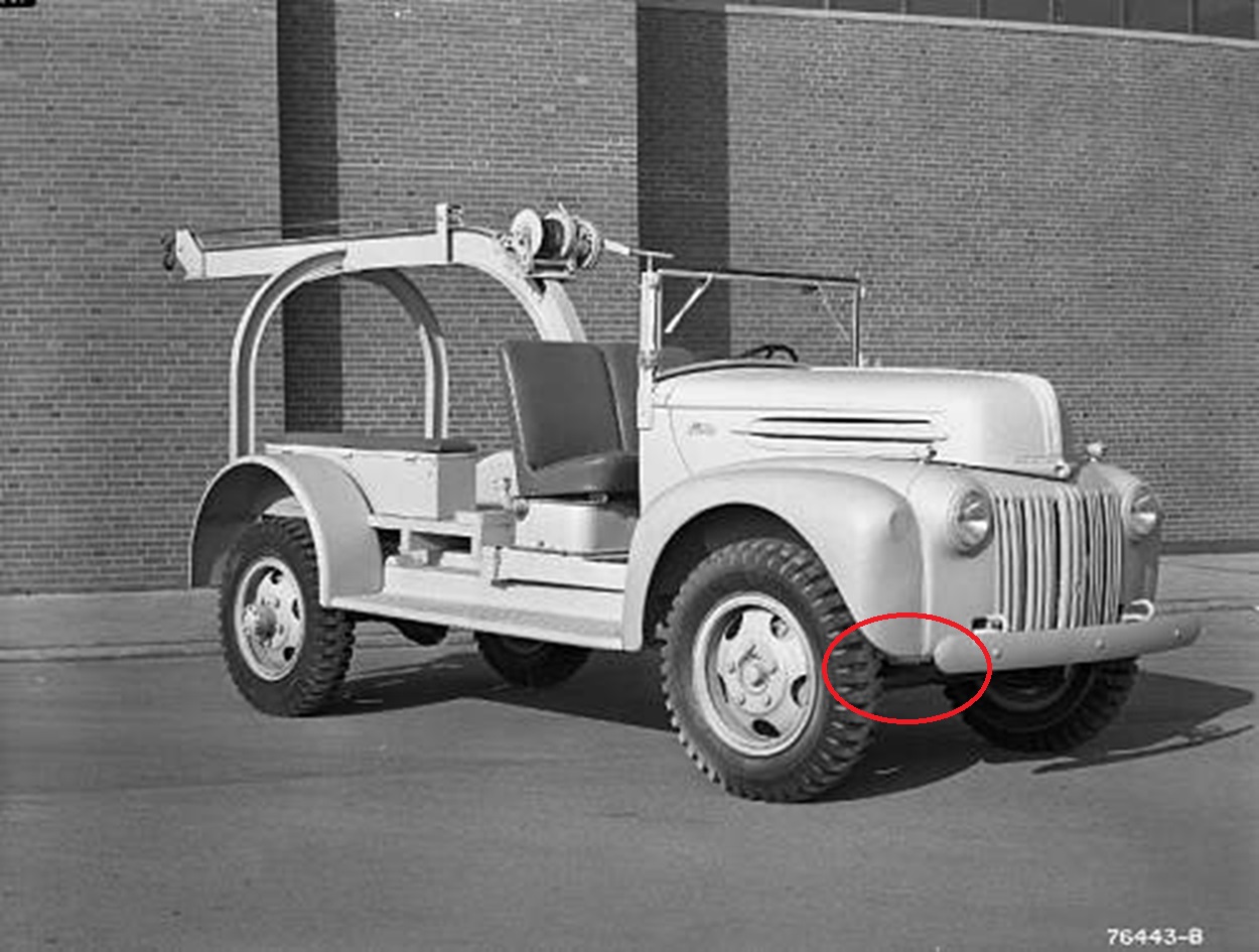
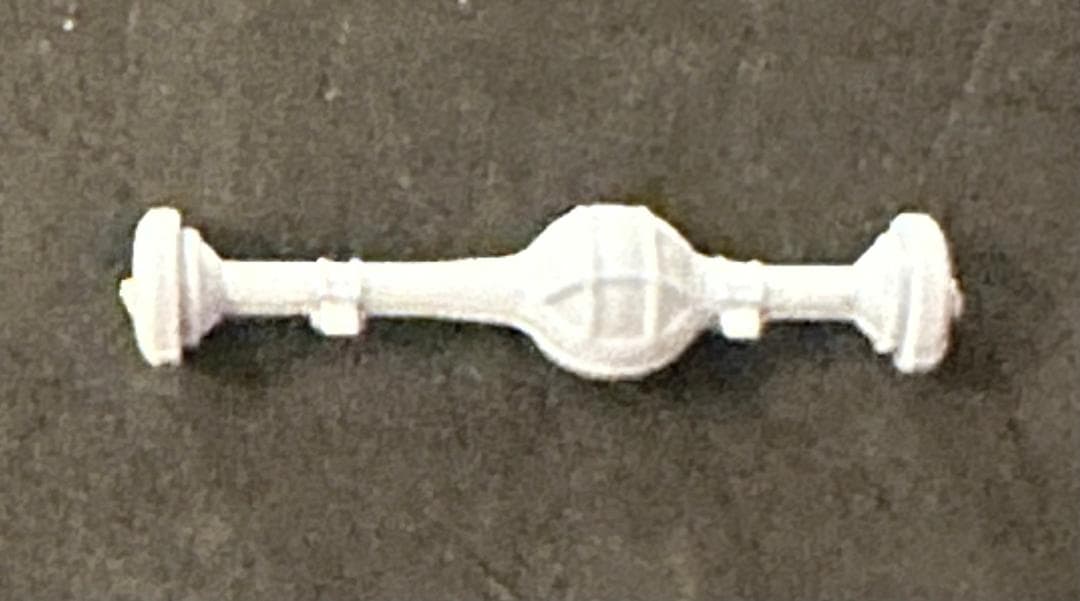
I decided to kitbash these kits by mainly using the Airfix M6 kit with a modified Ford cab. I can use the Ford front axle as well. That means that I have a left over Chevy differential (pumpkin) with the distinctive ribs on it.

You might recall my G7107 conversion above in which I commented that the rear pumpkin would be incorrect. Now I can fix that. I just have to center the pumpkin in the axle.

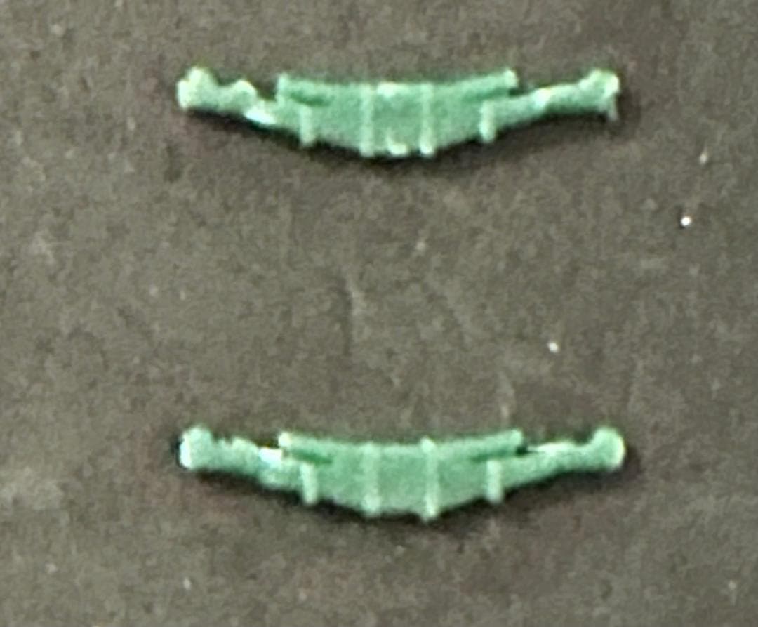
The next bit of luck was the rear springs from the Ford truck that I would not be using.
After a little alteration, these:

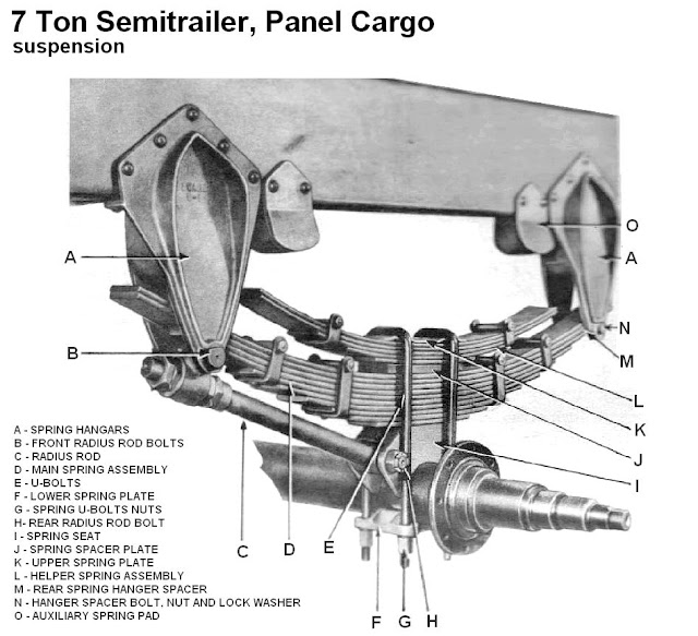
Can be used for this:

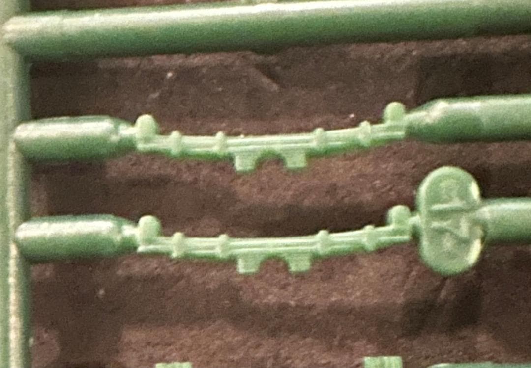
And finally, the other part of the G7107 build that bothered me was its rear springs. I had to try to cobble together springs for a single axle from springs for a double axle:

The results were not pretty:

I tried to tell myself no one would really notice, as with the differential. But I notice, and it bothered me. Now I can use more appropriate springs left over from the front of the Ford.

Now on to building. The Ford cab was a bit of a disappointment, the PST kit actually supplies a cab from another one of their kits that you have to remove the side hood panels from.

Once that’s done you’re left with an incorrect door angle. But since I’m cutting up the cab, I have to remove that seam altogether. Once again, my favorite method - CA, accelerator, sand - takes care of the problem in less than a minute.

This:

To this:

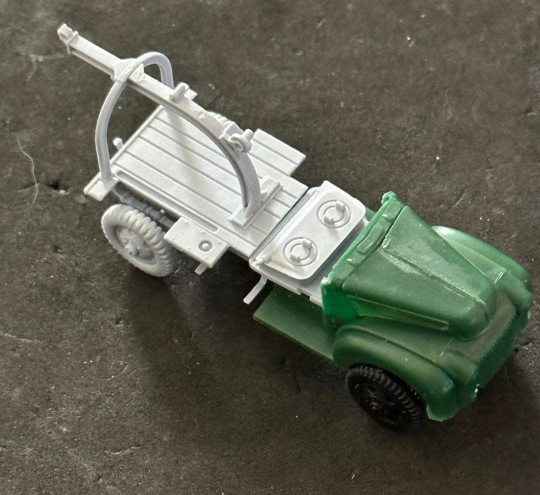
After cutting the cab I discovered none of the PST parts work well with each other. The upper cab, lower cab, and floor don’t fit together at all, So I just temporarily glued the lower cab to the Airfix frame to see how things would look, At this point I was more concerned with getting the frame level front to rear. The frame is level, but that Ford axle looks a little low, even though where it is puts the front wheels at the right height. At this point, the fenders still sit too high over the front wheels, so maybe lowering everything will make the axle’s position look better. Also, when I actually cement the front of the lower cab to the frame, it will sit level. The part has a slight warp that goes away.

The whole thing starting to come together:

I’ll need to extend the rear fenders on this ford version by splicing fenders together from two of the Airfix Chevy kits.

7 Likes

Another interesting variant, also by Ford, and not phased out until 1967.

:thinking:

5 Likes

I’ve begun work on the Mk3 Mod 1 bomb trailers. I’ll need at least three, possibly more If I decide to put an empty one on the above Ford. I’ve found a nice 3D printed version that can be done in 1/72 scale.
I’m fairly certain the quality will be good as I’ve purchased a 1/48 White 666 from him on the past.


A brief aside - I was in the LHS the other day and spotted a Williams Brothers C-46 Commando. I’ve always wanted to do one,. While doing a little research on it I came upon this photo:

It shows the very same vehicle, towing several of the very same bomb trailers, but during the Korean War. Funny how projects can overlap.
In fact, it just brought me to a startling revelation - the trailer frame is 13 feet long, and the tongue is 4 feet long, (more on that) while the Mk XVIII torpedo is 20.5 feet long. It overhangs the trailer both in the front and rear.


I’m not going to be able to chain these trailers together as planned. I’ll need at least three bomb trucks now, each towing their own trailer. So I guess I’ll order two of the 3D trucks.

Ah well… At least I do have very good references now, compliments of Jon Andrews at the Indiana Military Museum.

They also have the Burma Jeep in bomb servie configuration right next to the trailer.
Thanks to him again for more photos.

So that’s where I am, more scratch building, more vehicles, and slowly wreaking havoc on my Gato by cutting away all the unnecessary bits.

Edit: Those are NOT the same bomb trailers as those I’m building, but still - the math says my larger trailers still wil not work.

7 Likes

Woah! Stop the presses! I just found this company. I’m sure many of you already knew about it:

Dude says he can do the bomb service truck in 1/72. It’s an actual kit with an engine - not just a single 3D printed piece.

Judging by the wheels alone, this is far better than what I was about to order.

8 Likes

AFKWX, hard or soft top
mmmm :heart:

Well doggone it! Even the simplest things aren’t so simple. The C channel for the main frame rails on the bomb trailers are 5 inches high. That works out to .06944 in 1/72 scale - essentially .07 inches. Evergreen does not offer .070 channel. Only .060 and .080. I know the difference of .01 inches seems insignificant - and it is - at any other scale. But in 1/72 it’s nearly 3/4 inch on a 5 inch component. That’s a greater percentage of error than putting 1/32 items next to 1/35!

So I thought I could make it from .050 strip with flanges made from .010 x .020 strip - .050 + .010 + .010 = .070. Perfect! Except that once again, Evergreen do not produce .050 strip.

Soooo…

I’ve take .060 angle and cut down one leg of it to resemble an L. Thankfully I only need six pieces, all just over 2 inches long. Now I just top that off with a .010 x .020 flange and voila - a .070 channel.
Of course, if there are any irregularities in my cutting (there won’t be - I know myself by now) the trimmed piece of channel would be on the underside of the frame rail where it would hardly be seen, if at all.

.060 x .060 cut into L beam:

5 Likes

Did you consider using the .080 channel and sanding down the flanges .005 each?

1 Like

I actually did. Advantage - more space between the flanges for the cross members. Disadvantage - hard AF to maintain thickness along two inches. A wave across a top or bottom edge would be more noticeable than one on an inner edge.

2 Likes

That service truck is really cool! what a great find.

It’s funny, once you get into this type of scratch work, your eye (unfortunately) doesn’t lie. As only .010" sure looks obvious once you’ve decide that it doesn’t matter and build it anyway - once you’ve done that, it becomes immediately obvious that it’s wrong!

I realize you are moving ahead as planned, which I would do too - thinking about this though, I might try and cut and make little channel using .015" sheet material - cut down the main part, then add the flanges. But that might not be an easy feat - just cutting consistently even (parallel) strips would be a headache, followed by trying to glue them all together and keeping them uniform.

I suppose you could use sheet material and and .010" x .020" strip material for the flanges - if they even make that size?

I can report with clarity that I have had a hard time making my own channel, which I just finished doing a 1/24 scale, and it was a PITA keeping it square and straight :man_facepalming:

By now, my bet is you’ve already made the channels!

Cheers
Nick

3 Likes

I have, and after making a few cross members to fit inside, I may indeed end up using .080 channel as discussed above. When I initially dismissed the idea, I was thinking - it’s going to be very difficult sanding .005 from each side of a two inch strip of channel. There’s nothing to even hold on to. Then I realized I was breaking one of my own rules:
Never try to make everything the correct size all at once.
What I need to do is build the entire trailer frame, with crossmembers, first. Then I have a much larger (relatively speaking) object to play with. The crossmembers will even make convenient handles as I slide the whole assembly across my sand paper. I can constantly adjust thickess by applying pressure to the parts of the frame that are a little thicker. And yes, I have a micrometer. :grinning:
So that’s the next step.

4 Likes

:+1: :rofl: :rofl: :rofl:

By sanding the outside of the flanges you also get a thinner (more in scale)
visible edge

2 Likes

See? I’m my own worst enemy - using the trusty eyecrometer :smile: that said, I do the same as you describe, build up the whole part, then sand down the whole part/assembly as a single unit. Or, if that doesn’t work realize the eyecrometer was wrong, and…rebuild it :smile:

3 Likes

My little Ace kit arrived from Poland today,
This was my inspiration.

image

And this is the kit:

There are notable differences that I could easily change to make it “close enough,” the placement of the door hinges, the engine vents, even the grill. But I don’t like “close enough” if I can avoid it. I’m confident enough that the cars came from the same maker that I’m just going to build it stock. If one variant was available in Australia then certainly the other one would have been as well. Even the seats are the same. So, maybe dropping off a sailor after a night on the town?

Now what about that saloon in the background of the photo? :thinking:

Or this?

They both have the correct window configuartion, I guess I’ll need both.

6 Likes