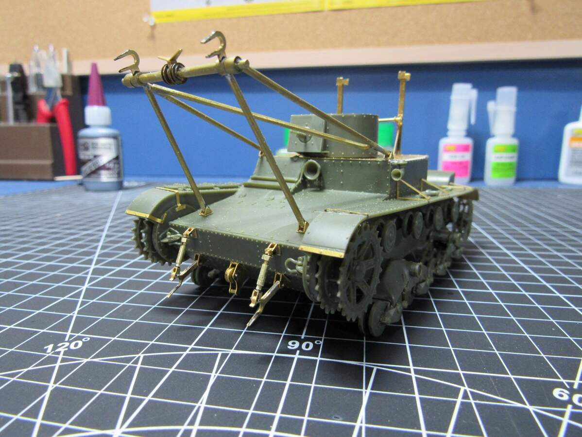
That’s all for tonight. Not sure what’s next. Would really like to get that mess of rods and tubes mounted to the front of the tank done, hopefully this weekend, I am easily distracted though.
I would still recommend to do the jig as a “1:1” printed sheet and instructions for how to tie it down.
If it is tied down and totally fixated the re-flow of the soldering does not cause a problem.
There is also the option of using solders with different melting temperature but it requires a more skilled hand-brain to do the soldering and the use of a soldering station with adjustable tip temperature. The advanced solderer could also use resistance soldering:
I think you can presume that any modeller who buys a potential kit will be sufficiently advanced and be able to use more complex methods.
A metal jig will conduct heat away from the joint, this forces you to apply more heat and/or for a longer period of time, this will then increase the risk of re-flowing already completed joints.
Heat sinks (large, cold pieces of metal) could be used to prevent the heat from spreading beyond the heat sink but this would only work if there is sufficient space between the two joints.
A larger (more Watts) soldering iron will ramp up the heat faster and might reduce the issues of re-flowing but this does not help when the joints are close together.
Another option is to solder both sides in one operation, this requires pre-tinning and then fixing the parts in postition (tying down with copper wire through drilled holes or pins inserted in holes).
Heat is applied when everything is fixed in position. Can also cause some clean-up work afterwards.
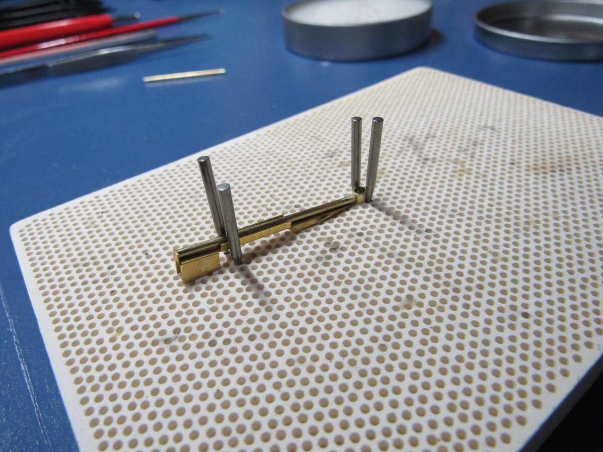
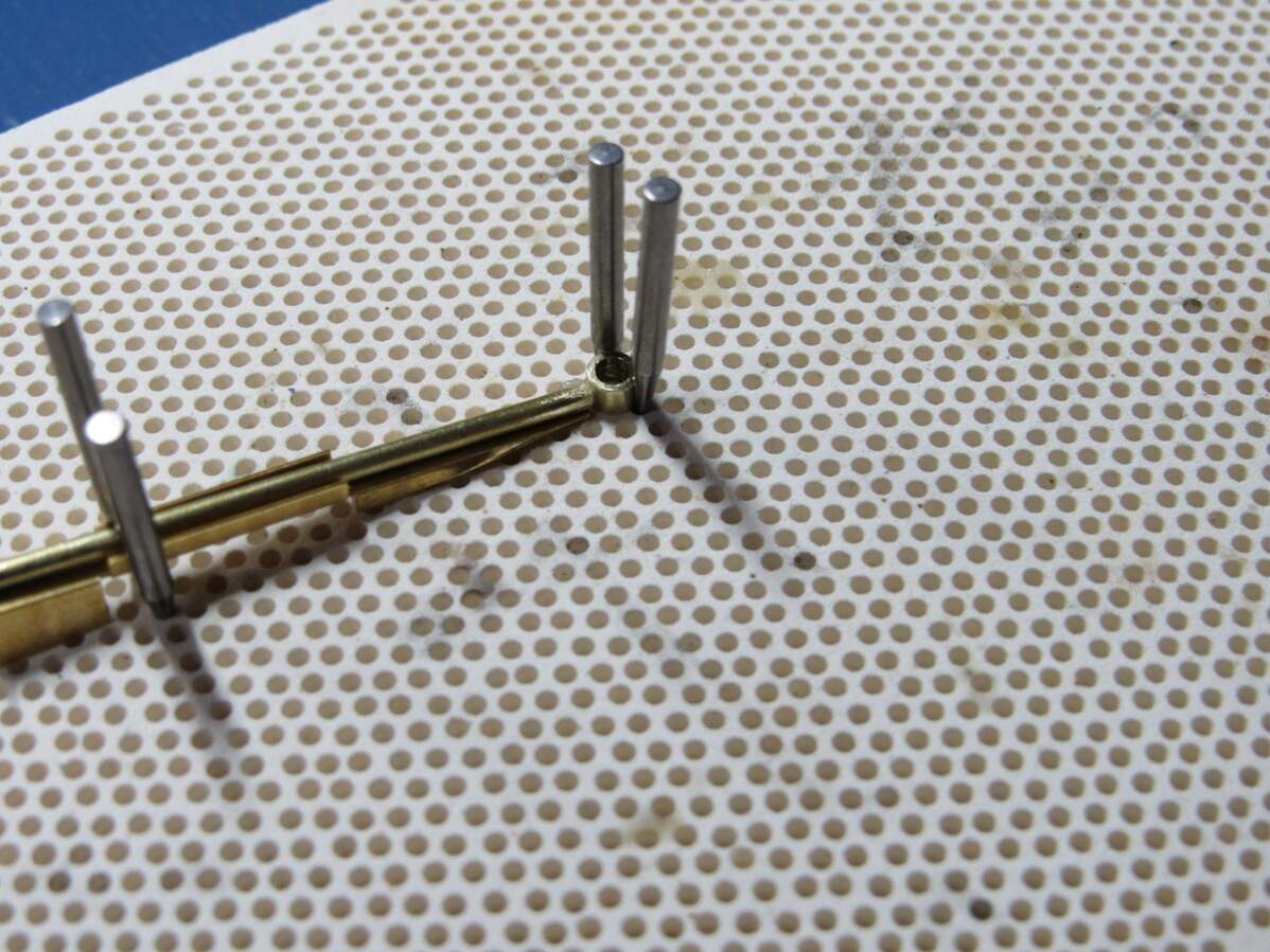
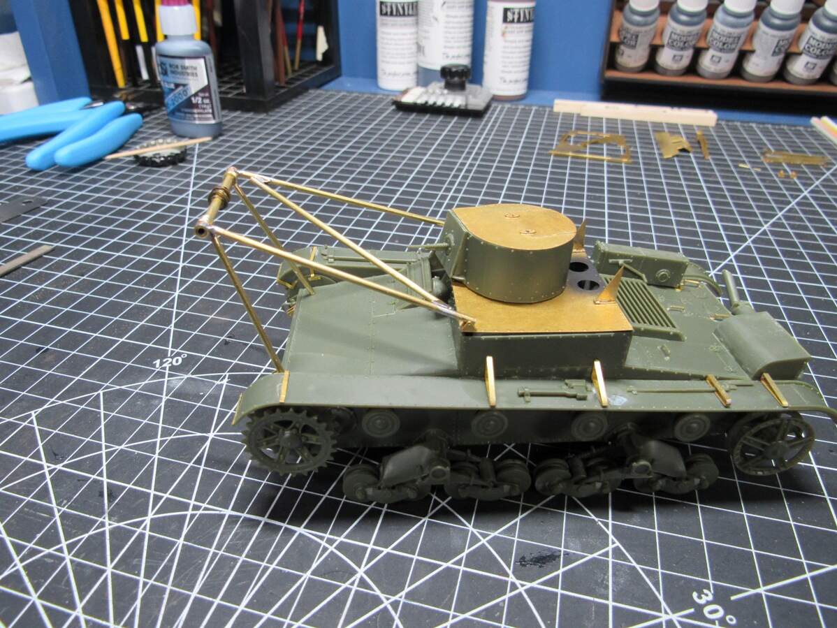
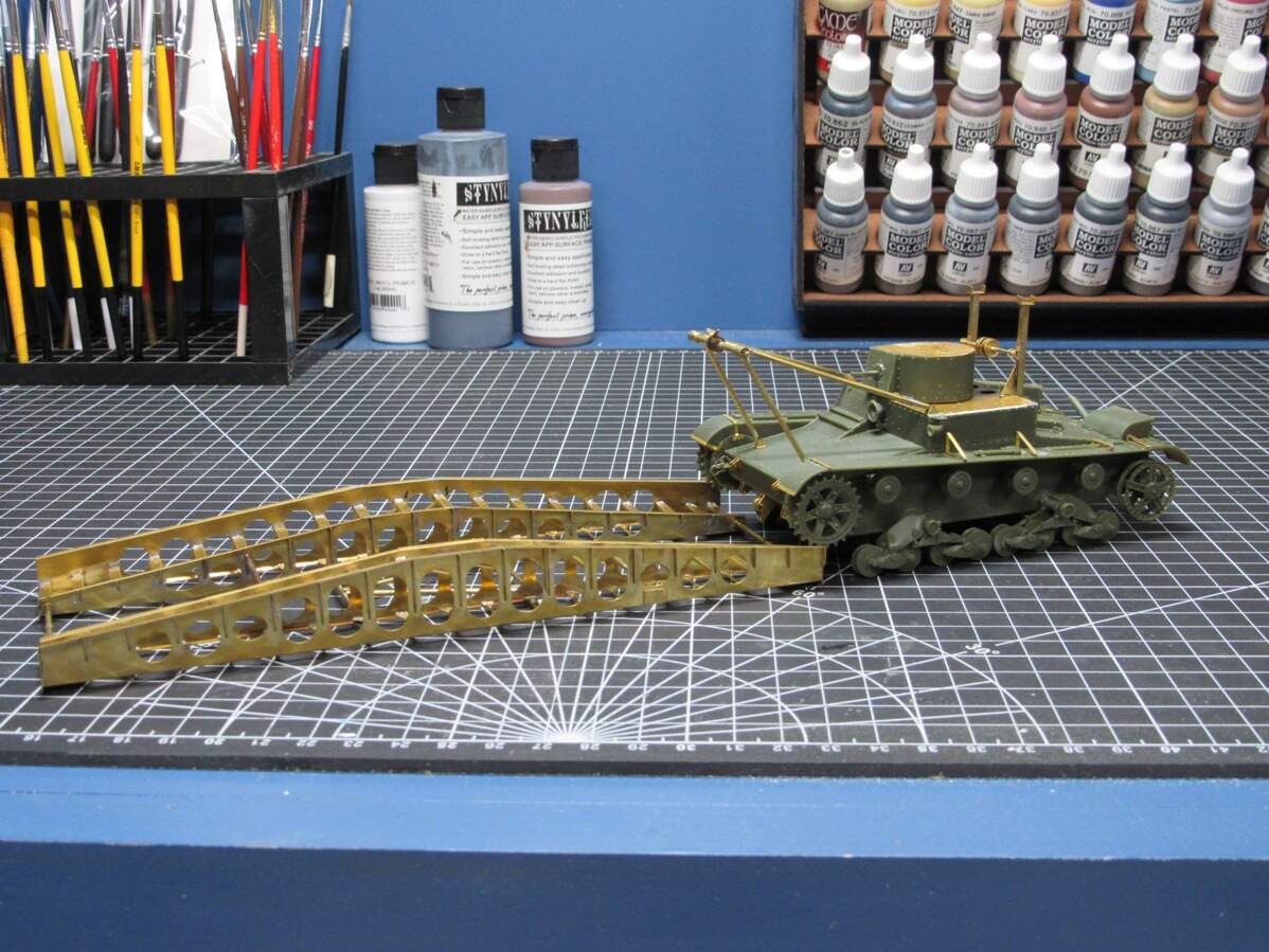
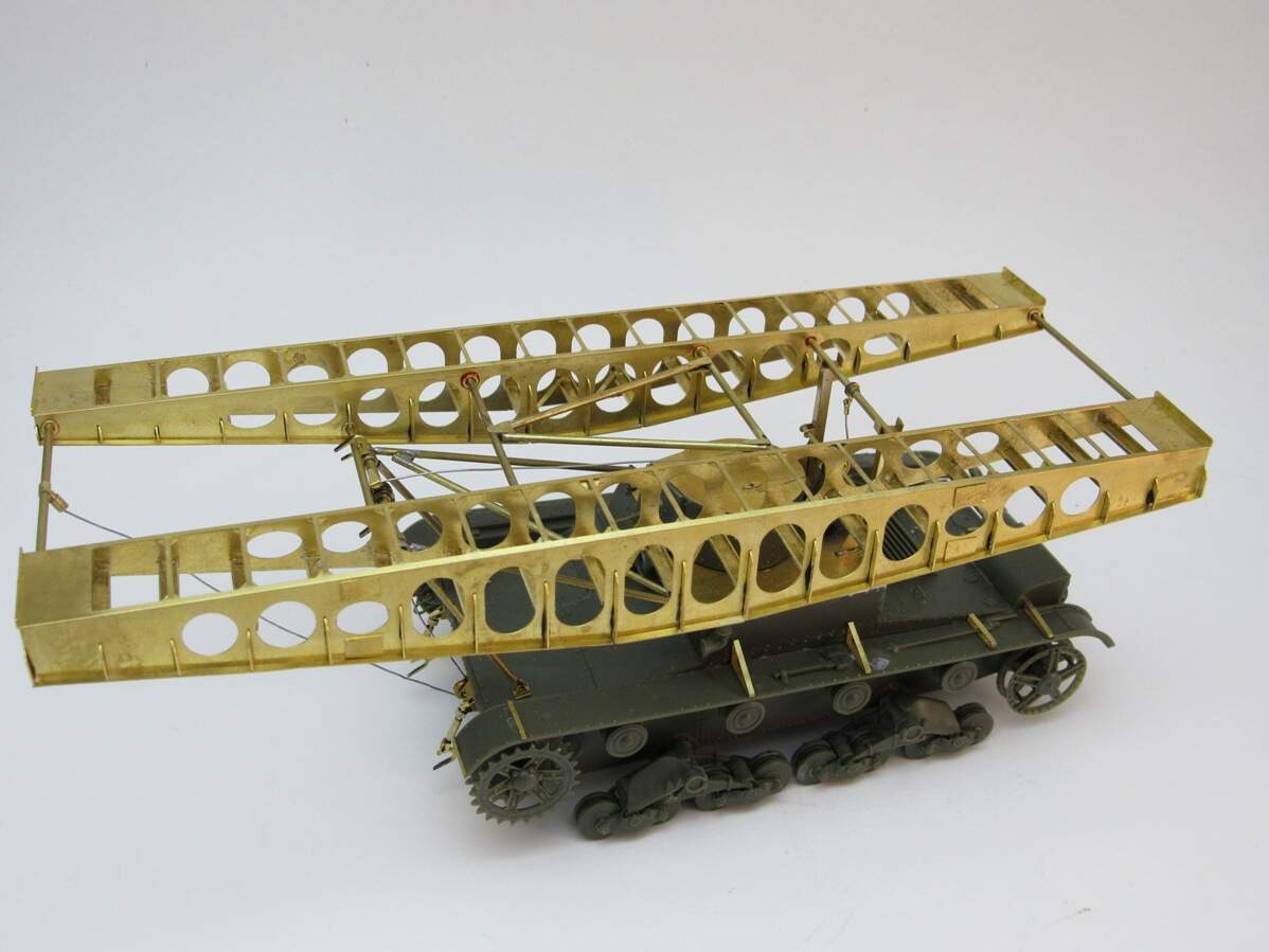
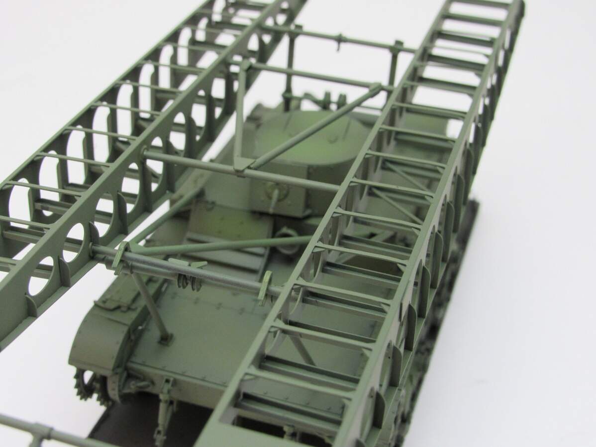
Used another PE jig tonight with success as you’ll see below. The problem with the last jig was also that I had no bend to hold the piece in from the top, so it was free to slide there. This one I secured well on the honeycomb board and it went together without issue.
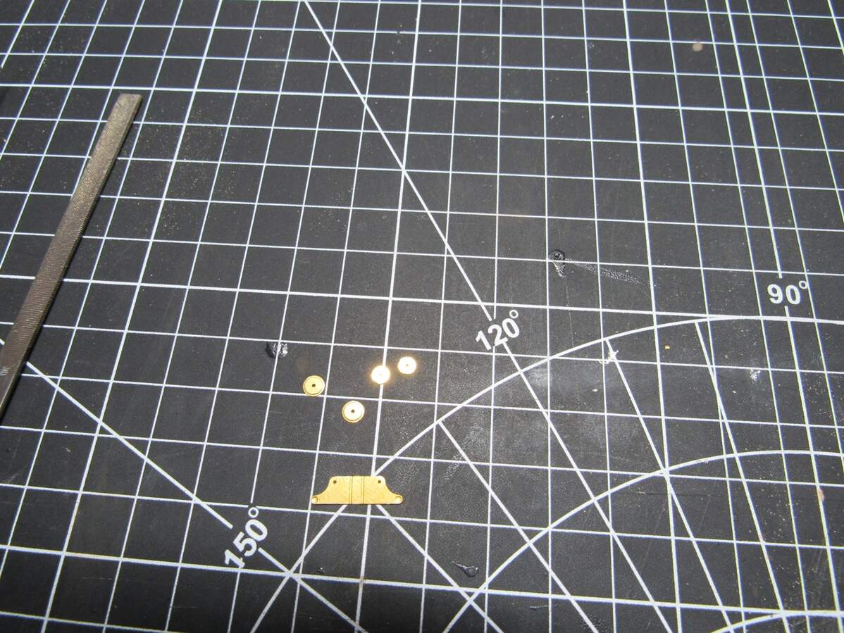
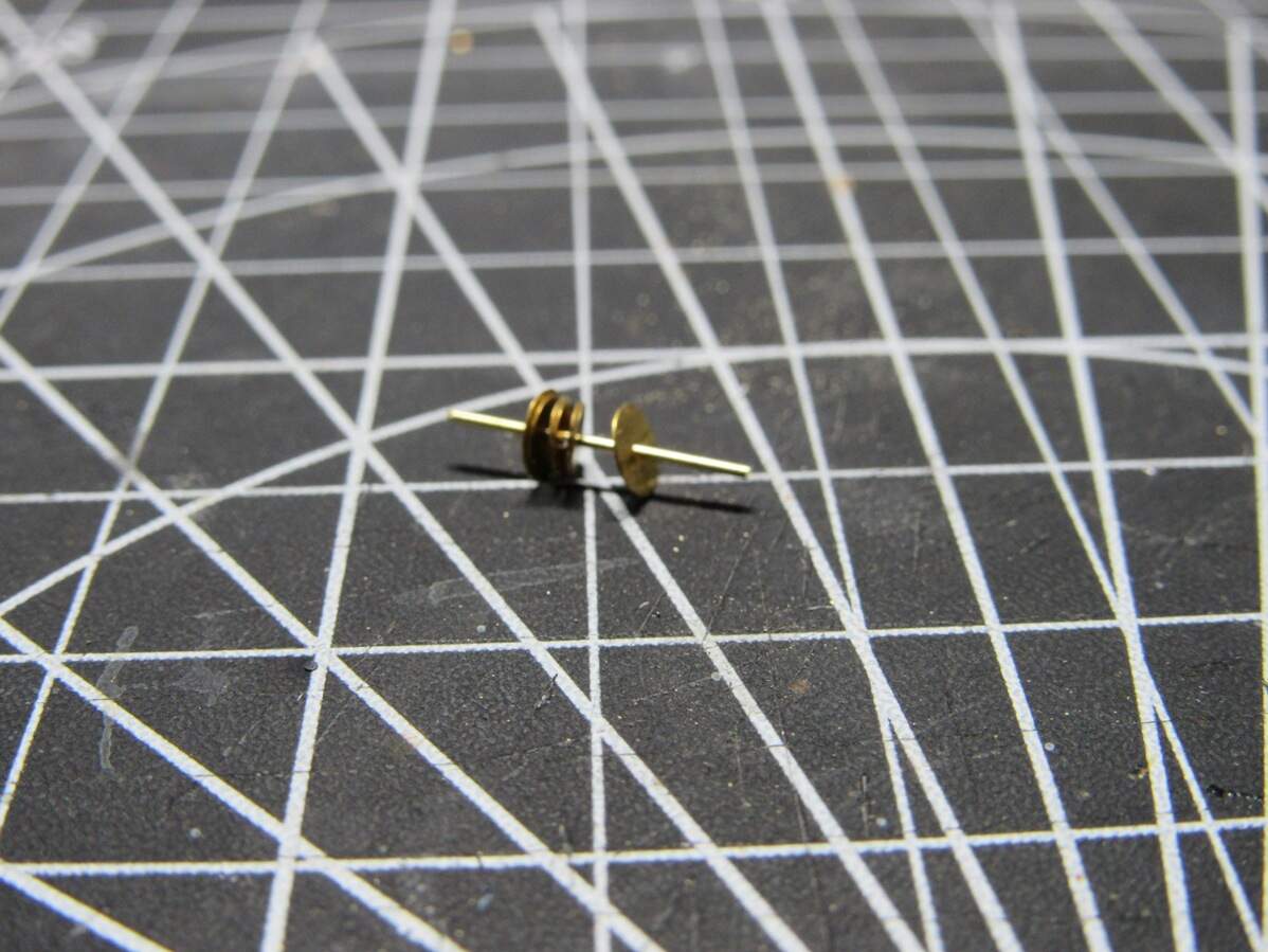
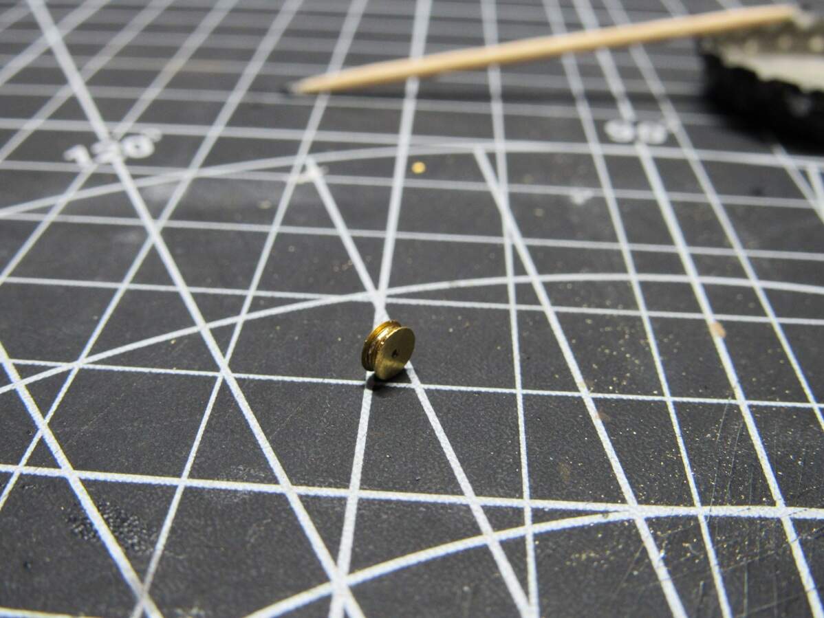
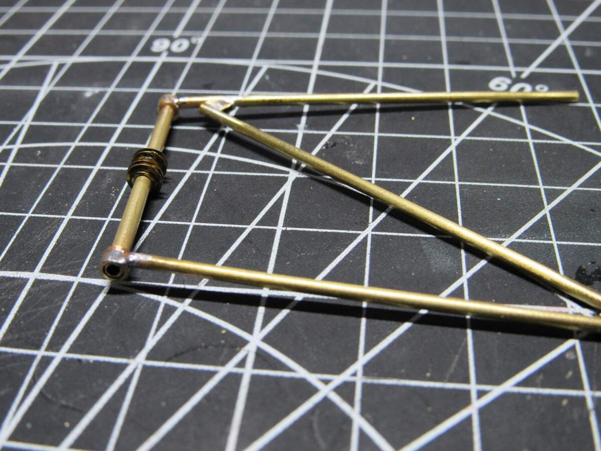
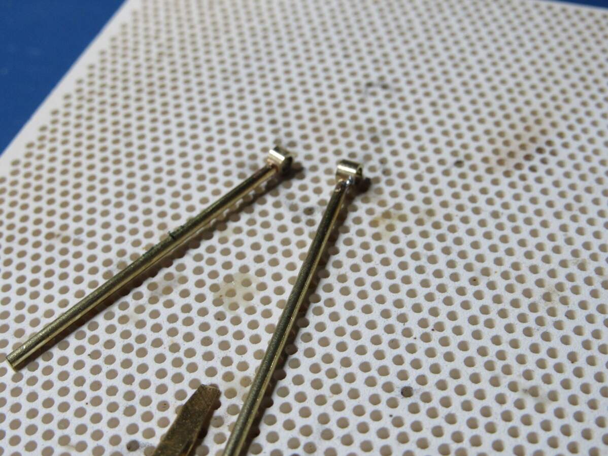
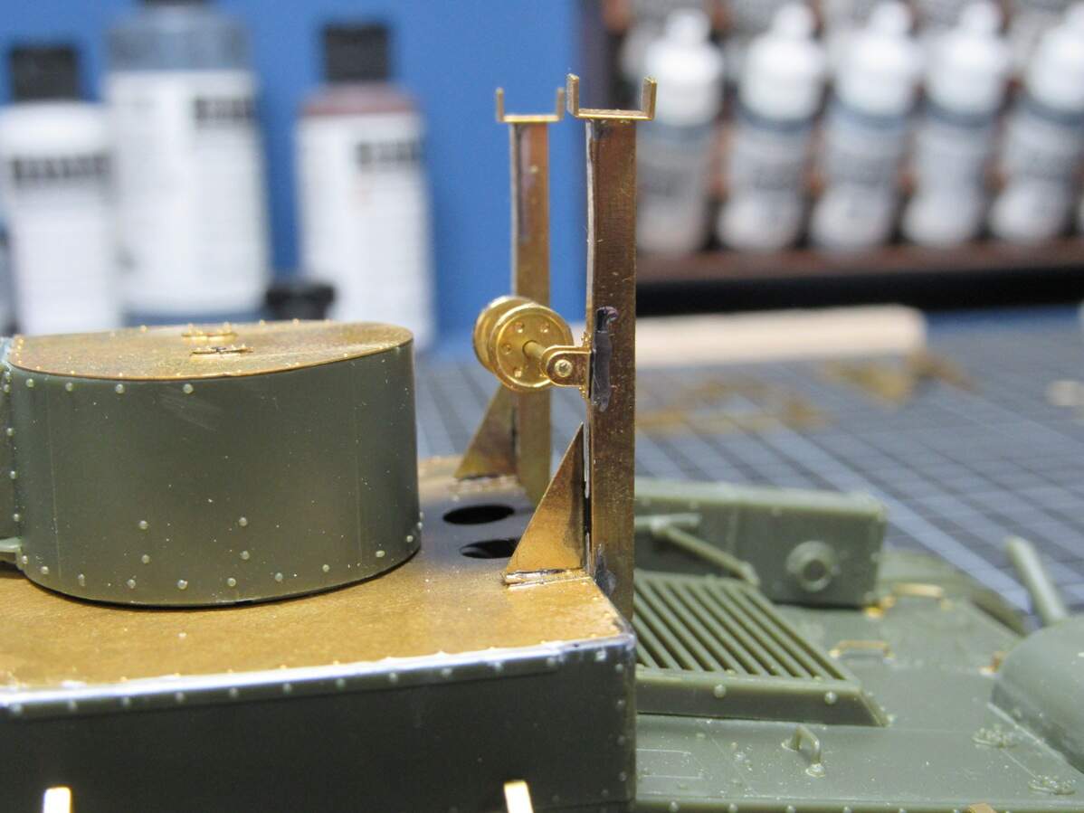
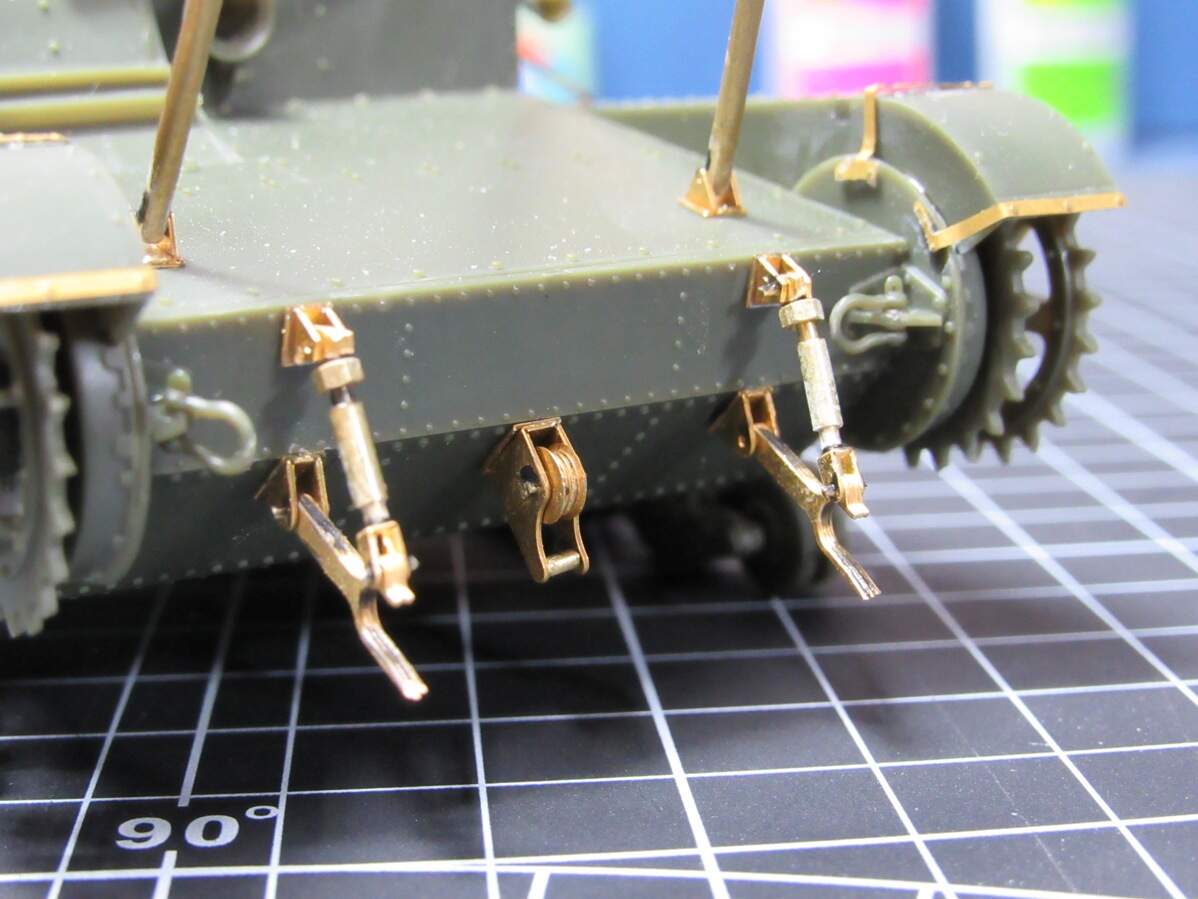
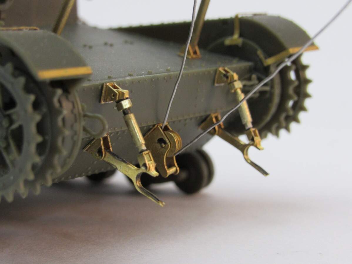
Decided to carry on with the front bridge supports. I started with the pulleys, and like the last one, these are sandwiched together from multiple PE parts.
I glued these together, soldering would just be overkill. But I did solder some short lengths of tube to the ends of my supports so that the smaller pulley rod can pass through,
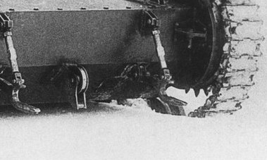
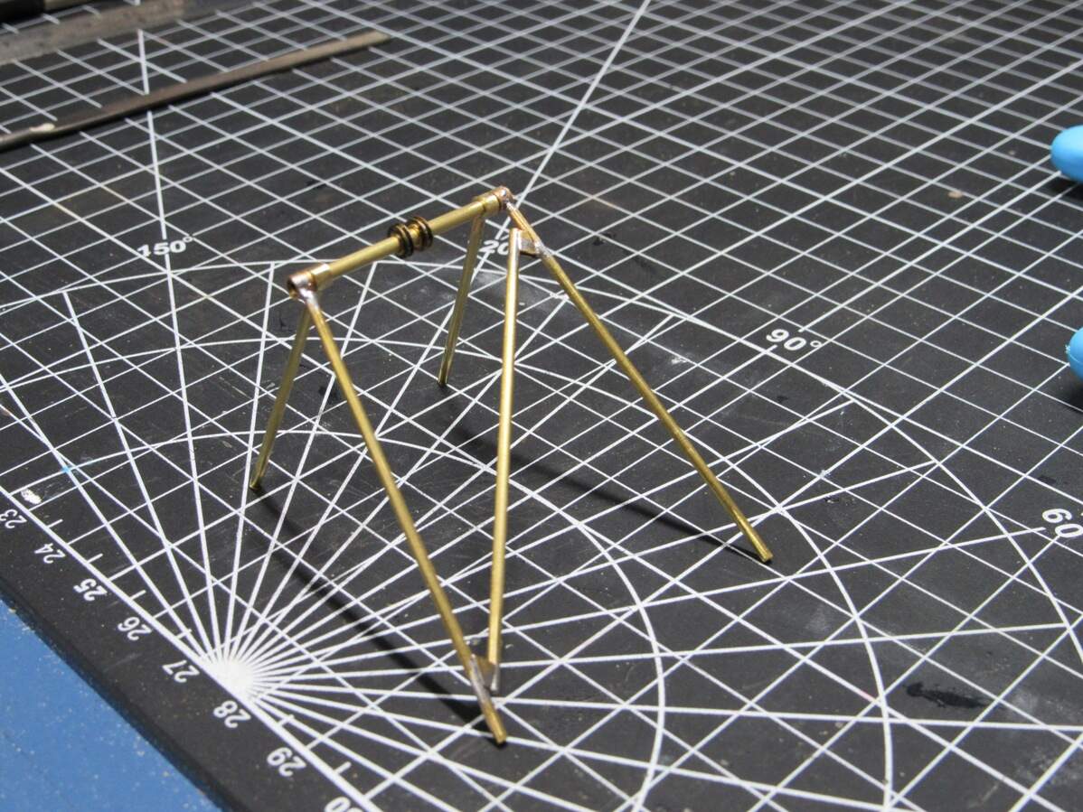
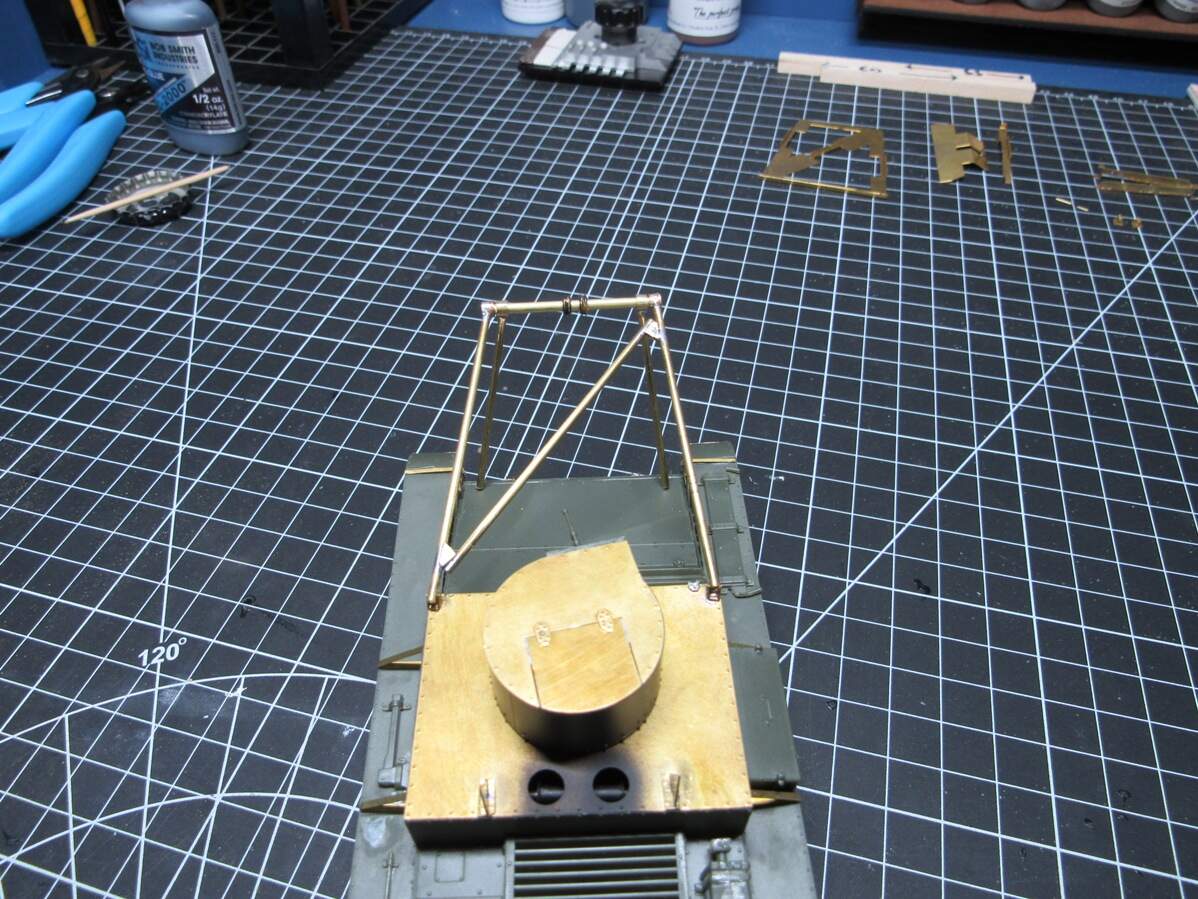
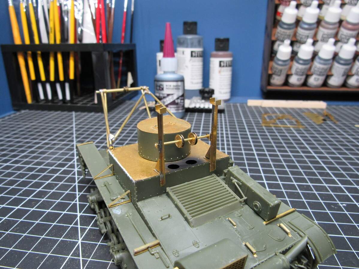
Next it was on to the supports that mount to the front of the tank, on the hood by the drive sprockets. These required a tricky angle, since the legs flare out a bit. Again, during the design phase I realized I’d mess this up left to my own devices, so I designed a jig for it,
That’s all for tonight. Think my next step will be to get this all glued in place. Still a couple details to add to this assembly too… I’m gonna need rigging
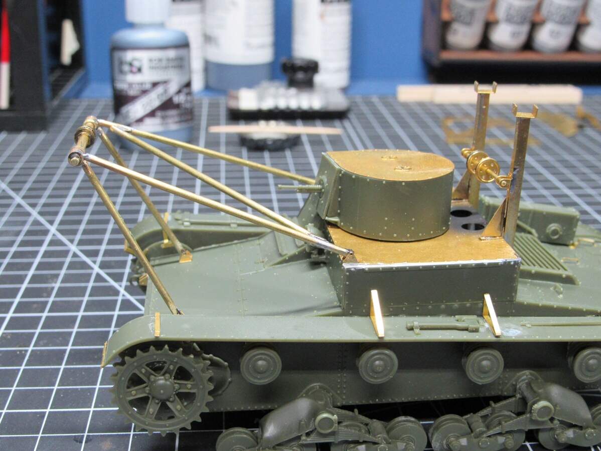
Thanks Chris, still chugging along. Tonight I focused on getting the majority of the chassis work done. Front supports were glued in place, as were the rear bridge supports.
It does! Don’t remember if I mentioned this earlier, but I was missing a cross bar on the bridge unit that’s meant to fit into those support brackets on the back of the tank, so the bridge is sitting a little more forward, and possible lower, than it actually will. Got a couple more PE detail parts and 1 plastic kit part to add, so I’ll wrap that up tomorrow. Then there’s some scratching to do, plus making another bridge, this time wide enough for the tank to fit.
Without the periods I thought you were talking about something else at first lol. I added the remaining details yesterday, both kit plastic and PE, might post a pic or two later. Then I made a start on scratchbuilding the last few parts… and after a few hours I realized, I could probably do this better with PE. So this project may go back on hold while I design and wait for the new fret. I do have another bridge to build, the proper width this time, so that could hold me over for a bit.
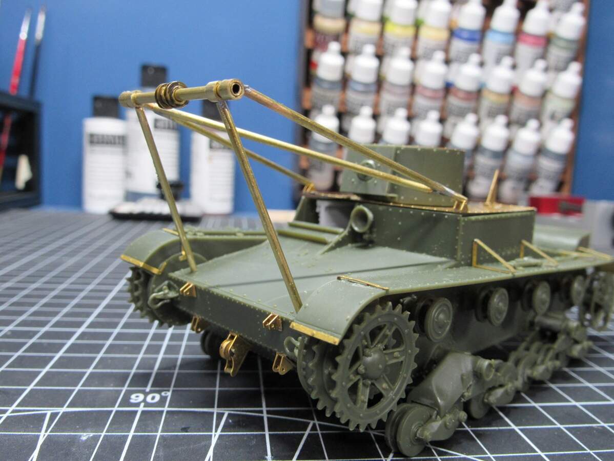
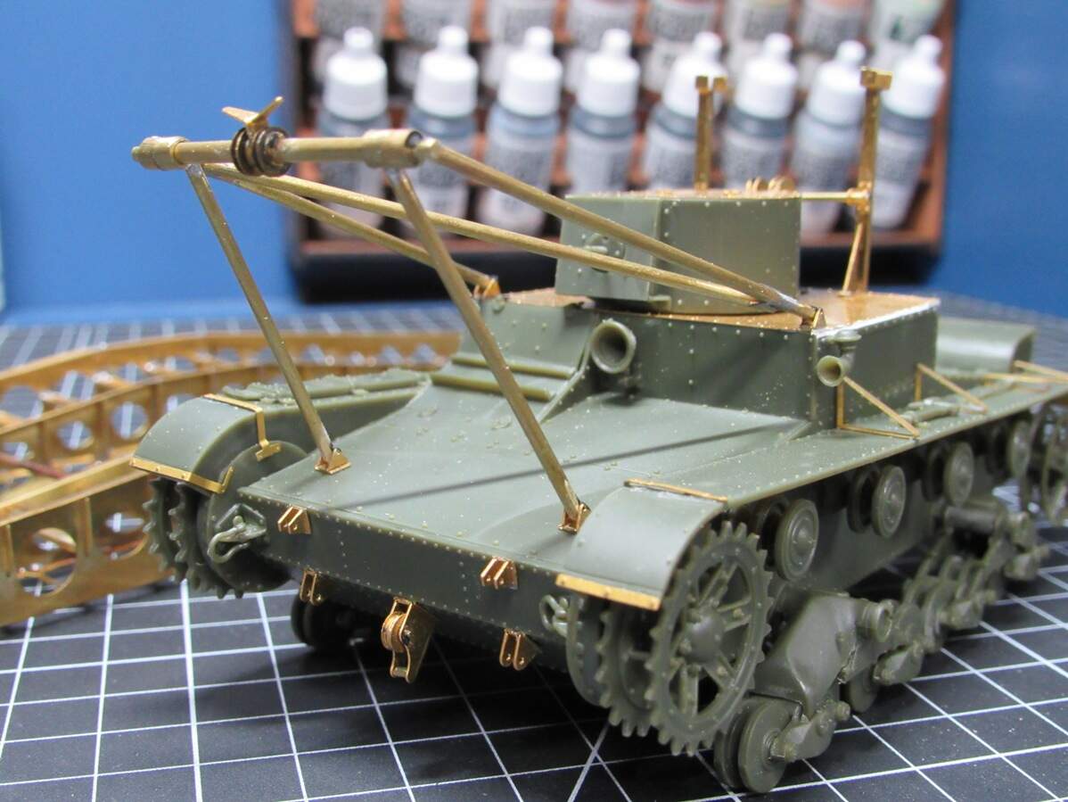
A few pics from yesterdays work, I’ll be stuck at this point for a bit, so not many updates for a while.
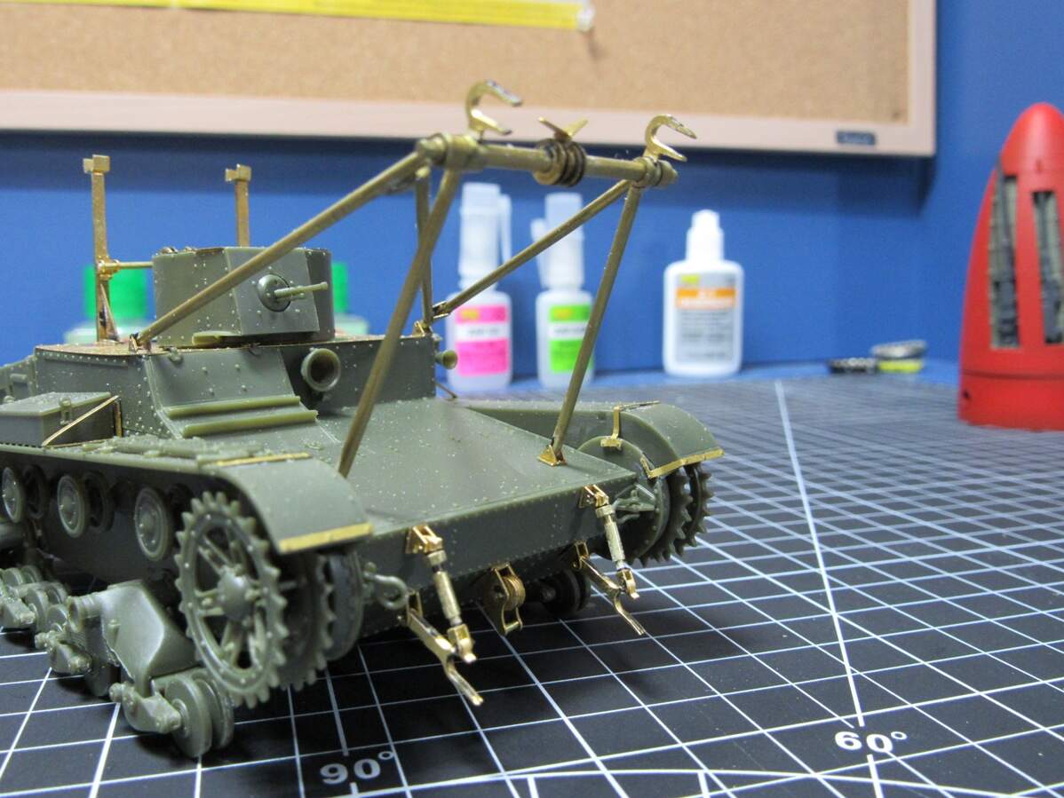
Remaining plastic kit parts added (except for headlight glass), pulleys glued in place, and what I’m calling ‘rabbit ears’ added to the front pulleys. I suppose they’re there to prevent wires getting crossed.
I think I’ve settled the cabling problem too. I have some ~0.4mm solder that seems to scale well, so I’ll just use that for the cabling. That’s all for now, back to design work
After that brief try and scratch building those parts, I went ahead and drew them up along with some corrective parts for a new PE fret. Currently in review with the manufacturer, so it’ll be another month or so until I get them
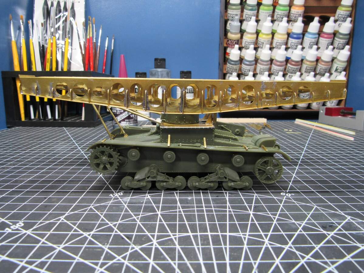
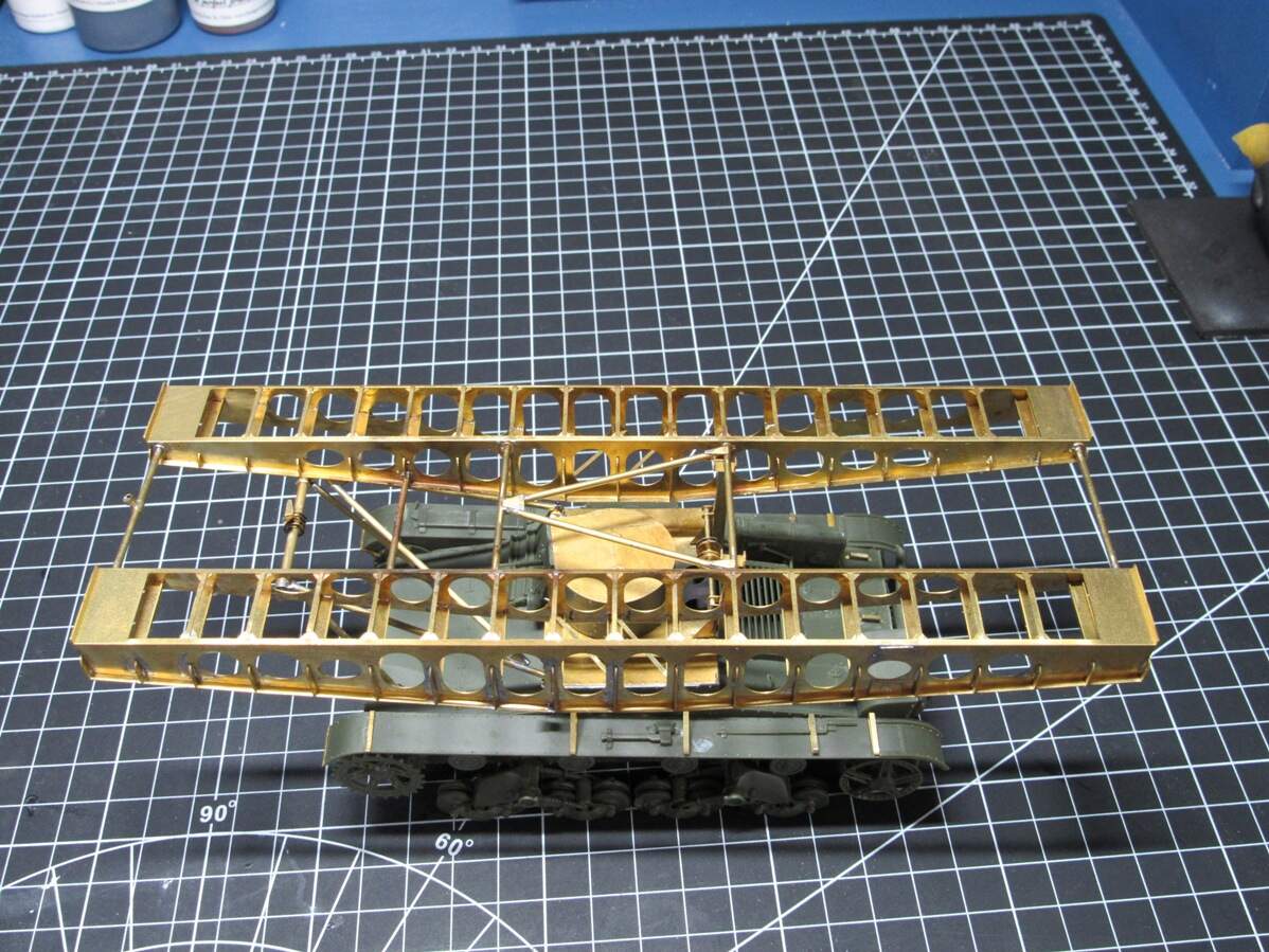
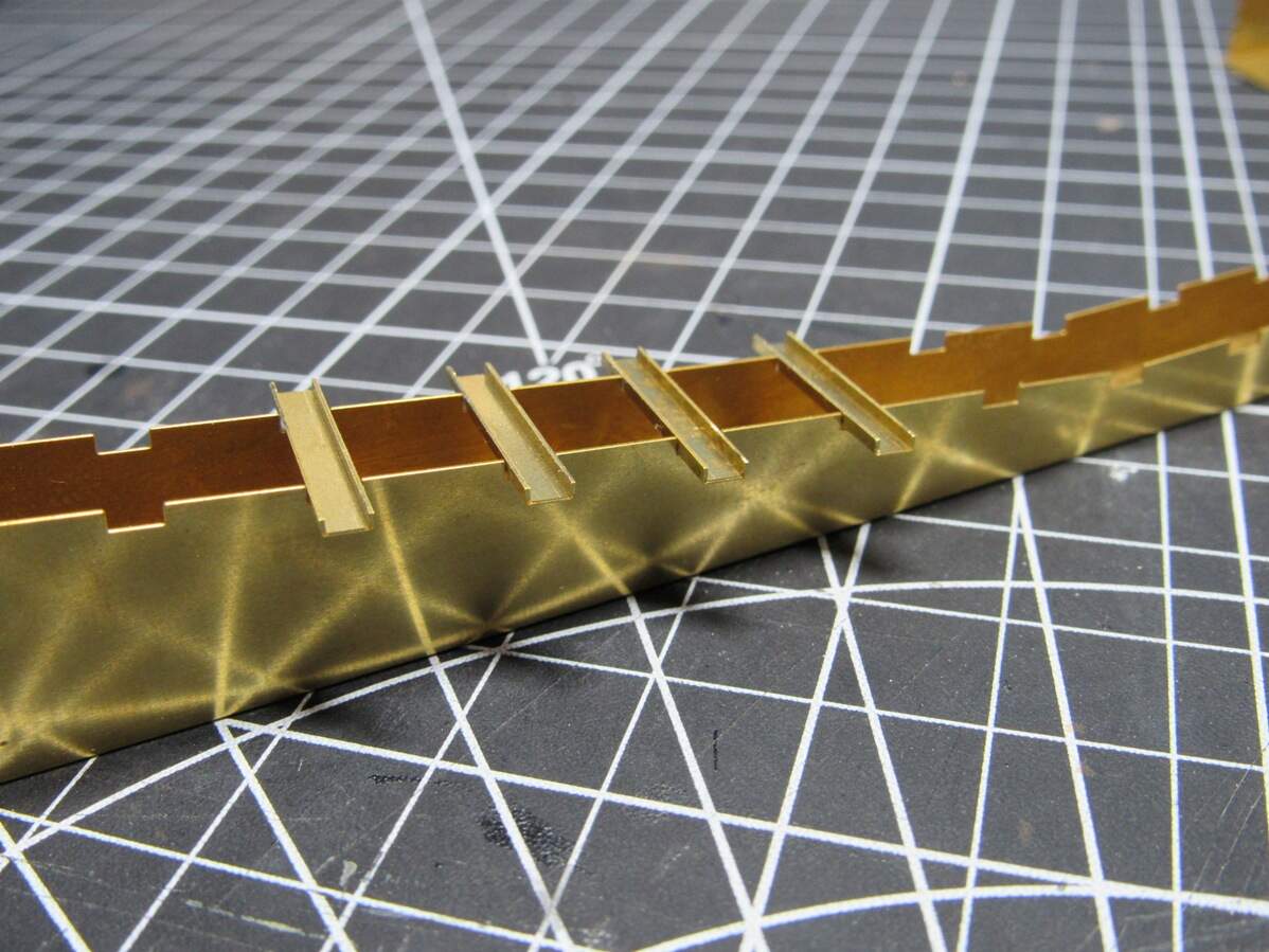
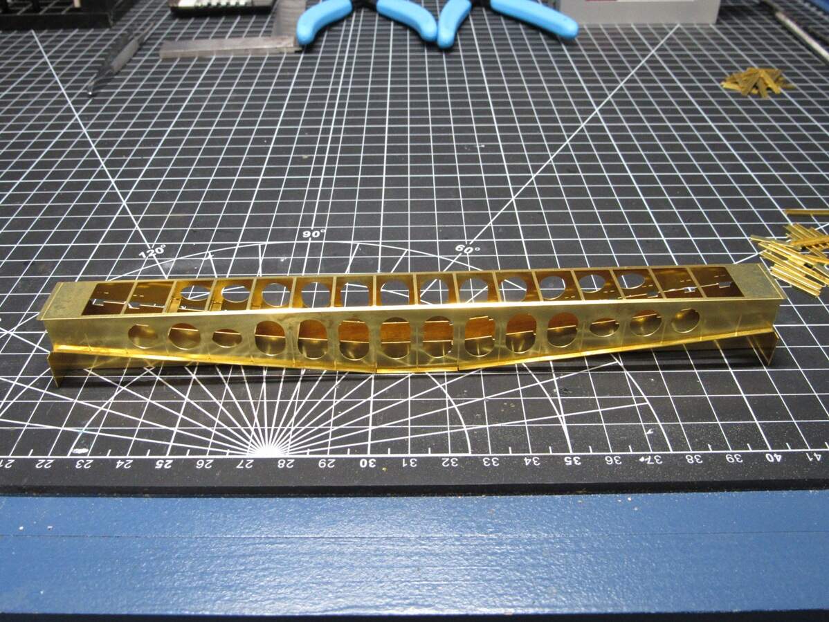
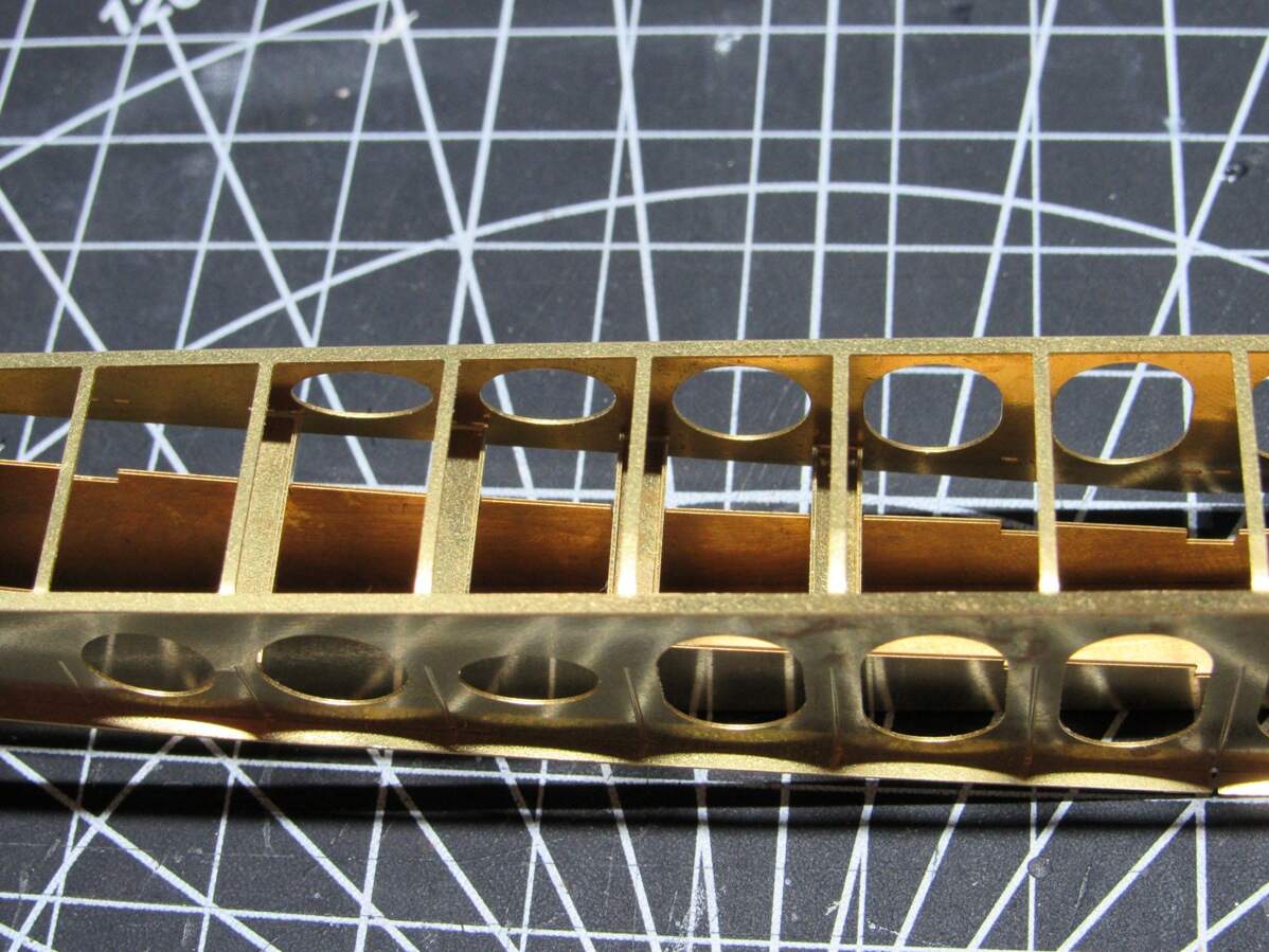
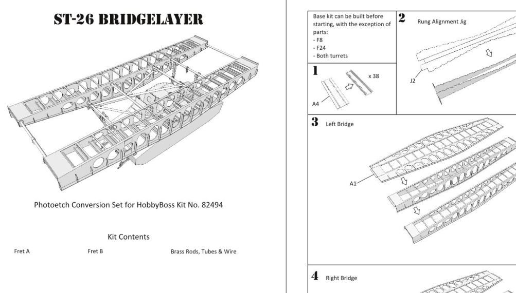
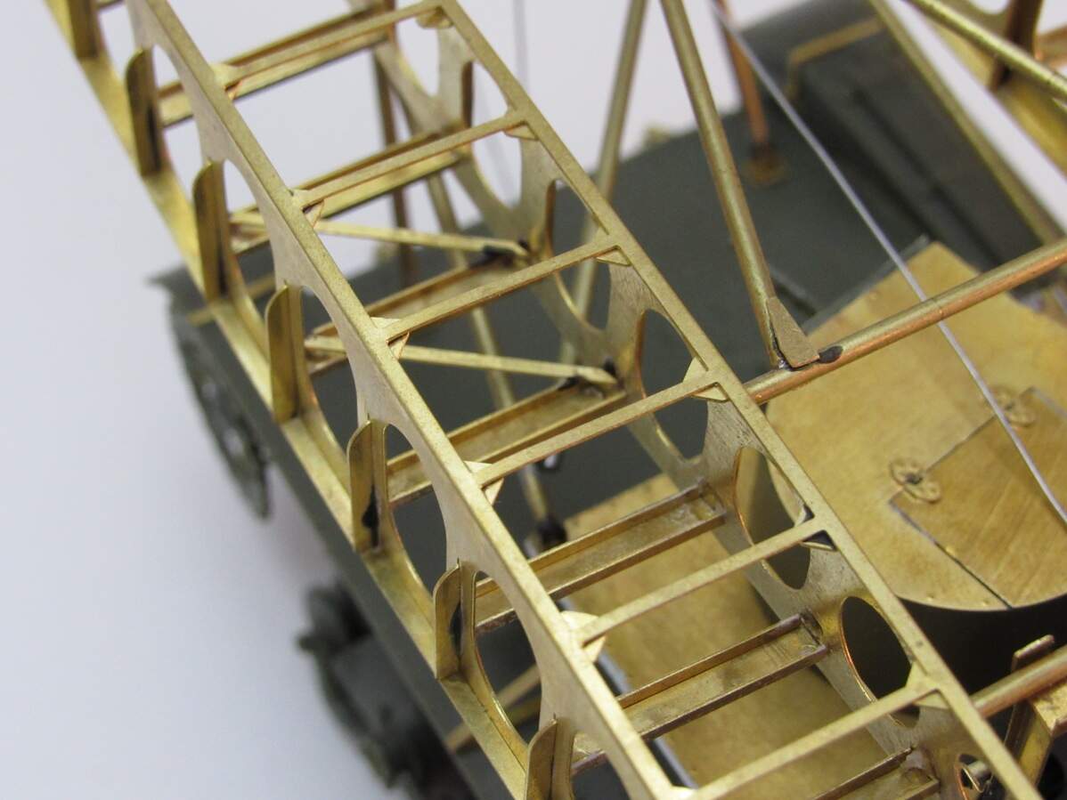
So while I wait for that I made a start on another bridging unit. You might have noticed a large weirdly crenelated piece of PE on the chassis fret. It’s a jig for aligning the ‘rungs’ of the bridge. Folded up it looks like this,
Made sure the spacing between the rungs is the same on either end so that this jig can be spun around and used with either bridging section. Not 100% sure if I’m going to solder this one or just super glue it, leaning towards super gluing though just to see if it’s stable enough. Certainly would come out cleaner looking too.
This has been a fun build and learning experience. I’m going to run with the idea of marketing this. No promise on time frames, there’s a lot of design work to do (update PE sheets with modified parts, reorganize sheets, make instructions, etc…). Hope to get everything ready in a few months though. That’s all for tonight.
Wow James, this project continues to amaze. Just outstanding. I’ve been hard at work on a client project, pretty much to the exclusion of any extra-curricular hobby fun (or any other fun). So I haven’t made any progress at all on my version. And with all of the other additional details such as what’s needed for the vehicle itself I’m not so sure it’s even worth it lol. Put me down for one of your photo-etch sets once you’re done with your design. I’ll still crack on with what I’m doing though.
Re: AutoCAD, I assume you’re using it for 3D. Regardless (and even though I only used ACAD LT 2D) the bloom has faded from the AutoCAD rose for me a long time ago. I nipped it in the bud when they decided to go to a yearly charge to maintain it. As a one-man, sole-proprietor shop, I couldn’t justify what they wanted (nearly $900/year IIRC) so I switched to BricsCAD and haven’t looked back. Lots of improvements, although the hatch library is still somewhat limited.
Thanks Jimbo. It’s been a slow process but I’m getting there.
I’m actually using SketchUp for the 3D side of things (one of the old, free versions). It’s quick and easy to use, though has its limitations. Using two separate design programs for one project has it’s downsides, mainly making sure the parts in one program match up with the other. SketchUp will come in handy when it comes time to making the instructions though.
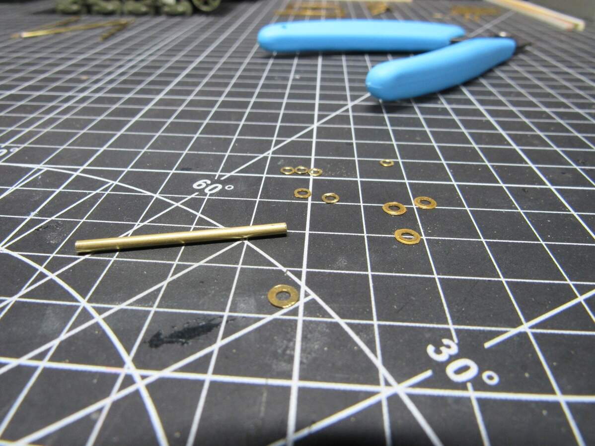
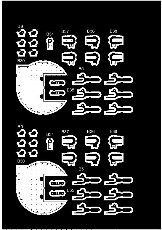
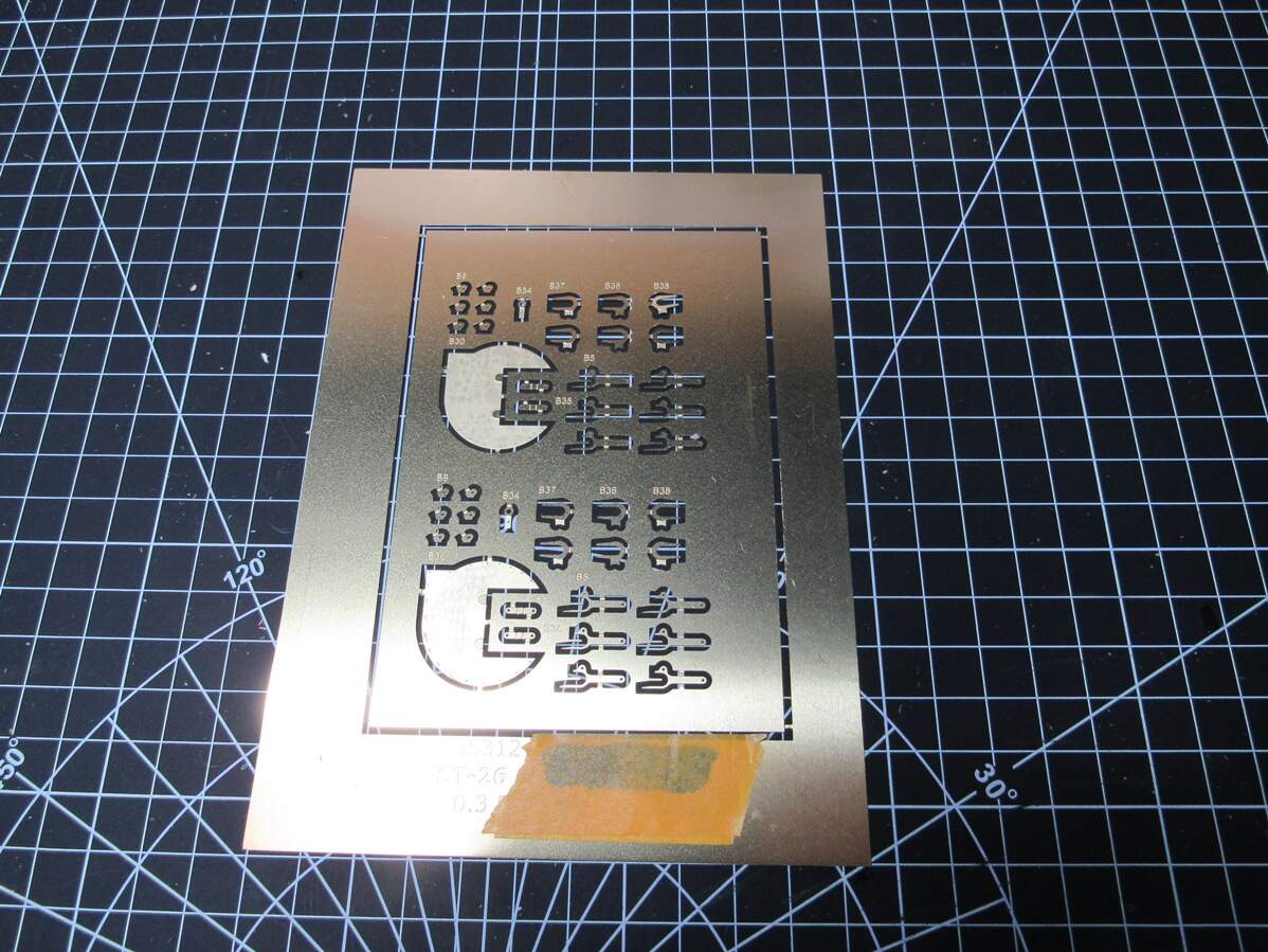
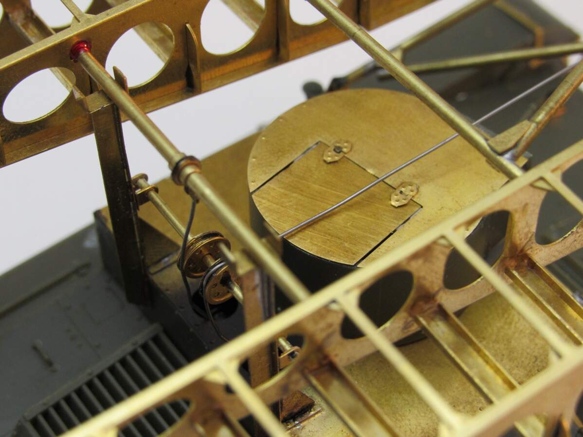
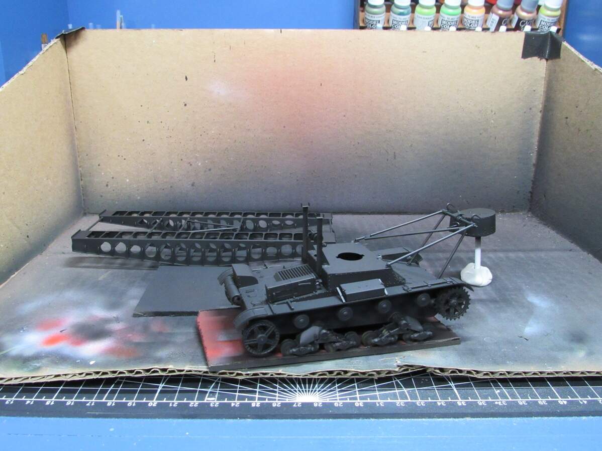
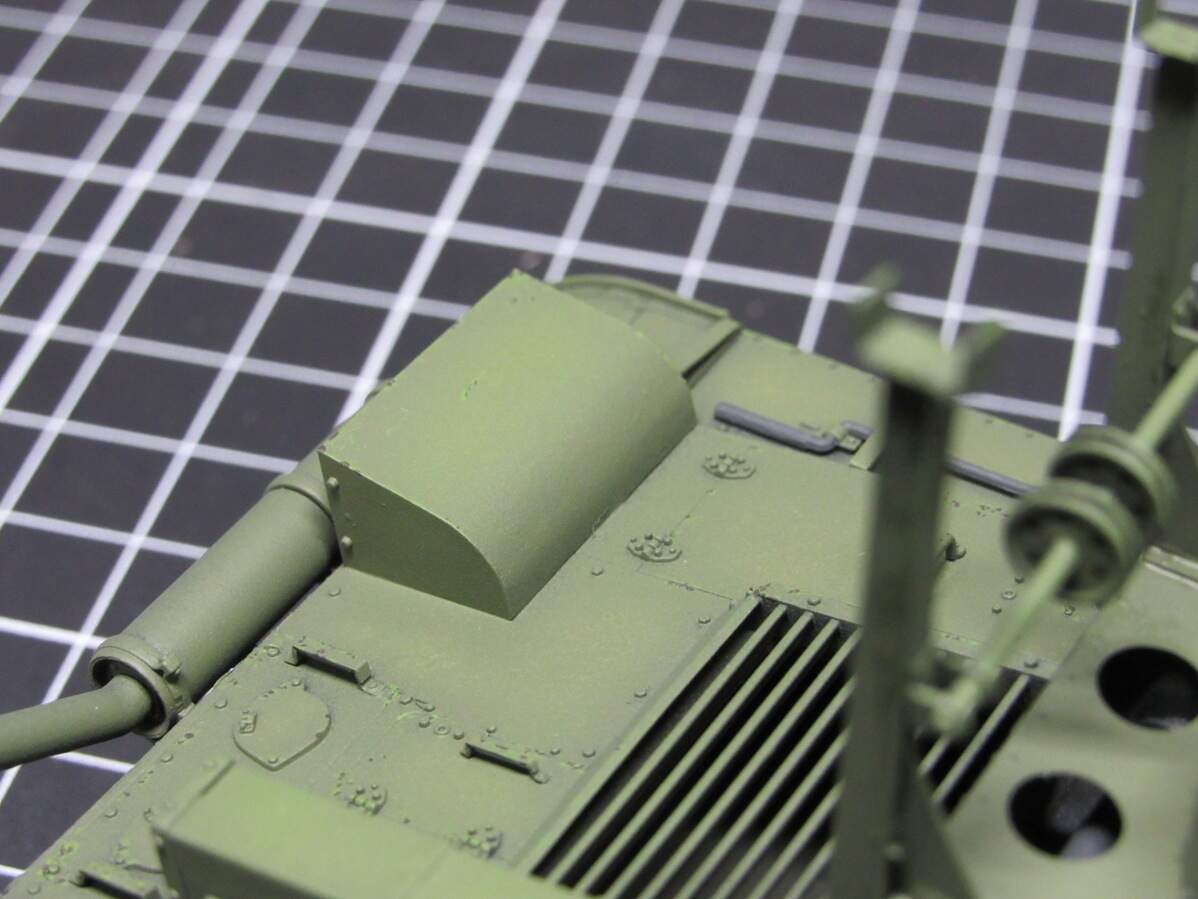
I’m back! Another fret of PE came in the mail today, what I call the ‘corrective parts’. Most of these are pieces I planned on scratch building out of styrene, but once the actual tiny size of the pieces dawned on me, I figured I’d try it with PE (the turret top parts were to see if the redesign fit correctly),
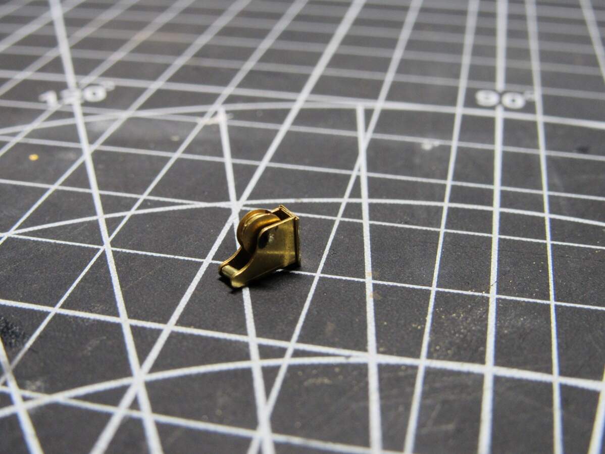
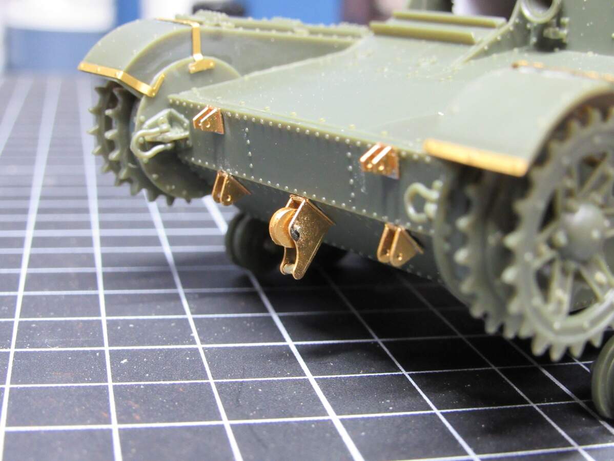
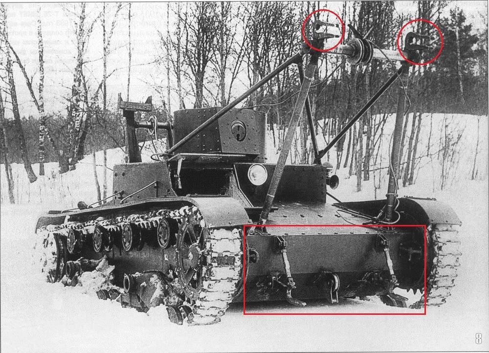
The basic idea was to build up thickness by sandwiching pieces together which worked fine. The upper portion of what I’m calling the bridge catcher was filled in with some rod/tube stock and a 00-90 small pattern nut. The parts were pinned to their mounts with some 0.5mm brass wire. I got carried away and forgot to take progress pics, but after a couple hours I got it done,
I’ll be honest, it was a bit fiddly, but with some care not too hard. It helps to drill out the pin holes beforehand. Overall pleased with the result, I think it’s safe to say this turned out better than any scratch building with plastic would have.
On the kit planning front, this last fret helps clear out the rest of the prototyping. I’m now free to run on the production AutoCAD files and kit instructions. I did get a head start on the instructions and got the bridging section done, so things are moving along.
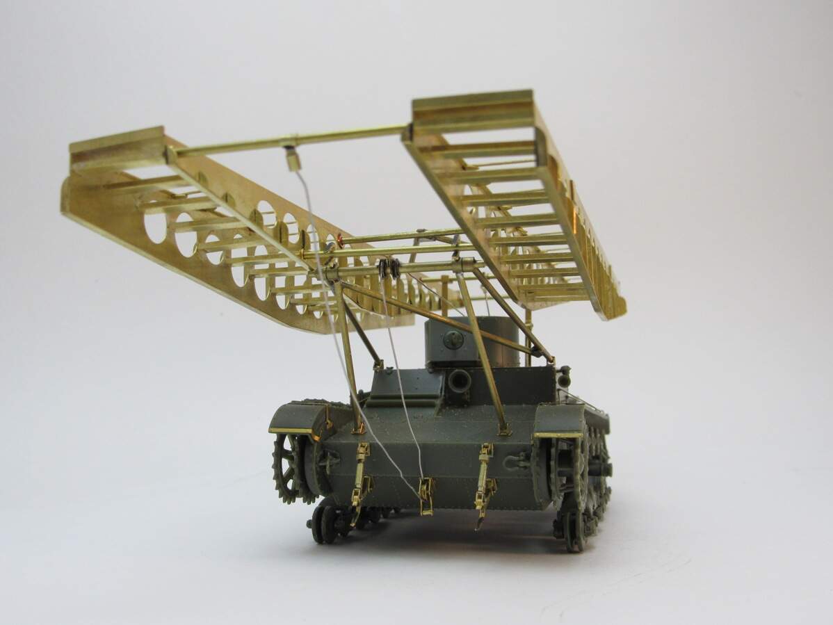
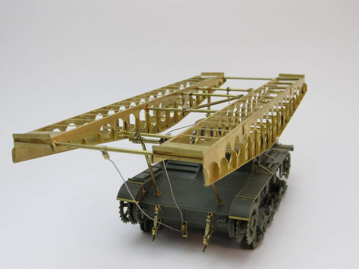
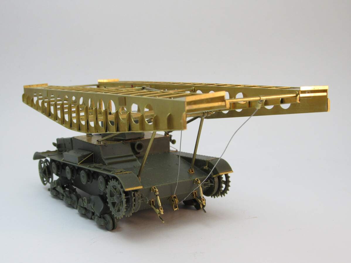
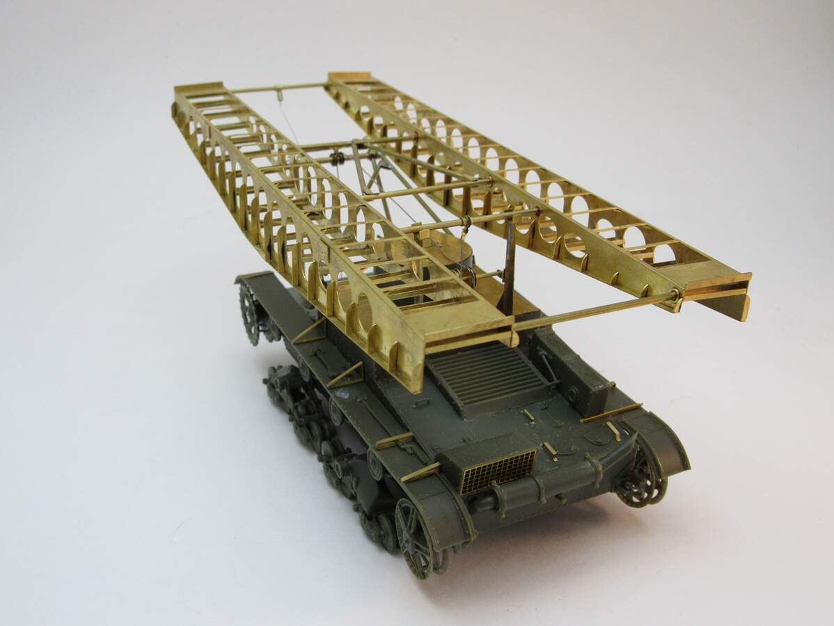
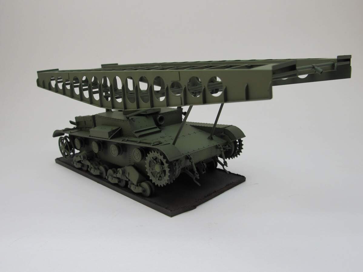
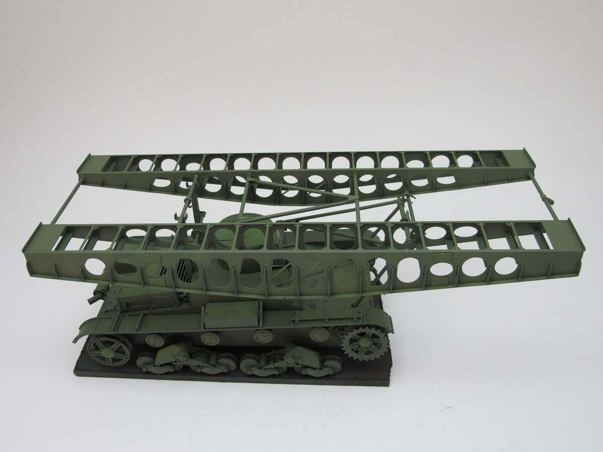
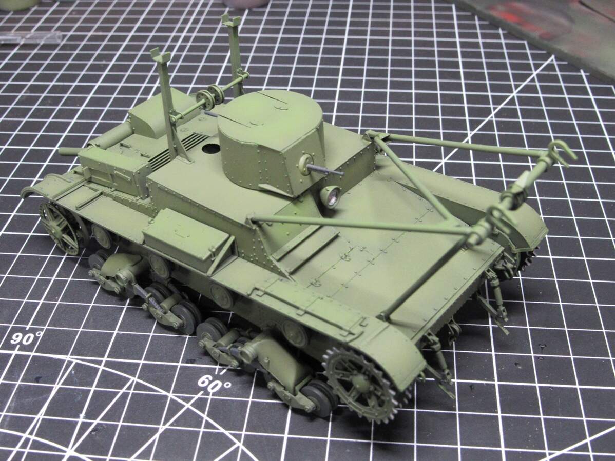
You know how you keep putting something off, and the longer you put it off the more daunting it becomes? That’s how I was feeling about finishing the bridge. Turns out, all I needed was some of the afternoon and evening to get it done. And once I got rolling I couldn’t stop, bridge done, mounted up to the tank and ran the cabling. Threw it in the booth and got some completed build pics (minus the tracks),
I plan on using these photos, warts and all, for when I list this kit (why I left the Fruils off). If I can get something presentable, than I think any other intermediate modeler can too. It’s still a bear of a kit, though it just takes some patience.
Hopefully get to priming tomorrow, I know I said It’d be tempting to leave the build as is, but now I want to see it with some color.
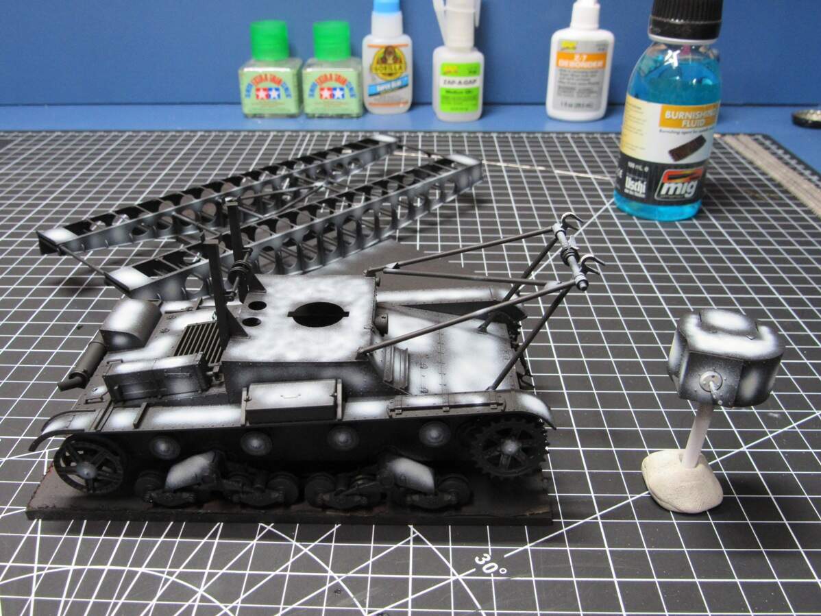
After much suffering I deep cleaned my airbrush and lightly polished the tip of my needle. It definitely sprays much better, and is now easier to clean. Still having a little trouble with lighter colors, but I probably just need to mix it better with more thinner. Feeling adventurous now, and plan to do some color modulation, nothing too stark as too much looks cartoony to me, but enough to add some variation. There’d be a lot of plain green otherwise.
Pics are a little washed out, needs to be back in the booth. That’ll probably be the last update for the rest of the week. Got a busy weekend, but next week I’ll probably get to oil weathering, and maybe the tracks. Got a thing of burnishing fluid a couple years back that I have yet to use, so something different for me.