Takom 1/35 AH-64D Longbow Start-to-Finish Build

My challenge is building this kit without the Longbow radar. There are no options in the kit to build it without. I can’t find a clear shot of what the top of rotor head looks like without it. (one grainy shot of just the flat top of the rotor head is about it.) The problem is they came in several configurations - flat top, just the lower cylindrical base for the Longbow, same base with a thin conical protrusion, or just a thin sensor mast. The last is what I’ll be doing. It’s what was most prevalent.

There are many other details in my photos that are different than the kit, but I’m not going to grouse about them. My son says the ones he worked on are pretty much like the kit. There are lots of closed over openings and vents in my photos. I’m thinking either due to higher operating altitudes or maybe dusty conditions. My son worked on them at Wheeler and in Korea, pretty much at sea level.

I sense another trip to 38-40-46.8080N 104-45-39.3800W. :slight_smile:

4 Likes

I will ask my buddy if he has any. Our guard unit just got some new birds a few weeks back. He is going also going next week to drop a 1/48 model built of their A version for display.

2 Likes

The last thing I want to do is highjack this thread with photos of my own build (we have another guy whose got that covered) but I did want to share.
Not all D models carry the Longbow. I think we all know that. In Afghanisatn it was found to be superfluous due to the kind of threats typically employed there. Even when using the Longbow, typically only one bird in four has one mounted. There were none at our firebase. So I’m guessung no one anticipated these words:
IMEX to the rescue!

I may have to lengthen the shaft,

but the part included in the IMEX kit should save a bit of scratch building.

Plus, I don’t agree with the color call out in the instructions for MIG Olive Drab Dark, so I"ll be using an IMEX kit to practice what may well be one of the most intricate paint jobs I’ve done in a decade or two.

5 Likes

I haven’t done any Apache work for a while. If you’re following along on the 5"38 project you can see why I haven’t. I also haven’t done any work becuase I needed those seat belts. Thanks to a tip from one of my readers, I got these on eBay and they’ll be perfect. We’re heading out for a week trip on Tuesday so work will begin again after that. They’re just was the doctor ordered as long as I don’t lose any of them.

3 Likes

Installed the new belts today and they are vastly better than the pathetic PE with the kit. I don’t know why Takom bothered to include it. It might have been better to mold them into the seats.

Here’s a nice comparison: I won’t tell you which is which. You can figure it out.

With the belts installed I was able to finally mount the seats. By default and installing the fancy seat belts, I’m saving my money and not spending $50+ on the wonderful Reedoak crew. I’m building the 5" turret and need to keep my powder dry to cover the costs of that project.

I then got back to work on the fuselage.

Based on Nigel’s video, he found that Part P25 which is installed on Page 20, must be installed on Page 5. You can’t put the duct assembly in place without P25 being in place, and it’s not an easy part to install requiring some pushing and shoving.

Here is part P25 glued to the exterior.

The fit was a bit ragged and needed a tad of filler. Then you assemble the 2-part duct and insert it from the rear. It’s supposed to nest tighly into the open space on the outside, but couldn’t quite get there. This is what the fit it looked like.

Here’s how it looked after filling and sanding.

And here’s the ducting on the inside. This ducting is for an APU and the starboard side is the intake I’m assuming.

There’s similar opening on the port side which I’m assuming is the APU’s exhaust. However, nothing is mentioned on page five. It shows the assembly going in on page 19 FROM THE OUTSIDE. Again, it’s tricky fit that would require handling the model a lot and there’s internal ducting (Parts C11 & 12) for this one too. I decided to install it now for the same reasons as the opposite side.

I assembled the three parts with the duct glued to the exterior fairing C60.

T DOESN’T GO IN WELL FROM THE OUTSIDE. If you do try and force it, the duct doesn’t bend around the corner and breaks the glue joint. Experiece talking. So I did it like the previous one and install the fairing on the outside and the duct from inside. Further reason to install in on Page 5. Page five is where you join the fuselage halves.

Here’s the outisde view: The duct has a tiny gap. I’m thinking that all of this is going to be hidden by the engine exhaust housing.

And from the inside.

The last thing I did was install the tail rotor gear box housing. You need to install this BEFORE joining the halves. It has a small fairing and a small PE screen that goes in. All this done before gluing it in place.

It’s installed in the starboard half. There is a plastic tail rotor shaft that also goes in before closing it up. I’m not happy with the plastic and may turn a piece out of brass that should not break when you look at it. The vertical fit is excellent. The fore and aft fit looks a tad long, and I will shave it down when it’s fully cured.ng. This is the insde view of the starboard half.

And the exterior.

We’re heading out for a week trip Back East, so any work will have to wait until then. Happy modeling!

9 Likes

I follow your progress with special interest… (I have one in my stash)

2 Likes

Hey gang… I’m back.

My last post was in August 2023. For those that weren’t following this next project, here’s the final result.

The model is a cutaway of the entire 5"38 Caliber Mark 28 Iowa-Class Secondary Battery from gun house to magazine three decks below. It will be joining my model of the 16" gun system in the Ward Room of the Battleship New Jersey Museum and Memorial berthed at the Camden, NJ Waterfront. Right now the Big J is in a dry dock at the Philadelphia Navy Yard to have its bottom painted for the first time in 34 years. It will return to Camden before the 4th of July. I will be delivering the model in the first week in August. This model, was supposed to incorporate the 1:35 Takom 5" turret plastic model, but it was no longer available and I already committed to the ship to build this, so I changed scale to 1:48 and scratch built the entire model.

No commercial parts whatsoever. Every part was drawn, printed, crafted and/or assembled by me. I had only a few dimensioned drawings. Ryan Syzmanski, the Big J Curator, was able to feed me pictures and measures that I needed for more esoteric features.

The magazine is located three decks below and offset towards the ship’s interior and well within the armored citadel that characterizes these ships. It was a challenge to show it while maintaining this relationship. Drawings I’ve seen eliminated the 2nd deck making it look like the magazine is much closer.

But that model is built and my attention is turning back to the apache.

Today, I got the fuselage closed and was pleased by the general fit of the Takom kit. it was much better than the Kitty Hawk Seahawk I had completed earlier.

Almost no filling is going to be needed on the model. The tail fit nicely as did the joint at the front.

Likewise, the two bottom panels went on very tightly, Tamiya-like.

Lastly, I assembled the wonderfully-detailed the 3D printed Reskit Chain Gun. I’m pretty good at 3D printing. These guys are working at another level. I would like to see what machinery, setting, etc. they’re using. I get some amazing prints, but they are just a tad better than my best. That said, it’s a fairly brittle resin and you have to be very careful removing the supports. One of the guard rails broke and I repaired it with Bondic. Bondic is a similar UV resin as they use to make the parts and welds parts together or fills holes. But you must have a way to shine the curing UV light on the resin. If it’s buried in the joint, it will not cure. The heat shield of the barrel is actually proud of the barrel!

This very delicate part will NOT go on the model until very near the end. Otherwise, I will break it!

I want to finish this model so I can bring it to my friend from the old neighborhood during the same trip as we deliver the ship.

11 Likes

Glad to see you back!

Good to see you back working on this. It is looking great.

Some caveats… I’m not intending this model to be a show entry. It’s for a friend who’s into this aircraft, so it’s going to be “mostly” out of the box. I use quotes because I’ve already added that Reskit Chain Gun. It’s having exposed engines and then all the piping that I can add if I was so inclined. It’s the same powerplant as used in the Seahawk, and y’all know what i did to that one. It got a silver metal at our Regional adjudicated show last September. This one is not going to be that spectacular. That said, I have AMS and therefore, can’t be held responsible to any sudden urges to super-detail stuff.

Yesterday, I got the front optical sighting system built. I inadvertently cut off several nubs that I mistook for sprue remains that were in actuality alignment and pivot points. I fixed one by substituting a metal rod all the way… a much better solution anyway. For the other I put the part in from the front and managed to position it well enough.

First the metal rod substitution.

The male pin was on the top of 1/2 of the drum. I filed what was left of it level with the surround surface, made a center punch mark with an awl and then drilled it all the way through and out the other side so the rod would be properly aligned.

The bottom had a female divot which was supposed to be captured by the pin in the bottom bracket. It was very dubious. With the metal, it ain’t go’n anywhere.

The lens on the top optical unit had two side bumps that were to key into respective divots on the two plastic shells. The instructions, which I didn’t read as thoroughly as I should, showed the plastic lens being attached to one side and then captivated by the other. I glued them together first thinking the lens went in from the front as the other two, and left the bunps on, only to find that I couldn’t pass the lens through the opening because the bumps got in the way. I filed them off and spent way too much time positioning the lens in the opening. It kept flipping or dropping inside. Persistence won the day. I used Testor’s Canopy Cement to hold all the glazing.

For the telescopic optics. I painted the chamber flat black. When dry went over the lens areas with Dull Coat to seal the black. Then applied Molotow Chrome and let this dry.

I added clear green and a mixture of clear red and blue to the two lenses. That ended the session.

The glazing for this one goes on next. I’m deciding on how to mask them. I’m vascilating between liquid mask or trimmed Tamiya tape. I’ve had mixed results using either method. Should have painted the insdie of the larger opening flat black. Didn’t realize you could peer into that space.

7 Likes

Masking problem solved. Mask set I bought has masks for all the optics lenses. Once in a while you win one.

1 Like

Had a week off… not by choice. Two weeks ago, I had a normal Medicare Wellness Checkup. It was PERFECT. All the numbers were centered in the green. I’ve been quite healthy lately without having a cold in almost four years and the mildest case of COVID anyone could ask for. My doc suggested getting an updated pneumonia shot, PCV 20. I normally have no reaction to vaccines.

That was on Wednesday. Friday night my wife and I went for a walk. I was more tired than usual at the end. Saturday night it started in earnest. Ran a fever, had terrible chills, headache. Fever got worse over the next two days, and then I got a rash on most of my abdomen and extremites. Then a tight chest, light cough, bloody nose, etc. I went from being very healthy to being completely miserable.

Went to the doc, had blood work which showed systemic reaction to vaccine. Got steroids. Slowly, things began to normalize. it’s been 10 days and I’m almost back to normal. RIDIDCULOUS!

It seems I have “serum sickness”. It’s an identifiable immune response to a specific protein antigen in some medication. Usually it takes two weeks to show up. However, if you’ve been exposed to this antigen in the past, it can take 2-3 days… just like me. It self-cures, but don’t have that vaccine again! Most likely it was because I had Prevnar 15 a few years ago. My doc and I need to find out specifically what caused it, since other vaccines may have this protien also.

So I’m finally back in the shop and got some Apache work done.

The mask set (AllScale from Czech Republic) is very precise. There are masks for the interior and exterior of all glazing. The interior frame has rounded corners reflected in these masks.

And the outside masks have squared-off corners. There was just some tiny trimming needed on a few edges with a brand new #11.

I airbrushed the interior frame with NATO black. I was able to remove the masks on the side glass, but left it on for the roof glazing until I got more detailing done on it. This is a model for a friend and not going to be a contest entrant. Therefore; I’m going easy on the detailing. To that end, I’m leaving off a lot of the doodads inside the cabin roof, and I’m not opening the doors. The model is much more secure with the doors in the closed position. With them closed, the roof is hard to view and therefore, I’m leaving stuff out.

The roof does have some hand holds. (4). I used a J-B Weld Structural cement since it works well with painted surface and doesn’t craze plastic. I had three installed and the four was just sitting on the bench in front of me. THEN IT WASN’T! Gone! I made a replacement out of 0.020" phos-bronze wire. Glued it in, and then… one of the plastic ones I previously glued in was now GONE ALSO! What the heck! Made another metal one.

This glue takes several hours to fully set up, so I’ll install the glazing tomorrow. The decal set, as I noted last post, had masks for the front optics.

I then glued this assembly onto the nose with good ole Testor’s tube cement, which works well on slightly uneven joints.

I entertained the though of filling that seam, but then after looking at some prototype images, found that it’s not a very tight seam and I left it alone.

More assembly and painting will go on tomorrow.

8 Likes

“then it wasn’t”-we’ve all been there!

Worked today… well… sort of… spent half the time searching for a part. More about that later.

Got some smalll details put on the roof and proceeded to damage the small vertical antenna. So I cut it off and will replace it with music wire later on. The other detail also got whacked, but survived.

With the top roof’s handles secure, I glued it in with Tamiya liquid. Front and back went in nicely. There part over the mid-tub armor panel was gapped and needed some special attention.

I glued in the pilot side glazing using Testor’s Canopy Cement. I like that stuff since it does hold reasonably well, can clean up easily, doesn’t craze and, G_d forbid, you have to remove the part, you can. Today I did. A couple of pieces of tape held it in place until it cured.

The Strb’d side needed Part P53. It’s specifically shaped filler piece that goes in between the moveable frames and has provision for a hand grab. I cut off one end, and when the other end cut… whoosh! Gone! It took off to the left in an elevated trajectory. I didn’t expect this part to be a flyer. I didn’t hear it land anywhere. I usually try and listen if a part hits anything.

I cleaned and emptied EVERYTHING. I checked my clothing, shoes, etc. I emptied a chaotic box of scrap wood and junk under the workbench (it needed it anyway… badly), swept everywhere, checked every nook and cranny of my other main workbench. This puppy was in the multi-verse.

So I fabbed a filler piece and glued it in. It lacked the surface details of the real thing, but did the job. It wasn’t as easily as it looked since the slot was not uniform width all the way down.

There was also some gapping at the top of the front glazing and I filled this with styrene to be trimmed later.

I started working on the two sponsons. I’m not opening the equipment bays. My friend is not a critical model observer and I don’t want to spend the many hours to detail these areas if they’re not appreciated. Furthermore, I have some big stuff in the queue and want this model done by the end of July when I deliver the turret model to the New Jersey.

It was quitting time (5:00) and when changing out of my shop shirt, I reached in the pocket and guess what I found? P53! I swear I checked that pocket early on in the search. Absolutely drove me nuts!

Brings up being able to rip out work when glued with canopy cement. I removed both glazing pieces and will install the correct part tomorrow.

10 Likes

I’m bringing this model to Philly with me when I deliver the turret model. I’m building it for a friend. If you choose to build it with blades folded you have to leave off the Long Bow radar. The folded config is only used when airlifting or shipping the Apache. And the Long Bow would create head room problems. It’s an entirely manual affair, unlike a Seahawk where blades are routinely and hydraulically folded for shipboard stowage. It would be easier to build with blades extended since the folded blade support system is finicky, complicated and looks a bit frail. I know that the Seahawk’s support frame was a fragile mess that kept breaking right up the show last September when i got a 2nd place award for Helicopters. That said, I don’t believe my friend has the display space for a 1:35 Apache with it’s full rotor width.

Today, I glued the errant part P53 in place.

I cleaned off the dried canopy cement from yesterday’s attempt and then reglued the glazing with the P53 properly seated below the glazing. It’s why the glazing had to come off. The glazing sits on a lip on the P53 which had to go in first. There’s a lot to do before O.D. goes in on those windows. I trimmed those styrene strips in prep for painting.

Got back to work on the sponsons. There’s two PE grills that go in on each side which are retained by a narrow plastic frame. Went in without too much fussing.

I read and made notes on all the review builds of this kit. One of the things that caught my eye was installing the stub fins now instead of much later in the assembly. If you wait, they will not go on! The fit is nested within the sponsons so you need to do them sort of simultaneously. I assembled the two wings and did some trial fits to the fuze. It’s a very tight fit. They also say that it’s wise to slightly thin the wing’s broad tab so it’s a nice sliding fit. Right out of the box it’s almost a press fit and all that pushing and shoving can lead to bad things.

Here’s the port side wing alone. That upper fairing is a separate part.

The upper fairing completely fills the opening on the sponson and would be very difficult to install if the sponson was fully glued in place.

And here’s the sponsor during a trial fit. The Takom kit has very nice Tamiya-like without needing little or no filler. This is the strb’d side. Can’t glue this in yet. You have to capture the main landing gear inside before buttoning up. That, of course, complicates things. I purposefully clipped off the pitot tube since it was bent sideways. I will replace all these tiny tubes with piano wire later in the build…

9 Likes

Got the sponsons installed. It’s a very challenging aspect of the build and lots of folks have written about it… including this author. It’s theoretically a snap fit, but to accomplish that you much manipulate many things at once. Before that I replaced one of the pitot tubes with an assembly of Albion Metals telescoping micro-tubing. It’s all held together with thin CA. I have this tubing in Aluminum and brass, and it’s very useful in making miniature pipe fittings for super-detailing jet engines.

The main gear is a challenge. The oleo strut should glue into the bracket on the main strut, but immediately I pinned it. It has to be flexed a bit getting it into place and having this joint movable is necessary (just like the 1:1). You also have to reduce the size of the half-moon pin. It has to engage in a similarly shaped hole in the fuse. It’s a blind fit and if you have to push it in (or worse… if it doesn’t go in) you will break something.

The gear is installed in two locations in the sponson. They are not particularly secure and even with gluing, tend to come apart when doing the final asssembly. There are some tiny parts that attach to the gear that you leave off at this time. They will not withstand the handling that follows. You can add them later if you’re so inclined.

The pushing and pulling I did during my attempt at installing the sponson, broke that lug. It, however, wasn’t critical and the gear is secure anyway.

You have to coordinate three things: getting the gear into their respective mating spaces in the fuze, getting the stub wing settled in, and pushing the sponson onto three large openings that correspond to the big pins in the sponson. The Stub Wing’s very tight fit into the sponson greatly limits fore and aft degrees of freedom. You have to get all the pins into all the holes, even though some are completely out of sight. And you must do this without applying undo pressure.

This whole deal took a lot of time. I was getting frustrated and was thinking of building it without landing gear, but the Apache doesn’t have retracting gear so that possibility was moot. I perserved! Eventually it snapped in place. I ran a stream of glue (Tamiya) around the entire perimter. The fit is amazing.

Peering into the innerds, you can see the sponson-side mounting lug. You cannot see the fuze side which makes this whole affair so confounding. It’s also why that pin must be reduced in cross-section so it drops into its hole. You can’t force it!

Now… with all that said, the second sponson dropped into position almost instantly and snapped solidly in place. Don’t ask me why this happened or what I was doing wrong with the first side. I have no idea! As Mark Knopfler says, “You can get lucky some time.”

So here were are as now. Notice I broke off the Long Bow mast… AGAIN! I had already glued it with metal reinforcement. It broke right at the end of the metal rod. This time I’m going to replace it all with metal if I can. I hate long plastic shafts like that. I always break them during assembly when I’m doing something else on the model and holding it wrong. I’m waiting to whack the tail rotor shaft. Don’t know when it’s going to happen, but I am sure it will. I should replace it with metall before it happens.

8 Likes

Lots of diffierent things going on today. Before I get into that, my wife had radical breast surgery in January after a cancer had returned after 16 years. She had chemo afterwards to reduce the possibility that any renegade cells got away. Then last week she had a followup bone and CAT scan just to make sure nothing was going on. The CAT scan found a 1cm “Enhanced Nodule” in her liver. Panic ensured. She had an MRI to confirm what it was (or wasn’t) at 8 p.m. on Saturday night. Today we got the good news. The 8mm nodule is benign, basically harmless and will never turn malignant. We needed that good news!

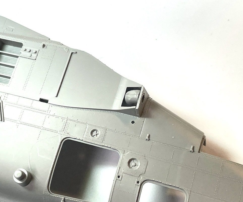
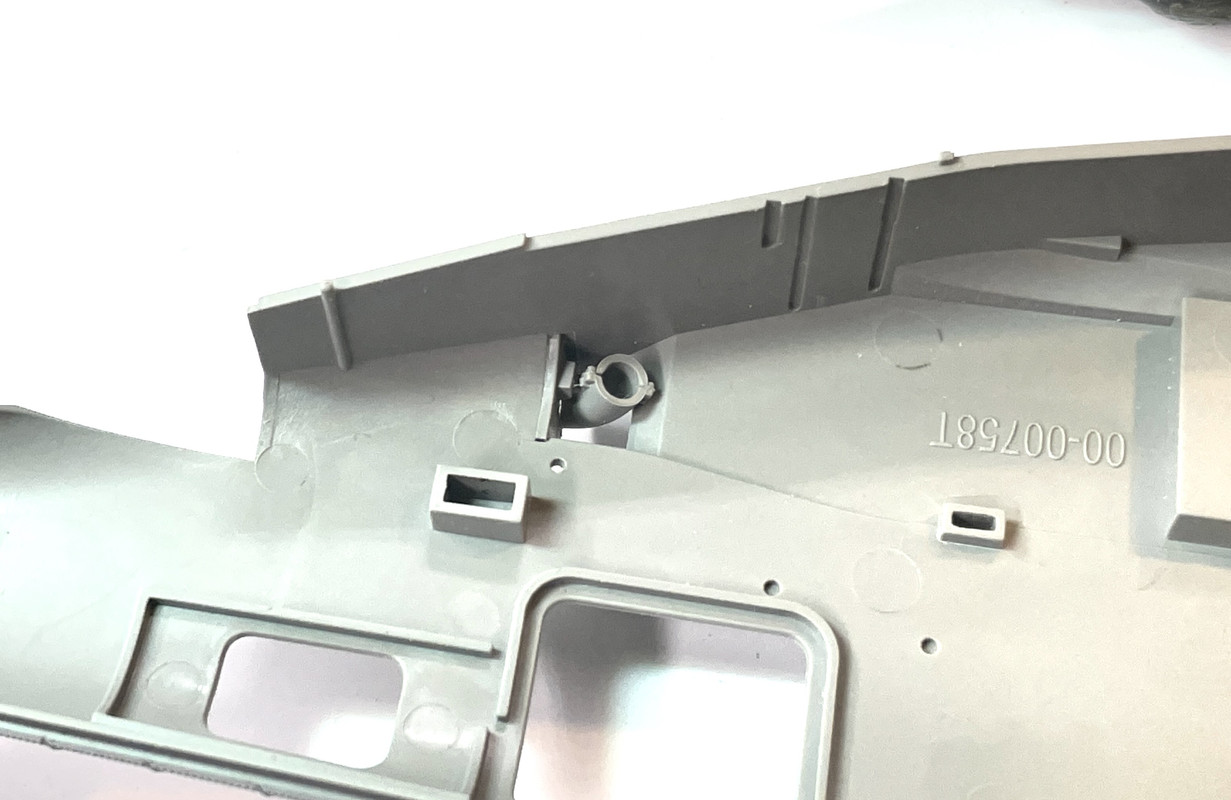
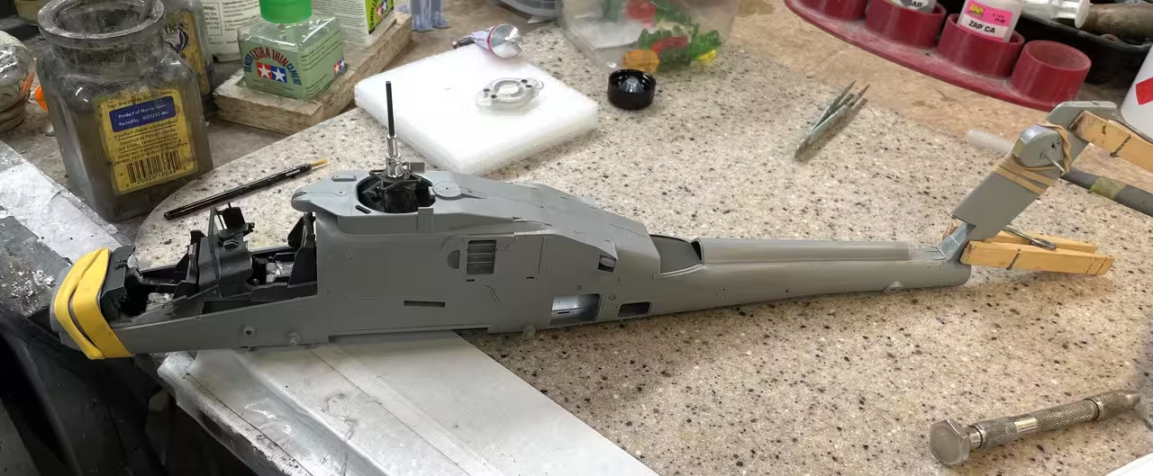
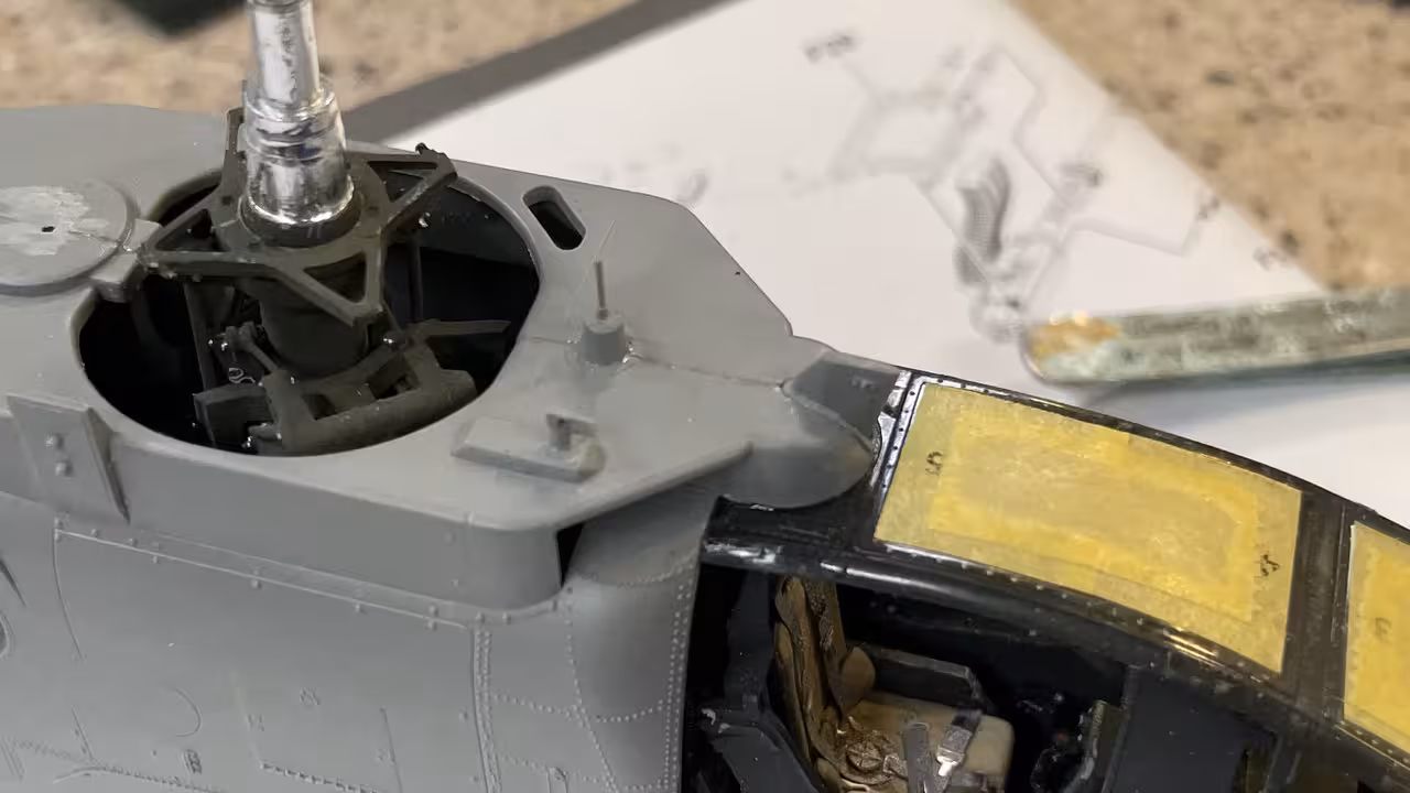
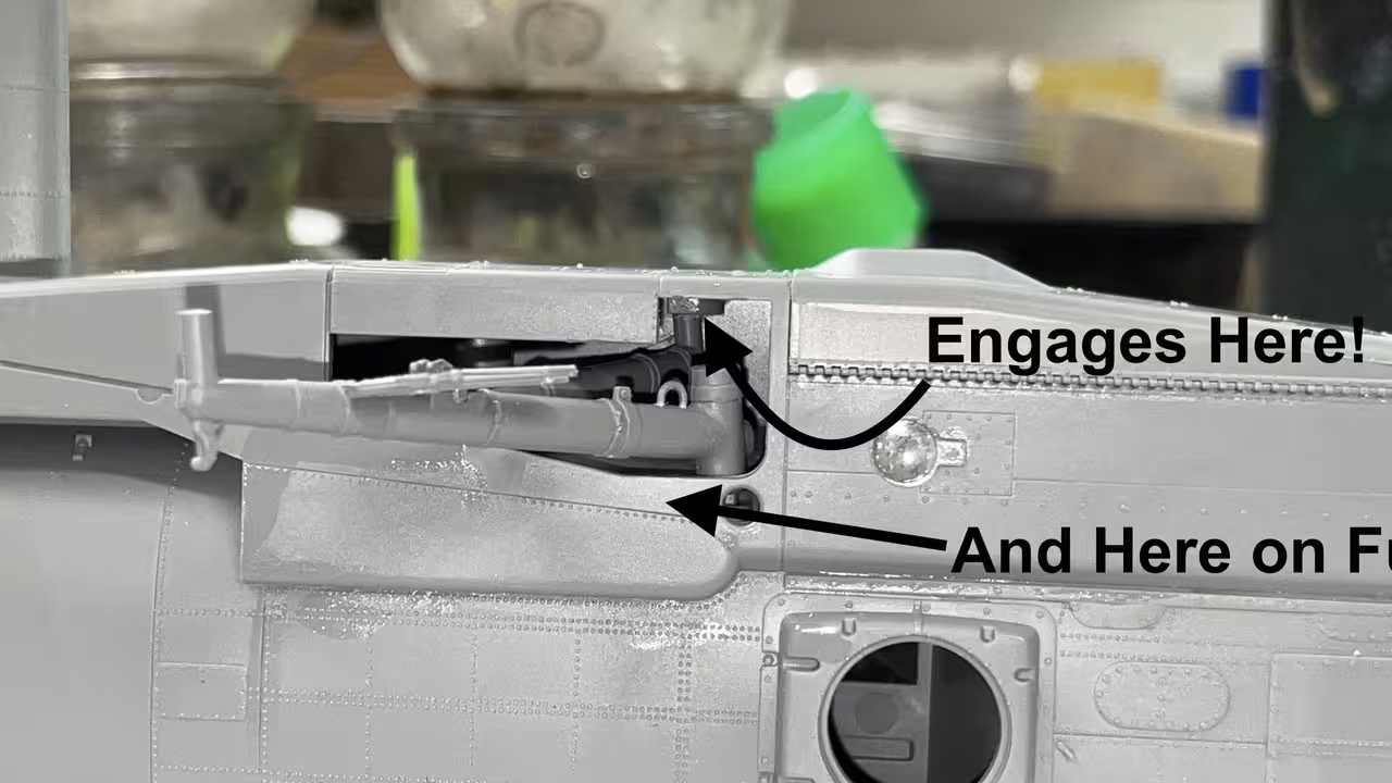
First thing I did today was make a brass sleeve that will positively connect the broken mast section to the existing stub. I will modify the part that joins here so it accepts the sleeve.

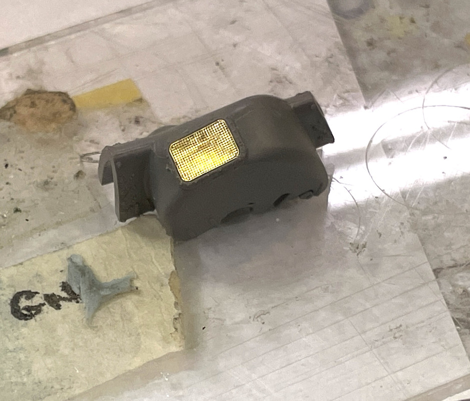
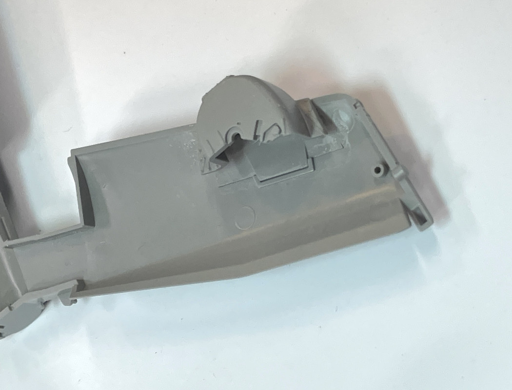
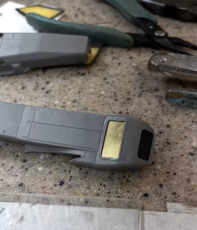
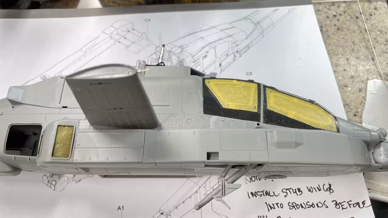
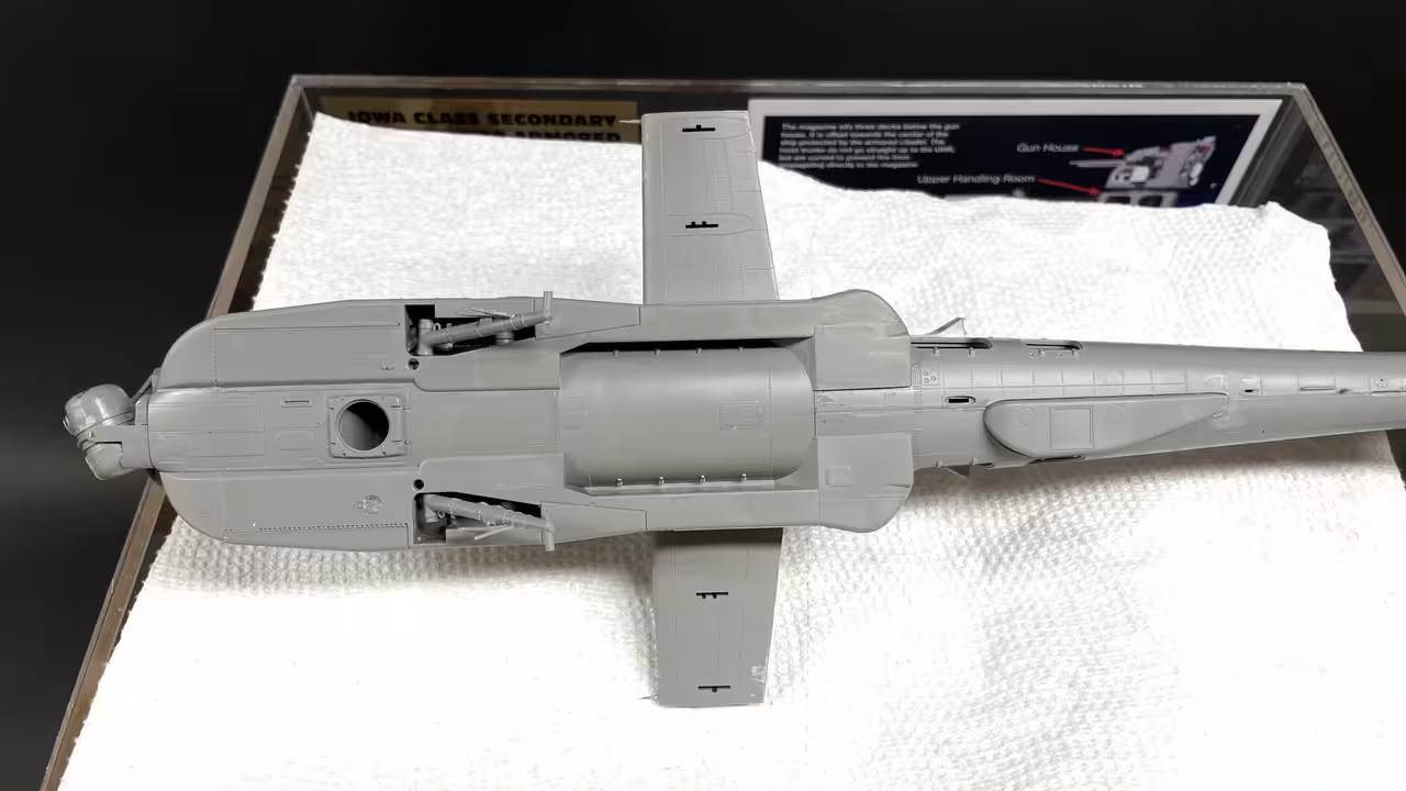
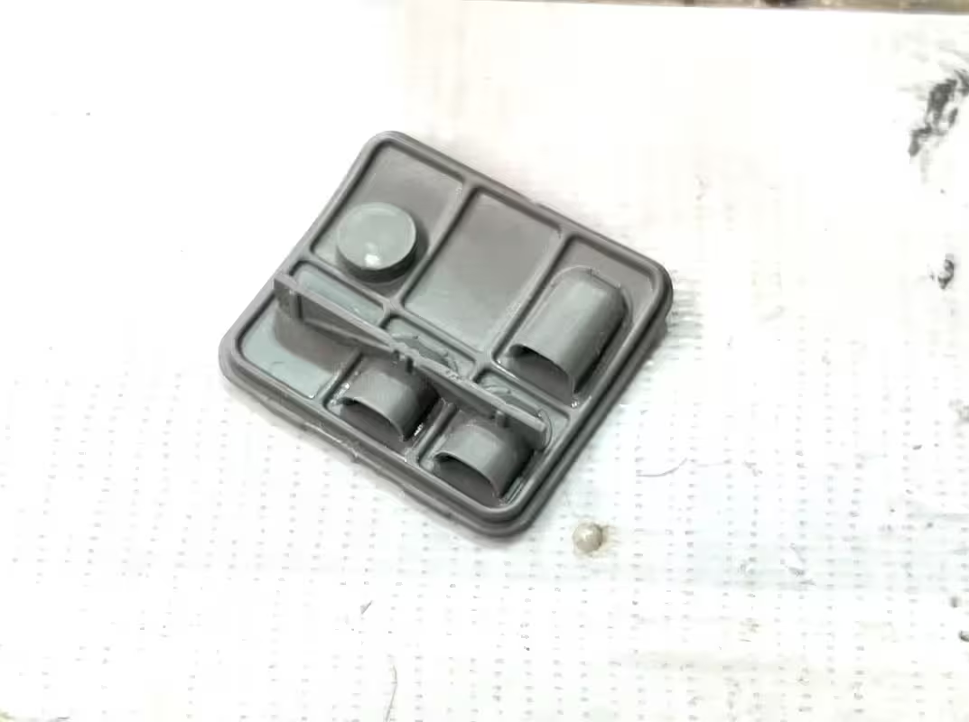
I then started working down the port side putting in the various and copious details contained in this model. The first was a grilled access cover. The instructions call out some internal pieces… you will never see them so I didn’t include them. The grills are on PE Fret A. There were three of them.

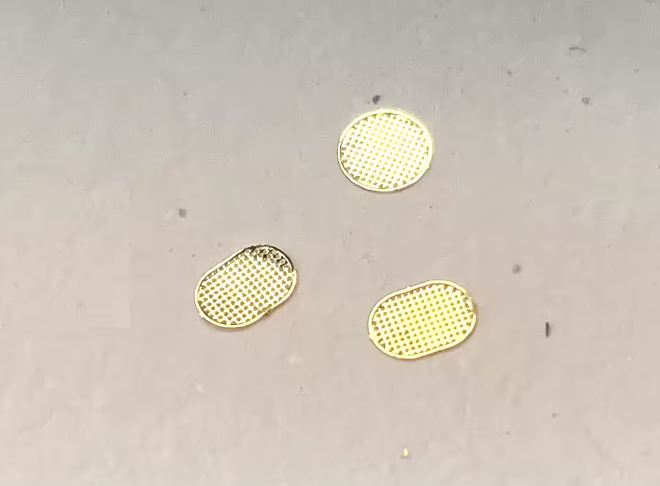
I installed them onto the part before gluing the door to the fuze. I used Tamiya Gel CA. Gel CA gives you a lot of working time, doesn’t wick where you don’t want it and cures quickly with a tiny bit of accelerator when you’re ready for it to set. The round one got a little banged up in this operation.

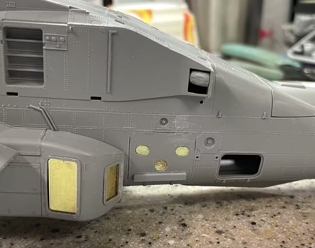
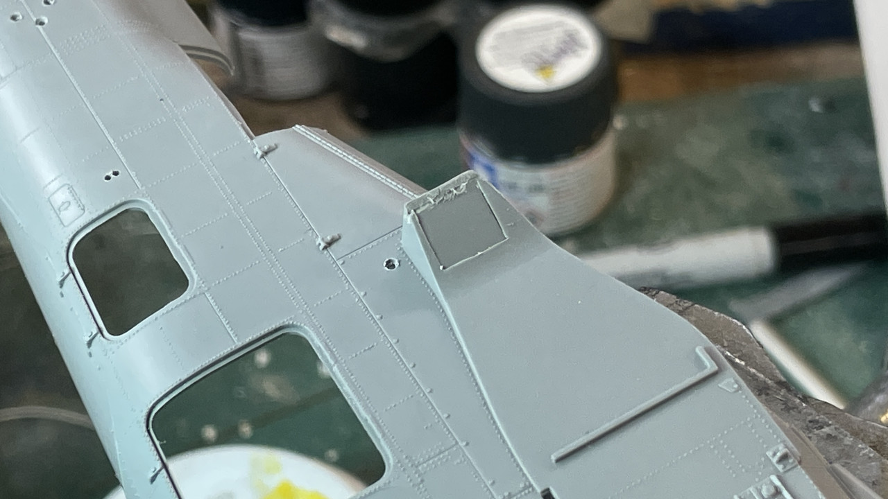
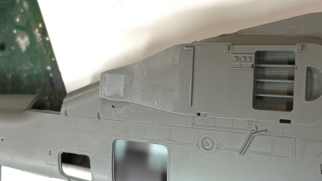
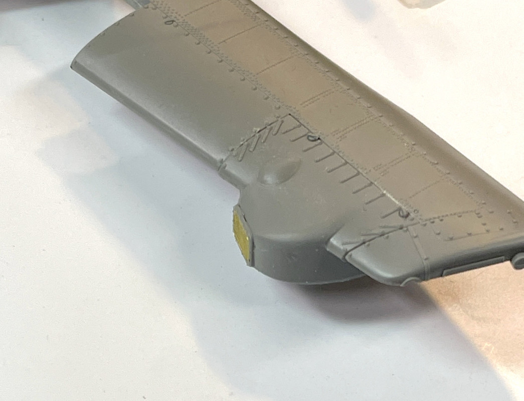
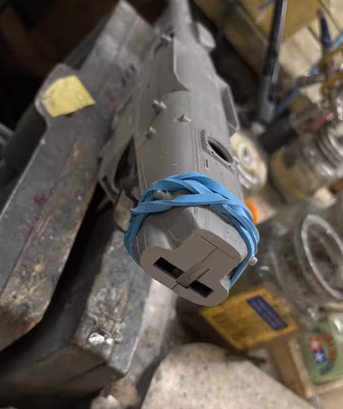
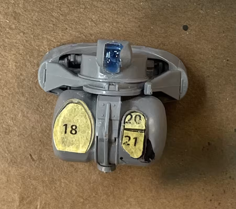
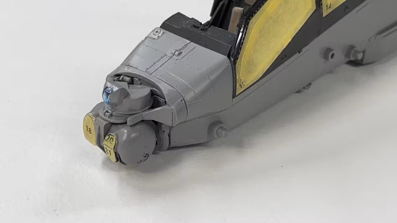
Next up were mounting blocks for some countermeasure sensors. Takom couldn’t just injection mold the part with the bolt patten behind it. Nooooo… they had to have a PE flange that sandwiches between the two-part styrene and the fuze. This precluded using Tamiya thin cement to do the gluing, which was now done with gel CA.

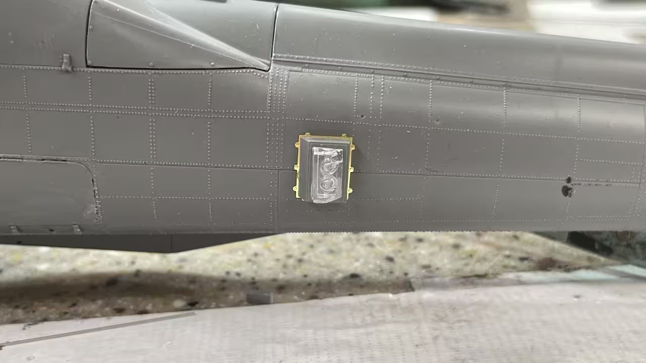
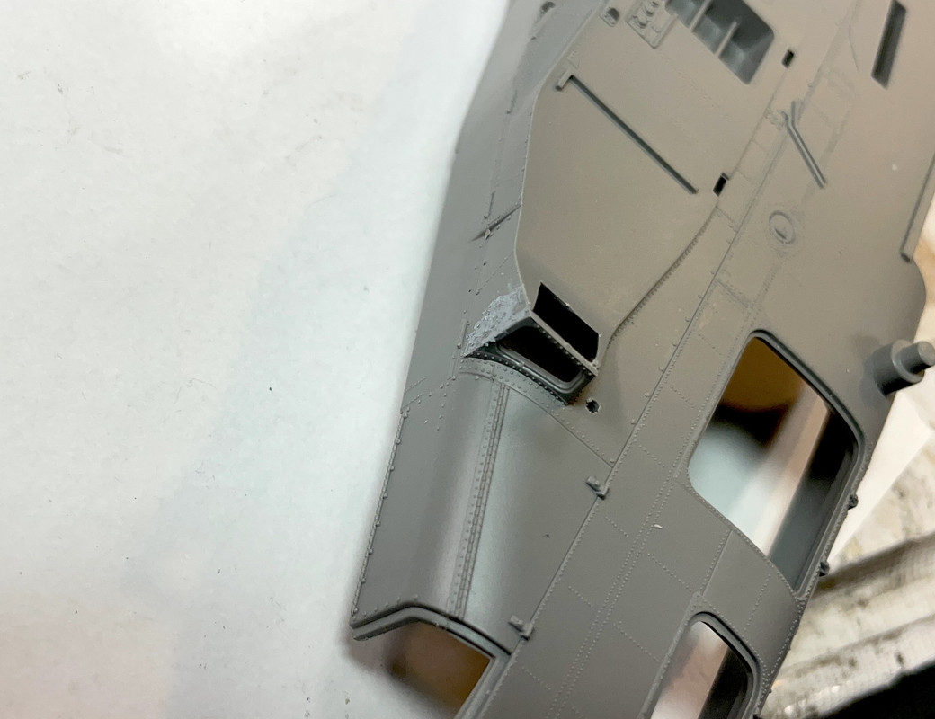
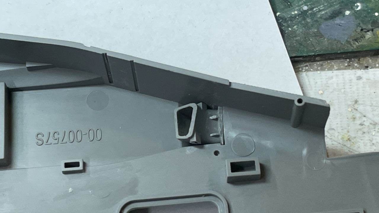
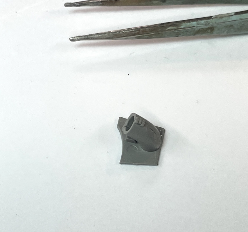
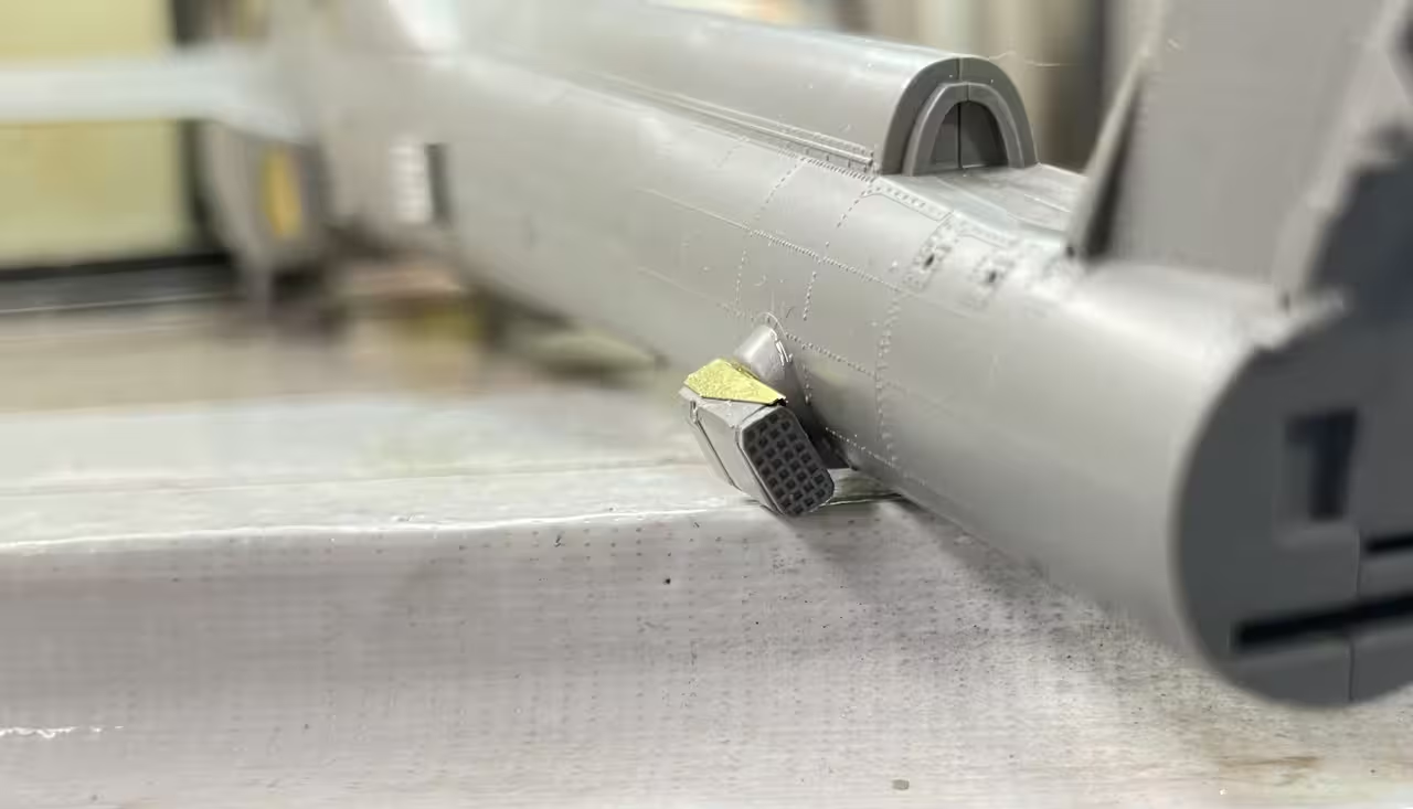
And then there was another styrene/PE composite part with this odd, rear-facing vent… Anyone know what it is? Tail rotor Oill Cooler??? And again, had to put it togther with gel CA. I used the Small Shop Little Bender for this small PE job.

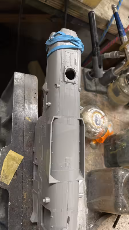
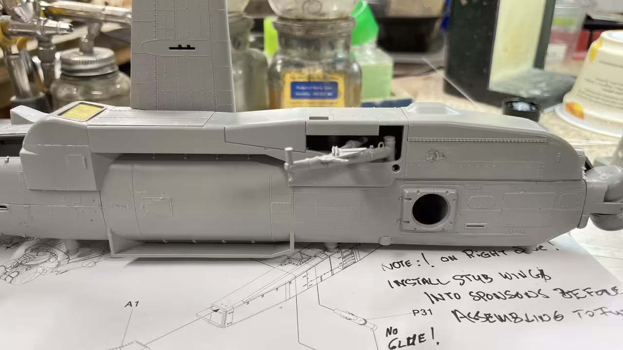
That finished the port side for these things. The starboard side has similar components. In this case, just for fun, I added the internal, unseen details on the access door.

Lots of stuff and a waste of time unless you like gluing stuff for fun.

This side had it’s own passel of PE grills.

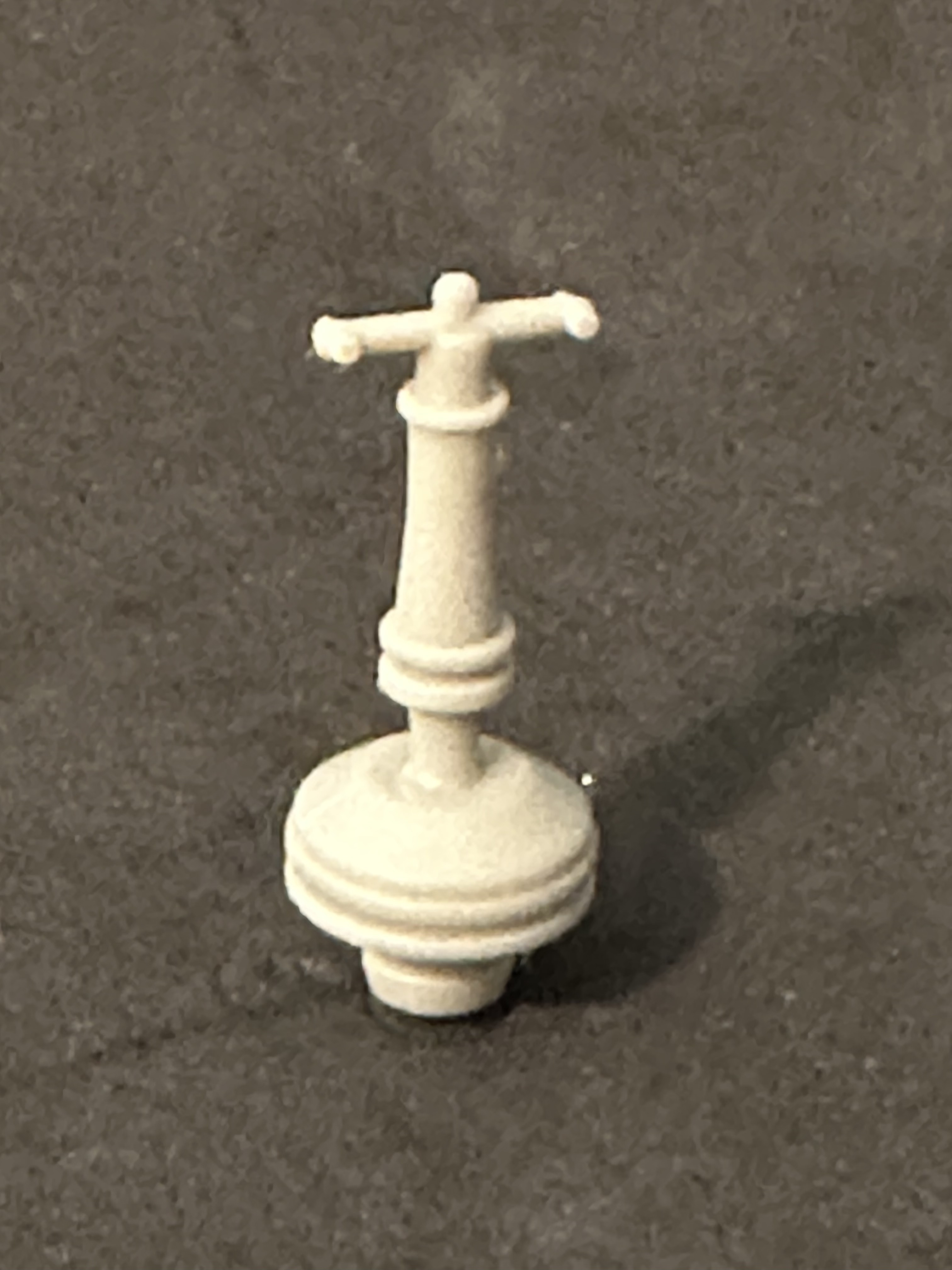
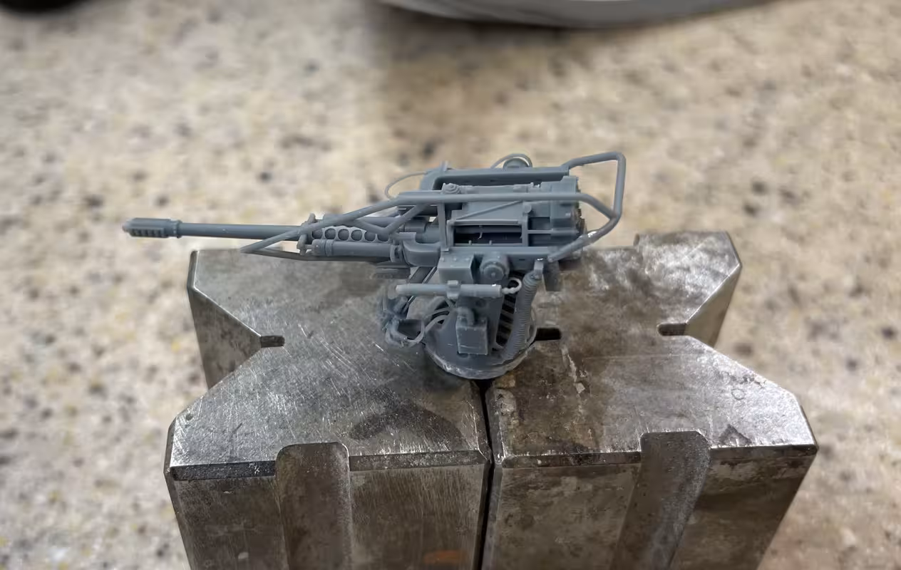
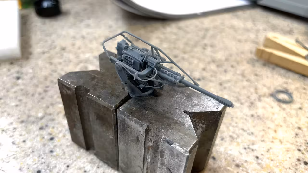
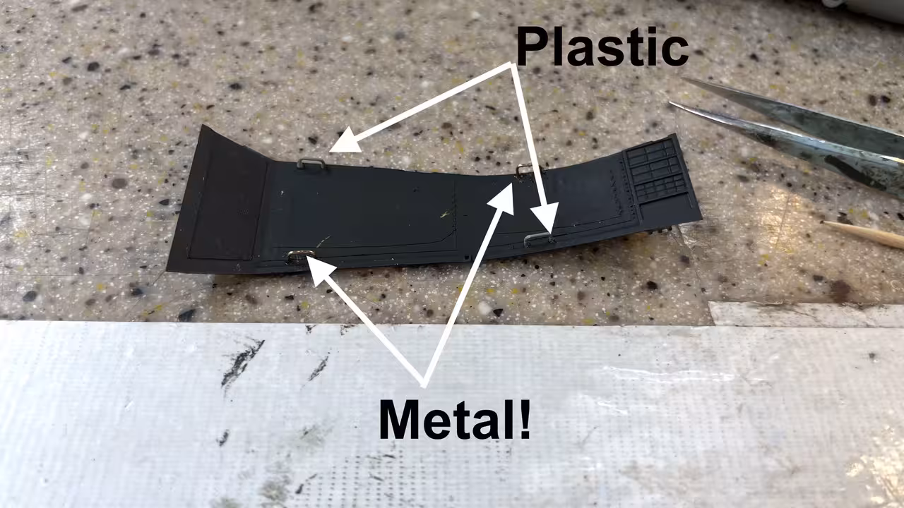
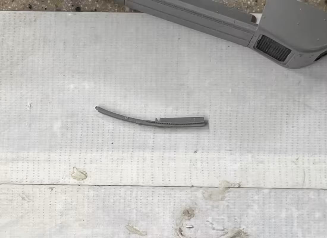
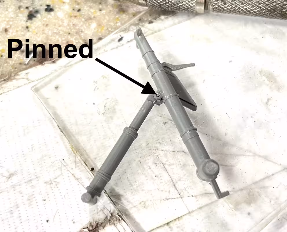
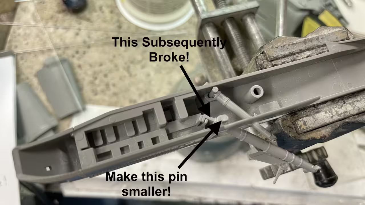
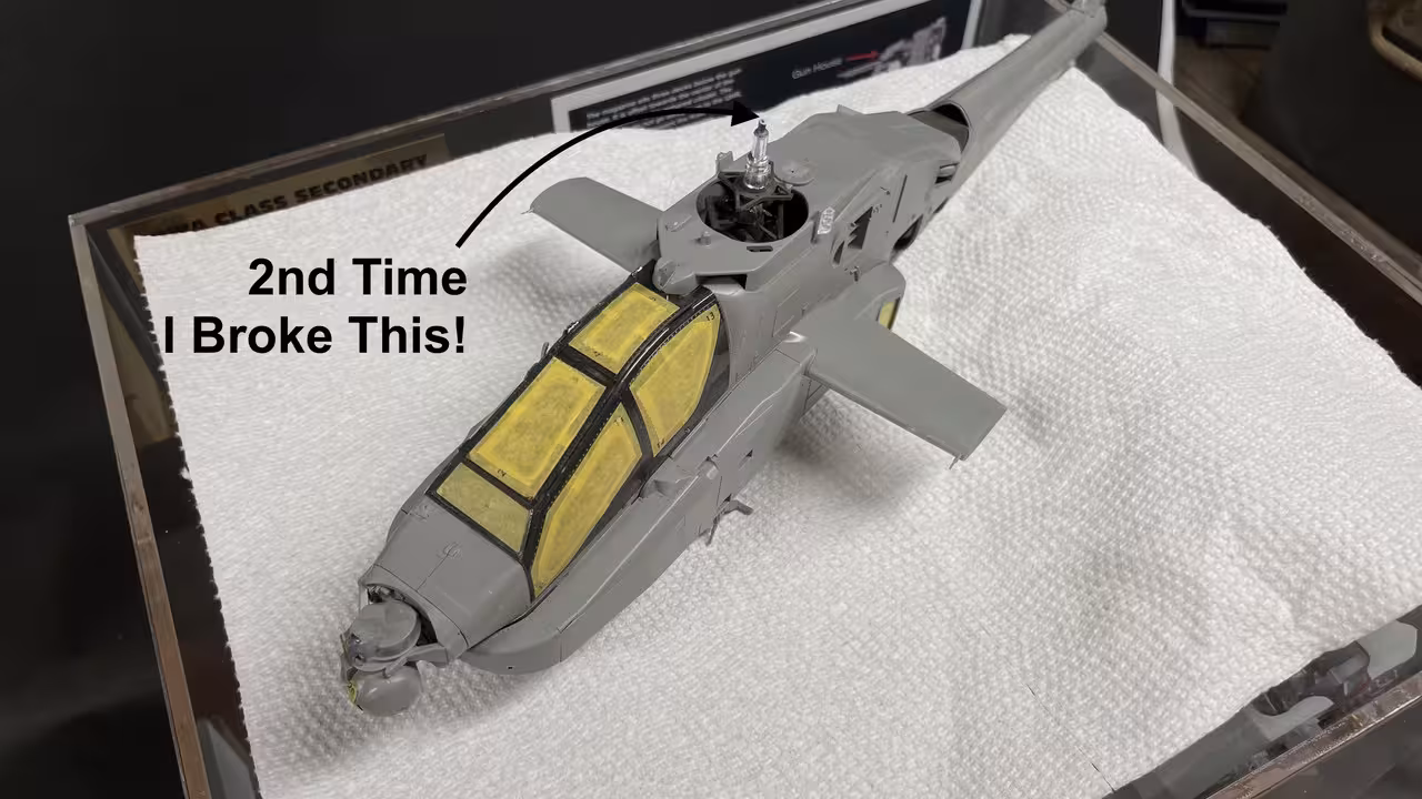
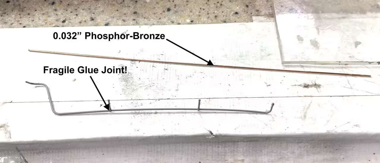
This step also called out of a very frail, 2-part, styrene antenna structure. I didn’t give it a second thought. I was going to replace this part with metal. It wouldn’t last five minutes with the way I build models. It measured 0.031" in thickness, which is very closse to 0.032" wire I have. I have an American Beauty Resistance Soldering Unit that makes putting together precision soldered assemblies enjoyable.

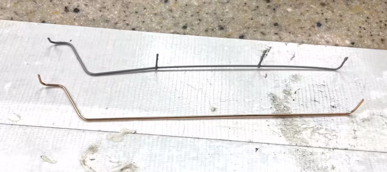
Holding the stock against the master I marked where the bends would go and use a jeweler looping pliers to give smooth and accurately placed bends.

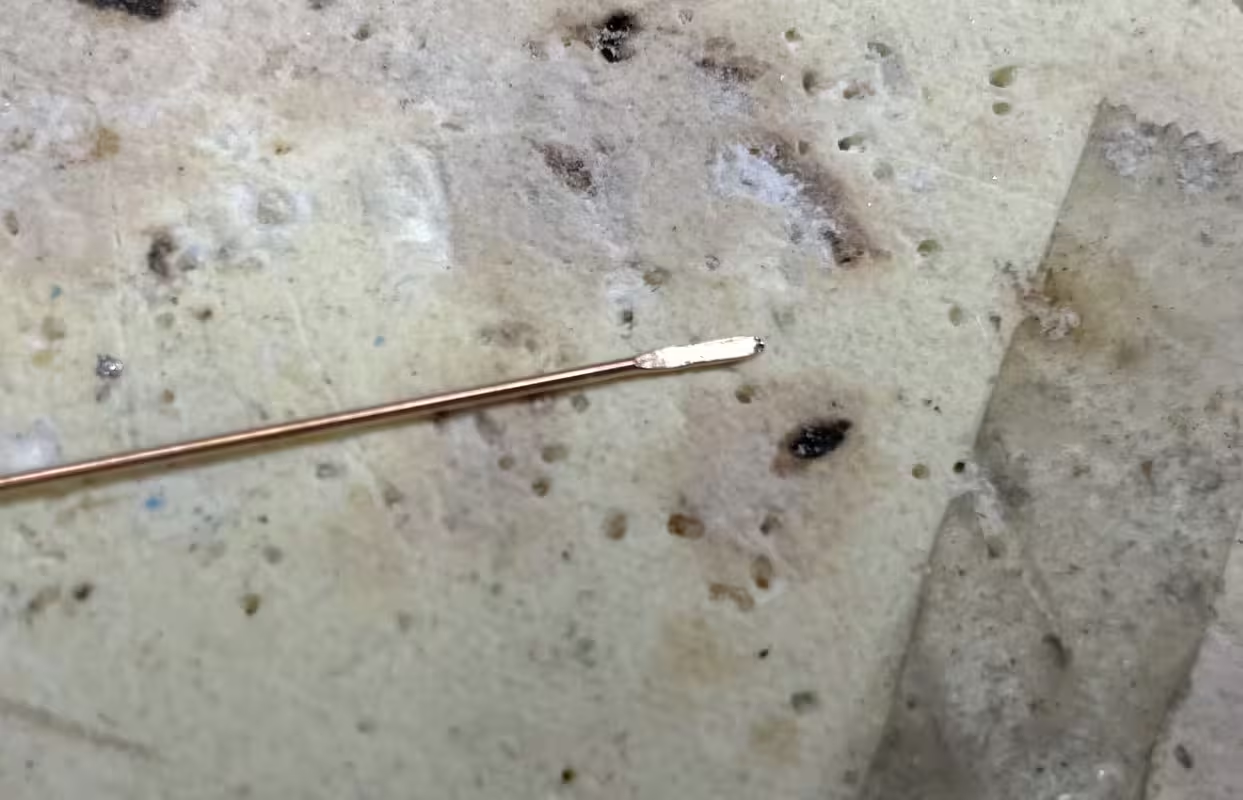
For the support brackets (also measuring the same size), I first flatten an end to form the attachment loop. I use a very old, very strong, very reliable Vise Grip, that must be from the 1960s (my dad’s) and with the jaws at fully-closed locked position, keep squeezing the stock and turning it over and using the side entry and front entry to the jaws to get it as flat as possible.

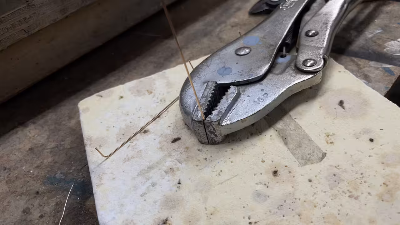
Here’s how the flat looks.

After forming the loop, trimming any excess preventing full closure, I trapped the rod in the joint, and then, using a MicroMark ceramic soldering pad, setup the job to be soldered. With the RSU, the joint is made in seconds. I use very fine gauge rosin core solder (.5mm).

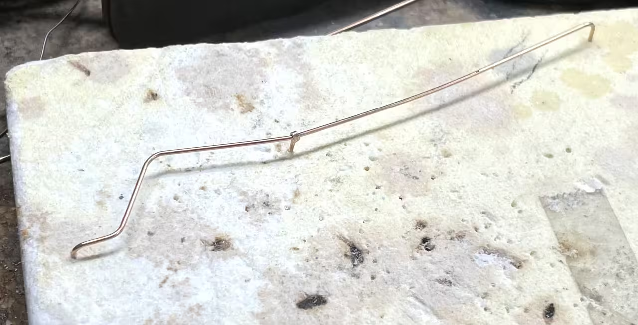
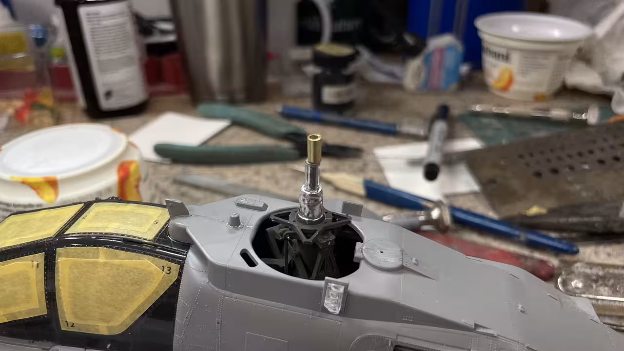
I’m pleased with the final result, and although it might miss some small details, it will survive handling and the 700 mile trip.

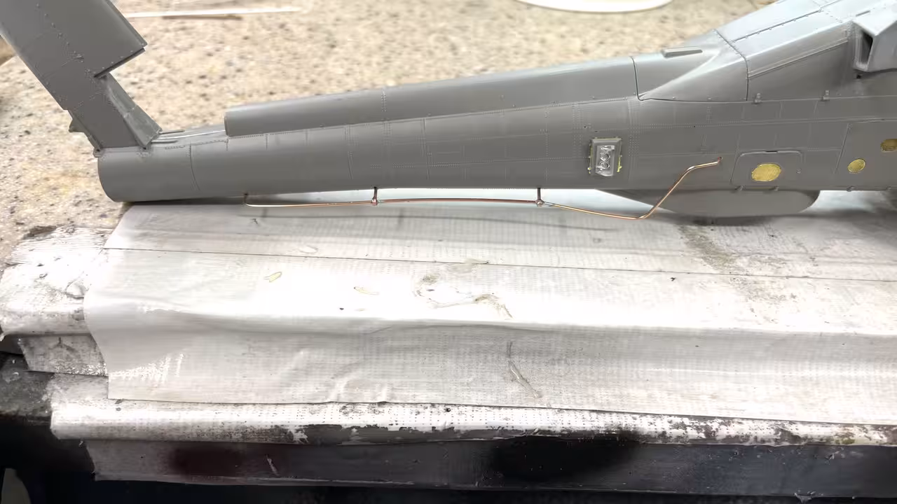
I have some 3D printed fitting that I’m going to use for the right end. There’s a plastic kit part that was supposed to glue there, but I’m going to change that.

So it was a pretty good work day…

7 Likes

That is good news on your wife. Oh, the metal antenna looks great too. :+1:

2 Likes

Good to hear! :newspaper:
+
Good to see! :hammer_and_wrench:

—mike

1 Like

Has anyone tried building Meng’s version?