Takom 1/35 AH-64D Longbow Start-to-Finish Build

Thank you! I had 3D printed some 1:24 pipe fittings for last years NASCAR car build and I was able to put one to use as the fuze terminator for the new metal antenna.

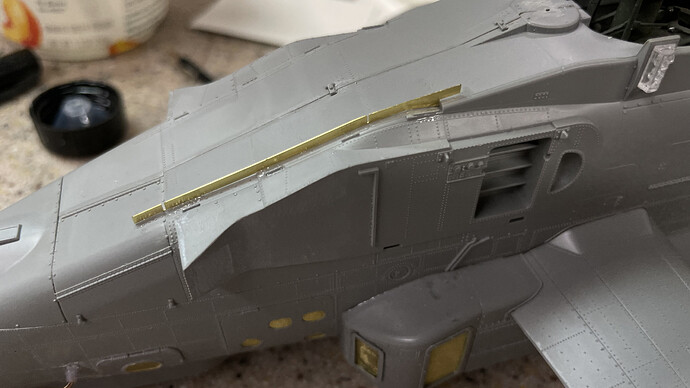
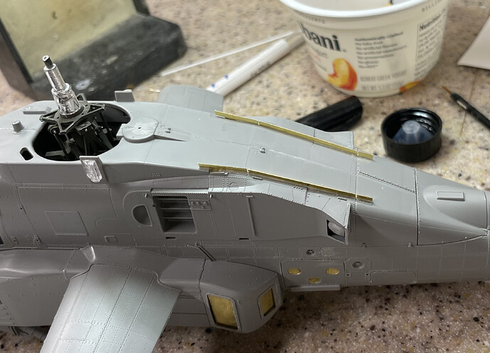
I then installed two ridiculous PE ribs that adorn the top of the fuze. I hate gluing this on a 0.005" edge. I used a combo of J-B Structural Cement and CA in that order. The J-B will hold a bit longer and more secure to the metal/styrene bond, and the CA helped hold it all in place until the J-B sets (which is sloooooowwww). The first one was a bit of a fuss.

The second one was much easierā€¦. learning curve. If I had to do a third it would even be better.

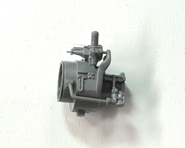
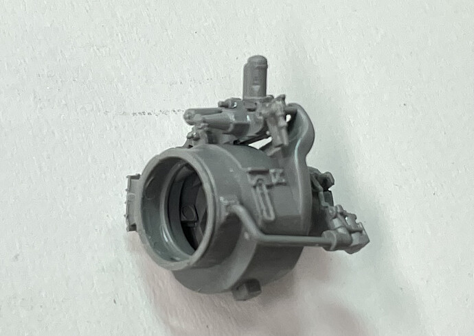
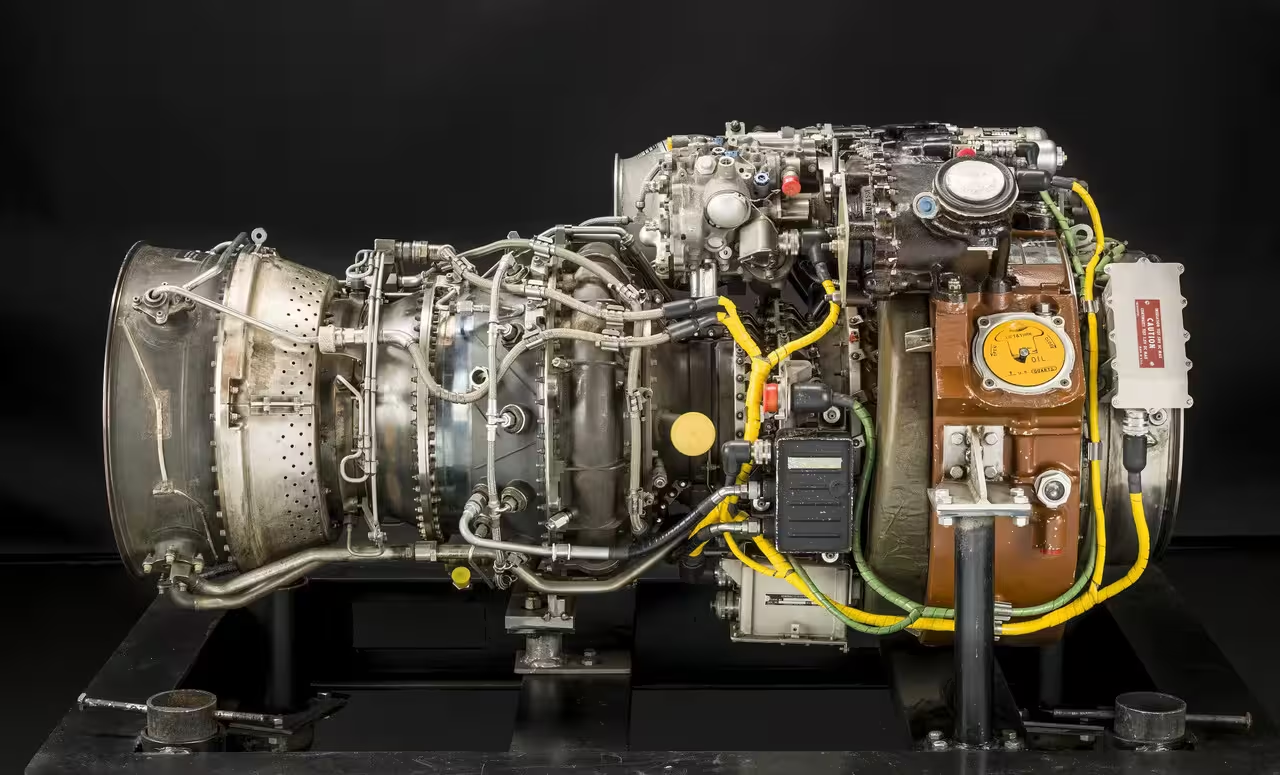
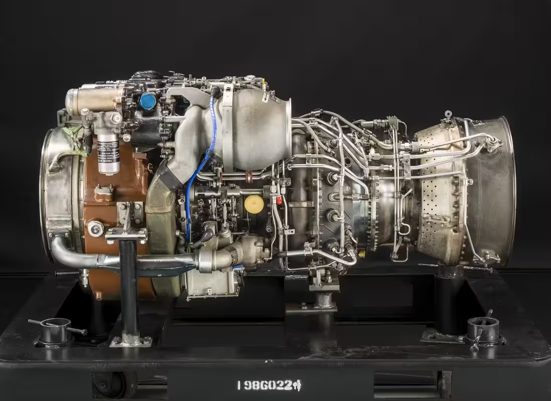
I put the fuze asside so all this would cure solid and got to work on the GE engines. This kit suffers from part over-indulgence. There are parts with glue surfaces that are much less than 1mm sq. They are so fragile and untrusty worthy that Iā€™m considering closing both engine bays and not worrying about it. For the Seahawk I used the ResKit engine and now I know why. Doing all the doodads in styrene is folly.

The first horror was this pipe array that HANGs on the side. One end glued into the engine proper, the valve body glues to a tiny appendage hanging from a pipe array that glues into two spots on the engine.

That hanging joint came apart three times.

Making matters worse is another pipe thatā€™s supposed to tie into the top of the valve body and glue to another pipe thatā€™s just hanging out there. Then came the accessory drive. Instead of molding all the various bits to the one side of the two-piece body, they made them all separate pieces. I lost one. And thereā€™s an oil-filter looking thing thatā€™s even attached in a more precarious way (if thatā€™s even possible). This piece fell off three times. I used Tamiya Cement. Then Bondic and then CA. None of it worked. Bondic, doesnā€™t always adhere too well to styrene, and didnā€™t in this case.

Iā€™ve thought about replacing all the piping with metal and/or reinforcing these tiny joints with wire. Trouble is that the joint are so tiny that even drilling with a 0.010" drill weakens them further causing more breakage. The kit is over-engineered to drive up parts count. While it impresses, it doesnā€™t make for a satisfying build.

6 Likes

Youā€™re not selling the takom kit at all. :grinning:
Iā€™m glad to watch you build this difficult kit (to my eyes).

3 Likes

I tell it like it is. With 70 years of modeling experience, I think Iā€™m eminently qualified to determine what does or doesnā€™t make sense.

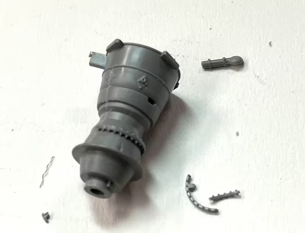
I persisted with the engines and have had marginal success and will have at least one bay open. I also changed the assembly routine to more closely follow the instructions. It was easier to glue all the apparatus to the accessory drive when it was off the model than attached. This is also true for the grit separator. I tried to glue the separator drum onto the dirve without the manifold. With the second engine I glued the manifold to the separator and then will install this as an assembly. This provides two points of glue contact at each end and supports it while drying.

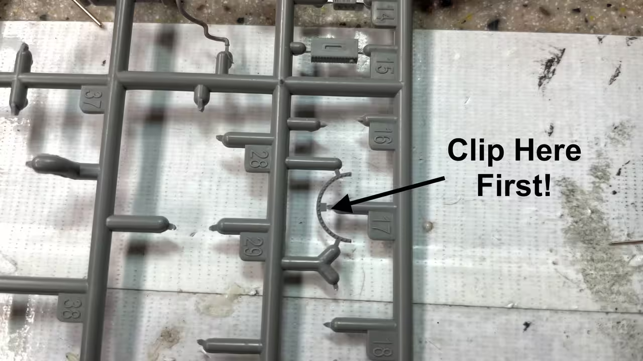
The compressor section has simulated bolt circles that are glued in in half-circle segments. One broke in cutting from sprue.

It complicated the gluing task, but I got it on. I also figured out the cutting sequence so it didnā€™t happen again.

Cut the center lug first, then cut the ends. The removes the stress point and lets the ends flex under the flush cutter.

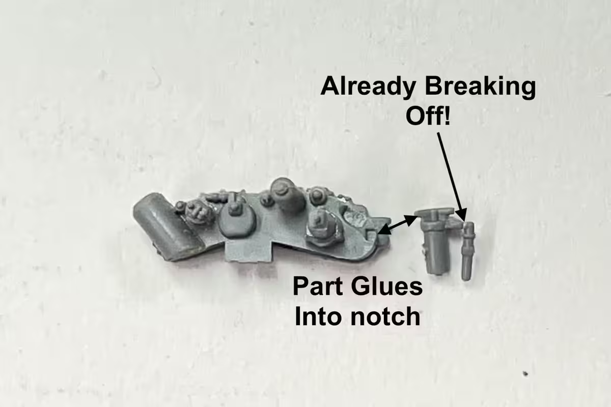
I lost another tiny piece for the accessory drive for engine #2. No one will notice, but it bugs me, that even with my parts catching drape attached to the work bench and clothes-pinned to my shirt, the darn things still get lost. Also, hereā€™s that part that has almost 0 glue surface. I donā€™t know what Takom is thinking. Itā€™s not even possible to wire this piece on. Just not enough part to drill. Iā€™m leaving it off. Also the little pipe extension on the part is already breaking off and I have done anything to it yet.

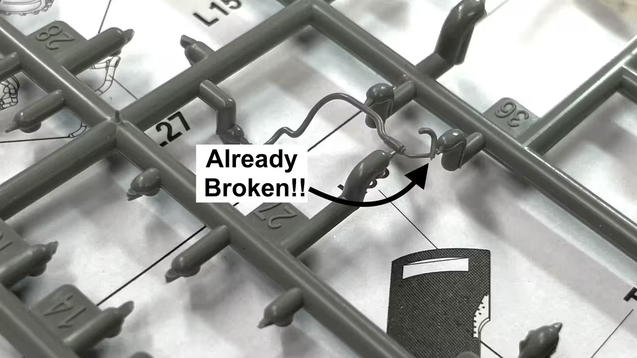
Speaking of breaking offā€¦ One of the styrene pipes already had an end broken in the sprue leading me to use .5mm solder without giving it a second thought.

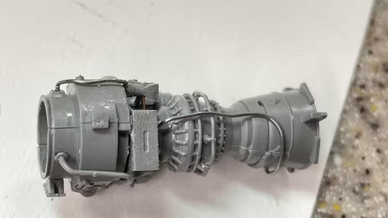
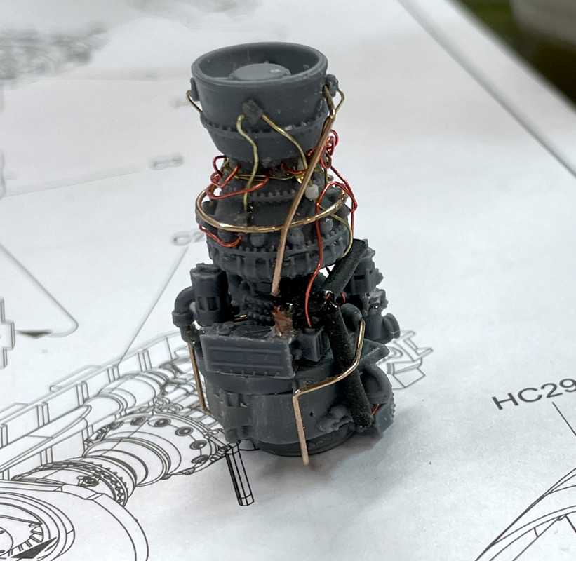
Hereā€™s the first engine mostly complete. I have to decide when to pipe it some more.

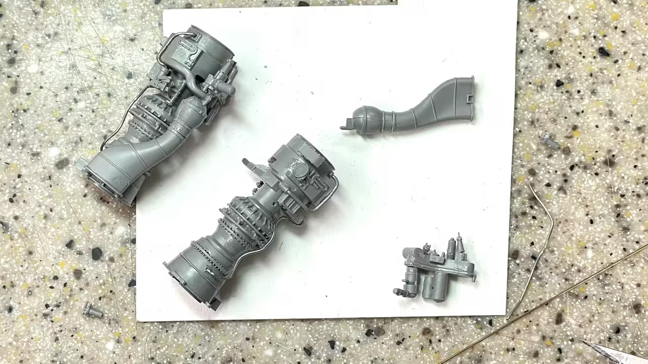
Hereā€™s the second engine ready for final assembly.

Thereā€™s a lot of piping that can be added. These images also show the major color variations on the various sections of the powerplant.

I did add all this to the Seahawk engine and almost went blind in the process.

On another frontā€¦ my next major naval project is an attempt to make a 1:48 model of the Battleship New Jerseyā€™s #3 Engine Room. Ryan Syzmanski is excited by the thougt of having this on the ship, as am I. The main problem was the lack of detailed drawings for all the machinery and the roomā€™s layout.

I did some research and found it. There are original drawings of exactly what Iā€™m looking for at the National Archives. The only problem is they are not digitized. I will have to view them in person. They are at the National Archive repository in College Park, MD. I need a National Archive Researcher Card, which Iā€™ve applied for.

I will be able to copy and photograph the drawings. There are 160 of them in the set in which Iā€™m interested, so it will take some time to find what I need. Iā€™m excited by this as it seems the chase will be as much fun as the capture. I know I can draw and produce what i need to create the model. The challenge was finding information about it. That seems to have an answer. I will be posting this all in a separate thread when the time comes.

10 Likes

Work continued this afternoon.

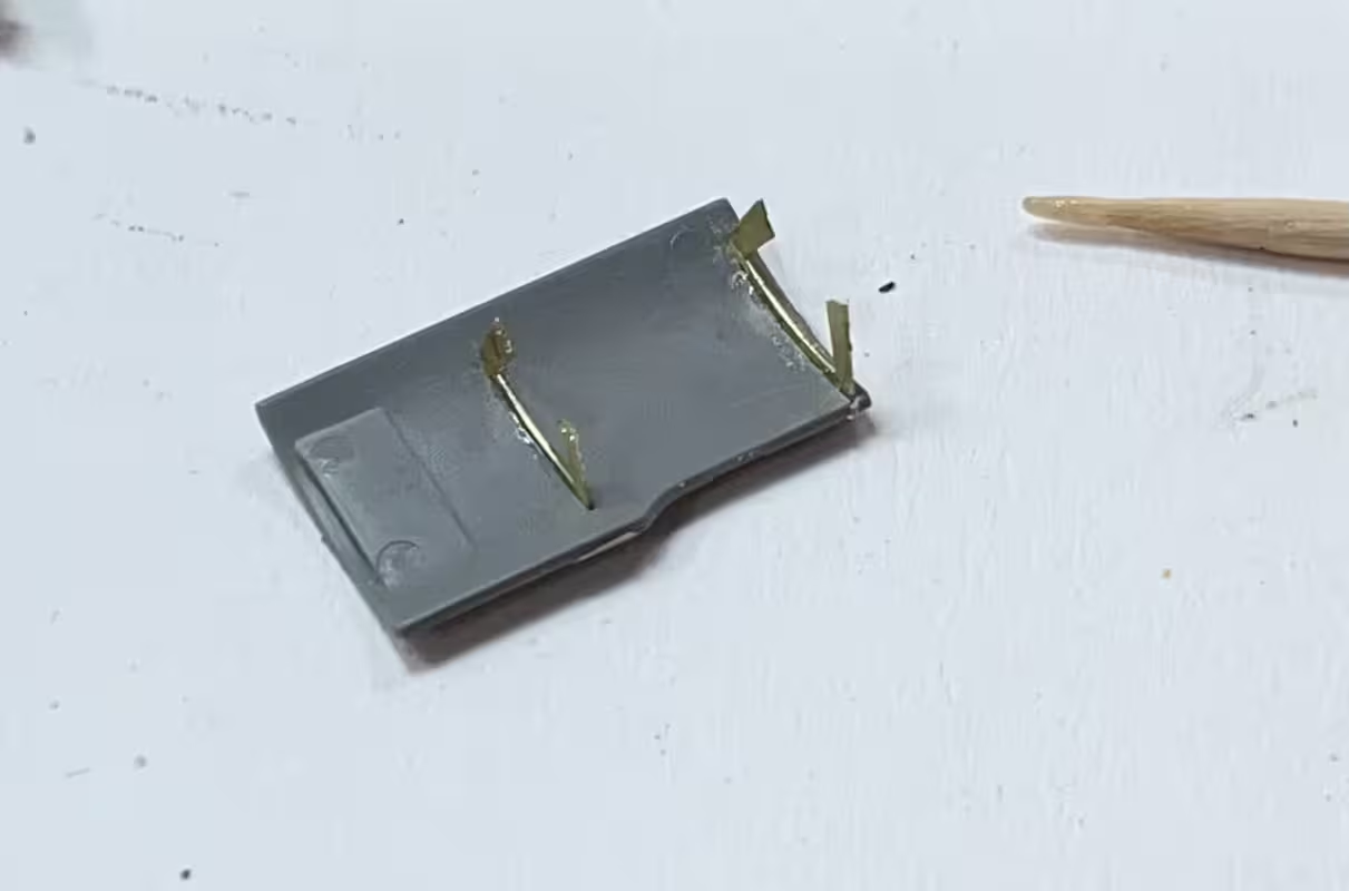
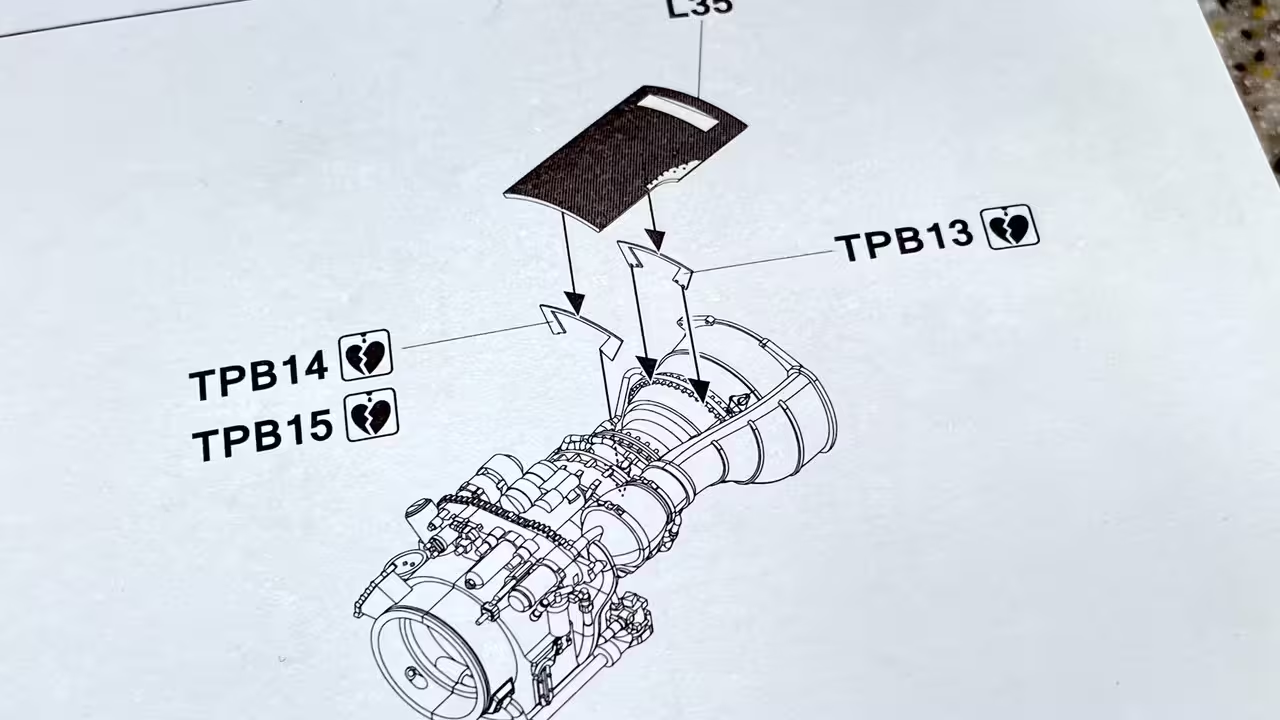
Finished up engine #2 and prepared the heat shield PE brackets. There were fine slots to accept these little parts which aided in getting them situated. I initially used the J-B cement again, and stabilized the joint with some thin CA. It will dry by Monday when Iā€™m back in the shop again. That said, the zero (or near zero) area at the other end that supposed to hold these panels over the engine is worrysome. I donā€™t like these kinds of joints. They make for very fragile assemblies and this modelā€™s going to have to take a trip. I may add some styrene bits on the engine to give more gluing surface to make it more secure.

Hereā€™s how that part goes onto the model. I think youā€™ll agree that itā€™s dubious at best. Just because you can make something close to scale thickness with PE, doesnā€™t mean you should. You wonā€™t see these brackets and they could be styrene and much thicker. The diagram doesnā€™t really show exactly how this part is supposed to fit. It does look like the case bolts engage in the four holes in the rear bracket.

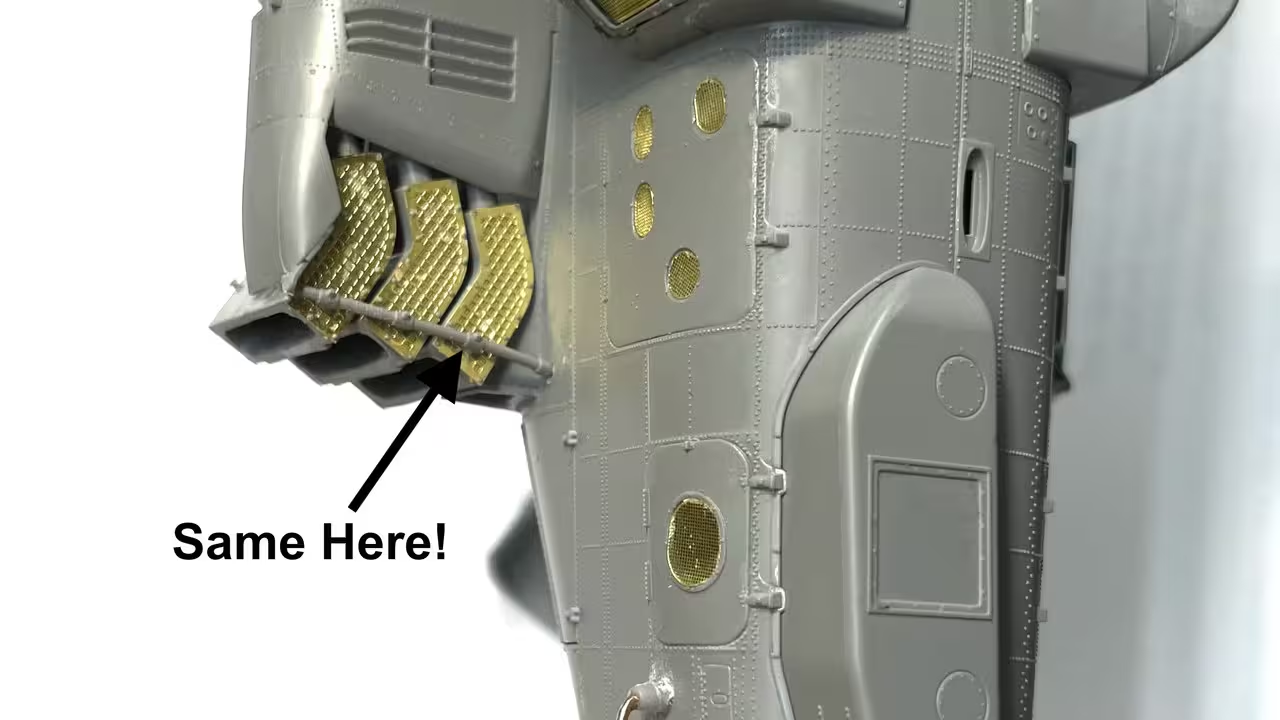
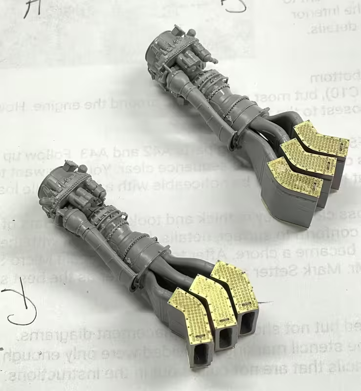
While this was drying got started on the exterior exhaust system. Unlike the Seahawk which has a straight out tailpipe, the Apache has an elaborate ā€œexhaust coolingā€ arrangement that mixes cold ambient air with the hot exhaust stream to mitigate the threat of heat-seeking missiles. The exhaust splits into three chambers, each with top and bottom inlet screens to bring in the outside air where it blends with the hot exhaust stream.

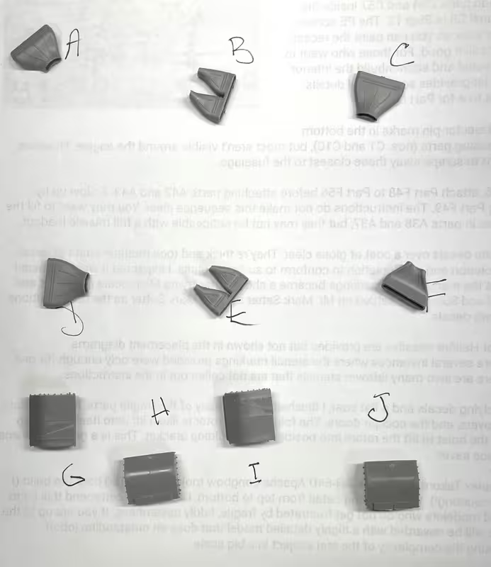
There are six units and they are different. The instructions label the manifolds rom A to F, and the mixing boxes from G to J. I made a chart to keep them in order.

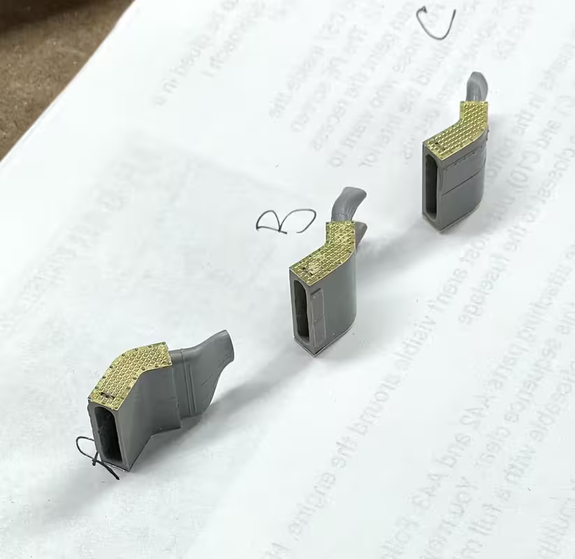
Thereā€™s a PE part simulating the inlet grills that I glued on with gel CA and then applied accelerator on the top of the screen to cure the stuff quickly.

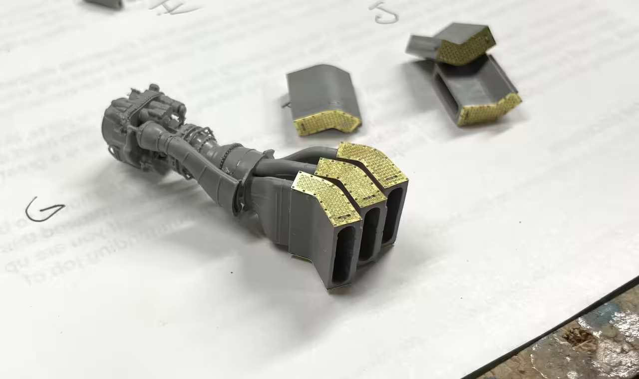
I assembled the first set to the engine outlet. I sat and thought a while about the painting sequence, i.e., paint before exhaust or after. I settled on painting after. The decision was based on getting a very solid glue joint on this fragile assembly and that would be without paint.

Quitting time was approching (it was cocktails Friday night), but I wanted both sets assembled so they would be perfectly cured for next session.

The next steps include putting on the skin around the engine. Painting and further engine detailing (if I decide to do more) needs to be done before then. From photos, it looks like the manifolds are natural metal, probably stainless or titanium. The grills are black as is the exhaust outlet from the mixing boxes. Itā€™s amazing that this power pack, weighing a bit over 500 pounds puts out over 2,000 hp. Gas Turbines are very efficient.

7 Likes

Sporadic work sesssions before the 4th. I did get to test fit the engines into their housings and continued building up the engine shrouds. I have to paint things before going further.

The instructions donā€™t tell you if itā€™s better to glue these two parts together before or after attaching them to the shroud base. Because of the critical nature of the fit, being a long edge with no tabs/pins, I chose to glue them now. Glad I did as itā€™s much easier to fit them on the shroud base when theyā€™re together. The joint is basically invisible.
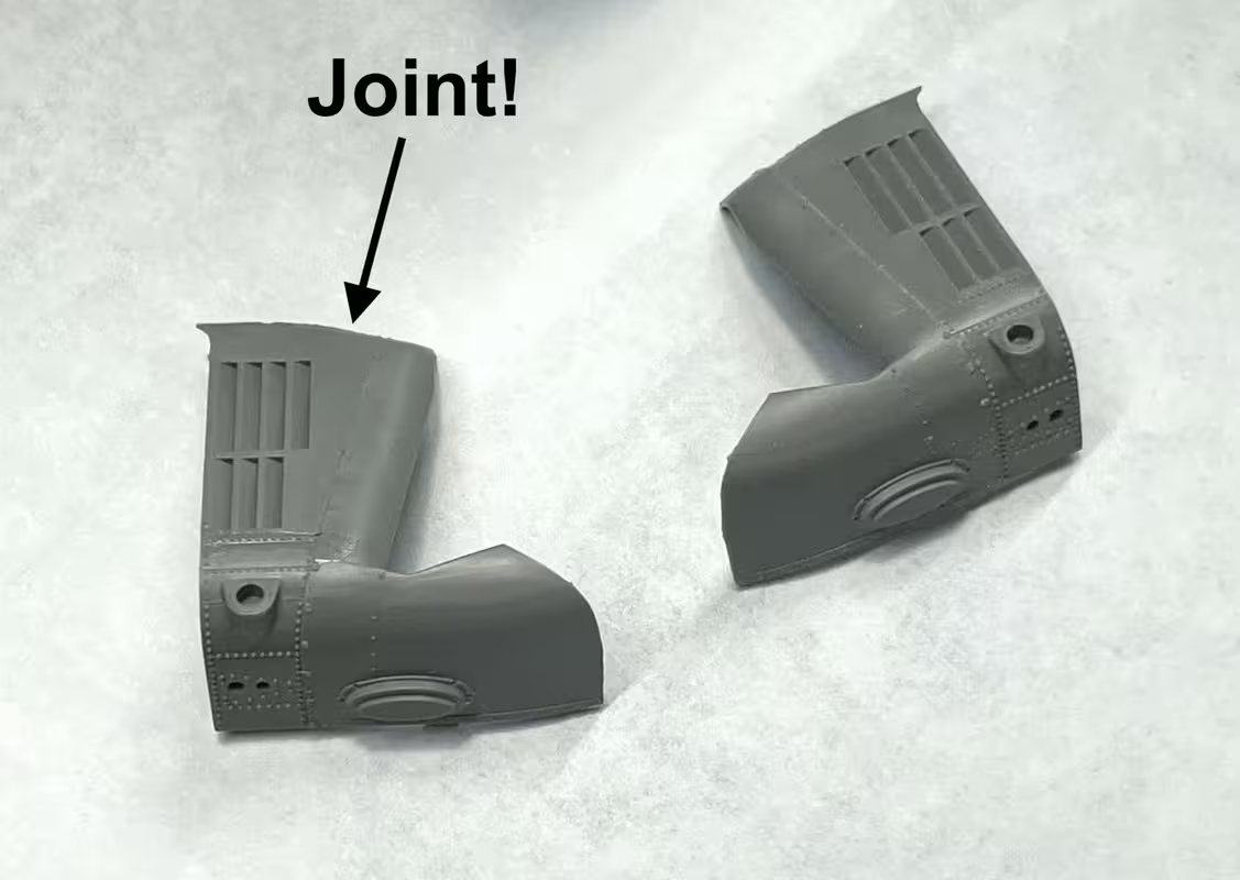
I also glued the opening portion of the shroud that serves as a work platform. It was a challenging joint with very little surface area. I let them dry for days and theyā€™re nice and secure. The prototype photos shows aluminum-faced batting in the square spaces n the door that is probably heat insulation. Iā€™m going to simulate that with Bare Metal Foil (after painting zinc-chromate green on all the rest of the insides.) Thereā€™s another frail ā€œtelescopingā€ support pole that connects these two parts. I may make it out of metal since it looks very prone to breakage.
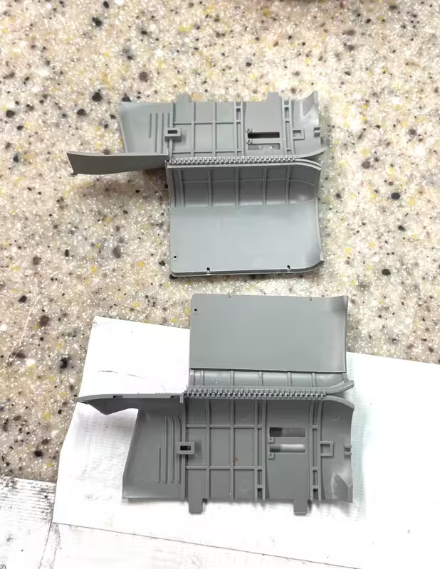
I test fit the shrouds (before gluing the doors) to the fuze. They needed a little relieving on their rectangular pins to they werenā€™t a press fit. Press fits are bad when youā€™re gluing delicate assemblies.

The engines engage the slots at the bottom. Before they go in, besides paint, there are a couple of unseen details that go in under the engines. Shrounds are not glued in.
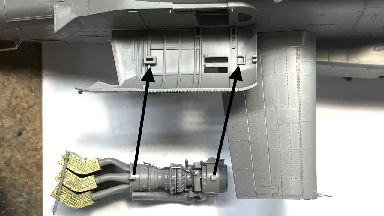
There are also two, frail plastic bars that tie the exhaust coolers together, one on top and one on the bottom. The gluing surface to the tiny bit of styrene thatā€™s sticking up was way too small for a good joint. Before gluing I had to pull the three manifolds together and CA them so they were touching. Otherwise, the bars would not align to their pins. I then used Tamiya cement and followed up with med CA. The long one, engages in a hole in the fuze. The short one looks like its end glues to the upper shroud assembly.
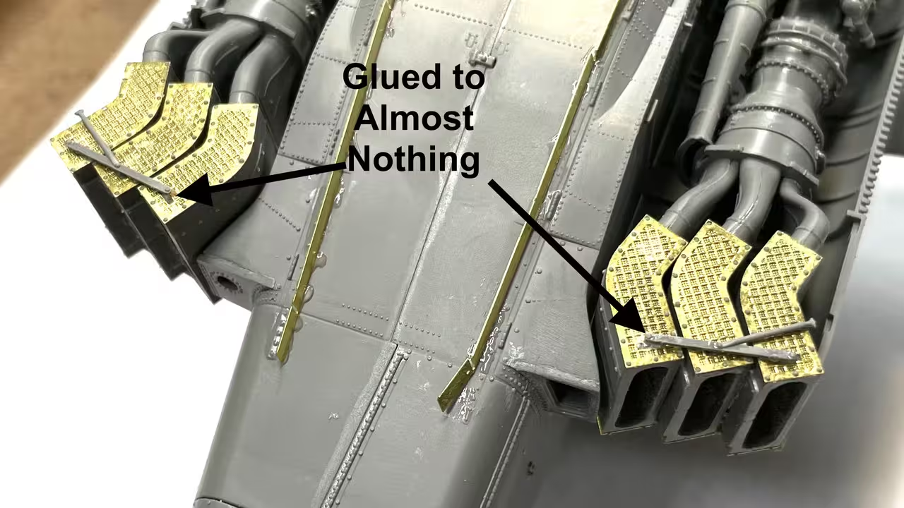
You can see where this bar engages the fuze. Nothing gluedā€¦ all test fit.

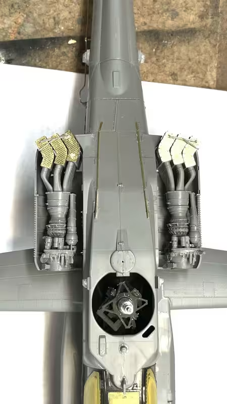
With both engines fit it looks very busy.
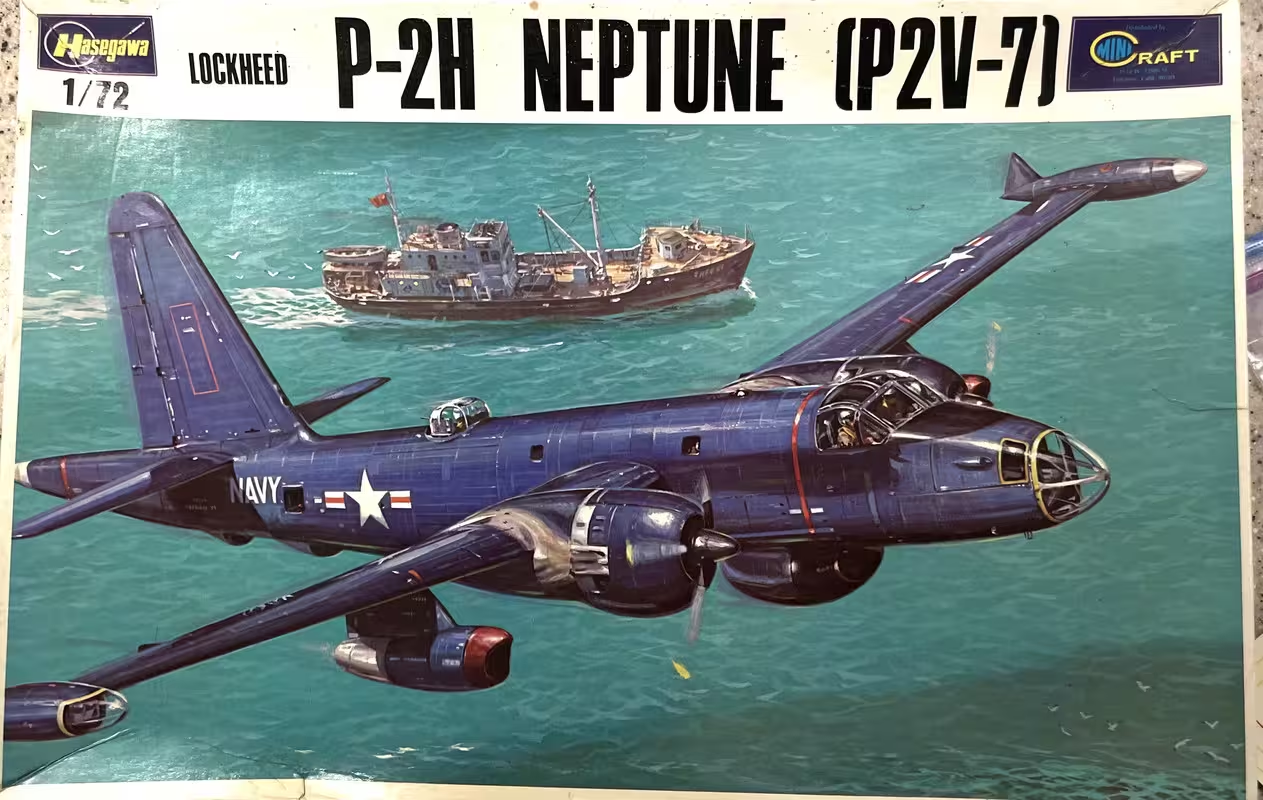
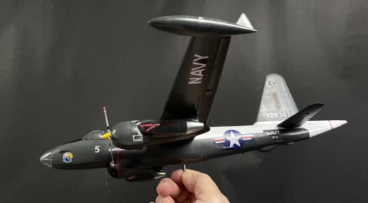
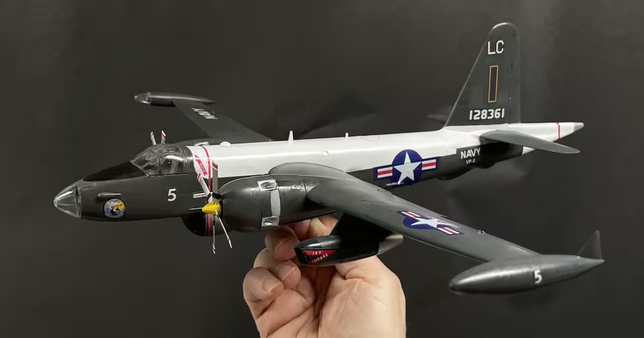
I have another ā€œcommissionā€ project for my wifeā€™s cousin. Found out recently that he was a flight chief on a P2V-5 Lockheed Neptune during the Cold War. I found a Hasegawa kit on eBay and will build it to his planeā€™s id.

Decals were very, very old and yellow so all need to be redrawn and reprinted. Not being able to print white, and using white-background decal paper, means that white lettering either has to be individually hand cut and placed, or I have to match the glossy sea blue background and have the lettering connected with the background color. Iā€™ve done this before with decent success. it just takes a lot of fiddling with colors on CorelDraw to get a match with inkjet ink. I make color swatch sheets to do it. Last time it took 14 test colors to get it close. If I use Vallejo Gloss Sea Blue, I already have a match for that color. I donā€™t like Vallejo since it takes so long to dry. Iā€™m thinking about using Mission Models colors. Not sure Iā€™m going to post this model.

Here are two pictures of his actual plane. His plane was the one that tested the nuclear depth charge in the early 60s. Historic!
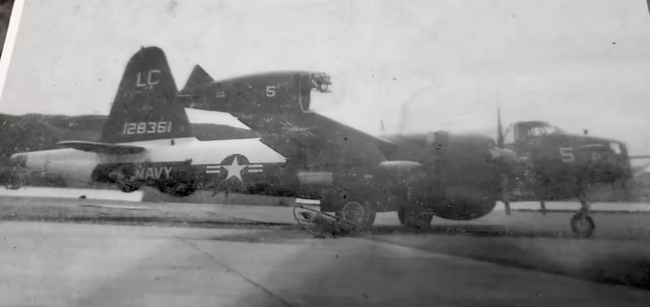
It DID NOT have the top gun turret.
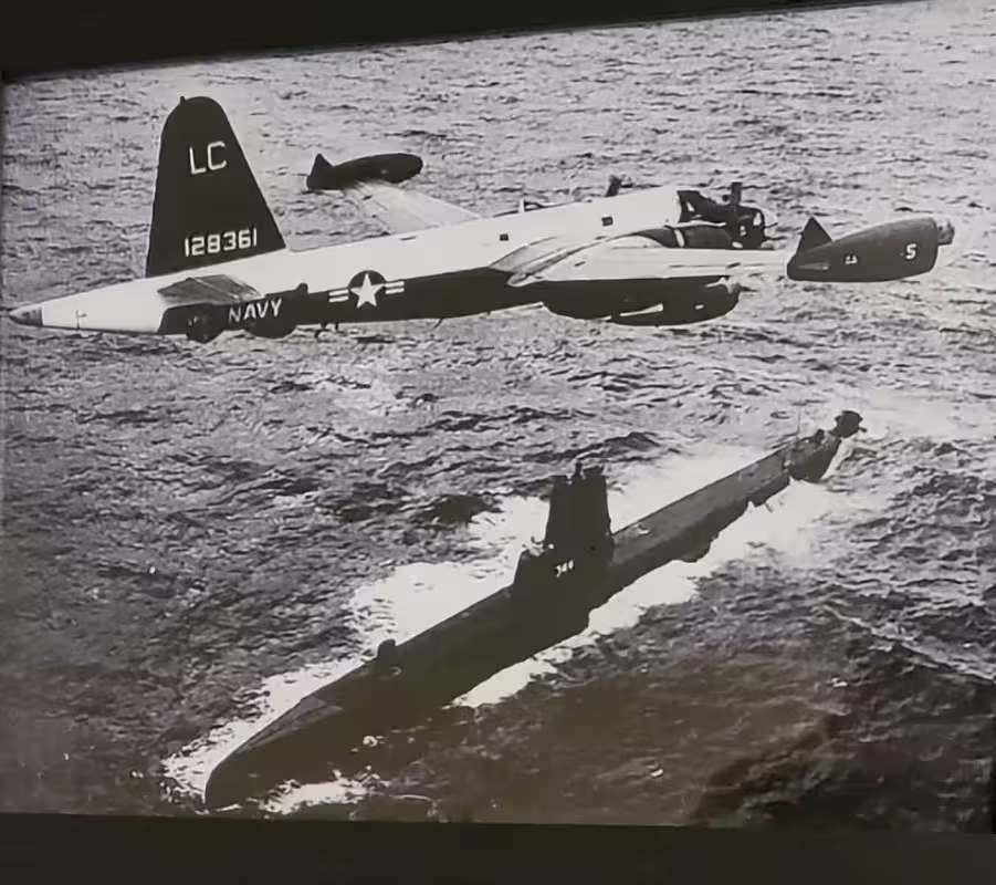
The Neptune was one of the first Piston/jet craft made along with the B-36. The piston engines were the amazing Wright R-3350-30W. These were the final evolution of radial engines with turbo-compounding. Instead of using exhaust to drive a supercharger (turbocharging, the three turbines were geared directly to the crankshaft through a fluid coupling. They created an additional 500 horsepower. Thereā€™s a cutaway version of this engine at the Franklin Institute in Philadelphia that really impressed me as a kid. I had no idea how special that arrangement was. The three exhaust stacks spaced around the nacelle equally (180Āŗ) is one of the ways to identify this engine. The engine produced 3,700 hp with the same fuel consumption as the ubiquitous R2800.
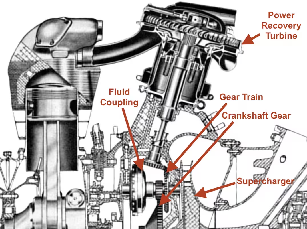
This engine was also found in the Lockheed Constellation, the DC 7, and the Globemaster 1 cargo plane. The B-29s had the 3350s (along with the A1 Skyraider) but they werenā€™t the turbo-compound model. 3350s were also one of the first engines to have direct injection into the combustion chambers to rectify the fuel imbalance problems. Thereā€™s a nice docuementary on this engine. It was a monster to perfect an there were 8,000 engineering changes before it finally proved itself. And it did! They make over 8,000 of them.

Being a flight engineer on these piston/jet planes must have been wild. They used the jets for take off, and had shutters that closed them off during cruise so they wouldnā€™t windmill.

Okayā€¦ enough digression. Every one who celebrates have a safe and happy 4th of July Holiday.
5 Likes

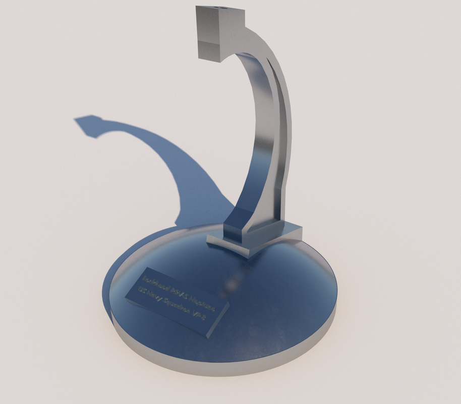
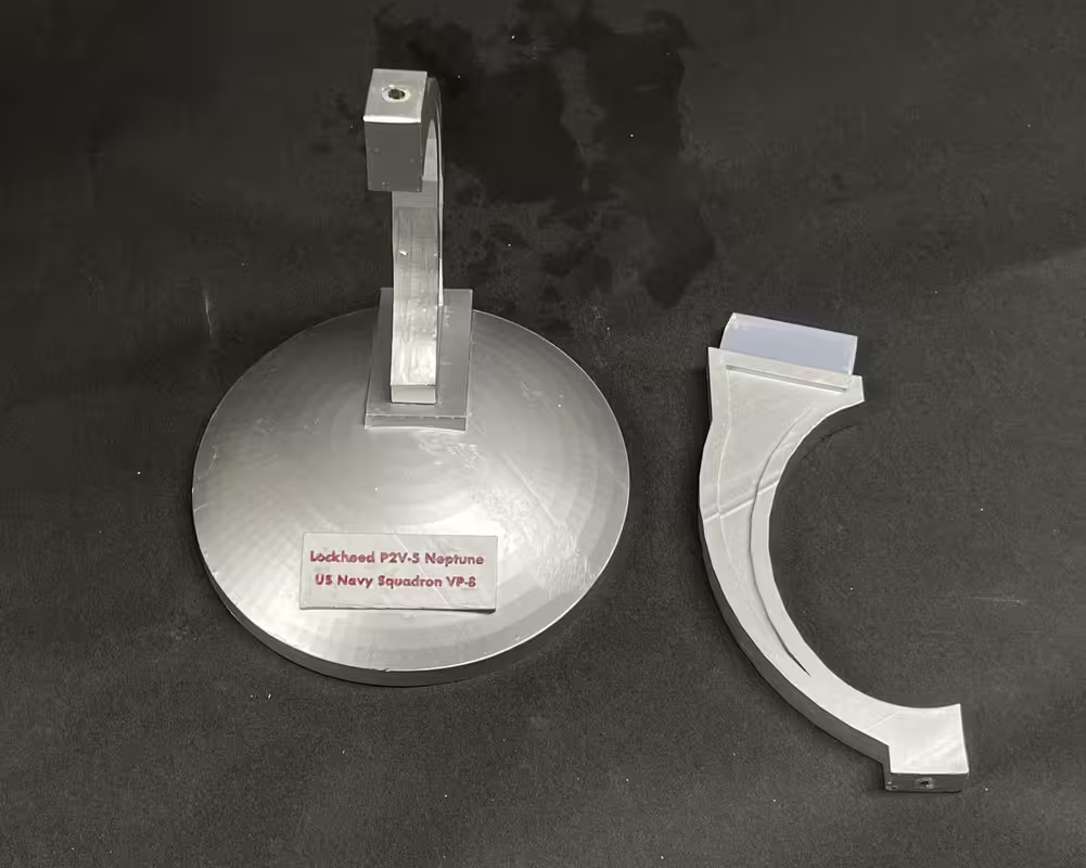
After the P2V fell when I was preparing to make a tail prop, it destroyed the main gear. I now had to figure a way to close the gear doors. There actually was no provision for this eventuality. And then I had to desgin, draw and 3D print a stand. I prepared the model with a brass shaft that penetrated the fuselage up to the top. I expoxied this into position with a J-B Epoxy formulated for plastic. I drilled the brass to accept a piece of 5/32" drill rod. I made brass sleeves that I inserted into the stand supports to accept this pin. I delivered the model to Larry two weeks ago during a trip to philly. It was also in this trip that I deleivered the 5" secondary battery model to the New Jersey. Larry loved the model since it replicated his specific plane and squadron.

I made a simple two-part stand and am providing him with 2 choices showing the plane in different attitudes. I painted the stand today and will ship it out tomorrow.

For a simple model, and a short build time, it was certainly challenging right to the bitter end.

Hereā€™s a rendering of the stand directly out of SketchUp.

And hereā€™s the painted stand ready to ship.

And that folks is the end of that.

4 Likes

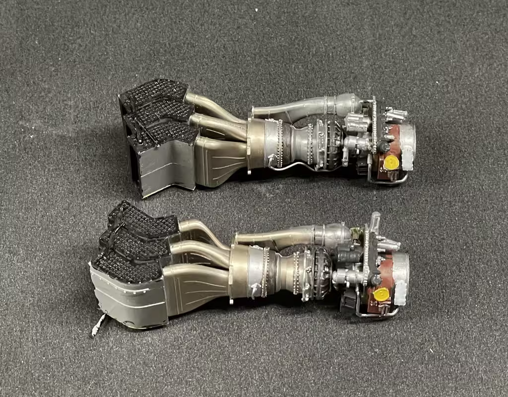
With the P2V Neptune and the 5" Secondary Battery delivered, itā€™s back to the Apache. I painted the engines today. I also have a new Elegoo Saturn 4 Ultra. This printer is light years beyond my first generation Elegoo Mars, just five years ago. It even has an AI camera that records the print. I no longer have to run down to the workshop to check on progress. It can even do a times lapse photo series. Itā€™s 60% larger than my Mars 3 and 40% faster. Itā€™s 6 times faster than my Mars Classic.

I chose not to fully pipe the engines, but did enough to make it a little more complex.

I will be increasing my work on this model over the next few weeks. In October, Iā€™ll be going to the National Archives to review the Battelship New Jersey engineering drawings to gather detailed information about the engine room project.

7 Likes

Well dear followers, I finally am getting back to work on the Apache. I had several things that took priority including things all of you responded like the 5" turret, the book on 3D printing and the Neptune. Now Iā€™m back, and Iā€™m not really happy. The kit is ā€œOver-partedā€. While I like a lot of parts, some of those with this kits are a} to small to mess with, and b} are in places where theyā€™re not seen, or are so fragile that thereā€™s no way to put it together via the instructions. Case in point all the antennas and things sticking out of the bottom. Iā€™m leaving all of that, plus all the hand grabs until almost the end since I will surely break most of them off during construction.

I got both engines and all their housing installed. Prior to installation I painted the inner surfaces primer yellow which seems to be the color on the real bird. Thereā€™s a faux stainless steel heat shield that covers over the hot sections of the engines, but as happens when a model is put aside for an extended period, I only found one of them. Ergo, Iā€™m leaving them off. Those square spaces on the door are covered with insulating foil which Iā€™m going to attempt to do with Bare Metal adhesive foil. May not work.

The door hinge area is very fragile and one fell off during handling. I got it back on with CA, but it needed a better engineered attachment if they intended on having them open.

The wheels are 4-part assemblies. You have a choice of weight flattened or fully inflated tires. I chose weighted. I paint the hubs and tomorrow will do the tires. I also assembled the tail wheel, but didnā€™t do any paint yet.

Tail piece was next. Simple glue job, but important part since the tail plane actuator and rear landing gear mount to it.

I glued the tailplane together first, but it has to captivate two pins that represnet the tailplaneā€™s hinge point. The instructions sort of show that pieces going together over the pins, but itā€™s ambiguous (to me), so to get the tail on I had to spread the not-so-quite-dry glue joint, slip it over the pins and re-glue. Itā€™s okay and moves. Moving is not really important since the actuating mechanism is a solid piece. The tail wheel mount has many parts and seems very Fragile too. I worry about that. I may leave that off until the rest of the masking and painting is done. Just stripping masking tape can exert enough force to break delicate assemblies.

And of course, there are antennas as molded-on parts that are breaking off before I get out of the starting gate. I will probably replace with guitar strings to make it sturdier.

Iā€™m not the steadiest nor the most careful of model builders, and now that Iā€™m less than a year from being 80, no one expects me to be, so I think a kit like this is about my limit for hi-parts-count plastic kits. I admire guys that can get kits like this together without all the work-arounds that encounter.

More work will happen tomorrow.

6 Likes

I just had a mammoth catch up on this incredible build. Very impressive work which will be a go to reference for when I get round to building an Apache!

Very nice looking P-2 also.

I hope youā€™ll tackle the MENG version next.

Nope! Next up is Trumpeterā€™s large scale F-35B where Iā€™m going to build a second engine assembly for external display. I probably will attempt 3D print all or part of it. I also have a railraod structure to build and another massive Battleship New Jersey custom project, Engine Room #3. Iā€™m stalled on that one trying to get good working drawings on which to base the model.

Why Meng? Is it better than Takomā€™s?

No idea, but Iā€™ve never built a bad MENG kit.

This kit is going to make up into a gorgeous, but very delicate structures that are going to challenge me to get it successfully to my friend back in the Philly area. I got the wheels painted, the tail wheel gear built and installed and started working on the complicated and delicate tail rotor. I find the Apache interesting with the two sets of tail rotor blades being assymentrical to one another. Anyone have any comments on why they did this?

The bird needed to be upside down so I cobbled together a very quick (and dirty) foam stand that would protect the delicate main rotor head from damage.

Also shown in the above is the tail plane actuator that connects between the fin and the tail piece on the ship. The junction between the piston rod and the fin block was so thin and weak that it was half off during the sprue separation. I added a small ring of Bondic around it to reinforce it a bit. I then applied liquid cement to the finā€™s hinge area which strengthened it some more. Itā€™s still delicate.

The tail gear is a multi-part affair which some very fine ones that should be metal or 3D printed resin instead of styrene, but you use what youā€™re given.

Here are some subassemblies for the tail gear.

The wheel yoke had another very thin section that broke during assembly. Since itā€™s not made to rotate, I was able to glue it all togehter.

The gear assembled to the fuselage reasonably well, but one of those very fine-section rods was having trouble staying glued. Didnā€™t want to over-glue since it was so small it could simply melt away. I reinforced with some Bondic, but that cracked as I was manipulating it into position on the ship.

When I first glued the gear in, I forgot to install the shock strut. I tried installing it with the rest attached to the ship, but wasnā€™t going well. I pulled it off, added the strut and reinstalled on the ship. Allā€™s well that ends well. I really donā€™t understand what the fin-shaped appendage actually isā€¦ and ideas?

The first parts of the tail rotar are the hub and the actuating links that go into the tail housing. Theyā€™re litte as evidenced by the scale of the #11 blade.

ā€‹

You have to captivate the plunger and mount between the wings and then glue this to the rotor hub. The alignment pins are very small and it required very little cement to glue together.

ā€‹

I glued it to the ship and found that the angle of the yoke is not perpendicular so itā€™s best to glue this before the glue is fully hard on the subassembly. You also have to be able to move the links into alignmentā€¦ another reason to not have them glued solid before attaching to ship.

ā€‹Rotor work continues tomorrow.

7 Likes

I got the tail rotor assembled. Itā€™s a challenge. Very engineeredā€”to a fault. The hub assemble with the pitch rods is exceptionally unstable, although it got better when the blades went in a captivated the pitch rods.

I was met with a sprue problem where the feeders were either broken or not fully formed. This led to one of the shorter ones being badly bent and almost broken before I even got to it.

The pitch rods didnā€™t line up with the tiny pins on the blade arms. To glue them I clipped the pins so the misalignment didnā€™t affect gluing. Thatā€™s a really fine Swiss tweezers for scale.

The two sets of blades glued to the arm extensions on the hub. The tiny pins to which they align are assymetrical and it wonā€™t fit well if you get them reversed. I needed all my Opti-viorā€™s magnifying power to make sure I was attaching to the correct pins. The imagae points this out.

Iā€™m not puttint the blade assembly on until near the end.

I have a decision to make. Iā€™m not sure my friend has the display location to have the ship with the blades extended. However, the folded blade scheme means not installing the Long Bow antenna, which is such an iconic aspect of this Apache version. And thereā€™s the terrible fragibility of the blade support rack. I decided to attempt to build the rack. If it comes out okay, then Iā€™ll do the folded blade version. If itā€™s too frail to actually do the job, I will go with open blades and let my friend figure out where heā€™s going to put it.

These two pictures show just how invoved this rack it. And here I thought the Seahawkā€™s support rack was complex. The difference is the Seahawks blades are stowed all the time and are hudraulically actuated, whereas the Apacheā€™s are folded manually and only done when the ship is being air-lifted on a C-17 or its ilk. When folded the Long Bow antenna is removed and the extendable rotor shaft is retracted.

Assembly started with the parts that wrap around the fuselage. Thereā€™s a lot of little and excessive PE, but Iā€™m attempting to use it.

After adding the PE to the individual pieces I had to install these connecting post between the two sides. After fussing with them trying to make them stay still while fitting those tiny rods, I went to my old standby PanaVise to hold at least one part still. This worked okay. They have to cure overnight since itā€™s a very fragile assembly. Still dubious about its strength to hold the blades for the trip back East.

I got the group done and will be ready for the next steps tomorrow. With these assemblies I have to overcome my desire to keep moving and let them really dry. Otherwise, Iā€™m repairing more than building.

Here are the two sets. My method of holding PE is to use gel CA which can be applied in very tiny quantities and it stays put and does not cure. Then after the PE is in place I just get the accelerator near the joint to cure it. For the tiniest part I put the CA on the plastic and dipped the part (held in a tweezers) in the accelerator. It cures almost as soon as I get the part in place. No room for adjustment in the latter method.

Until next timeā€¦

4 Likes

Finished building the blade rack. Itā€™s very, very fragile and Iā€™m still not sure if itā€™s the best way to proceed. Iā€™ll paint it as if Iā€™m going to use it, but it does change the rotor hub and that decision needs to be made shortly. The blade crane glues to the rotor hub without the Long Bow radar.

First up was the frail diagonal braces. Before removal I was met with one of the ends bent in such a way that any more bending would break it off. I wish Takom would have fudged it a bit and left the diameters constant up to the end link. By narrowing it to make it ā€œmore scaleā€ left it very weak and prone to breakage.

AH-64D Blade Support Truss Rods.jpg

The instructions had you gluing these on BEFORE assembling the main part to the base piece. That would be folly. Their gluing surface is micrscopic and if they were dangling there glued only on one end, it would not have ended well. Instead I glued the main parts together and then put on the diagonals. Even then, when assembling the lower part, they were coming unglued multiple times.

AH-64D Blade Support Subs.jpg

The base supports went on, but I think theyā€™re on backwards. I donā€™t believe they are symetrical since the trial fit on the fuselage seems to fit better facing one way than the other.

AH-64D Blade Support Rack Comp.jpg

The support wings went on next. These are even more dubious than the rest of the assembly. Theyā€™re held by as tiny plastic shaft simulating a hinge. I reinforced with Bondic, but have not illusions that itā€™s going to last. I tried the assembly on the model and donā€™t like that itā€™s tipping back so much. When I reversed as noted before, it fit better telling me that the base arms are not the same and I them reversed. Too late to fix. The parts would break in attempting to rectify. The blade holders on the arms are pinned with 0.032" phos-bronze since their mounting lugs were almost not existent.

AH-64D Blade Support Test.jpg

Lastly, they have you assembling a blade crane which is used to swing and supprt the blades when getting them into the holders. This is like the rest, being very scale and very fragile. I had the side arm reversed, but caught it in time to break the almost-set glue joint and put on properly. Take a look at that tiny glue spot thatā€™s going to hold the crane blade shoes in place hanging on the end of the arm. I was attempting to glue it on yesterday, but decided to let everything cure overnight so I have a fighting chance to get it together. And then I have transport thisā€¦ hmmmā€¦

AH-64D Blade Support Crane.jpg

Not sure what color to paint this. For the Seahawk, all the blade stowage hardware was red. I will do some research to see what color this stuff is for an Army bird. Todayā€™s session will be building the main rotor hub.

Wellā€¦I guess I got my answer. Almost all red, but some white and black details as well.

It would appear that thereā€™s some soft material between the rigā€™s legs and the fuselage. Notice also that the support angles are natural aluminum. All the bolt heads are natural metal also. Fun with the Molotow Chrome pen

More trivia: the blade stowage rig cost $160k and weighs over 1,000 pounds. All the shoes slide on their respecive beams. The support legs are held to the fuselage by straps that wrap underneath. I may try and simulate those. Notice too, how little weathered the Appache is. In the film from which I pulled these screen prints, there was a C-17 that is holding the Apache and it was immaculate! People over-weather too many models, especially modern equipment thatā€™s not in active combat.

7 Likes

Yesterdayā€™s session had a turning point. I checked with my friend if he could handle the extended blade version and he said he could. Therefore; the work done on the support rig was for naught. As it is, before talking to him, I finished it up. Starting with putting the crane shoes on. A tiny glue area is holding the stem and it would break in a heartbeat.

With the good reference photos, I painted the rig and then set it aside never to be used again.

missing is the little bit of silver on the PE brackets.

The reason I needed the answer now was due to different parts having to be used in the rotor hub for the folded wing mode, and this was the point those parts were going to be used.

The rotor hub arms are another very finicky construction with microscopic plastic parts that donā€™t like being captivated by tweezers. On one sprue all of these parts were unconnected from the sprue on one side, just waiting to be lost. I didnā€™t lose any then, but did lose 2 out of 8 further into construction. This is how big they werenā€™t.

Just the act of attempting to remove any sprue debris risked the loss of the part.

These parts made up the arm sub-assemblies.

I glued all four subs together and then discovered that they had to captivate this pin on the flanks of the top hub piece. Luckily, the glue hadnā€™t hardened totally and I was able to pry them apart, get them all connected, add more glue and put them back together. Frankly, with having to trap the side arms into their little pockets AND get the pin in place seemed too much to do at the same time anyway. I donā€™t know why Takom thinks it was necessary to make that joint movable. I know itā€™s movable on the 1:1 model since this is the pitch axis of the blade, but it could have been a keyed pin that could have been glued AFTER building the arm, and assembly would have been a whole lot less stressful.

Once again, itā€™s details without a purpose. The diagram shows the relationship. Itā€™s one of the drawbacks of having instructions with no dialog. It would have been nice if there was a clear note to NOT ASSEMBLE ARMS BEFORE ATTACHING TO PIN! I also understand that these kits are designed for a global market and words would be a problem.

All the arms are in place.

So the glue would dry with the arms tight I clamped them all and let them sit overnight.

Thatā€™s where work ended yesterday. Todayā€™s a triple whammy day: Itā€™s Saturday so I donā€™t work in the shop. Itā€™s the Jewish Sabbath which should also prevent me from working and itā€™s Yom Kippur, and I definitely should not be working. In fact, I shouldnā€™t even be writing this post, but I will probably be forgiven. If you observe, have a good fast and day of Atonement! If you donā€™t observe, itā€™s not a bad idea to ask for forgiveness too. The list of sins on Yom Kippur for which we ask forgiveness includes just about everything so no one escapes unscathed.

5 Likes

Model building should not be considered work. I found that out the hard way.
If itā€™s a righteous build. God will forgive you.

2 Likes

From your mouth to godā€™s ears! Ahā€¦ but who determines the righteousness of the build?

My wife always reminds me that itā€™s my hobby and I shouldnā€™t complain about anything. Work is when someone else is telling you to do it and you answer to them. No oneā€™s telling me what do when Iā€™m in the shop, ergo, it ainā€™t work. (but when dealing with difficult kits, it sure feels like work!)

2 Likes

What youā€™re seeing today is about 2 hours and 15 minutes of work. It should have taken 1/4 of that time. But, as things go most of the time was searching for parts that left this dimension, scratch-building parts to replace them and cobbling together a mess that kept trying to disassemble itself. That said, it did get togther and when painted and detailed it will be reasonablly acceptable.

I did start with some positive stuff. I solved one problem: how to get the model to Bucks County, PA without breakage. Answer: keep the blades off and mount them at my friendā€™s house. To do this, I made some easily removable pins that can be inserted with a long-nosed pliers. I may also keep the tail rotor off for the same reason, but in that case, the shaft is very fragile, so having it exposed may solve one problem, but create another.

This isnā€™t prototypical but it will do the job. When painted, theyā€™ll look ā€œimportant.ā€

There were 4 small pillow blocks that went onto the hub piece. The instructions showed them going in with all the arms, but I read that you need to put the spool pieces in first and then the blocks. One got lost. I cobbled a poor repressentation out of styrene. Theyā€™re on the bottom and invisible, but they do support another link system.

Later in the build I dropped a swash-plate link and when finding it on the floor, found the missing pillow block. I removed my scratch-built version and put on the correct one. The links are very tiny, fragile and breakable. I lost one to the dimension rift. Seriously. It was in the middle of the work surface. I picked it up with my fingers and when I looked it wasnā€™t there. IT WASNā€™T ANYWHERE! There is only one explanationā€¦ dimensional rift. If all goes to plan, tomorrow it will be sitting on the bench right where it was supposed to be today. So I lost one link and then the other broke. I made two out of 0.032" phos-bronze. It doesnā€™t have the adjustment rings, but they work.

To make things like this I flatten the ends using a very old Vise Grip Model 10R. I keep tightening it down and crushing it until I get the thickness and width I want. I prick-punched the ends before drilling then opened the hole to a ā€œCā€ shape using a diamond-coated half-round file duplicating the model part. They have about a 45Āŗ twist on them.

I held them in place with thin CA.

But in handling them, a lot of the previous work decided to re-kit itself.

At long last all the pieces were back in place. I reinforced the diagonal link with Bondic, since the glue surface left something to be desired.

Last thing I did was try it on the bird. It will work out. But boy, these high-detail choppers have a lot of temperamental tiny parts. Iā€™m not sure if itā€™s a blessing or curse. I suppose there are modelers out there that donā€™t suffer these ills. Perhaps theyā€™re younger and a bit more steady, but some of the problems are simply kit engineeringā€¦ attempting to increase parts count and fidelity by make multiple part assemblies that could be done differently. Example: the control box for the Long Bow antenna is a rectangular with a core and 6 separate faces that have to be glued on plus some PE. Do you really need to have each face as an indivifual part? And some of the pieces would be best in investment cast brass instead of very thin cross-section styrene. Takom styrene is brittle. I had to do the same thing with the Kitty Hawk 1/32 Seahawk. All the those links had to be created in phos-bronze wire also.

Next up is the Long Bow system and the weapons and weā€™re ready for paint and decals. A lot of the Apaches are very faded olive drab. Have to think about itā€¦ The end is nigh!

6 Likes

I built the Long Bow antena system today. I scrapped the plastic wiring and substituted .5mm solder wire. I intended on using the plastic ones, but one broke so quickly that I stopped messing with them and went to wire. The control box had way too many parts. in addition to these shown here, there ware also two PE plates that made up the front and back. The back one was only there to add a tiny flange sticking out the side, and it will not be noticedā€¦. Period.

I had to open up some holes for the solder and, of course, broke a pasal of carbide mini-drills. Holes are way too expensive!

A long time ago I broke the plastic vertical shaft and made a brass sleeve to connect the broken parts. As it works out, the sleeve itself works to center the antenna. I tried the antenna on the ship and it works okay.

Hereā€™s that sleeve. I opened up the bottom hole in the antenna to accept the 1/8" sleeve.

I have good references on the painting of the Long Bow System.

Last thing I did today was start on the foil application on the engine doors. This all needs to be done before I mask it up for the exterior painting. Iā€™'m using Bare Metal Foil bright chrome. I measure the spacing with dividers and cut the foil with a brand new #11 blade. Iā€™m also going to add textured ChartPak tape to simulate the anti-slip stripes on the doors.

Onward and upward.

6 Likes