Takom Iowa Class Mark 7, 16"50Cal Turret with Full Interior Start-to-Finish

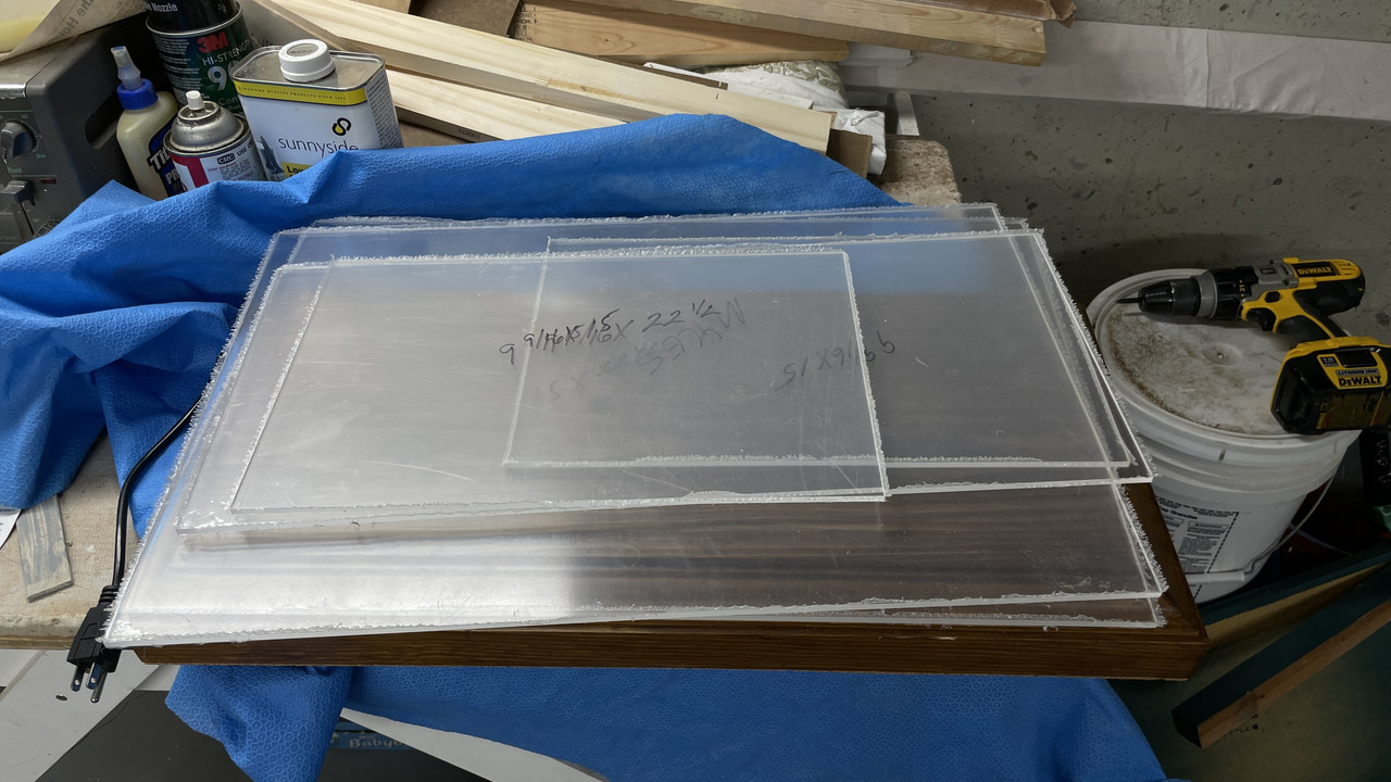
Thanks! And the tips and tricks are mutual. I got two terrific tips on gluing Plexiglass that are going to solve a big problem for me. When I do that part of the job, I will elucidate.

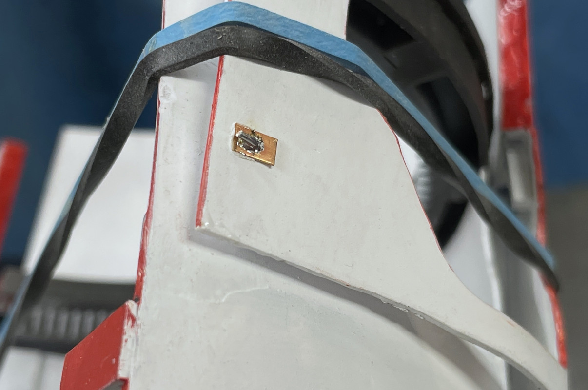
First of all, the 1/16" pins plus J-B 30 minute epoxy did the trick. Those joints are not solid and will not let go. I ended up filling them again after I ground off the protruding pins and did a little bit of plastic damage. I have some touch up painting to do… again, and that will finish this up FINALLY.

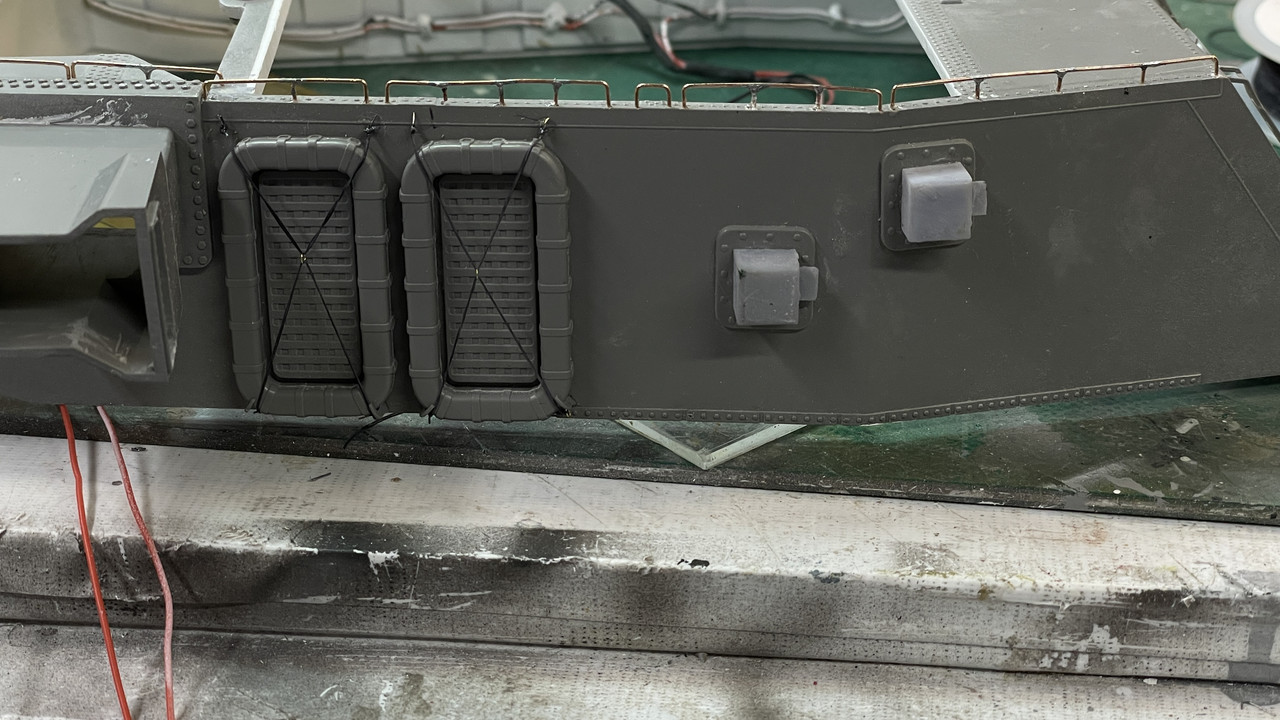
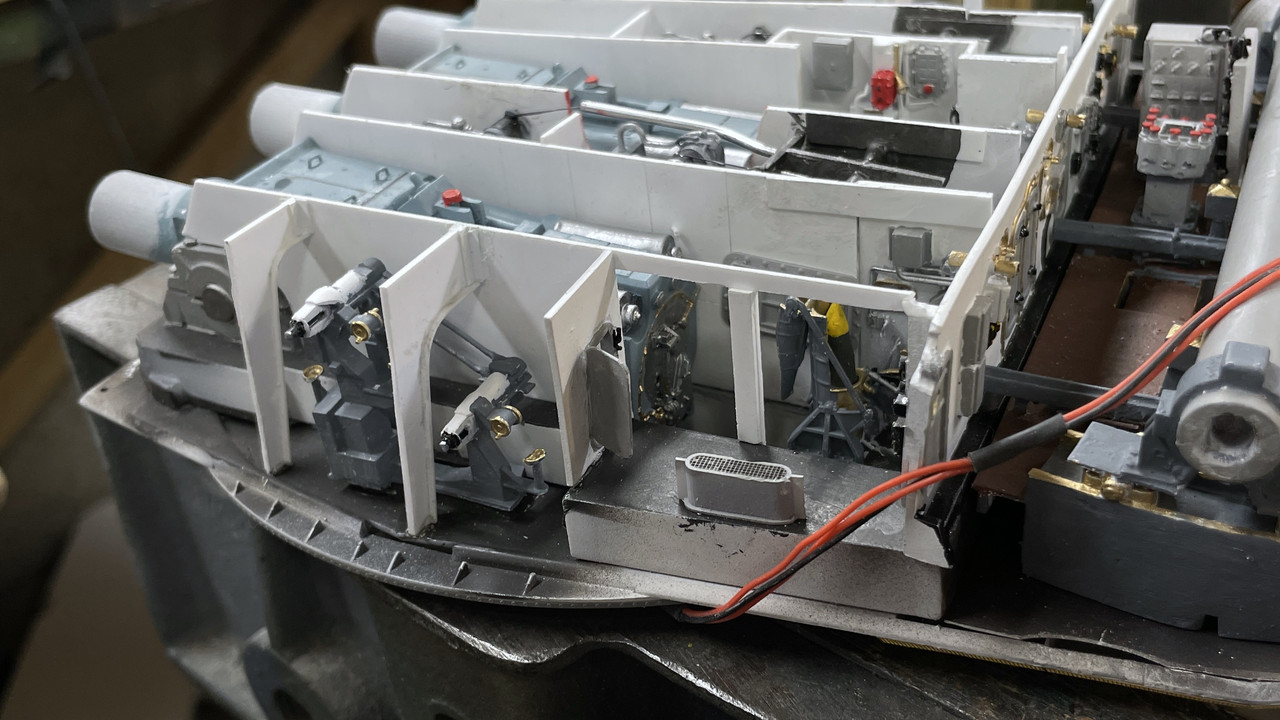
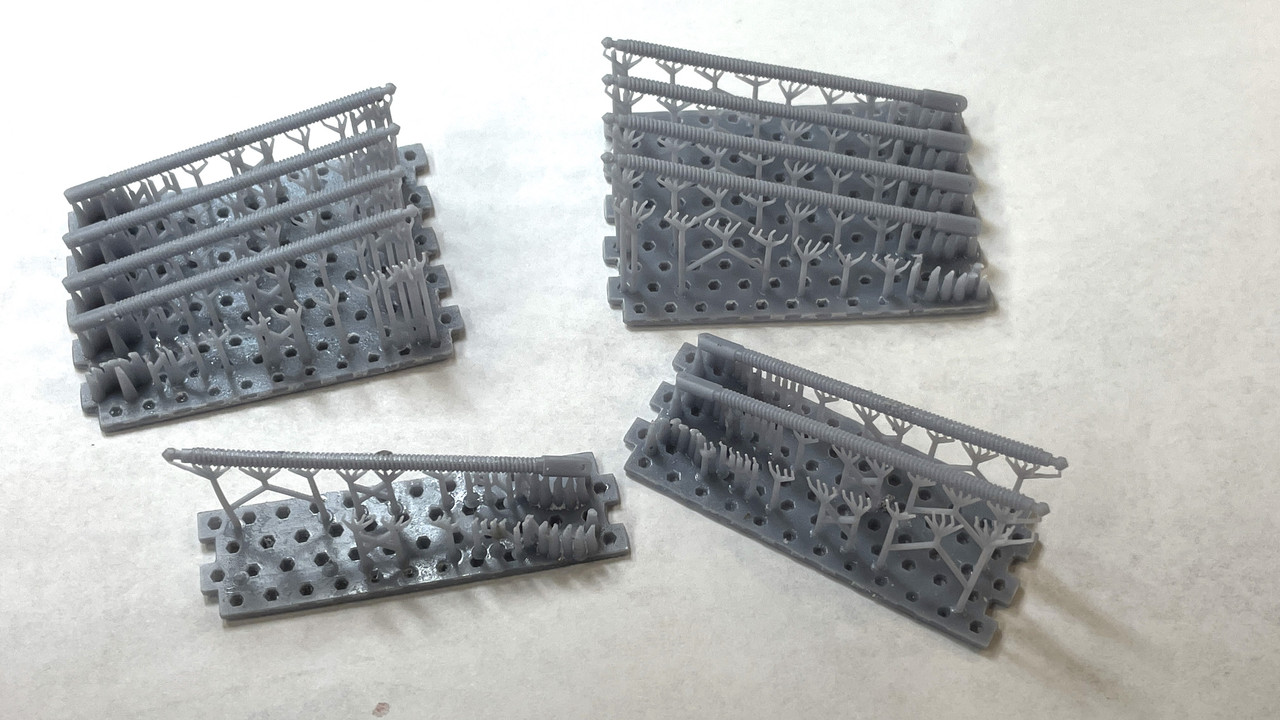
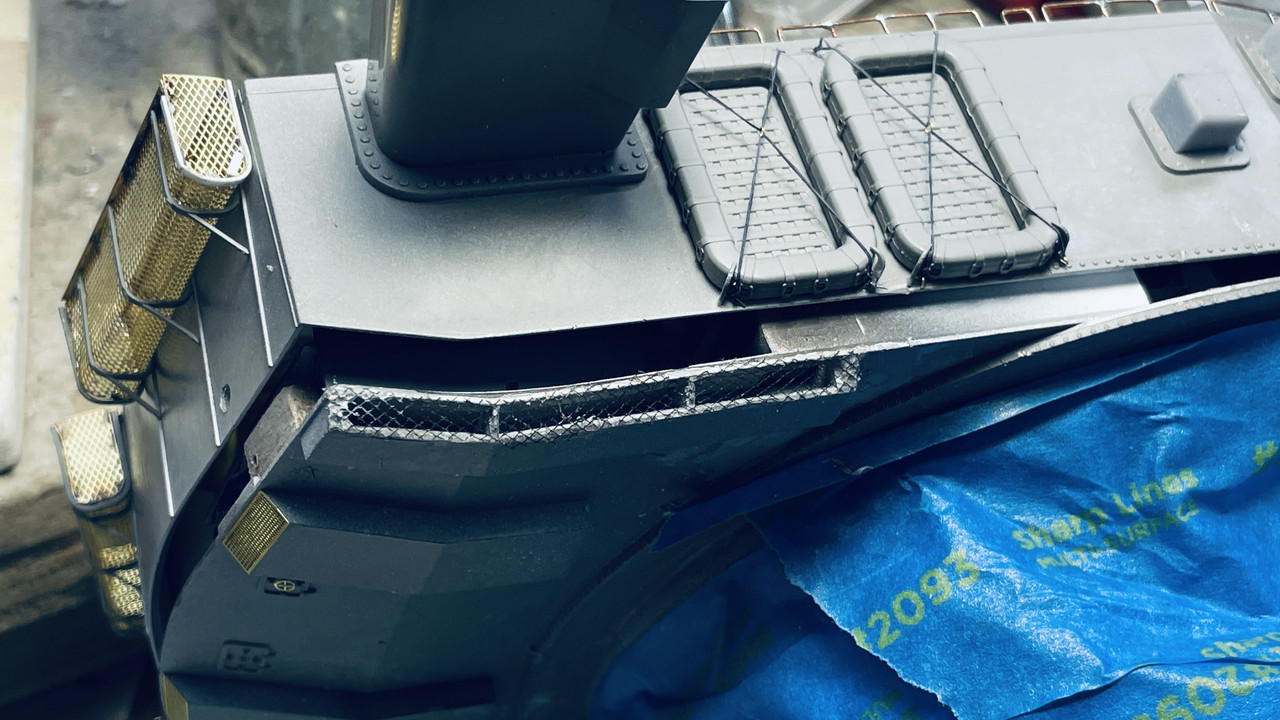
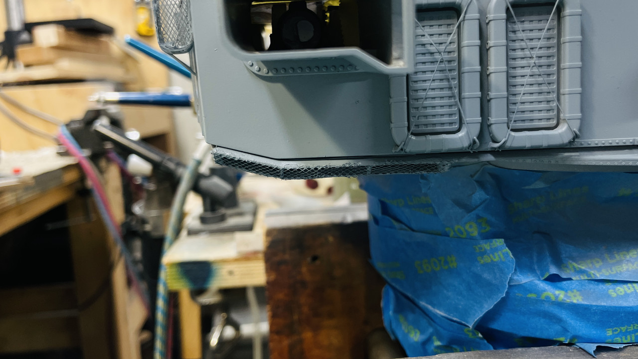
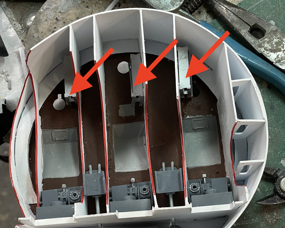
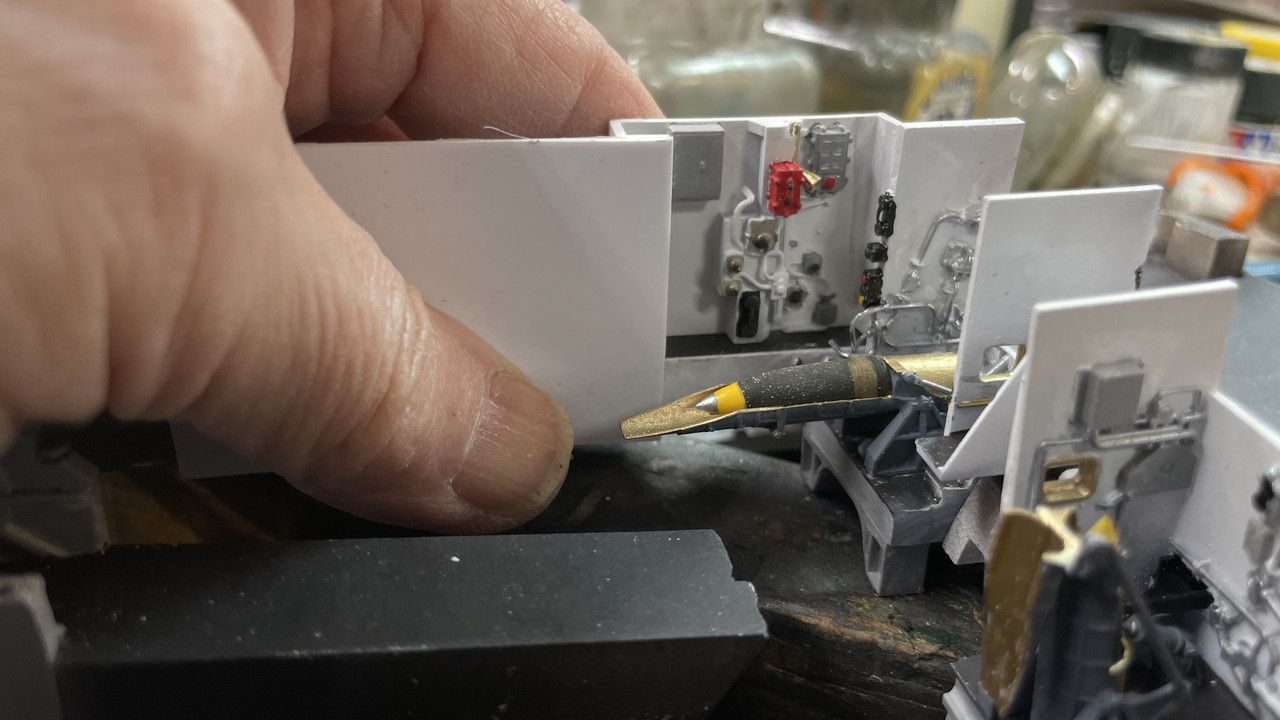
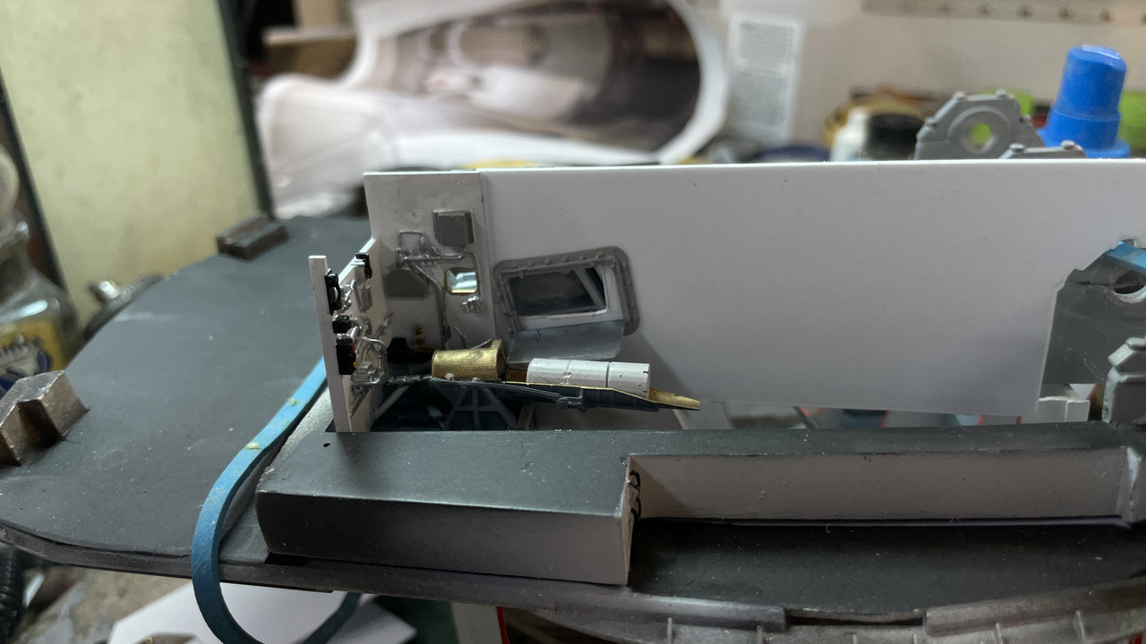
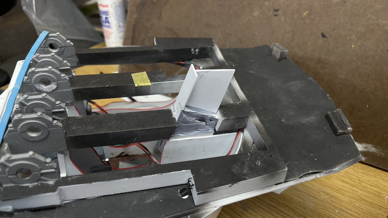
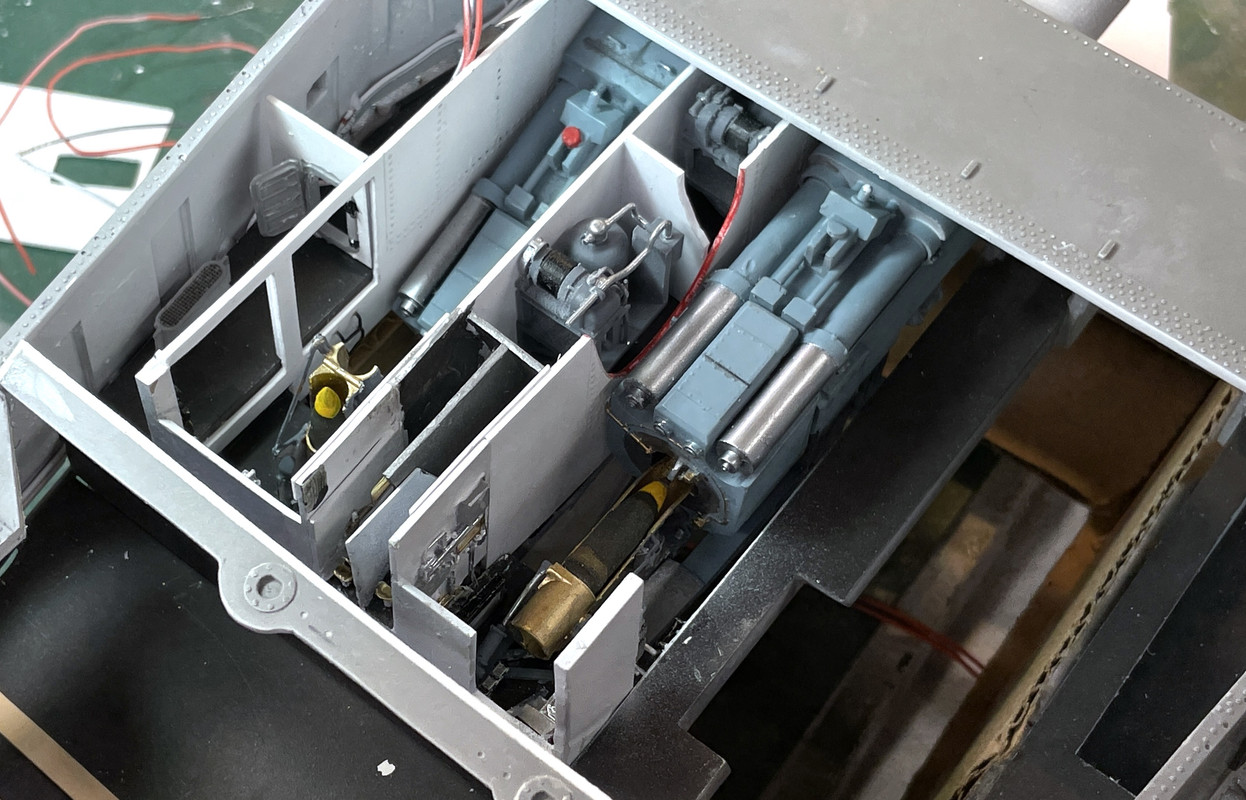
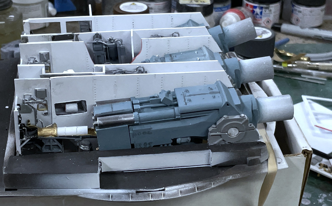
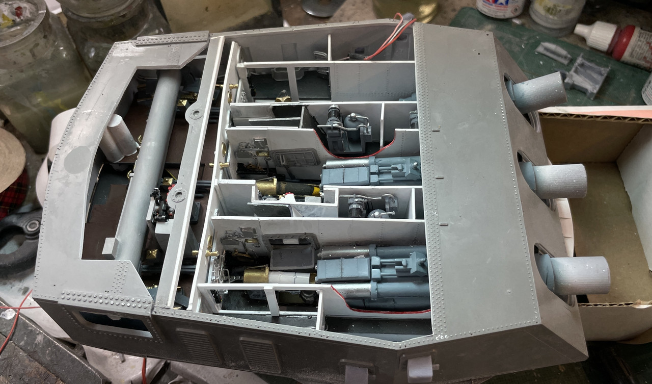
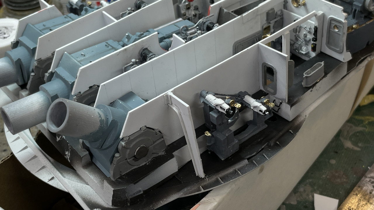
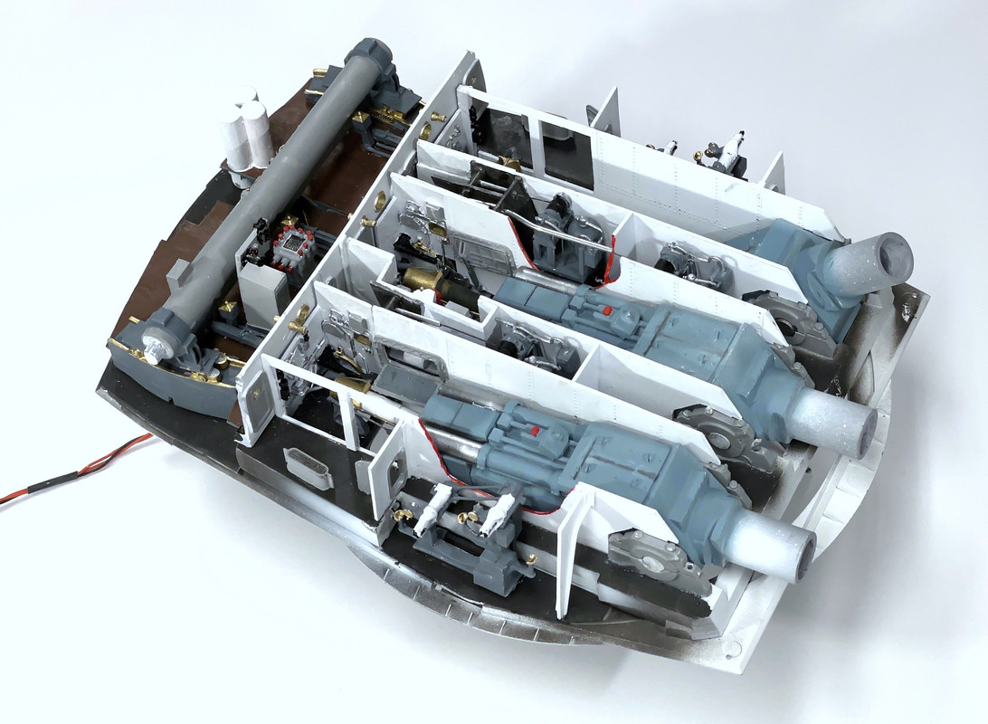
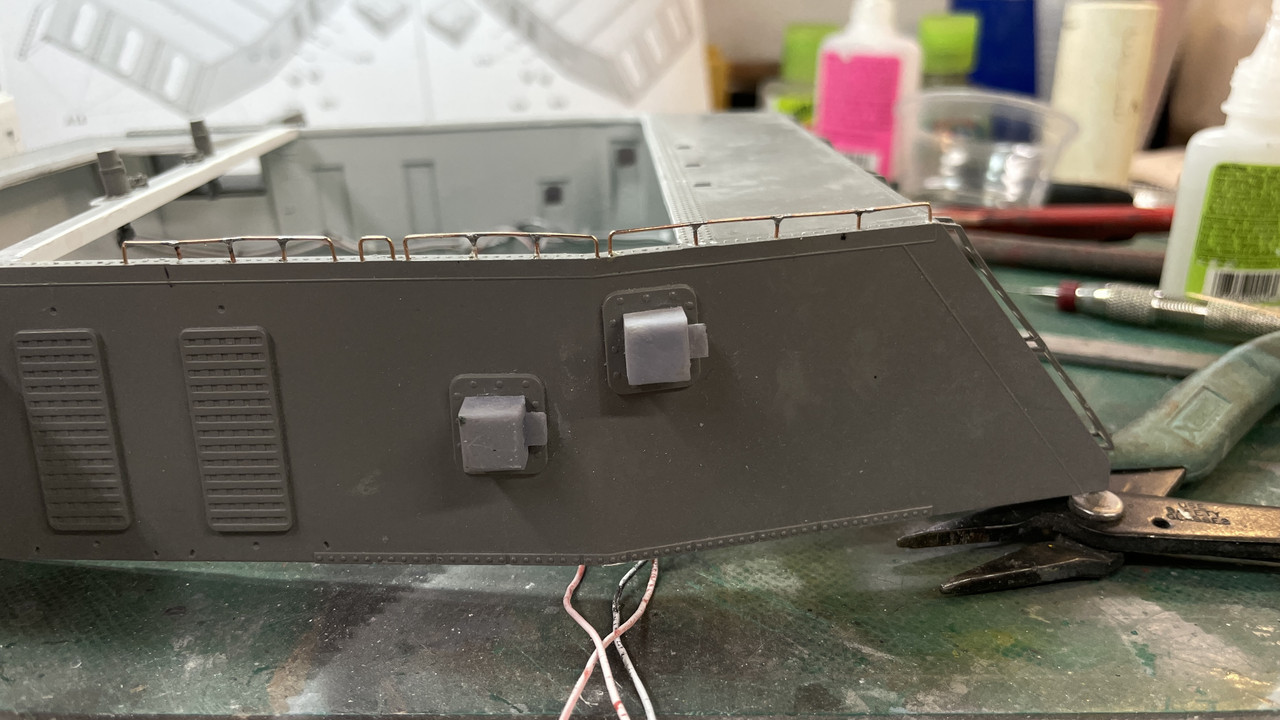
I painted the primerman’s platforms with Allclad metalllic and then glued them onto the pan deck partitiions. There was much more surface area on the flanks of the styrene angle, than on their little tiny feet. I first tried to use clear silicone caulk as an adhesive since it might have some give and not be too brittle, but the stuff didn’t work at all. I removed all of it and then used my standby gel CA. The one on the right side of the image (left gun), is in the way of the projectile chase and I’ll hack at it to get the clearance. This one is out of sight behind the bulkhead so not matter what I do to it, no one will ever know, other than the myriad of people that read this stuff on four fourms.

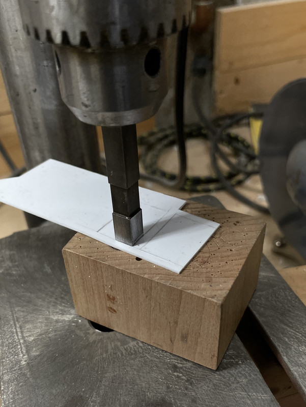
I drilled a hole in the back compartment of the e-deck to pass the pan deck’s wiring down into the bowels of the structure. I

t was now time to join these two critical components. I’ve shown this months ago, but there are reinforcing ribs under the pan deck base to help minimize warping (it worked…sort of), and I then had relief cuts all over the e-deck to nestle into these ribs. The p-deck base did warp some with the midsection bulging downwards and that made for some very repetitive fitting steps to relieve all the high spots on the e-deck so the two would nest properly.

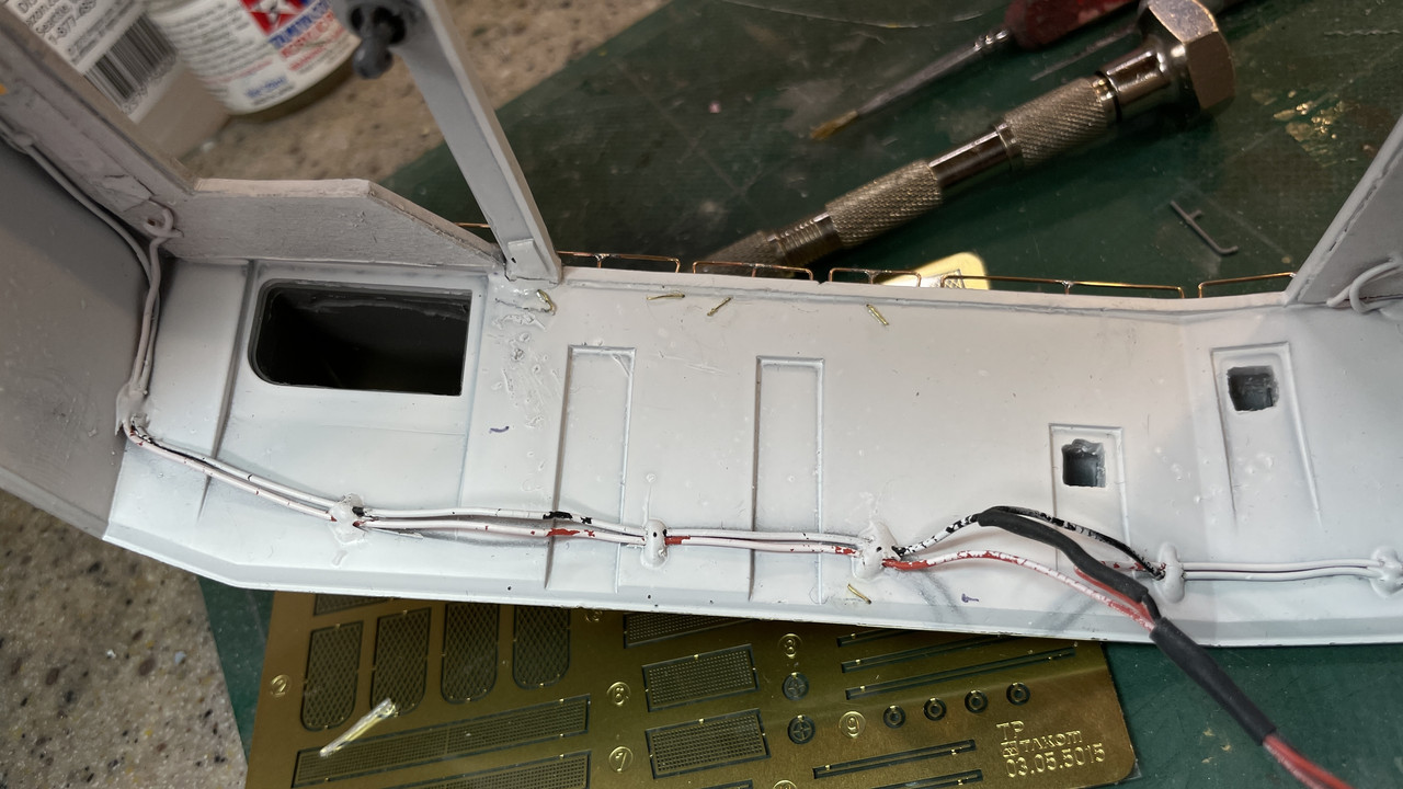
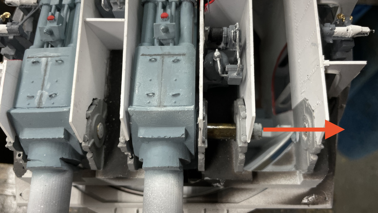
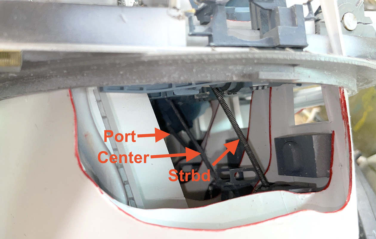
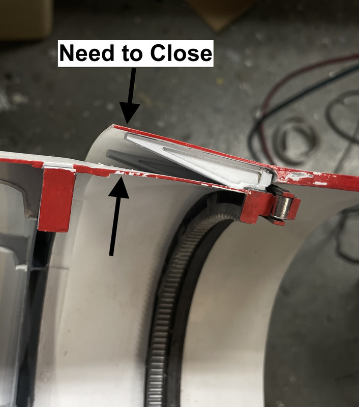
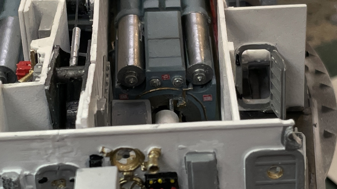
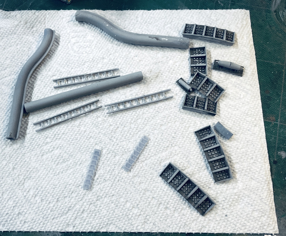
But lately, the two were not fitting correctly. The back section did, but not the part where the pinion gears lie. Today I spent a lot of concentration and using my iPhone’s light to see if I could find what was impinging that was keeping them apart. First i found that the hydraulic lines running up to the p-deck were too tall, so I chopped them down, but the fit did not improve.

Finally, I found the culprit. When I rebuilt the bulkheads that surround the pinion gears, I neglected to cut the relief notches into the new parts. It was a small triangle of the new material that was too high. When I trimmed it, it again fit as it did before.

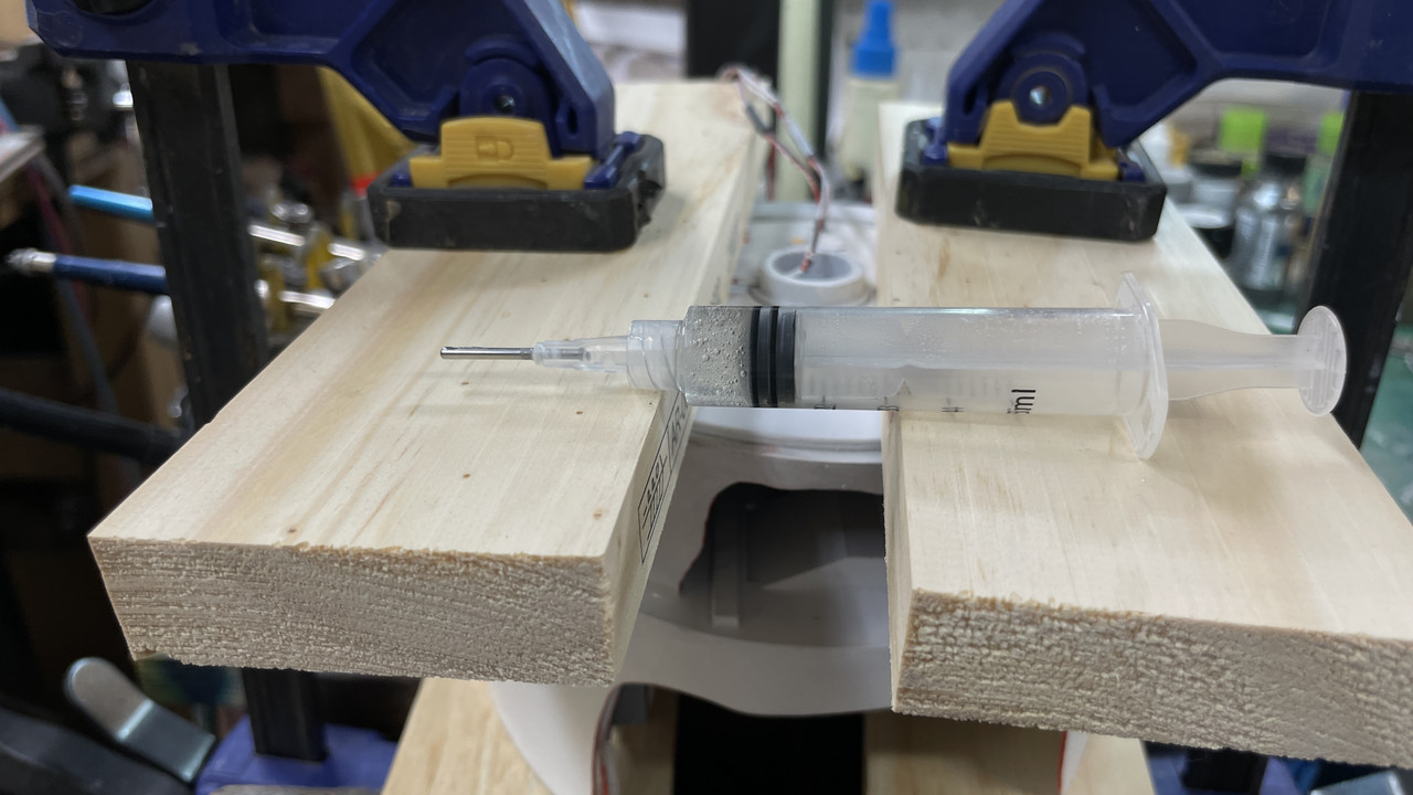
It needed some concetrated and even pressure to hold the two decks in close contact so I could apply the epoxy. Again, I resorted to using a disposable syringe to apply it precisely.

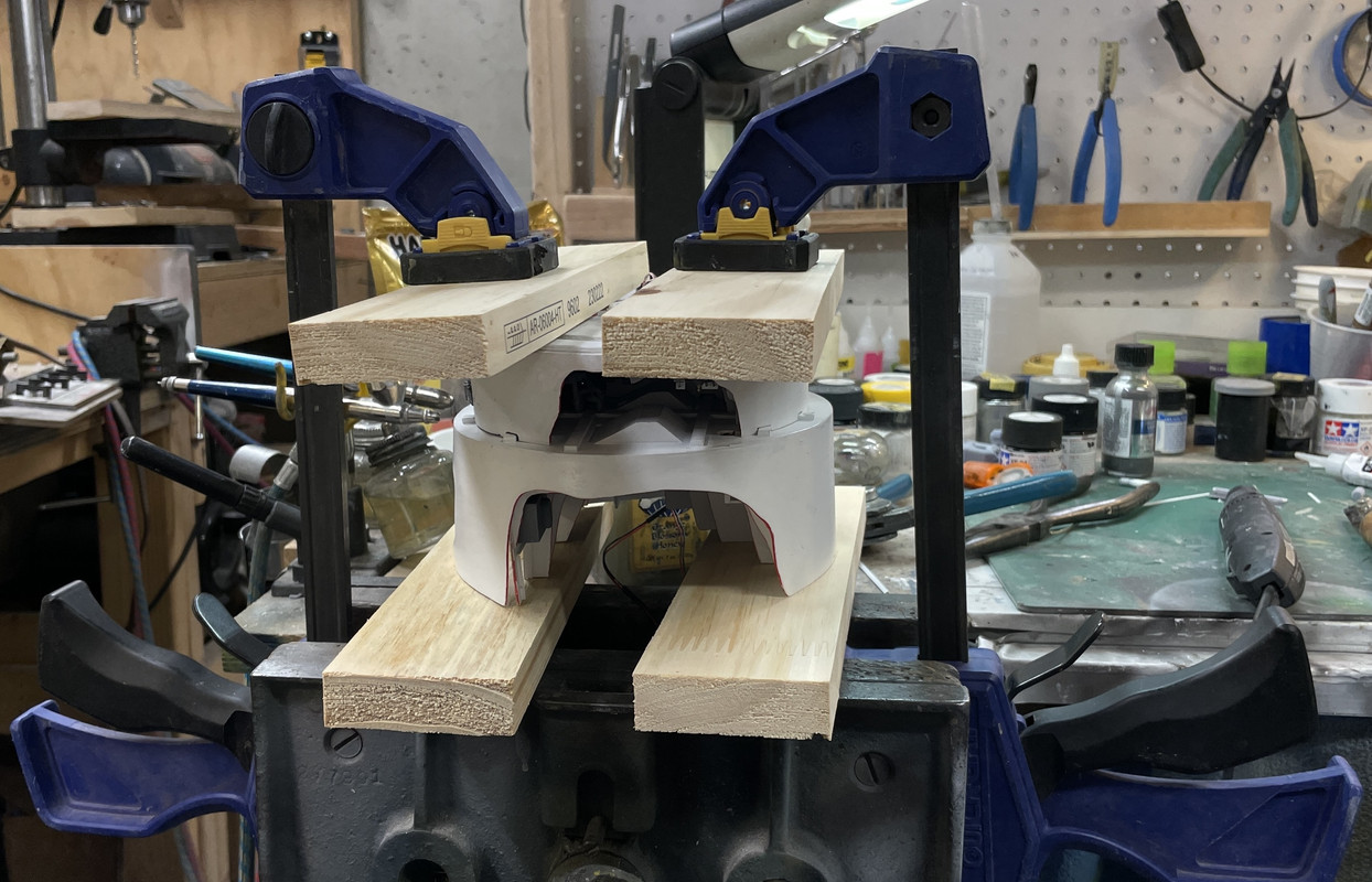
I arranged to big Quickie clamps with some blocking to get the joint tight. I had to be very careful since the clamps could exert enough force to crush the e-deck’s side walls. I tightened until I started hearing some ominous creaking sounds and then backed off.

Here’s the syringe that applied the epoxy. I purchased a set of syringes of different sizes and interchangeable tips just for this purpose from Amazon.

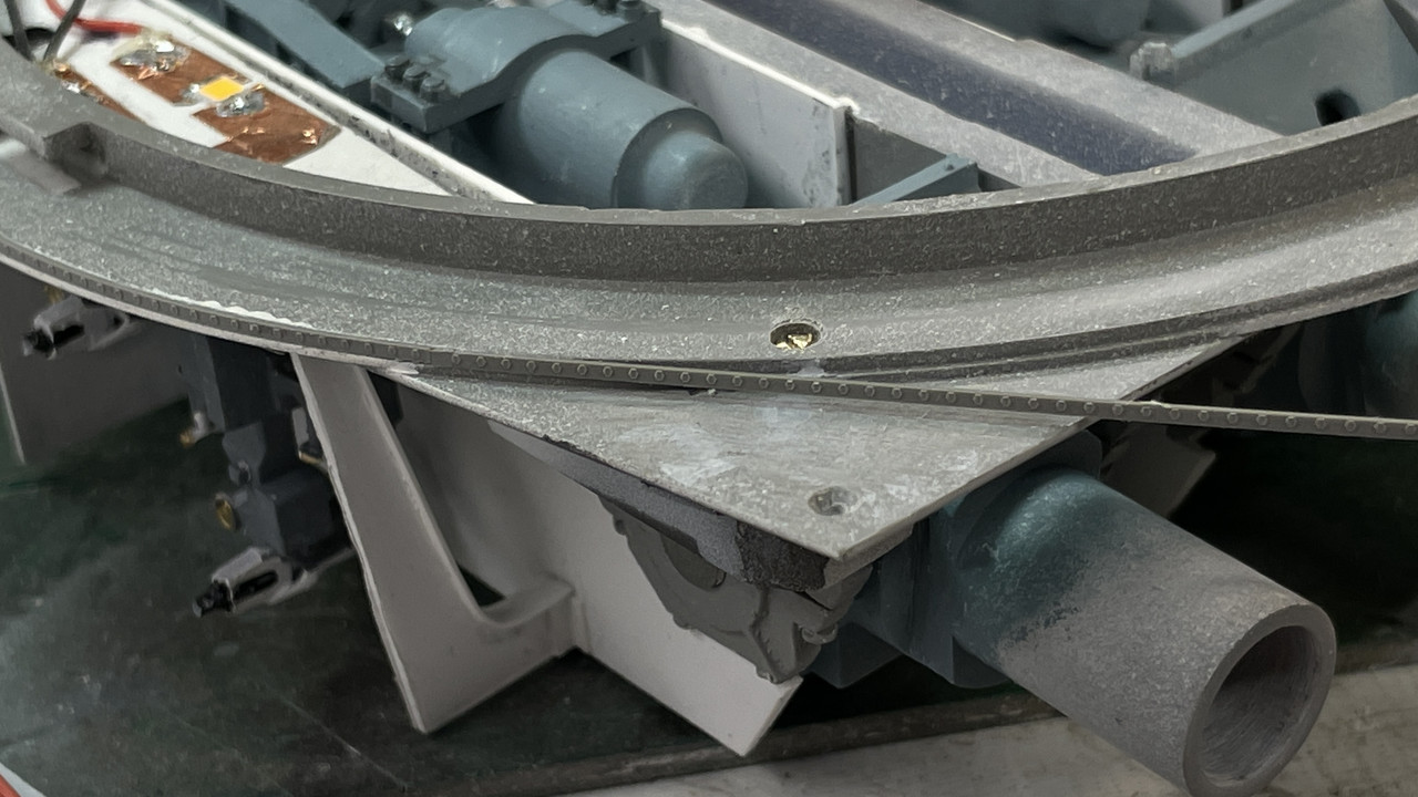
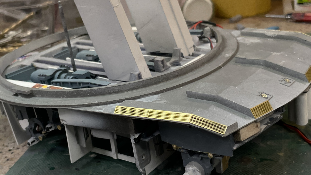
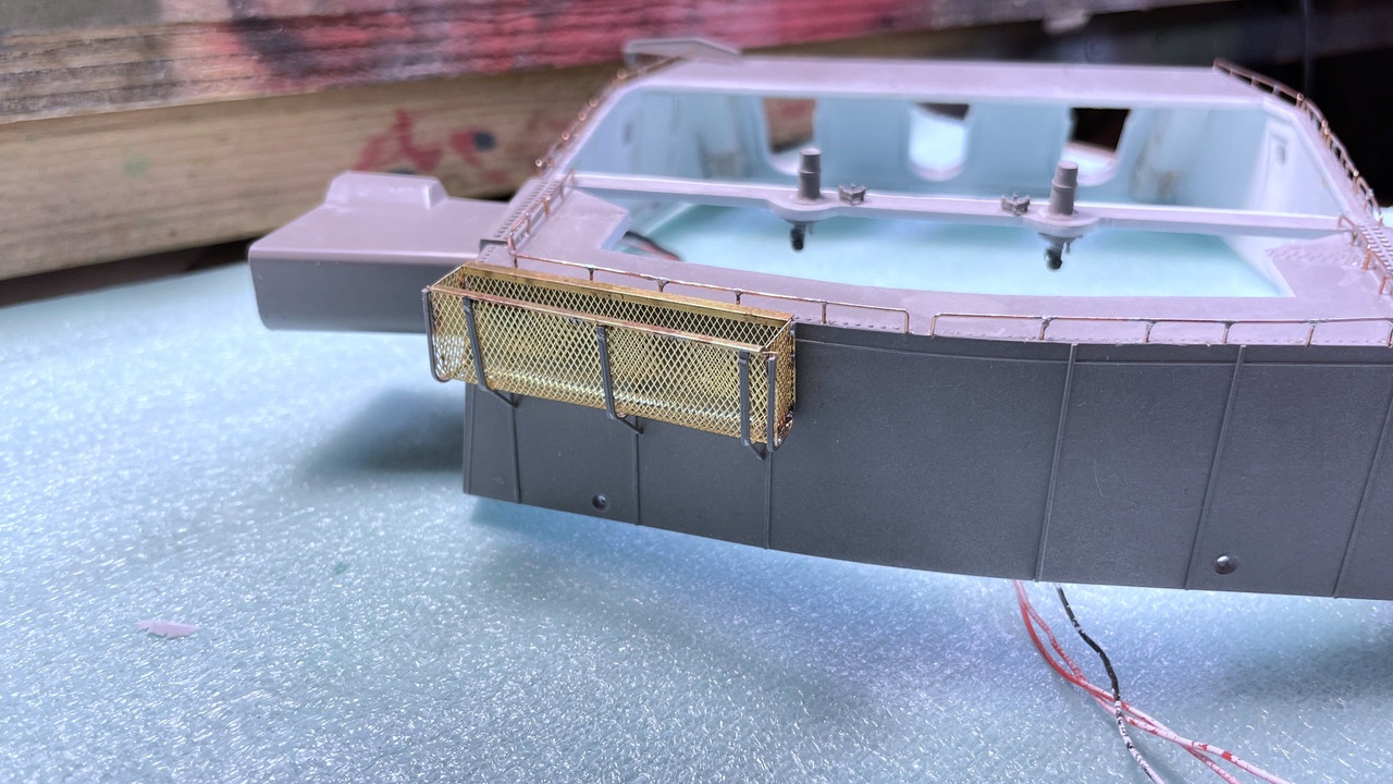
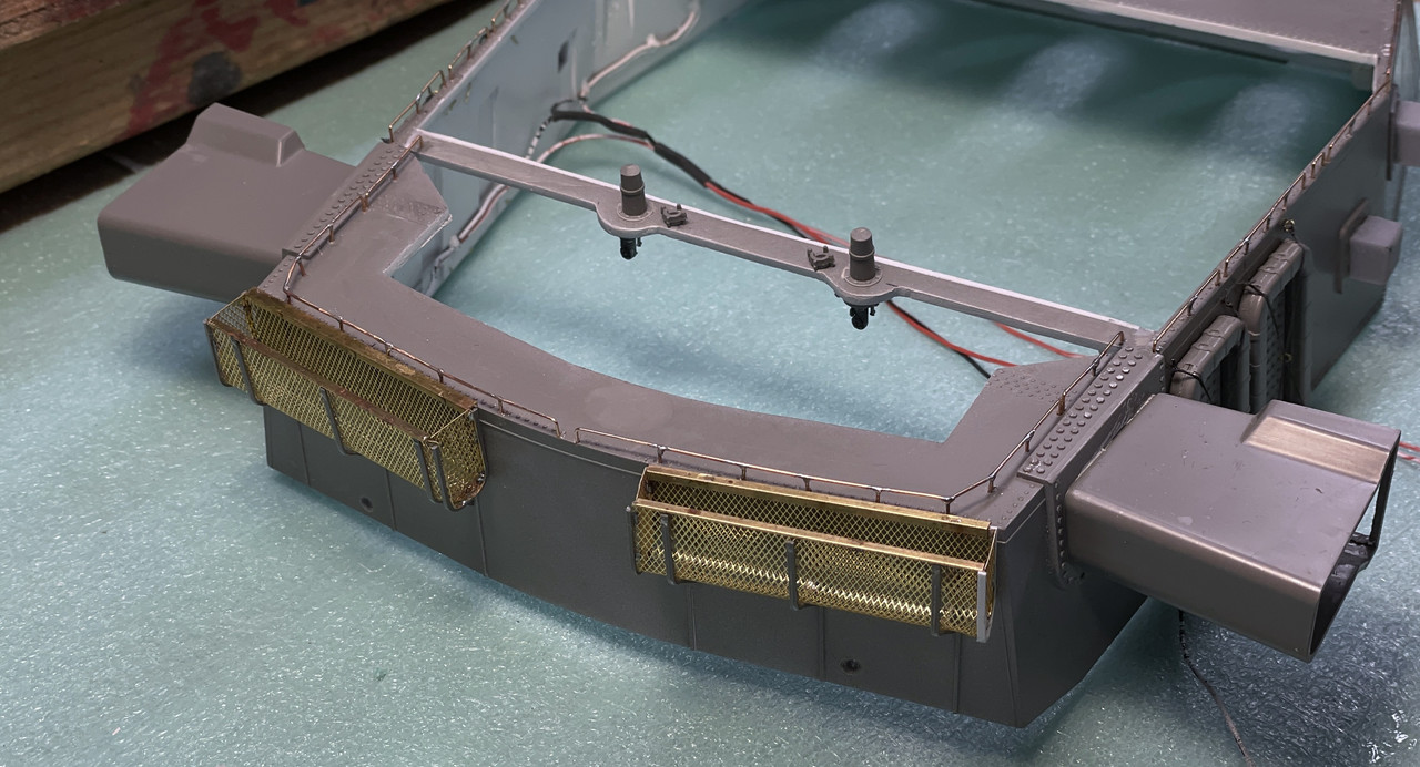
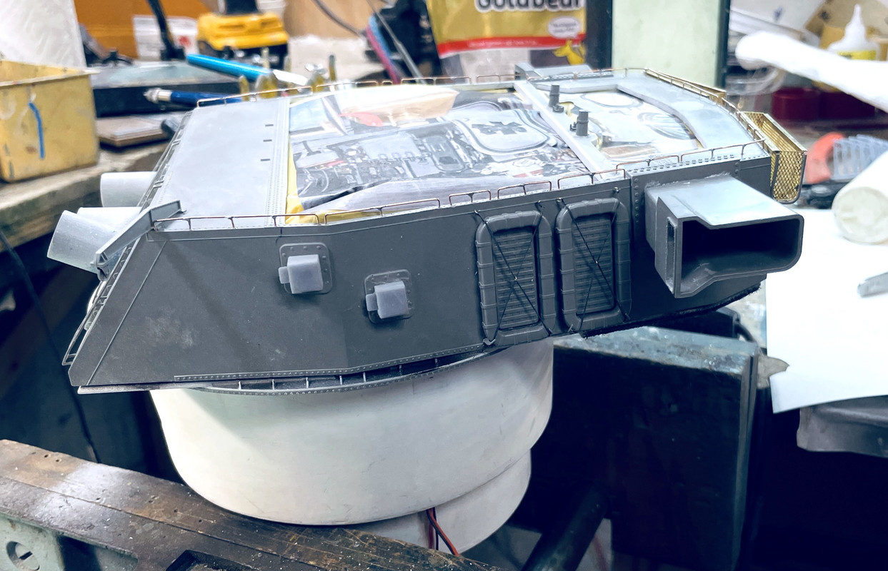
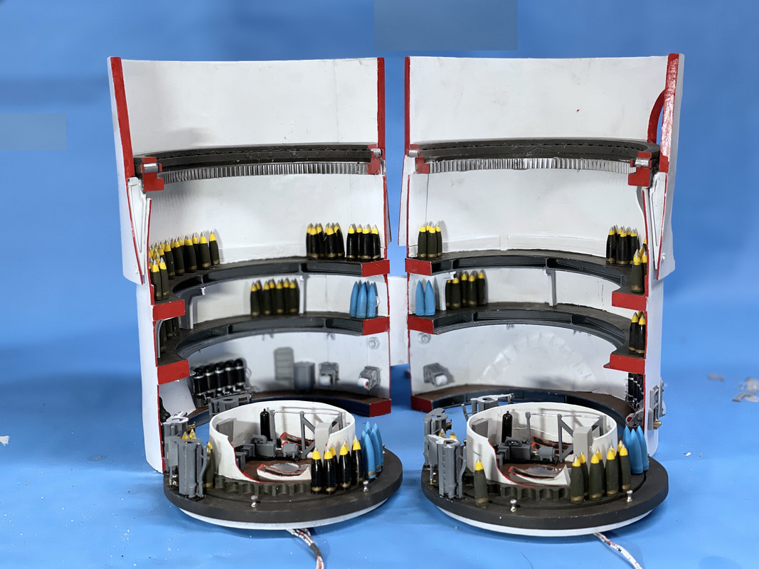
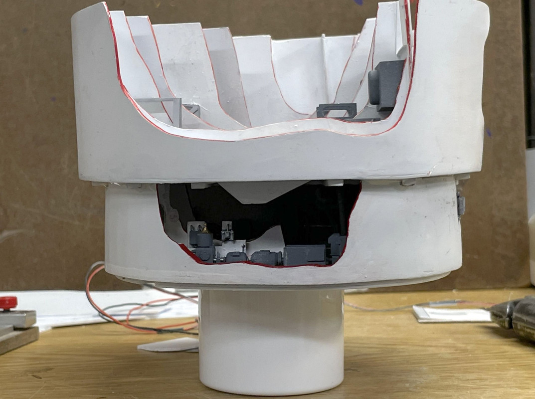
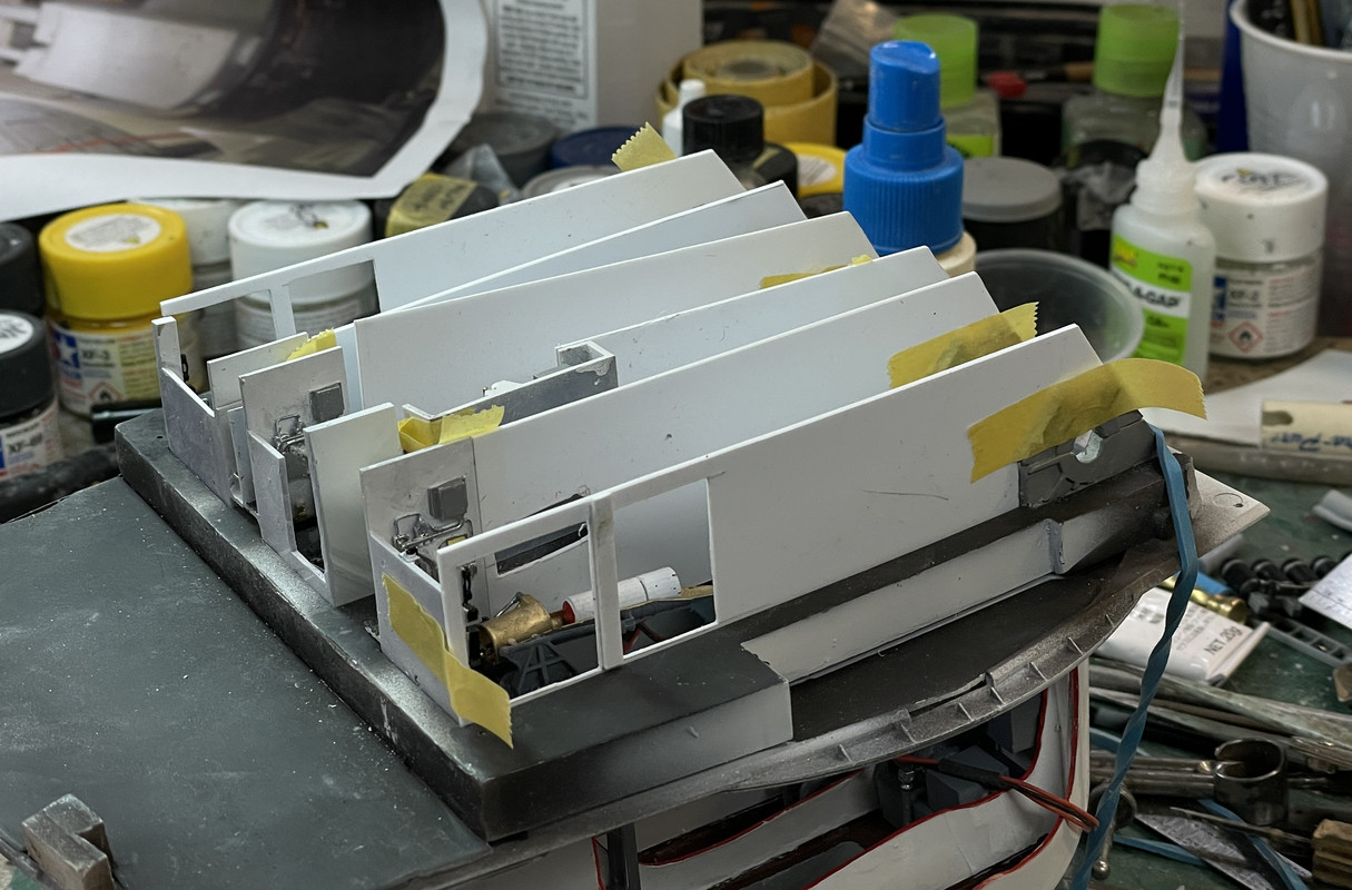
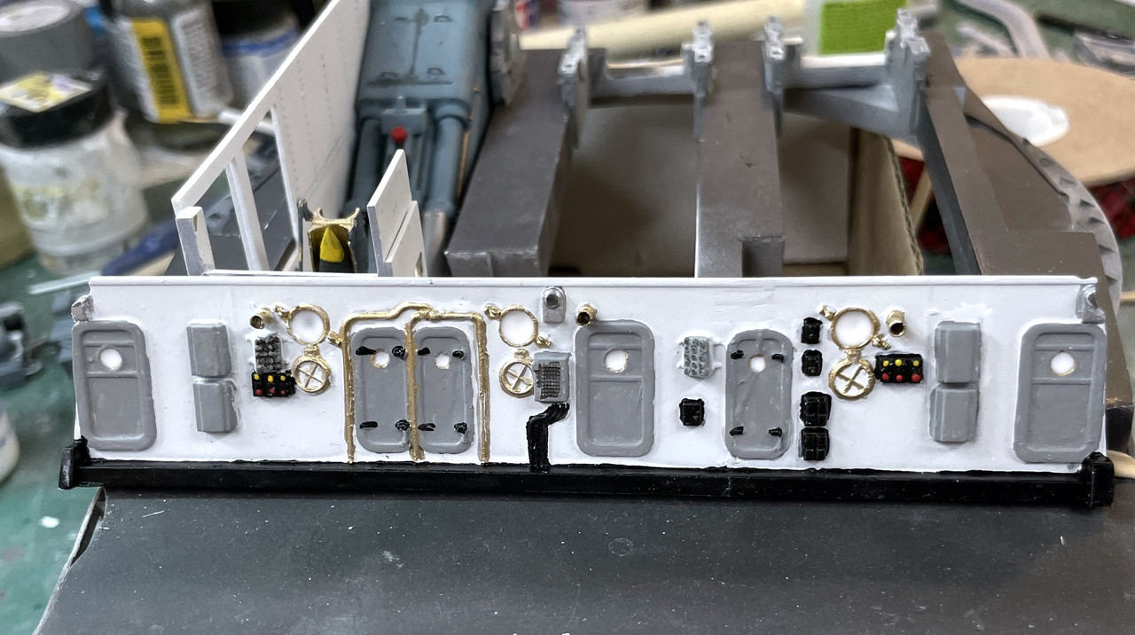
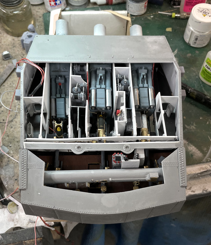
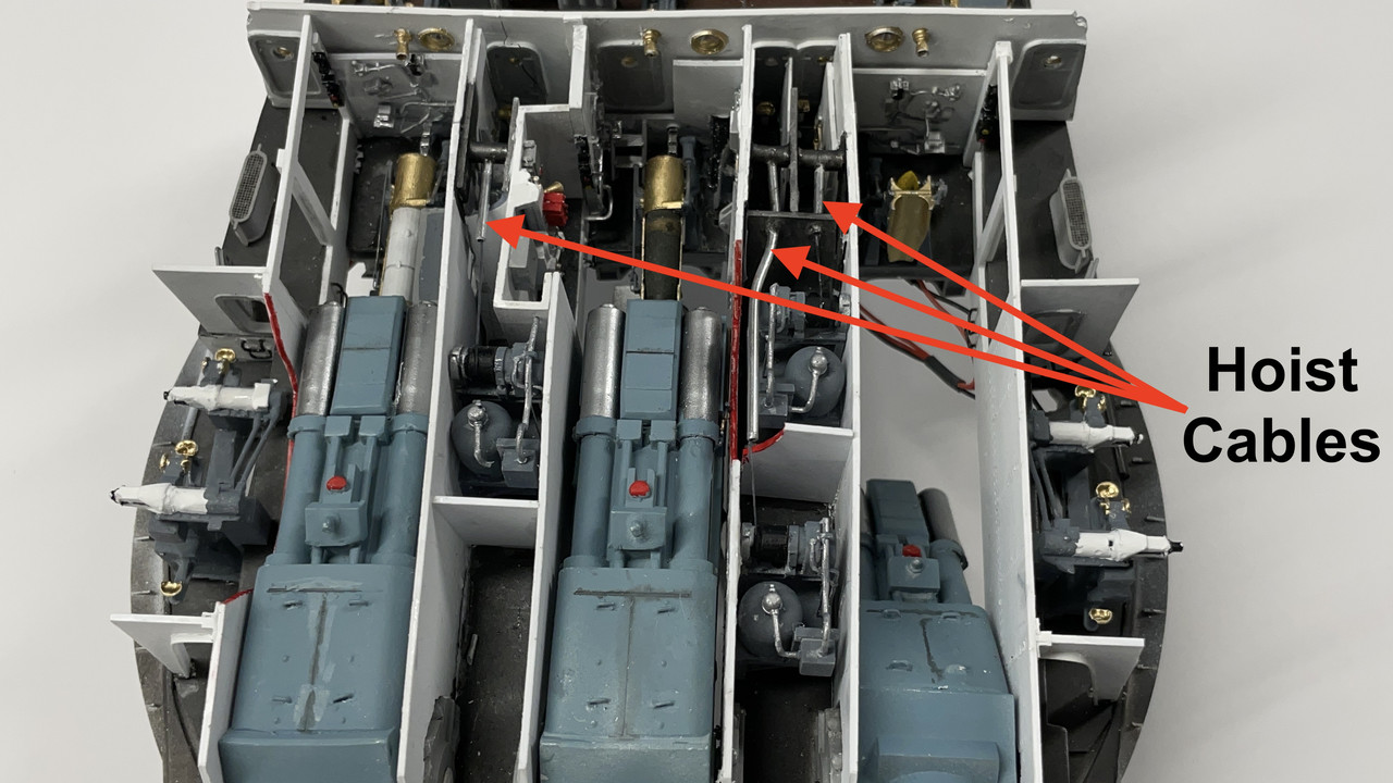
Here’s two views of the final joint. There’s just a couple of spots that will need cleanup. I will paint the epoxy next session when it’s fully cured.

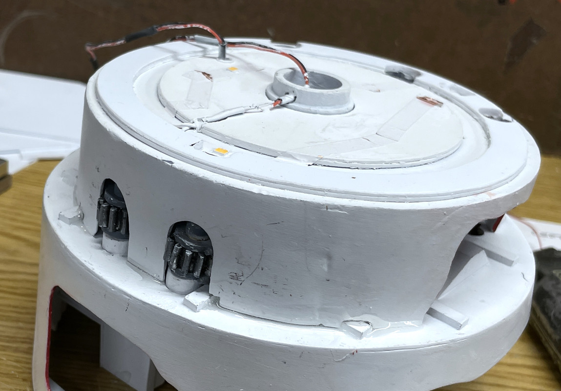
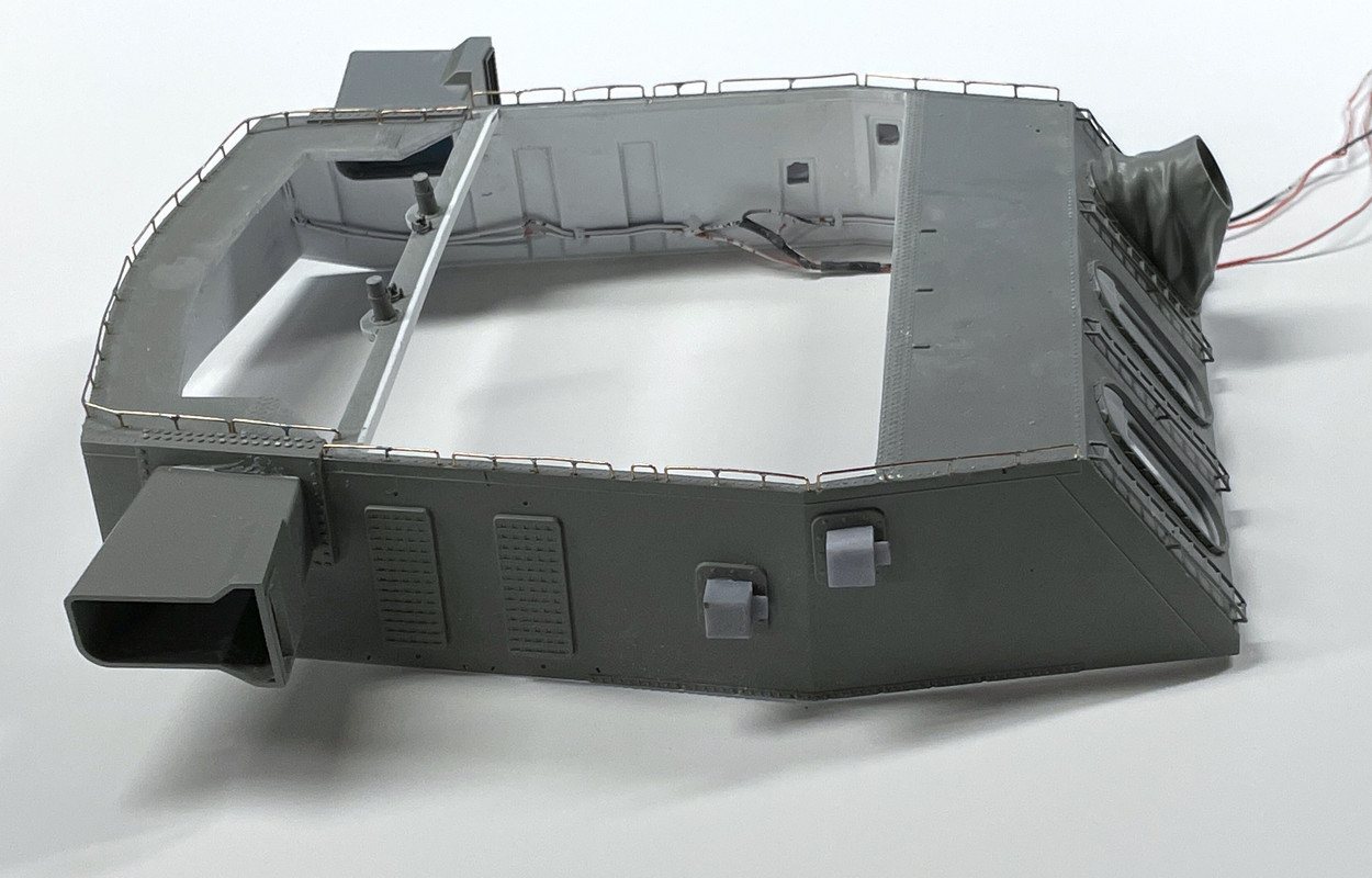
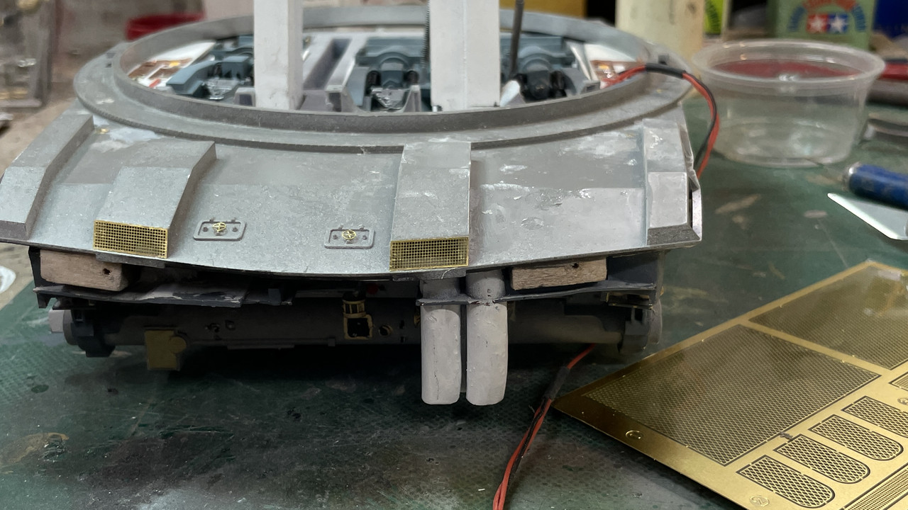
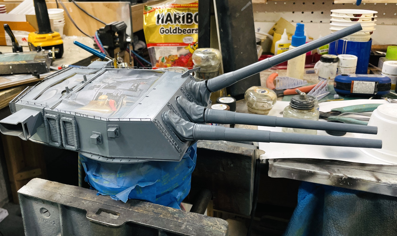
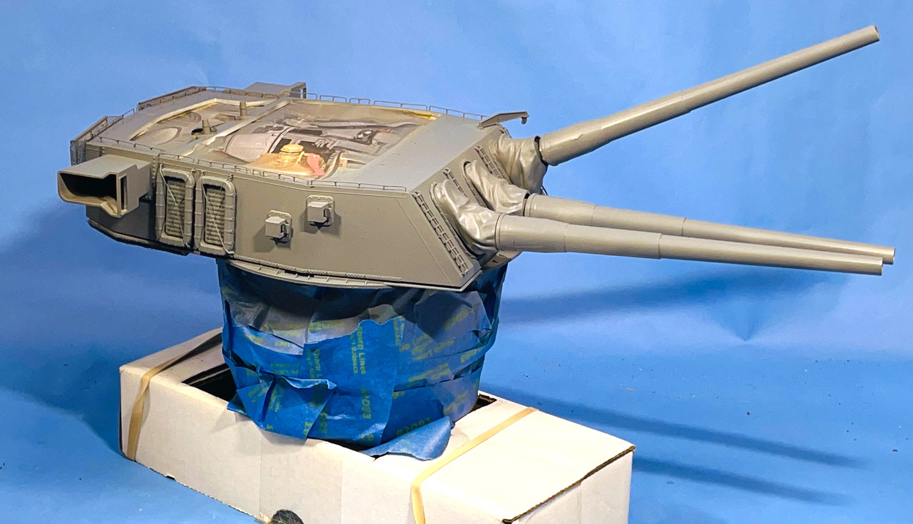
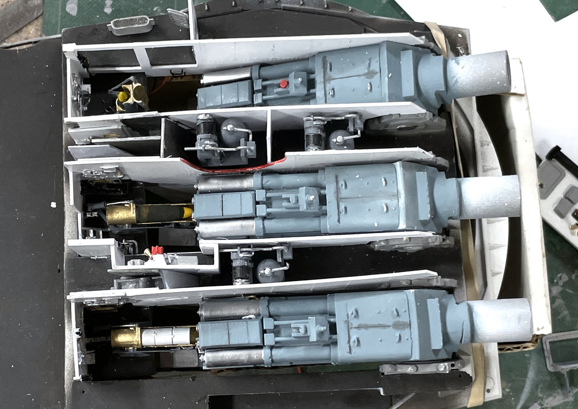
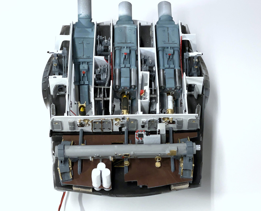
Here’s a normal view of the assembly. This was the singularly most challenging of the joints since it wasn’t stabilized by the central column. The other decks don’t even have to be glued together to be concentric.

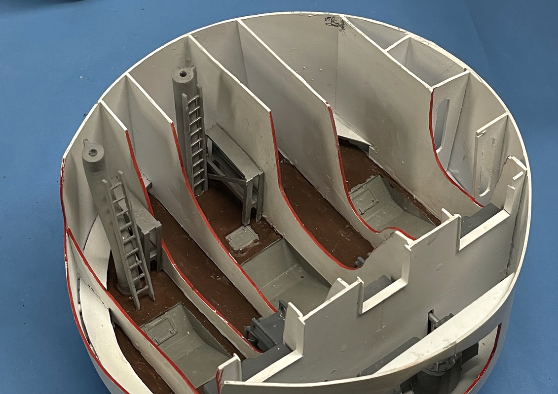
It’s mighty dark in there… needs some lights… oh… wait… there are lights. Glad I thought of it ahead of time.

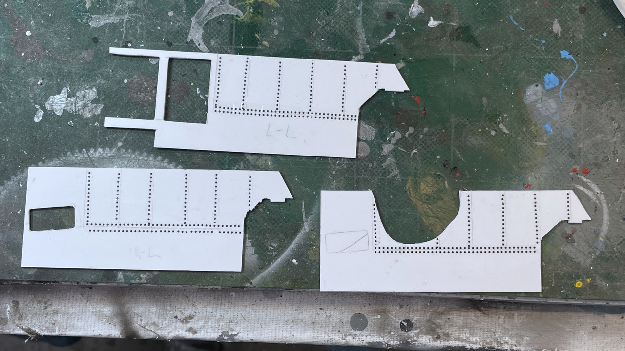
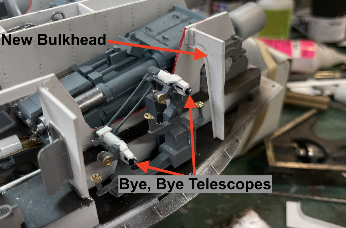
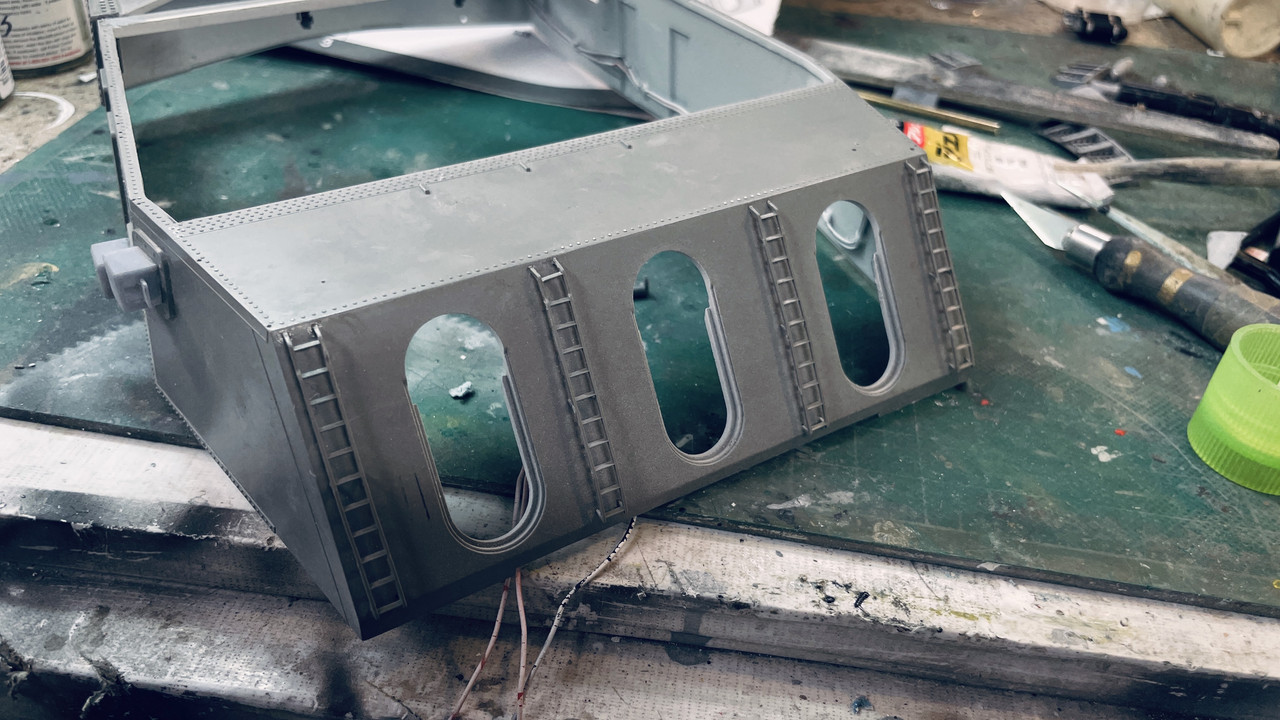
I was now ready to finally finish up the gun house and create the six bulkheads that separate the gun pits. I had drawings of these that were made a long time ago before all this stuff was actually created, but they were pretty close. The did nto reflect the new learning of how people entered and exited the gun pits, especially the center gun alcove and the big opennings in the side guns.

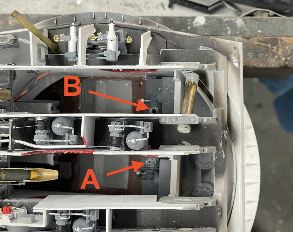
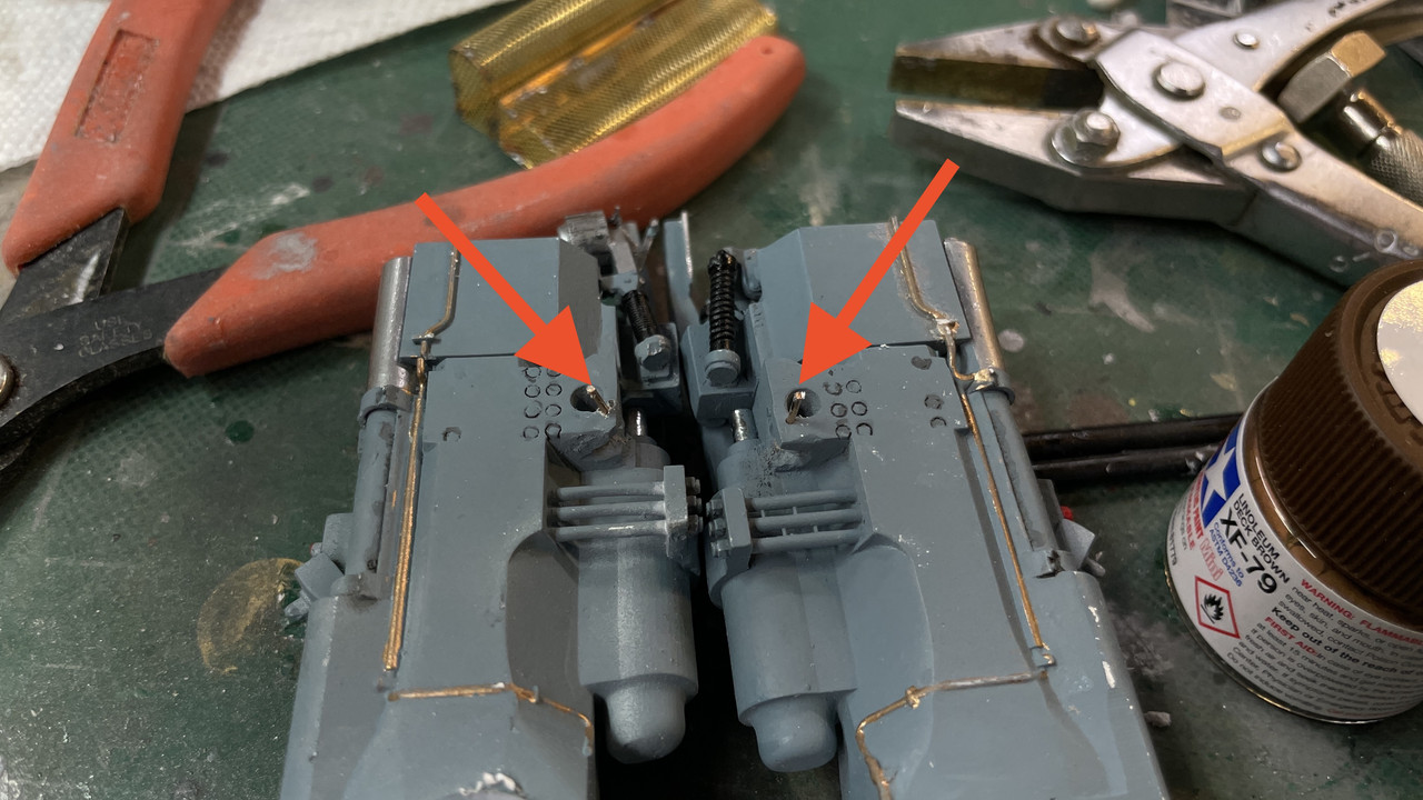
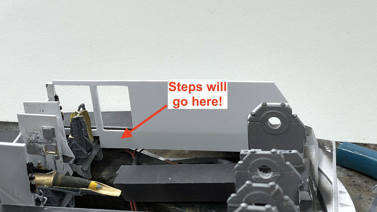
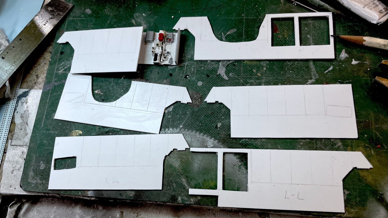
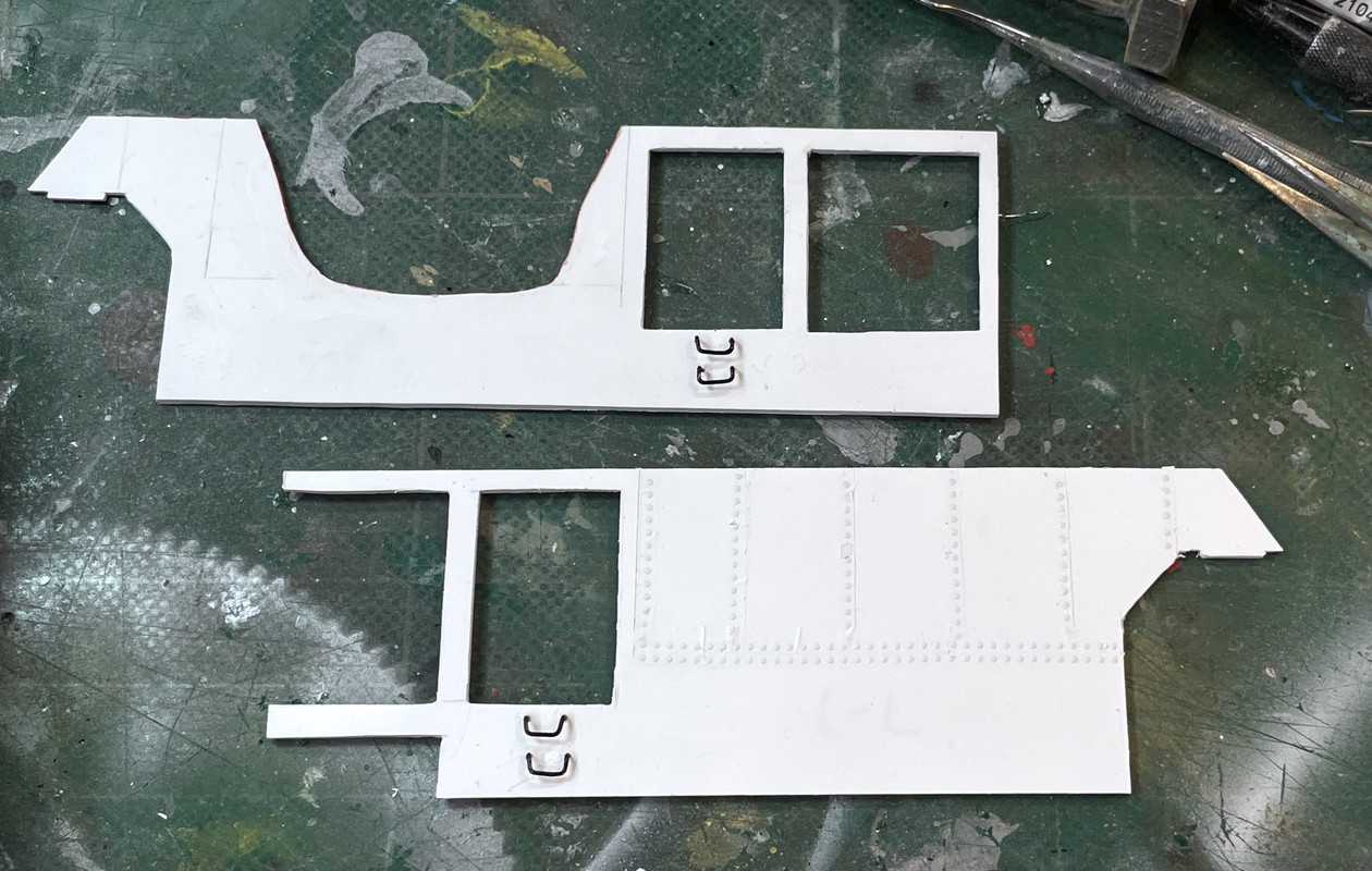
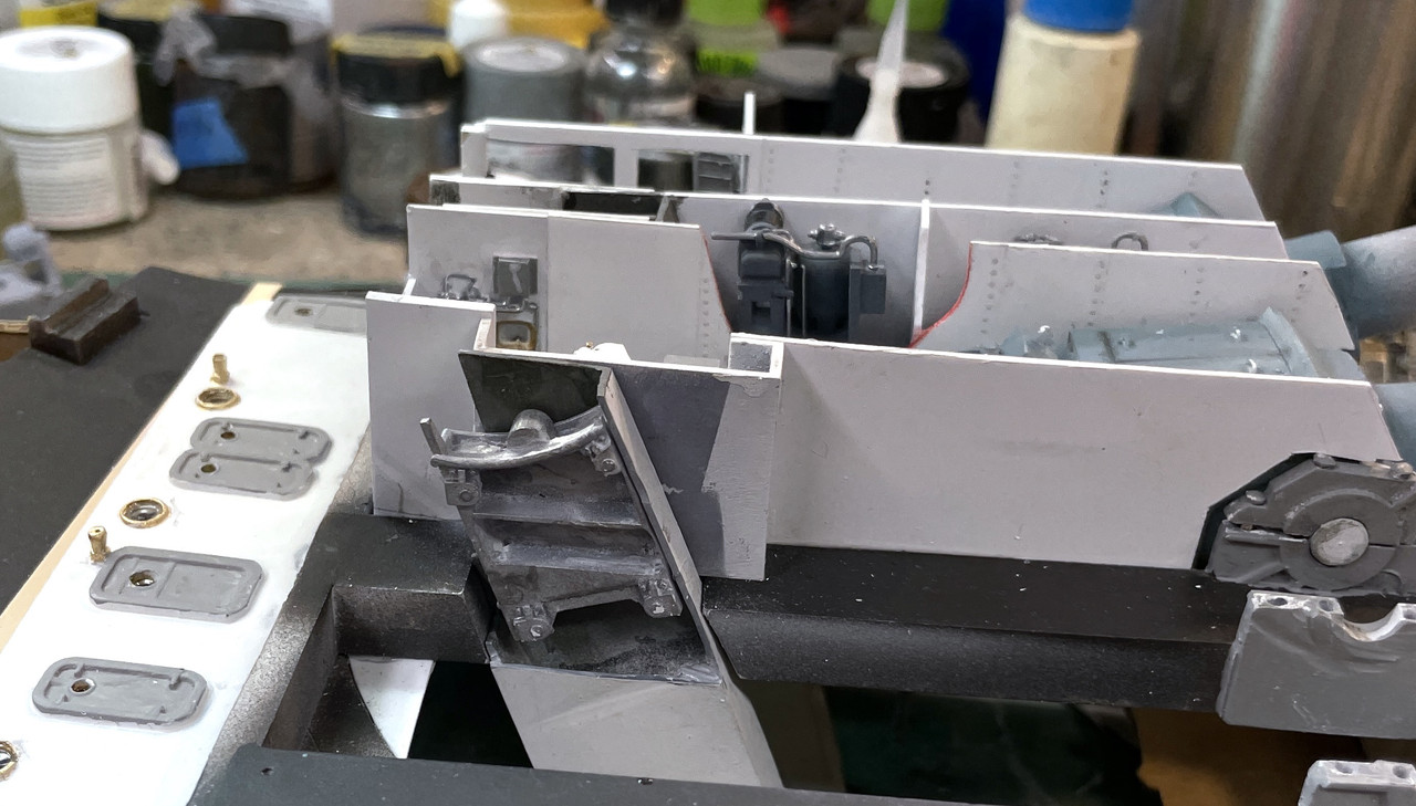
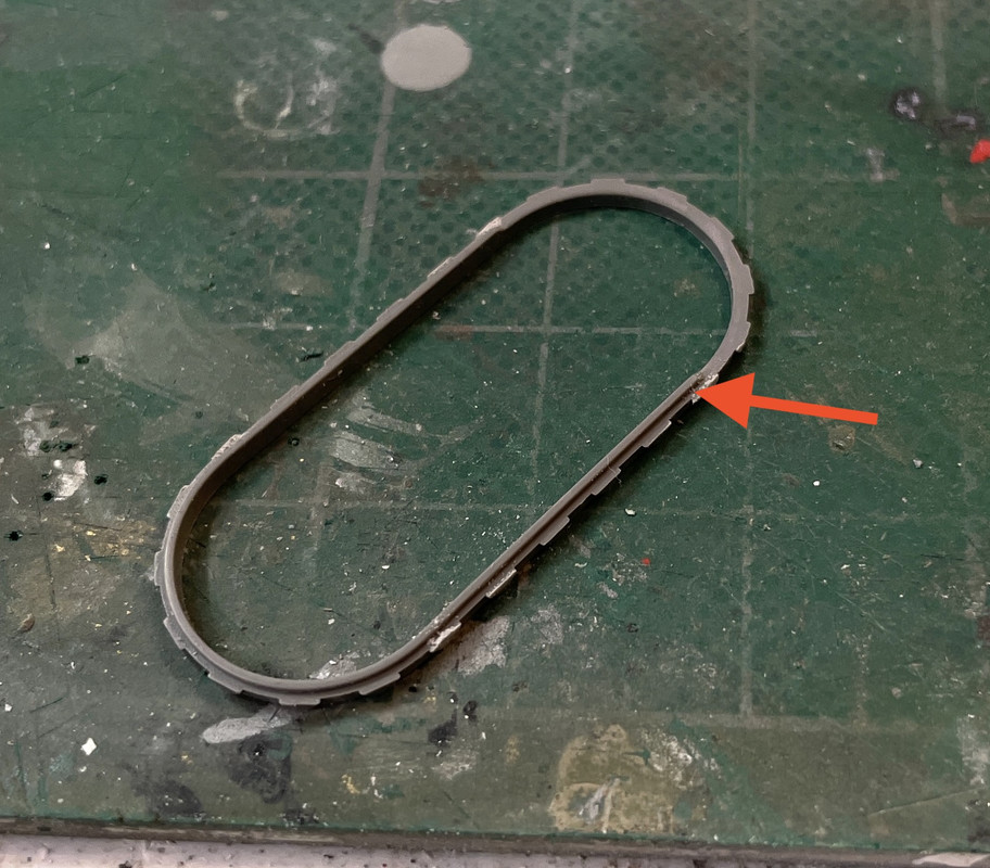
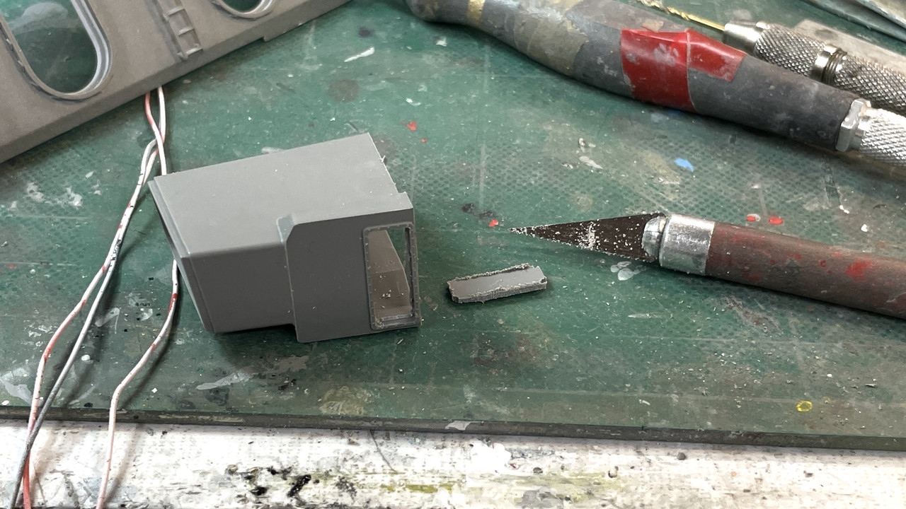
Here’s the right side gun’s left bulkhead now fitted to the little bit of it that’s included in the gun compartment printing. I noted on this picture where I’m going to re-attach the foot rungs and will do it off the model so it won’t be so difficult.

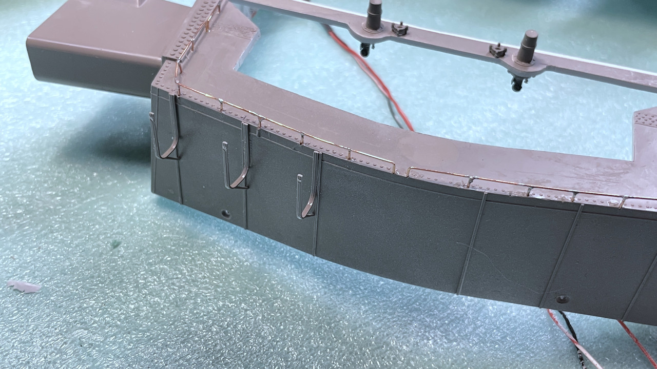
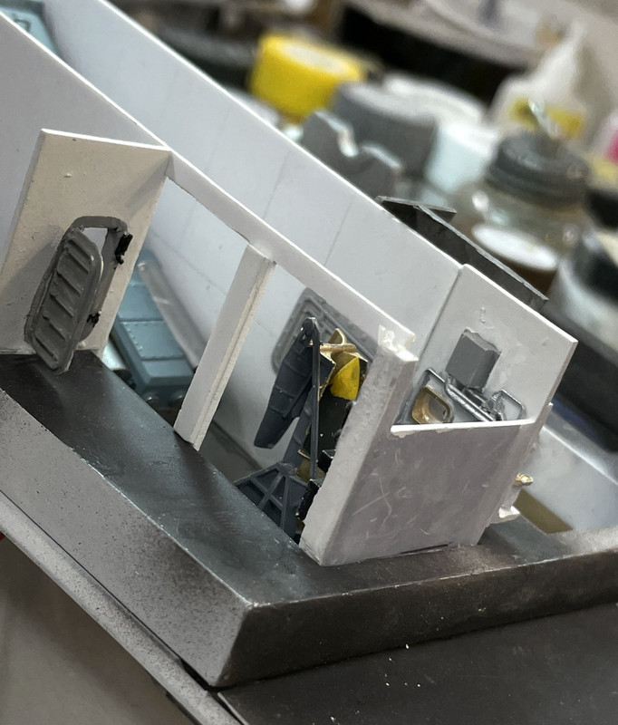
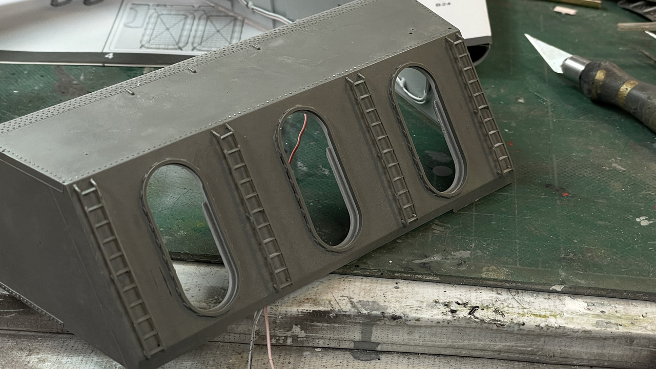
And I built the center gun’s right bulkhead and attached it to the alcove. Here is it test fit with the rear compartment. The white sytrene is so nice, I may not paint it.

I have four more buikheads to fit and then I’ll assemble the pan deck to the gun girder, kit base and kit deck part. Once that’s done, I’ll install the gun compartments, powder trunks with the one where the powder car is exposed, the hoist machinery, and the side aisle details. Before I do the above I have to decide whether or not to laminate real wood planking to the main deck.

All in all, it sounds like a lot of work, but in reality, it’s not too much since (I think) all the show stoppers are now taken care of. This is pretty much straight model building, not naval architecture. I should make my deadline.

4 Likes

A nice long Saturday session. My wife, realizing that I have a real deadline on this project, has relaxed the, no-model-building-on-weekends rule. And I took advantage of it.

This was a particularly important session that had consumed a lot of my creative juices. I couldn’t measure the gun house bulkheads until all the stuff below it was done. I needed the pan deck to be stabilized and by gluing it to the e-deck accomplished that. Each bulkhead had to be hand-fitted because of end compartment variations.

Before doing any of this, I did some airbrush touchup of the now-fully-cured epoxy joint, which is now looking great.

The two outside bulkheads, with the large opening, were actually the easiest to do since they didn’t interact with the powder hoist trunks. The hoist trunks also couldn’t be finalized until I created the bulkheads… sort of a chicken/egg scenario. As it worked out, the hoist trunks needed some elective surgery. I was never really sure of the interaction of the bulkheads and the trunks and was going to play it by ear once I got to that point.

To cut the square corners in styrene (or wood) I use the right-angle chisel I got from MicroMark years ago. For scratch-building sytrene it’s really great.

I use it in the drill press. I stack up wood packing under the table since the pressure is so high when punching the table lock can slip. The packing provides a solid, immovable base so the chisel works as designed. I pre-scribe the cut lines giving the chisel a positive engaugement position. It’s easier for me to leave the chisel in this positiion and rotate the work around to pick up the other corners than to spin the chuck around by hand.

A particularly challenging bulkhead was the one that’s going to have the open powder door. This image shows the opening before I made it a little wider so the door frame fully occluded the opening’s edges. BTW: that cradle also broke while doing all this manhandling. I had another good one printed, so I painted it and fixed this one. Once the compartments are glued into the gun girder, those delicate spanning trays will be out of harm’s way and won’t constantly get broken. The critical fit was the butt joint between the styrene bulkhead and 3D resin printed compartment. I made the compartement walls 0.040" to match the styrene’s width when assembled.

Here are all six bulkheads taped in place for a beauty shot. Obviously they’re all out of alignment, but won’t be when installed permanently.

I have some left over Archer Fine Decal rivet decals that I used when building the girder bridges on my model railroad 8 years ago. There are rivets on panels in these buikheads and I decided to add them only on the viewer-facing ones. First I scribed the panels at a scale 3’ width. I then added decals that looked apropiate. In one of my images I notice that there is a break in the bulkhead right in the area of of the trunnion caps to permit access to them for maintenance. Not sure if I’m going to add this since I have no really good information on what it actually looks like. It under the gun house roof area so won’t be to obvious if I don’t add them.

This is all the bulkheads… Note the little relief cuts in area over the trunnions. That’s to clear the trunnion bolts. They weren’t sitting down correctly without them.

And here are the three that will have rivets. Notice that I cut two strategic cutaways that will expose the gun slide’s flanks and the hoist machinery. With this riveting, I will have to paint the panels.

While “adjusting” the double hoist trunk, the thin separation panels that stick up, broke apart (the second time, I might add). I removed all of it down to good material and rebuilt this part with styrene. The reason for the adjustment was the width. I neglected to add relief for the bulkheads. I probably thought at one time that the flank of the trunk would serve as the bulkhead, but decided against it. You can see the surgical scar on the trunk’s flank. It’s completey covered by the bulkhead.

Getting these bulkheads cut and fit is huge! It, like joining the shells and the e-p deck joint, were very hard to predict the outcome. I did many iterations in my head about how this could go, but until I started cutting and fitting, I was never sure it would work out. It has and the rest of the work is going to go pretty well. I only have a very few parts that need to be installed. I’m predicting that the turret itself will be done by next weekend, leaving a few days to build the remaining kit parts, the crew members, the display case and finally any accompanying graphics. It should all be ready on time. If I had any doubts that this would come out as I envisioned and drew it, those doubts are now dispelled.

8 Likes

Thanks all! Firing…heh, heh. I’ll be lucky if I can move it from Lousiville to the Battleship without popping glue joints I’ll be very happy.

I epoxied the upper barbette to the lower shells to the upper side of the brackets. Next session I’m going to tie the lower ends of the brackets to the shell. I will again, use some metal pins to secure the joints.

I then airbrushed the now-cut gun house bulkheads and made those missing ladder rungs. It was so much easier to install them in a piece of styrene than on the angles in the gun girders.

And then I started loading the stuff in to the gun house. I started with the left gun. First I tested whether I could install the rear compartment piece before the guns went in. I found that I could, but I decided that I couldn’t get the guns in AFTER the bulkheads are in since the bulkheads sit on top of the trunnion caps. It’s there position over the caps that enabled me to NOT glue the caps down, but just let the bulkheads hold them, thereby preventing any CA geting in to the Trunnions and freezing the guns. I need those guns to be movable so I can adjust them when the bloomers go on.

I used the 3M transfer adhesive tape to hold the compartments and some of the bulkheads in place. It works… sort of. At least it’s not brittle. Notice I also installed the side aisle hatch to the L sighting stations. Needs some touch up painting.

Next was installing the double powder trunk and the center gun and bulkheads. Because of the trunks and the elevation screws going down one deck below the gun house, I originally thought that I would have to install all this stuff with the pan deck connected below, making an awkward assembly upon which to work. I solved the dilemma by attaching the gun house to a box with sufficient depth to protect these down-hanging things. I just used some rubber bands to hold it all.

In this image you can also see the installed powder hoist winches and the small bulkhead separating them. That strategic cutaway helps viewers see these machines.

In the above, I tested the fit of the gun house shell just to make sure it still fit. Whew! It still does.!

At this point I realized I hadn’t glazed the view ports from the hoist operator’s booth to the gun pit and the portholes in the rear bulkhead. I used a new bottle of MicroScale Kristel Klear that had not kicked. And it works. This image shows the stuff completely webbing over the porthole openings.

Onto the right gun.

I needed to do some surgery on the powder cart that I want to sit behind the open powder door. It was too wide and too deep. Some agressive sanding on the disk sander beat it into submission.

I didn’t trim the powder trunk sufficiently and it was sitting proud of the girder and forced the side bulkhead out of alignment a bit. I may remove the bulkhead tomorrow and trim that trunk and reinstall. Here’s two shots of the final state from today’s session.

The guns fit in the compartments with same very tight clearances they do on the real thing. There’s a lot of little touch up jobs to do before this is finished.

Here’s another shot from the side. One more bulkhead to go on and then onto the officer’s booth. There’s going to be one powder bag sitting in it. The powder do will be installed before the outer bulkhead goes in. There will be another cutaway in that bulkhead to show more of the hidden gun slide flanks.

Like George Peppard of the “A-Team” used to say, “It’s great to see a plan come together!” Sure is! Gun house interior will be done tomorrow.

Oh… and one more thing. The plastics supply house called and my Plexiglass display case parts are in. I will pick them up tomorrow.

7 Likes

I came across this (colorized) photo today:

It came with the following caption:
Gunners packing in bags of cordite charges which will fire the huge shell already in gun.
Barbette of 16" gun on board the USS New Jersey (BB-62). - November 1944.

Thought it might interest you :slight_smile:

3 Likes

Boy! Does that interest me! Brown powder bags! And no shirts! I imagined it would be gastly hot inside the turret in the South Pacific and that picture proves it. Look how skinny they are? I really should have those red labels on the guns… Thanks for sharing that!!!

Piicked up the Plexiglass today and the name plaque so everything is in the house to finish this project. I tested the sizes of the pieces and they are perfect. And I dropped two of them on the concrete floor, but did not break anything… I think. I also found out more tips and techniques to do a flawless case build. One tip is to pre-wet all the joining surfaces with solvent cement. This helps wicking and prevents air entrainment. Also to scrape a very slight chamfer to the interior edges to help guide the needle applicator tip and also to improve solvent wicking. I will construct the case sometime next week.

Even with just over an hour in the shop, I got the partitions finished, all the powder doors in place, glued in the back bulkhead and officer’s booth assembly. All that’s left is a bit more touchup work and shoehorning the sighting stations and too more lateral bulkheads into postion AFTER the gun house is buttoned up. In this image it’s just sitting there.

And a side view. This view clearly shows why I had to make the optical range finder ends as separate parts. They will be inserted from the outside.

In pushing the officer’s booth assembly to the proper spot, I broke the seat back off the right side rangefinder operator’s seat. I have others that I can replace this one with. I also broke the open powder door during handling and again, found one more in my “extra-parts” box. If I couldn’t find one I would just reprint it. Again… great to have such a tool at your disposal.

Any problems I’m having with this assembly stems from these parts being drawn very early on and not fully understaning just how the model was going to build.

I am not happy with the fits and even though to the uneducated eye, it probably looks very complex and interesting, all I see is a bunch of lousy fits and compromises.

If I were to make another one, I would base the part sizing on this model as well as the drawings of the real ship. Some of this trouble comes from never really knowing the actual width of the hatches in the rear bulkhead and having them too wide so they don’t fit within the confines of the hoist compartments. This pushes the bulkhead away from the pieces to which they’re supppsed to nest.

Another problem, which I really can’t fix is using 0.040" thick stock for fabricated and printed walls. The 1:1 bulkheads are barely a scale inch thick which is 0.014" in 1/72. That’s too thin to work with and it would have been a mess. If you try and print to that thickness, it would form, but break as soon as you handle it.

But at 3 inches per partitiion, you end up with almost a 2 foot stacking error. In the real ship, everything is fit with no slack. Those are just the compromises us modelers work with every time we attempt to make something scale thickness.

Another challenge was the decision of printing the gun compartment parts with the detailed back as part of it and not detailed directly on the rear bulkhead. I had to make thaat choice because I didn’t want all the supports attached to those details. It’s hard to print parts that are highly detailed on both sides. You always want the supports to be on the plain side. When I printed the compartments I was able to have 90% of the supports on the gluing surfaces and away from all the goodies. But this decision created more thickness an complicated gluing.

That said, I’m really happy seeing it come together and when sitting behind the plexiglass and all lit up, it will be impressive and one-of-a-kind. I wonder if the other Iowas would want one…?

5 Likes

Getting near the finish line - very impressive effort .
I feel your angst regarding the things you are not entirely happy about . One thing that may help is recognizing that you have been living this project for a considerable amount of time with your face literally inches away from this and that … the rest of the world that are or will be viewing it have not .
Trust me - it is an impressive thing you’ve created.
Thanks for sharing it with us .
Cheers - Richard

2 Likes

Thanks! I needed that. Converting something as complex as this machine to a miniature (and a smallish scale at that) is like taking a 1,200 page novel and writing a screen play, Lord of the Rings, for instance. The screen play simply can’t be the book. It’s always different and always leaves stuff out. My colleague in this endeavor, Jim Slade, who’s drawing every frame in pefect scale in RHINO, is using the actual builder’s drawings from the National Archives that are on microfilm, and he is not turning it into a 3-dimensional real-world object. Therefore, all his surfaces are scale thinkness and none of it could be fabricated in 1/72, or even 1/48.

Happy I could help you with the picture :slight_smile: The last stretch is lying ahead of you and thus far the accomplishments you put down are really awesome. Remember that the greatest critique of a modeller is always the modeller himself, as the unaware onlooker doesn’t know 10% of what has occurred during construction or what should be. Specially with a construction as obscure as this one…

Today is a milestone day. I’m declaring the gun house interior COMPLETE! Before I get to that I had to take care of some more barbette challenges. I got the upper attachment point on the spacing brackets epoxied last week. Now I had to bring the bottom edges to gether. This is a huge gap and is under tremendous tension. This required another approach. I noodled a bunch of different ways to hold it together and came up with some 1/32 phos-bronze held between two backing plates and resistance soldered so it won’t be going anywhere. It’s not prototypical, but it will be not that observable.

This the gap.

And here’s the outside fitting. The inside looks the same.

I did both outside corners this way, but found too much tension to pull the inside corners tight without breaking something. I can’t afford to break anything at this late time, so I’m leaving the inside corners with the gaps. They in the back and no one will notice (I hope). The difficulty layed with the conical bulkhead being too vertical. When it was a full-cylinder, it was correct, but when split the extremities flared out.

While I spent some time last post rationalizing why I had to put the manual sighting stations in AFTER the gun house shell was installed because the tiny telescopes had to poke into the blisters, I realized that while I could wriggle them into position, I couldn’t effectively glue them in nor work on the other bulkheads. The solutionro? Cut off the telescopes. You won’t see them! Really! And now I could do a careful install without working through the gun house roof.

I fabbed the missing bulkheads. There are supposed to be two; with one in the middle of the sight unit, but on the starboard side, the cutaway removes the gluing place. I realize now that I could make the one for the port side and will do that as a “recall item” tomorrow.

Here’s the same on the opposite side,

I made up some tiny decals for the warning labels on the yoke face that are so prominent in pictures of the guns. The top one says, “Caution! Release yoke locking device before firing!” The yoke lock is the red knob on the top that prevents the gun from recoling when the ship is underway. There’s also an elevation locking pin (which I did not attempt model) that is almost impossible to reach on the real ship.

The last thing I did was install the powder hoist cables, guides and pulley assembly. This was a simple crafting exercise that completes the gun house interior. The cable is E-Z Line Lycra fiber so it maintains tension.

I took some better pictures of the entire deal using the iPhone on a tripod, triggered with my Apple watch on a 3 second delay enabling me to hold up some auxiliiary lighting.

I cleaned up the workbench and started working on the turret shell by installing the interior portion of the two periscopes.

So here’s all the parts left. There are six that go into the pan deck and the remainder are the turret clips and buffers that can’t go on until the stack is placed in the barbette shells so I know exactly where they lay. The clips tuck under the ring gear and the buffers are on the same lie. And, oh yeah… the ladder rung units that go on the central column. I haven’t finalized the column. Again the stack needs to be assembled and on the wood base so I know how long it is. There’s work on that column creating the entry points for all the LED wiring.

6 Likes

Painted the repairs on the shells and they’re done ready for installation. I put the remaining details into the pan deck. The work officially commenced on the Takom Gun House shell.

I put two out of three projectile hoist trunks in the pan deck; the two that can be seen. The third, hiding behind the port bulkhead and a powder trunk is completely hidden. And it didn’t fit past that primerman’s platform anyway (which also is out of sight I might add) so I simply didn’t spend any more time fitting it in. I made huge oversized holes in the electric deck base so I had a lot of slack for the projectile trunks, and it still wasn’t enough. I had to do some minor surgery on them so they would align reasonably well. I filled these holes with epoxy putty, and sanded/painted when it cured.

The two ladders are CA’d to these trunks that go from the gun compartment floor to the pan deck enabling the primerman access.

With these pieces, the pan deck is complete.

The turret kit itself only has three sprues, so it’s really a rather simple model. Boy, did I find a way to compicate the heck out of a simple model!. The turret face has four ladders and three bucklers that fit into the gun slots. The ladders were terribly distorted at each place there was a sprue connection. I straghtened them as much as possible, but they aren’t great.

Because of the delicacy of the turret’s plastic details, I entertained the thought of waiting until the turret was mounted onto the stack, but I had to turn it all over the place and that would have been impossible if it was attached to the stack. Ergo, I’m building it off the rest of the model as far as I can.

The bloomer bucklers went on next. It has a one-direction slot that aligns it within the gun slot. Took some careful trimming to remove to remove the sprue nubs that were directly in the way of properly mounting these parts. The arrow shows the alignment lug.

Here are all three mounted in their openings. I believe this piece of hardware is bright metal on the ships.

I test fit one of the bloomers into the slot. It’s a very tight fit, but it’s engineered well. The bloomers are a part that’s going in AFTER the gun house is mounted on the stack.

The next details were the small rails that surround the turret roof in it’s WW2 configuration. I remember how crazy it was installing the Eduard PE on the my 1:350 Missouri build in 2012. Now I’m doing it in 1/72. The kit rails are plastic that gauges out at 0.026". There are/were very fragile.

I glued in the first one on the forward starboard side successfully. The second one broke right in the middle. The third tiny one has a huge chunk out of the top of it where the sprue was attached.

At this point I decided to go high-craft and solder one together out of 0.022" phos-bronze. It was so successful, I’m going to craft all of them. I ripped out the plastic ones and started soldering them together.

This is the setup. I use a fireproof soldering pad that I got from MicroMark. It softish and you can insert wire and it will hold. I stepped of the spacing with a divider so the parts went approximately where they should end up. These are butt joints and aren’t strong, but they’re a heck of a lot stronger than those brittle styrene ones.

To do miniature soldering jobs, I use my American Beauty Resistence Soldering Unit (RSU) and eutectic 63/37 .5mm rosin-core solder. The RSU is expensive… one of the most expensive tools I have in the shop, but it does the impossible. With it I can solder almost anything including solid brass intricate mast system for naval vessels. It heats only the joint area and does so very quickly, thereby reducing the heat soaking of the rest of the part causing previously-soldered parts to fall off. The eutectic solder has a hugher tin content and has no transition slushy phase. It goes from liquid to solid instantly. This is especially useful in electronics work since you avoid a cold (crystalized) solder joint.

This is the tweezer handpiece I have. Not only is the heating very focused, the tweezers enable you to hold the parts in contact with one hand and apply solder with the other. You energize the handpiece with a foot switch and the current is adjustable. For this tiny job I had it around 20%. The needle points are copper clad stainless steel. I occassionally file them when materials buid up that affect conductivity.

And here’s the progress so far. This was about an hour’s worth. They’re not perfect, but they’re tough. As I progress I get better at it and finally have it perfected when I reach the last one. In this image you can also see the external periscope housings that I also put on.

Last thing I did was prepare and mount the range finder hoods. I opened the shutters so you can see the RF optics inside, and opened up the entire back which was solid plastic so the optics can pass into the hood. I did not install the outer cover since I have to insert the optics first from the outside.

My first attempt was to drill holes in the corners and then use an Xacto saw to cut between the holes. That worked, but it was slow. All the rest of the cuts were done by drilling corner holes and then using the 1/16" carbide router. After cleaning up the holes, I glued them on the shell.

I suspect that I’ll have the gun house exterior finished tomorrow or maybe on Saturday and ready for paint. Being the WW2 version it will be haze gray on the flanks and deck blue on the top. As previously, I wil paint the cut edges of the roof with the red paint.

In setting up the projectile trunks, I actually was attempting to install the gun house assembly into the pan deck. The hardest part of this is guiding the lead screws into the screw boxes while juggling all the rest of it. It’s actually heavyish and I can’t grab it carelessly because it’s delicate and stuff will break. I should have a couple of shots of soe good bourbon (Elijah Craig 18 year old… maybe) to calm me down keep me centered.

6 Likes

Now looking for the Warranty card for my seized-up Impressed-o-meter…

Beautiful soldering – rails look slightly wavy (which maybe looks more realistic) but if arrow- straight lines are preferred, would they stand up to being put in a vice vise or would the joints tend to fail?

I notice that too. The earliest one is on the left. The last one got better. By the time I get around to the other side I’ll have it figured out. The heat of the RSU is annealing the wire so it’s really soft at the joints. Speed at the joint helps. The other thing is getting the hole alignment perfect so I don’t use too much force inserting the wire into the model. Like I said I’ll get it right right when I’m done. That said, a little wavy has interest and imbues a sense of handmade construction.

1 Like

Fair enough - if they were all dead straight I’d probably want to bend some!

Most definitely, and they are plenty uneven, but I kind of like them.

I finished all the rails today and got the life rafts attached. There’s not much left to do… There’s lashing
that crosses over the rafts, PE/Styrene assemblies of the two floater net baskets. I should probably make some scale 1:72 floater nets… hmmm. And lastly, there’s some PE grill covers that go on the open gun house vents. I think the assembly of this will be done tomorrow.

The kit has this rear rail as a two-part affair, with a butt joint at the corner. Not going to happen. Instead I made a single piece rail. The first starboard side took quite a while. I did this the same way I did the other strbd rails, and wasn’t happy with the progress. I had to redrill some of the holes two times to get the fits right. I filled the errant holes with Bondic.

I did get it done and installed.

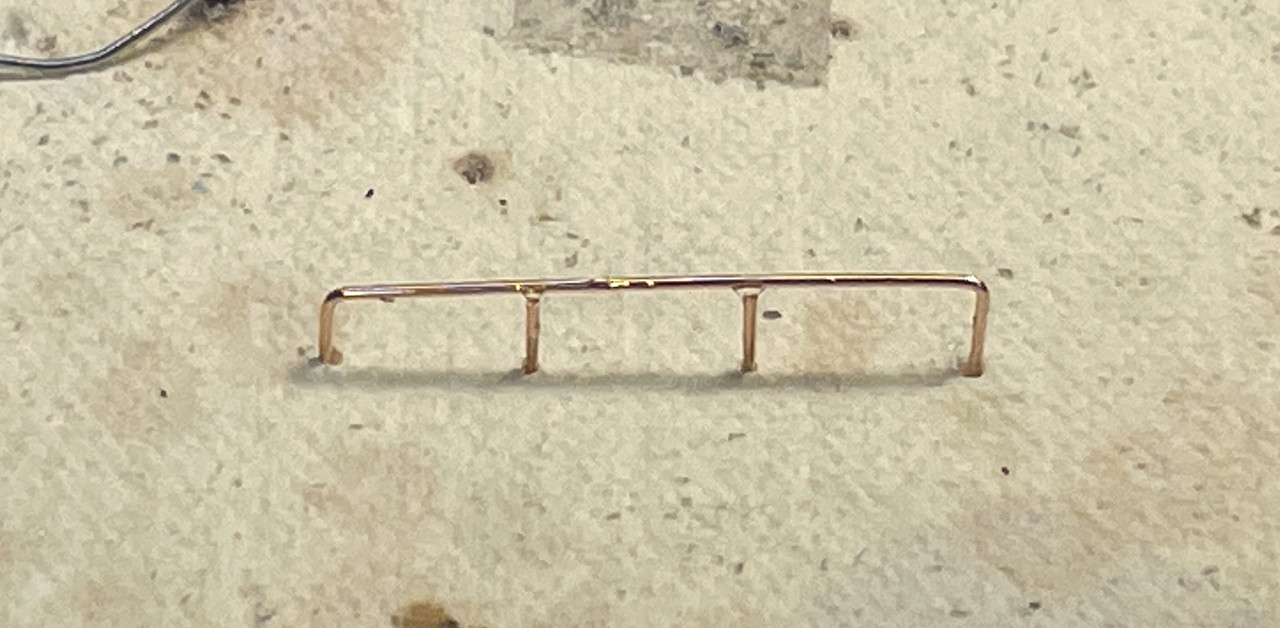
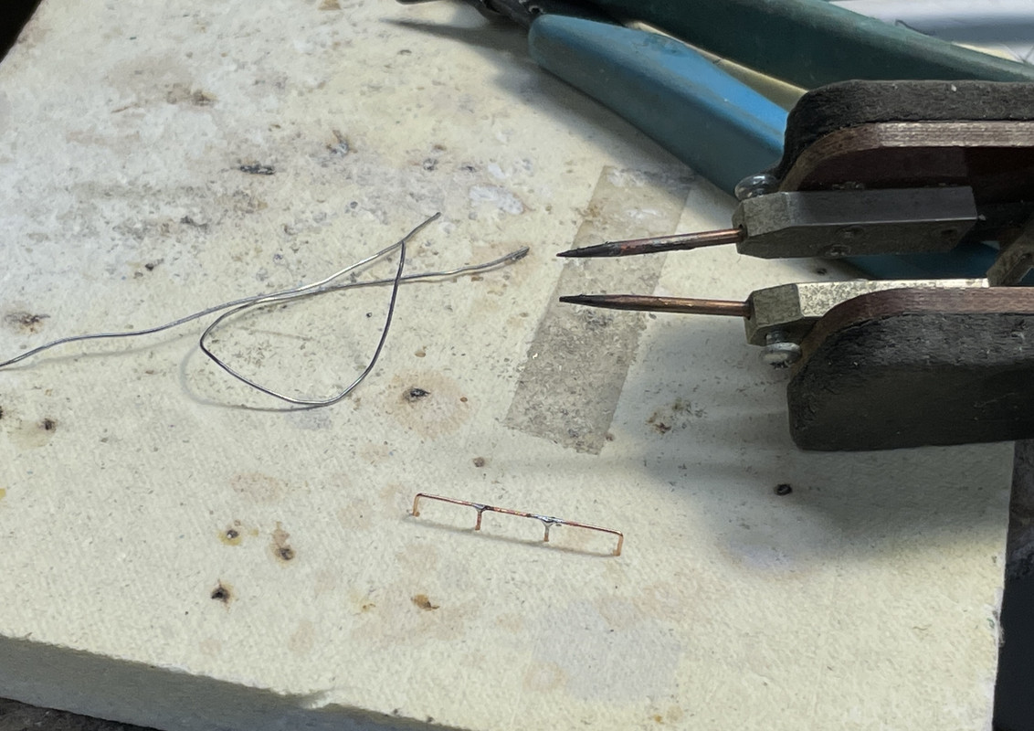
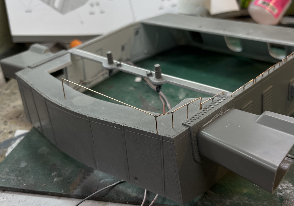
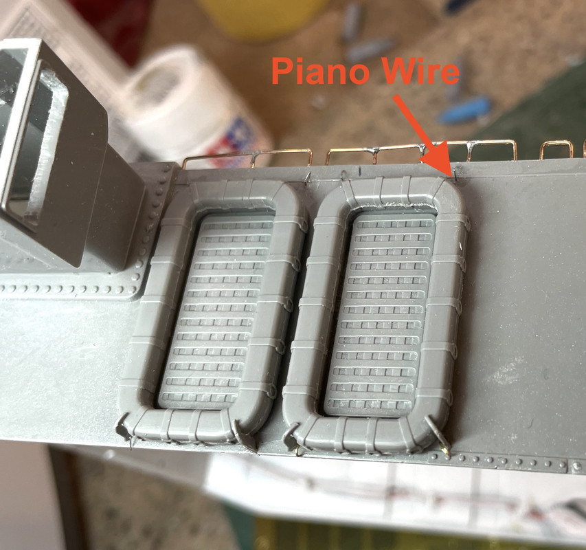
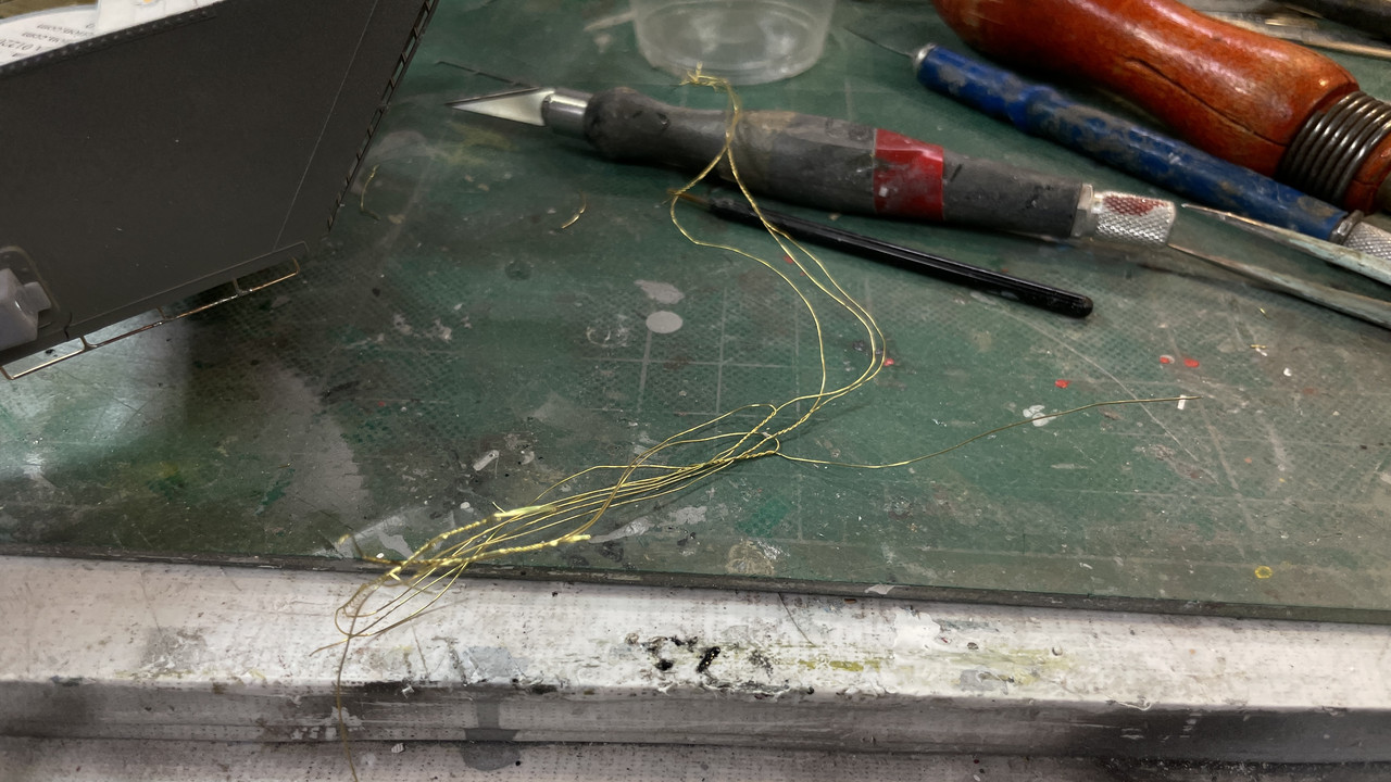
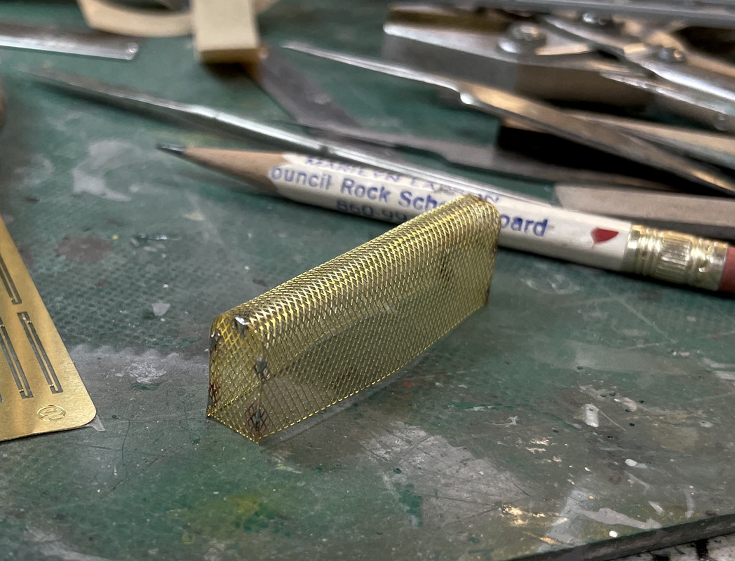
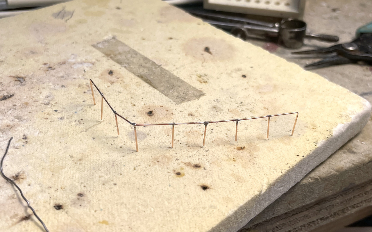
t is so fast and concentrated that I could solder the verticals with the metal supported in the hole in the gun house. Instead of filing the angle on the end, I filed a curved notch in the middle of the wire. The notch nestled tightly against the horizontal and soldering was very clean. Furthermore, it was already aligned with the hole in which it was going to end up.

After I took the above, I went back and filed the protrusion from the lap joint. The end result is pleasing.

With that challenging work out of the way, I was back to cementing some plastic parts together. That seems so pedestrian, but it was relaxing.

There are some fine PE strips that attach to a PE ring that criss-cross the rafts. I’m thinking of going to soldered wire or using E-Z Line. If I use the PE parts I’m going to solder that too. I’m not a big fan of CA’ing PE parts, especially if it’s going to sit in a museum for a long time.

Incidentally, I probably broke five 0.022" carbide drills doing the railings. At over a buck a piece, the drills cost more than the bronze wire. One broke when a bottom of dull coat fell of the little shelf on the right side of my work space and hit the table hard. And of course the Murphy’s Law corrolary, “Anything dropped will do the maximum amount of damage”, was at play and the bottle hit the sanding block from the precision sander and the drill was below and of course was broken. Another broke when the pin vise fell on the floor. And a few broke when actually drilling.

There’s one more dilemma I’m facing that’s causing me some critical ideating. I have to slip the three lead screws into their respective screw boxes while getting all the rest of the gun house stuff into the pan deck. And you can’t look down and see what’s going on as the view is blocked by the now-installed guns and the gun compartment rear assemblies. The only view will be through the pan deck cutaway. And to make matters worse, one of the internal partitions completely blocks the view of the farther-most screw box. I may enlarge the cutaway that bulkhead more so I can expose that screw box.

To solve this problem, my idea is to carefully drill the ends of the lead screws and add a longer wire… much longer. And I will drill the screw box hole deeper… much deeper. This will enable me to insert the wire into the hole long before I have to seat the gun house onto the pan deck. I would like the holes to pass all the way through the pan deck out out the other side so I could guide the wire from the outside. But I don’t believe I have a long enough small drill to do it. Anyhow, it’s the last big challenge facing me.

5 Likes

Today I got the raft strapping completed, the PE vent grills installed, the projectile crane arm installed, some odds and end plastic details and fabbed that final gun house bulkhead. I’ve decided that I’m definitely going to enlarge the pan deck far bulkhead so you can see more of the port gun’s screw box. That will help in getting the lead screws installed.

Before the straps I had to install some connection points. The model just has the PE somehow being fastened to the gun house sides, but I needed more since I was going the EZ-Line route. The only PE part I was going to use was the teeny-tiny central ring. The Takom PE sheet was protected by adhesive clear plastic on both sides. This was a good idea. I peeled the sheet back on the facing side, but left it on the back. When I cut these tiny rings they stayed attached to the backing sheet and really helped control them.

I erred at first using high E guitar string (piano wire) for the attachment points. This wire is really, really tough and can poke you too. I did 7 of the 16 attachments this way.

I got one raft strapped. The EZ-Line is actually Lycra elastic thread made of many strands of very fine gauge, and because of the very large surface area this presents, cures thin CA almost instantly. That’s a good thing. You just make a half hitch, pull the elastic tight to stretch it a bit at the knot and apply a small drop of CA. Wham! it’s cured forever.

There is this tiny ring that you have to thread on both the top and bottom strand. I installed the top strand first with the ring and fastened the line on both sides. I gave a modest amount of slack. Not much is needed because you want the line to stretch tight while being somewhat centered. EZ-Line is very forgiving.

It was at this point that I started using this.

This lovely brass wire comes from a braided decoration on a bottle of Montepulciano Di Bruzzo Italian red wine. It’s a perfect gauge for fine detailing and is about 0.010", same as the guitar string. I have a 0.012" carbide drill I used for all these tie points. Believe it or not, I didn’t break the drill after drilling 16 holes.

With the brass wire, I was able to push it through from the back, and bend the eye on the outside with a tweezers. Can’t do that with the piano wire… it’s too tough.

I did one eye on this side and then all the eyes on the opposite using brass. Much better.

I bent the wire over on the back side and used CA plus accelerator to control them.

Here’s the completed strapping on the piano wire side. This will all be painted so it won’t be so glaring.

When working with these tiny parts I use my parts catching cloth that’s stapled under the front edge of my work surface. This has saved me a lot of floor crawling and it caught this for me today… twice.

With the rafts done I added a series of plastic bolt strips that surround the entire turret deck seal area. There were six segments and the engineering was terrific since they fit absolutely perfectly. This is a WIP shot. It was fun assembly.

Next up was the PE vent grills. Two go onto the back along with some tiny handwheels for the hatches. Incidentally, the Big J curator doesn’t know what that left hand hatch goes to. The one of the right (it’s upside down) is the access hatch to the turret.

And the side vents. They’re at odd angles so you have to pay attention to the orientation. I use Gel CA to fasten PE. You can control the quantity, it stays put and then you cure it with a light touch of accelerator.

Since I had the turret interior on the bench I figured I better do that last bulkhead or I might forget it. Did it just like the smaller ones. It’s not painted. I’ll brush paint it tomorrow in place.

The floater net baskets are a flagile contruction of styrene ribs and PE grating. I have no doubt about being able to build it successful… I’ve built enough in 1:350, but I dread having to handle the gun house exterior when I’m doing final assembly. It has to be painted with the gun house. I may created some scale nets to go inside. I have some tulle that looks about the right hole size for the netting. I have to decide on how to make the floats. With that done, the gun house will be ready for paint and stack building can commence.

I also want to install a line switch in the base to control the lighting. Right now you’ll have to pull the plug to shut off the lights. I’m not happy with that. I have a a switch and I’ll have to do some surgery to enable the switch to be installed.

5 Likes

Wow…if this isn’t Ultimate Model-Making, hands-down the best project of 2022, I’m going to take up knitting.

4 Likes

Or maybe ultimate model destroying. It’s all how you look at it. Today was one of those days.

One of those days…

It was the best of times. It was the worst of times… to paraphrase Dickens.

I was able to successfully form and solder the floater net baskets.

To more easily form the shap of the large I made a buck with the correct profile. This idea came to me when I was on my way back from Costco. It made getting the right curvature with the flattened bottom much easier. I then used the same buck to hold the geometry when I soldered on the ends.

Here was the firsrt basket all soldered. CA wouldn’t hold this large piece that was under some spring tension. Solder in perfect in this case. BTW: for the soldering novices out there… Solder does not form a mechanical bond between substrates. It forms a metallugical bond. It why it’s some much stronger than most adhesives. The solder literally dissolves into the surfaces being soldered. It’s why a thin solder joint is stronger than a thick one. The solder itself is not that strong, but the intermetalic alloy created is.

Then the first challenge came. The plastic top frame doesn’t fit over the basket and not due to my soldering since the ends are inset into the sides. The sides themselves are slightly too long for the plastic. If I pressed the issue the piece would have broken. So I soldered some brass angle to the top edge. The loops that go on do fit.

This image shows the angle pieces I soldered and how tight the fit of the plastic frame is.

I set this aside for bit and went back to the main assembly. I painted the bracket I built yesterday, and looked at that bulkhead that was hiding the screw box. It was not eligable for further cutting. I bit the bullet and decided to see if I could get the lead screws into their respetive screw boxes without modifying anything. And lo and behold, I was able to get the port gun’s screw seat into the screw box and get the whole gun house on top of the pan deck. I was also able to get the center and strbd guns’ screws in too. Eureka!.

But the decks weren’t meshing sufficiently. After evaluation, I found that the projectile hoist chases were too tall by about 1/8". Took it apart, cut off the excess and tried the fit again. Again I got the port gun’s screw in, but broke both center and strbrd screws at their hinge points in the gun slides. That wasn’t too bad since the guns don’t move and I just glued them into the screw box and positioned pointing in the right direction.\

The gun house DID fit to the right depth. I injected epoxy around the perimeter and let it cure. Then all heck broke loose. I went to elevate the port gun more and heard a “crack”! Uh oh… what broke. This is what broke.

Notice that the center gun’s screw is missing also. At first I just got depressed. Then my creative problem solving brain kicked it. I thought of doing what they do when replacing a nuclear reactor in an aircraft carrier… They cut big holes in all the decks above the reactor, take it out and weld everything together. I could cut the back open, fix the gun and glue it all back together. Drastic! I know.

But after dinner and some less panicked thinking, I realized that neither the trunnion caps nor the trunnion shafts are glued in. I should be able to remove the guns entirely, put in brand new screws and put them back one at a time and get the screws in correctly.

I can do this two ways: If possible I can bend the gun house partitions off of the trunnions and remove the caps and guns. If that doesn’t work or looks like I’m going to do more damage, I can extract the trunnion pins starting with the outer guns and move the center pins into the side trunnions. That may be the best approch. Meanwhile I need to print some more gun lead screws with the load-position guns’ a bit longer since they were just barely entering the screw box. And I will not post-cure them so much to leave them a little more flexible.

Oh… and one more thing… the port side long PE grill that I installed yesterday, popped off with an audible “Click” and disappeared. Yes, you read that right. It simply disappeared. I have swepted, cleaned and moved everything within a 5 foot radius and nada, bubkis, nothing. Gone!! I fully expected it to fall out of my shirt when I changed out of my shop clothes into my decent-for-dinner clothes, but nothing fell out. I’m sure I will find it. If not, I’m not sure what I’m going to do. I could print something or make something out of bridal tulle, or perhaps it will pop out of the dimensional rift that it popped into and show up tomorrow. You never know. I don’t have the time to order replacement from Takom and making my own PE is the one special technique I can’t do…yet.

Another day, mores problems to solve. I was worried about installing these screws and my worries were realized. But, it will be fixed. Man… I’m glad I didn’t glue in those trunnions.

4 Likes

Scary stuff, glad you’re keeping calm & carrying on. While the carpet monster may be the culprit re the PE grill there may be an alternate. A few years ago I’d just put a dab of cyano on a PE clamp, using the tip of a blade to force it into its recess. Ping. I’d blinked so had no idea where it went, like you searching everywhere without success. That night brushing my teeth, looked in the mirror because something was glinting on top of my ear…

2 Likes

Yes… Perserverence is the key.

Another dramatic save in the making. Not gluing the trunion pins saved my cookies. I was able to extracate the port gun by pulling its pin completely out, and the sliding the center gun’s over to the port trunnions and freeing it also. This enabled me to remove the broken elevator lead screws to install new ones.

Speaking of new ones, in a few minutes on SketchUp and an hour+ on the printer I made a gaggle of new ones in three lengths. I made a lot and only post-cured them for 8 minutes. They bend but don’t break. And I bent a couple like a pretzel in figuring out how to get them in properly.

The center screw broke at the screw box, and I HAD CA’d THE SCREW INTO IT AFTER THE TOP END HAD BROKEN YESTERDAY. So there was no way of getting that chunk out. I was able to drill it will the Dremel Flexi-shaft handpiece with a 0.033" carbide drill. The hand piece just fit between the bulkheads letting me get down the pan deck’s floor. The drill broke just as a I was finishing up, but the broken piece was sticking out of the screw box. I was able to remove it leaving the hole intact.

This bird’s eye view shows both the port and center screw boxes. The port side (B) is intact with its original opening. The center one (A) has the small 0.032" hole for the pinned screw. While I now can individually insert each gun’s screw without worying about getting all three in at the same time while holding the heavy and delicate entire gun house assembly. That brass strip sticking up vertically is going to be the fish to pull the gun house shell wiring into the guts of the build.

I almost had another catastrophe (averted) when trial fitting the center gun when I had put it in ON TOP of the open spanning tray when it’s supposed to enter the breach. I was meeting some resistance, and thankfully, didn’t force anything. I was pressing down on this very delicate structure. I caught myself and did not break it. You get lucky sometimes… and frankly I was due. When they say, “hey it’s not brain surgery!” I say, “It’s really beginning to feel like brain surgery!”

I was also able to pull the upper pins holding the stubs of the broken screws and release the stubs.

And install the new screws. The center gun’s is truncated and has the 0.032" phos-bronze wire that will be joined into the screw box. Before painting the screws I did test fits to see if I could now steer the srews into their respective openings. I was able to successfully do this. (except for that almost-breaking-the-cradle caveat). I then painted the screws the Alclad aluminum, Tamiya black panel accent color and finally some AK Interactive Real Metal wax-based buffing color. I also had to reglue the gun captain’s platform which had broken some time ago and was pinned and CA’d. it broke again when I was trying to fit the scew into the socket. This time I epoxied it and it’s fully curing for tomorrow’s reassembly session.

I finished the floater net baskets. I used three out of four plastic end frames. The fourth fractured and was not savable. How you are expected to put these parts on a large PE structure that just CA’d is beyond me. Soldering was a much more effective way to construct this.

I used some 0.010" X .040" styrene strip to make the fourth end. It’s slightly different…

The instructions showing there mounting rings added to the basket and then gluing to the turret. That might work if the rings were being glued to the kit’s upper styrene frame. Since I was not using that, I had no way to correctly space them. Examining that drawing, do you see how hard it would be to CA that end PE to the body PE with now flanges?

Instead, I glued the supports to the turret first and then dropped the basket into the loops and CA’d it from the insides. This worked quite well. The molded-in ribs gave perfect alignment guides.

Here’s the first basket in place.

And the second one.

I did some reseach on how to construct 1/72nd floater nets to populate the baskets, but came up pretty empty. While I can understand the floats themselves, I was unable to get any details on how they’re strung together. It’s not a show stopper and I’m really running out of time. If I have find some time, I’ll see what I can do. However, making some crew members is more important.

The gun house is now ready for paint! I have to prepare the masking for both the shell and turret base and then reinstall the guns. I was unable to find that piece of PE even searching a wider area. Nothing. I’m going to fab and new one out of a perfect bridal tulle. In fact, it might be better than the PE it’s replacing.

So sports fans, I’m dodging another bullet. I don’t have a lot of time left and can’t keep fixing crap that I shouldn’t be breaking. Being able to remove the guns without further damage was very lucky! Hopefully I won’t have to press my luck any more.

7 Likes

Finally, a day where all arrows pointed in the forward direction. I got all three elevation screws corrected, installed and broke nothing new. I replaced all the side PE vents with tulle. I masked and painted a coat of haze gray on the upper works, and I did some final touch up on the projectile flats and added ammunition to all the projectile decks for the final assembly.

After finally fixing the port and center gun’s elevating screws, i pulled the trunnion pin on the strbd gun and replaced its broken screw also. I thought that just having the stub pointing in sort-of the right direction would work, but had second thoughts and fixed it right. I drilled out the old piece of screw in the screw box and was able to actually slide the new screw into the screw box.

So now all three are correct and I could put the turret shell on for painting. While it was difficult to work within the confines of the pan deck, it wasn’t impossible and, using a long tweezers was able to maneuver the screws into position WITHOUT damaging the delicate cradle assemblies.

In handling the whole deal, I broke out the remaining side PE grills and again lost the long one. I used the bridal tulle to replace the side vents on both sides. I may go back and add some framing to these to finish them better.

I masked the insides from the outsides from inside covering most of the area with paper on which I first traced the opening.

Oh… and I used that brass strip to fish the turret shell’s LED wiring down below with the wiring from underneath the gun girder. So all the wiring is staged to go down lower.

I completely masked the pan and electric decks. I also carefully removed any excess epoxy scraping with a single-edge razor blade. I will touch up the white…again… since it has gotten a bit distressed.

I added the metal guns passing them through the bloomers. Neither are glued yet especially since the bloomers need to be painted a weathered rubber color. But I needed to put the guns somewhere to paint them.

I used Badger Model Tech acrylic Haze Gray because I’m basically lazy. It’s a decent paint, and the bottles screw directly onto my Badger XF-150 air brush. The labeling said, Haze Gray (early WW2), and I think it’s too dark. I have Life Color Haze Gray that I used for my WW2 Missouri build which is a lighter shade and I think I will shoot it again with that color.

It looks so much better with paint.

Here’s the tulle grills with paint on them. The turret shell is not fully down into its final position. When it is it covers the sort of ragged top edge of the tulle.

Here’s a staged shot of the turret with my iPhone on a tripod and triggered with my iWatch and me holding up some additional lighting. I painted the range finder end caps seperately and will glue them in when the range finder optics are installed. I still have to paint the optical windows on these parts.

With paint going on it really feels like this thing is finally coming together.

I added projectiles to the inner and outer rings on the projectile decks and I changed the color of the gypsy heads so they are polished steel with a tiny bit of brass showing at the bottom.

I have just the clips and buffers to add and that gets done when the stack is built and I can get an accurate location for them. The sit just below the ring gear. The buffer and clips go on the electric deck shell, and the stops go on the outer shell wall 180 degrees around from the buffers.

Final assembly will start in a day or so.

6 Likes