Fantastic work! Have you ever taken the Firepower tour on the New Jersey? I got a good close-up of these types of guns when I visited the USS North Carolina a few years back; the NC had 15 inch guns vice the 16 inch of the Iowa class.
I did get into the turrets a few times, but not to the degree that I’m going to have to in order to make this project. The USS NJ curator has offered me a tour that will get me into those spaces. I’ve seen the Big J 3 times, the Alabama with its 16"/45 cal guns and the USS Arizona with it’s guns.
1 Like
BTW - bit of trivia, BB55 NC has 16’s, they’re L45’s with the shorter barrel than that the Iowa class’s 16 L50’s.
1 Like
All the more impressive by doing this in SketchUp. As much as I like the program, complex assemblies like this would leave me very frustrated.
Look forward to seeing more
Thanks Guys! Yes! SketchUp is a difficult program to work with mechanical things especially if you don’t have dimensioned drawing from which to draw.
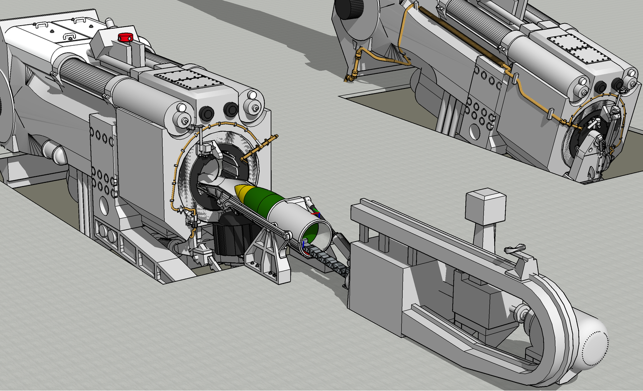
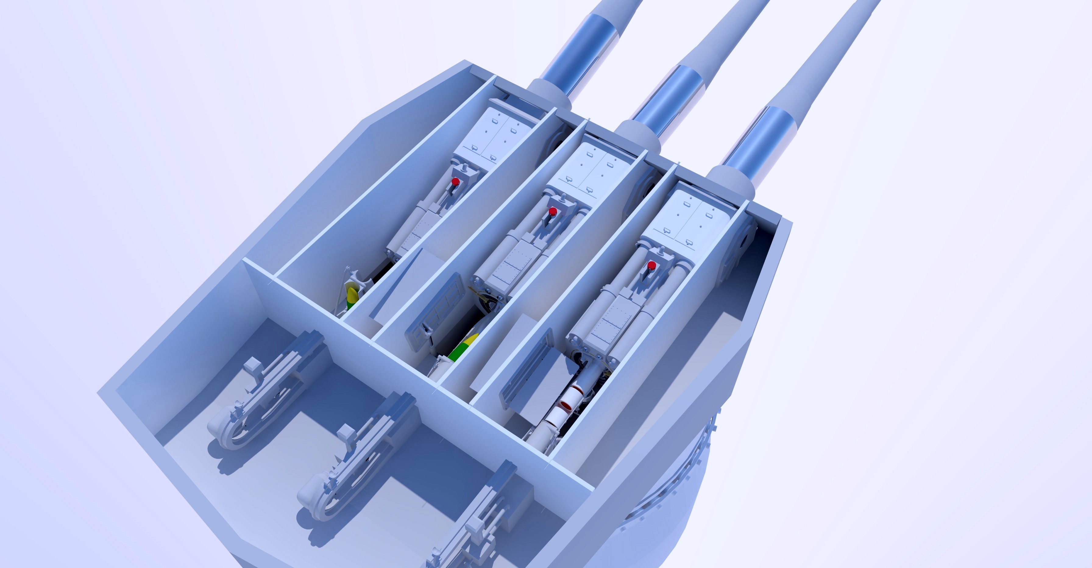
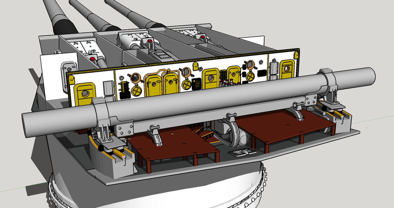
Drawing continues feverishly. I finished detailing the major components of the gun loading system in the gun house itself. This includes the rammer machinery which exists in the officers’ compartment at the rear and the cradle and spaning tray. The latter captures the 16" projectile coming up from the projectile hoist, rotates it to the loading angle of 5°, and with the cradle and spanning tray provides a smooth surface to slide the projectile and the 6 powder bags that follow into the gun’s receiver.
Drawing the cradle involved all of my SU skills and a new extension, “Truebend”. TrueBend enabled me to wrap the rib pattern around the barrels of the cradle and spanning tray. There were a lot of mechanical relationships that had to be figured so the cradle would fold in the proper way. At 1/72, I’ll be lucky if it prints at all let alone actually articulate, but I wanted it to be mechanically accurate.
This is the loading position. Remember: there will be bulkheads on all sides of the guns separating them from each other and the officers’ space. The rammer machinery is outside of the gun chamber with the rammer chain going through the wall.
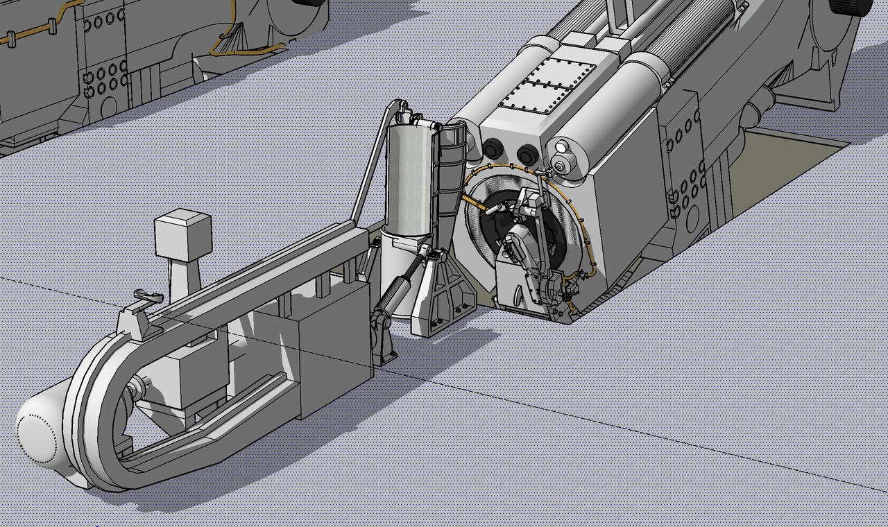
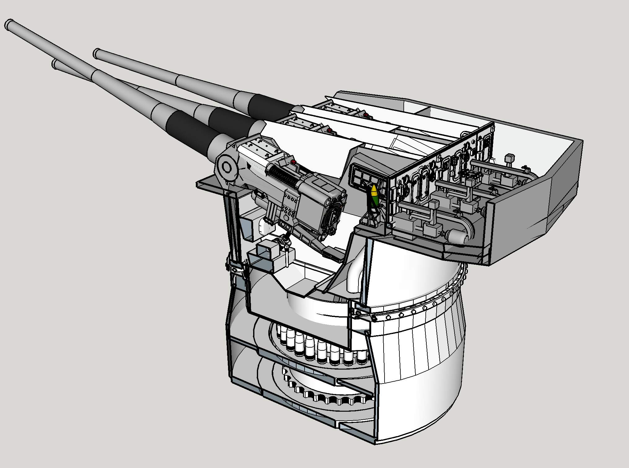
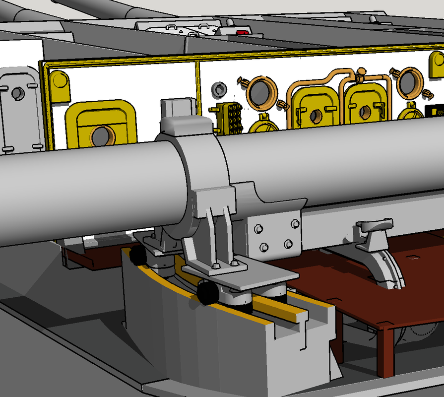
Here’s the firing position.
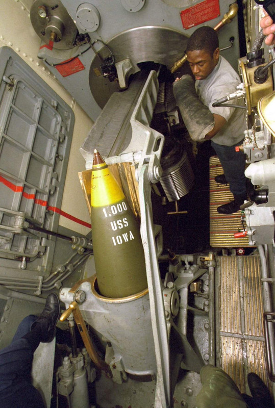
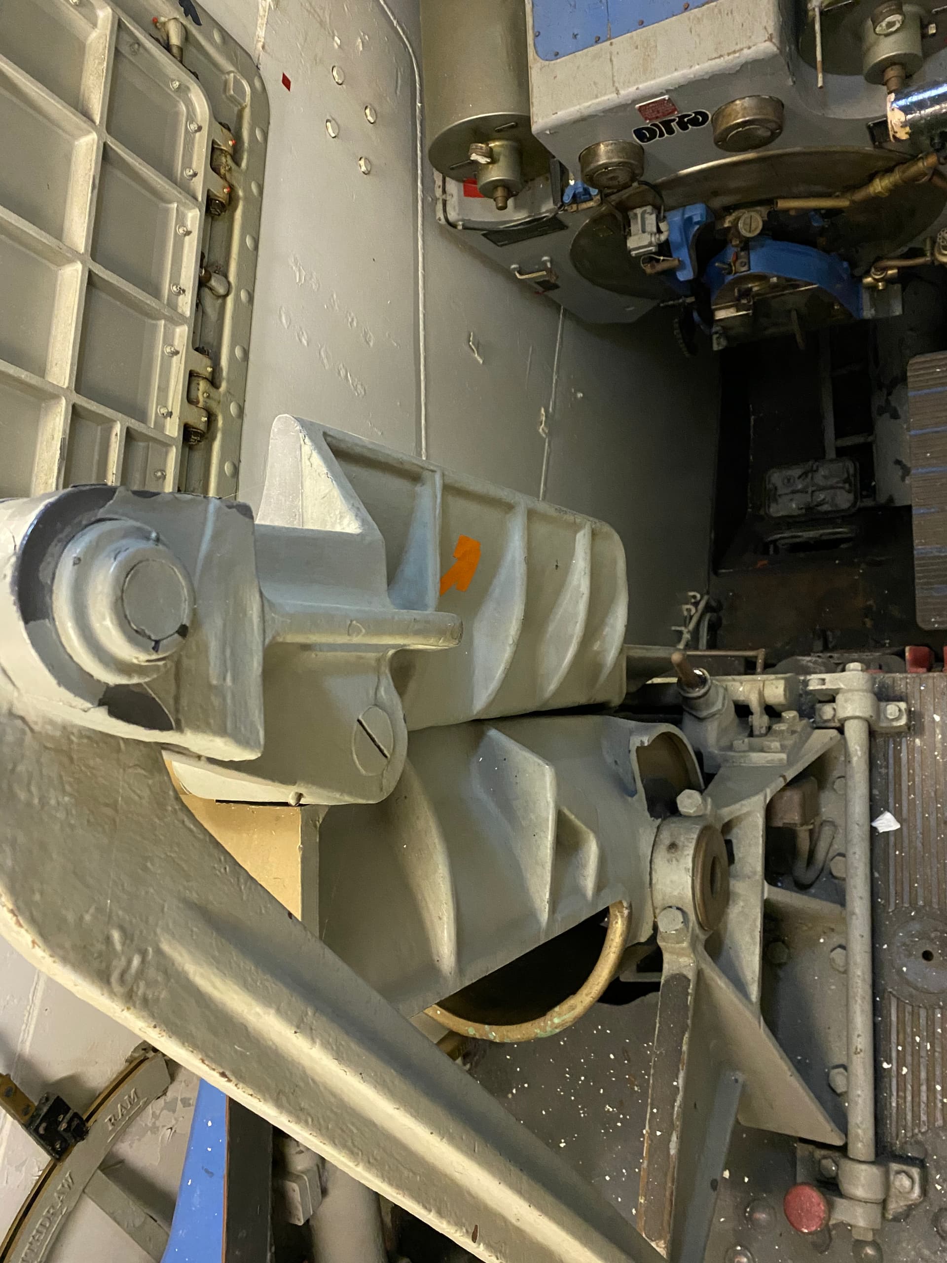
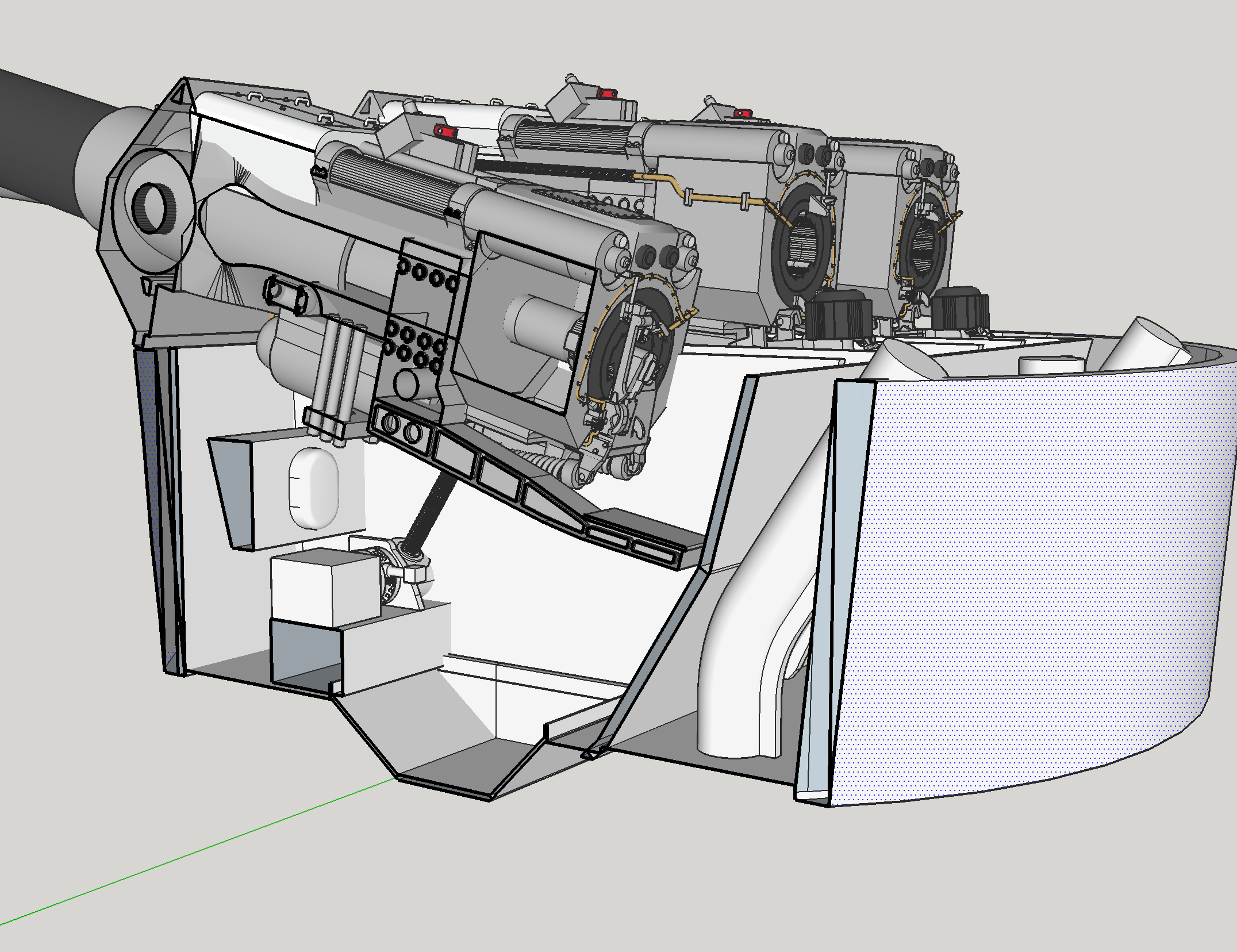
The singluarly most difficult part of this whole part of the project was figuring out just what was happening with the spanning tray control link and how it attaches to the tray. I had one picture on which to rely and it was ambiguous. My first attempt was completely wrong. The arm had to be far enough away from the unit to clear the main pivot bearing, but I couldn’t quite understand just what was happening. This link bends the spanning tray to horizontal when the cradle is lowered and bends it to lock position when the cradle is raised.
The part in question is the light color shape next to the gun captain’s elbow. It looks like it’s sticking straight out from the tray, but its actually first dropping down and then projecting outward. Because the tray is angled in the process of flattening out, you’re looking as much at its end as it’s top. The big hinge is at the bottom of the spanning tray. Because of all this angularity and perspective I wasn’t able to trace the shape as I do with other objects.
Here’s a view of what I drew. It’s still not perfect, but I’m not sure how to make it better with just his one image.
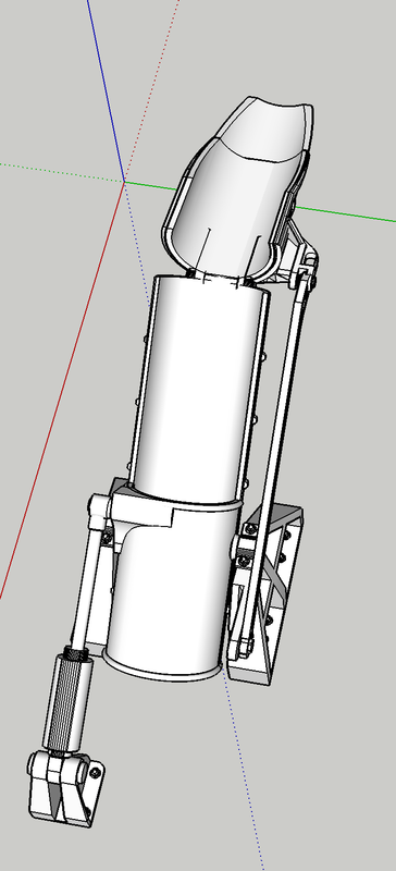
The real question I have is just what will print successfully at 1/72nd? A lot of the details I’ve drawn may not reproduce such as the hex-headed bolts.
5 Likes
Wow ! Really coming along nicely. If I understand correctly, you’re having trouble with what I would call a horn on front of the second tray segment ? These photos may help
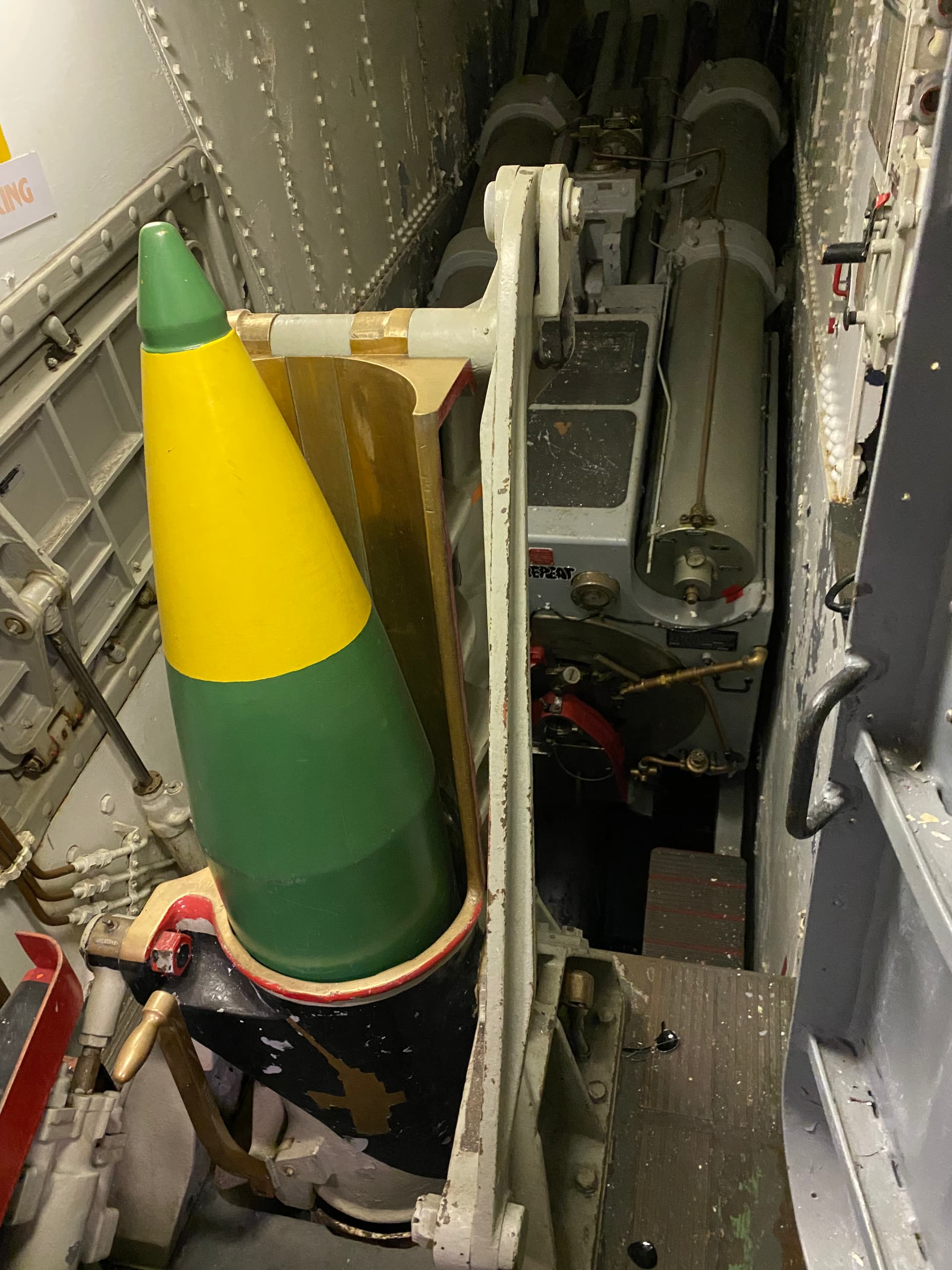
2 Likes
That is EXACTLY the part in question and you images really help. It’s offset toward the cradle are critical to get the connecting link the right length and it side offset to clear the base. I will incorporate this new Information and redraw it… again.
I think I’ve got it as best as I can. I’m calling this done. Again, thanks for those images that really helped me!

3 Likes
My pleasure, I look forward to seeing it in person when it goes on display in the ship.
Some great CAD modelling here. The level of detail is really impressive. ![]()
Just think, back in the day, every single component had to have its own detailed technical drawing done, all hand drawn, so that it could be passed onto the suppliers to manufacture each component ready for assembly. Much respect for those teams of hundreds of draftsmen and the amazing work they did! ![]()
As for printing the parts, what medium are you planning on printing them in? If you’re planning to print in resin (EG SLA) then the level of detail should be fine. Have a look at @Model_Monkey Stephen’s amazing website and what level of detail he’s able to achieve in his printing… Alternatively Micro Master are achieving similarly impressive results… ![]()
3 Likes
I print with an 80/20 mixture of Elegoo ABS-Like UV Resin and Siraya “Tenacious”. Tenacious is a fully flexible resin that when mixed with the Elegoo imparts a lot of impact resistance while still duplicating all the fine details. I print at 3.5 to 4.0 micron layer thickness. I’m doing this on a 1st generation Elegoo Mars LCD Matrix printer. It has a relatively small build area, but it does do some miraculous stuff.
I’ve finished the detailing of the gun loading equipment and started working on the bulkheads and other machinery in the gun house itself. I was able to do a pretty close job on the powder doors after finding another good diagram. Here’s some status shots. Remember, the turret walls will be from the kit.


And a rendering of same…

I have to figure as I go on just what walls will be cutaway, or transparent to show all the cool stuff that going on inside. For example the machinery that runs the powder hoist is an elaborate electric driven A end/B end hydraulic hoist system that’s located on the gun house floors between the bulkheads behind in front of the powder hoist chase. In fact, almost all the systems that run the turret are similar electro-hydraulic system with a motor-pump and remote actuator. This includes the traverse, elevation, and all the various hoists. I plan on detailing as many as I can.
8 Likes
I recall my father speaking of synchronous motors as part of the gun laying system . One motor connected to the gun’s elevation system and it’s partner connected to a pendulum so the elevation relative to the horizon stayed constant regardless of the ship rolling.
Was there an such system for azimuth/traverse ?
Some of you artillery guys may be able to enlighten me .
1 Like
If I’m not mistaken, the synchros drove the five inch and 40mm guns. The big guns had electro-hydraulic systems that were also part of a servo system. With the moving part of the turret weighing 2,600 tons and the guns themselves at 150 tons, they needed amplification to make things move. That said, the gun was carefully balanced around the trunion and wouldn’t take too my torque to move it. But, it would take power to stop it from moving.
The gun laying could be done from many places in the ship starting with the main directors at the tower tops, then the long span range finders in the officers’ compartment and finally, individual pointer and trainer stations on the open spaces in the turret flanks. Add to that, each location had the power to fire guns from all the other positions. The ship was designed to fight and multiple redundancies to ensure it could regardless of the damage to one or more systems.
2 Likes
More progress on Missouri Turret interior.
Working on the pan deck after detailing the ofc’s compartment bulkhead. I have to constantly remind myself that the ultimate model will be 1:72. That means the entire bulkhead is only a little over 5" wide. That’s small, but there’s a bright side; I can print the entire bulkhead in one piece. I’ve delineated the elevating gear and am thinking about how to make the guns movable, but that may not be necessary since the model is going to be under cover. I still have some geometry issues. For example: the port side guns shield is hitting the wall of the Pan Deck. I don’t want to move the guns so I may have to make the pan deck slightly larger in diameter. There are some errors that need correcting like the lack of thickness of the pan deck floor. It should be as thick as the lip rising up from the Breech Clearance Pan at the bottom.
The guns elevator by way of a large lead screw surrounded by a hydraulically driven rotating nut. The gun turret traverses by another hydraulically operated motor turning huge pinion gear engaged with a ring gear that surrounds the entire pan deck. I’ve yet to draw either gear and many need help drawing the ring gear. There are two pinions sets driving rotation. All of this hydraulic stuff is there so there’s no chance for an electrical spark anywhere near the gun floor. The pumps and electric motors providing the hydraulic impetus is one deck below on the electric deck. That’s the next drawing challenge.

There’s the giant optical rangefinder and the manual aiming stations that need creating in the gun house.
Still have a lot of drawing to do and still waiting for the kit and metal gun barrels to arrive at the hobby shop.
13 Likes
can’t wait to see this when it takes physical form! 
Neither can I. I’m still waiting for the darn kit and guns to arrive at the hobby shop. It could be built without the kit at this point since I’m detailing so much of the stuff the kit has as well as all the stuff that isn’t. Today I finished up the traversing gear. This includes the B-end motor and gear boxes on the pan deck and the action ring and pinion gears protruding from the electric deck. My pinion and gear set has bigger teeth since it has to be able print in 1:72. And just for fun I figured out how to make rifling in the big guns.
Next up is a massive amount of equipment on the electric deck and finishing up the detailing the main gun houses. Interestingly, there was a manned station on the electric deck with a hand wheel a la those found on 40mm quad emplacements. These were manual stations to elevate the guns. There were three stations, one for each barrel. In the recent video “Raising the Iowa’s Guns”, the mechanics were using pipe wrenches on the shaft that goes to a bevel gear in the coupling between the elevating nut housing and the hydraulic motor. It was very slow going, but one deck below is the station with hand wheels to crank the guns up and down when the hydraulics were unavailable. It had to be a rough job to hold, sitting in a compartment with a load of electro/hydraulic machinery running and basically doing nothing unless something is not working.


5 Likes
Thanks for giving me yet another thing to distract me from my domestic duties…
Your CAD work alone is already monumental. Even if you were to never build it, this alone is exceptional work. I can’t wait until you start printing.
If you want another reference for the spanning tray, the video on the working of the 16"/50 Mark 7 gun at HD Stock Video Footage - Working of 16 inch 50 caliber Mark 7 gun as the main armament of BB-61 class battleship, United States. at about 3:00 into the video has some useful shots.
Thanks to all. I got some more images of the floor area in the officer’s compartment. It turns out that the reason it was ambiguous (to me) was the flooring plates are removable so they can get to the buried ramming machinery. It was the buried rammers that didn’t make any sense to me. The floor is supported on some legs and trusses. It’s pretty deep and it has four steps to get to the operating level. Here’s how I interpret it.
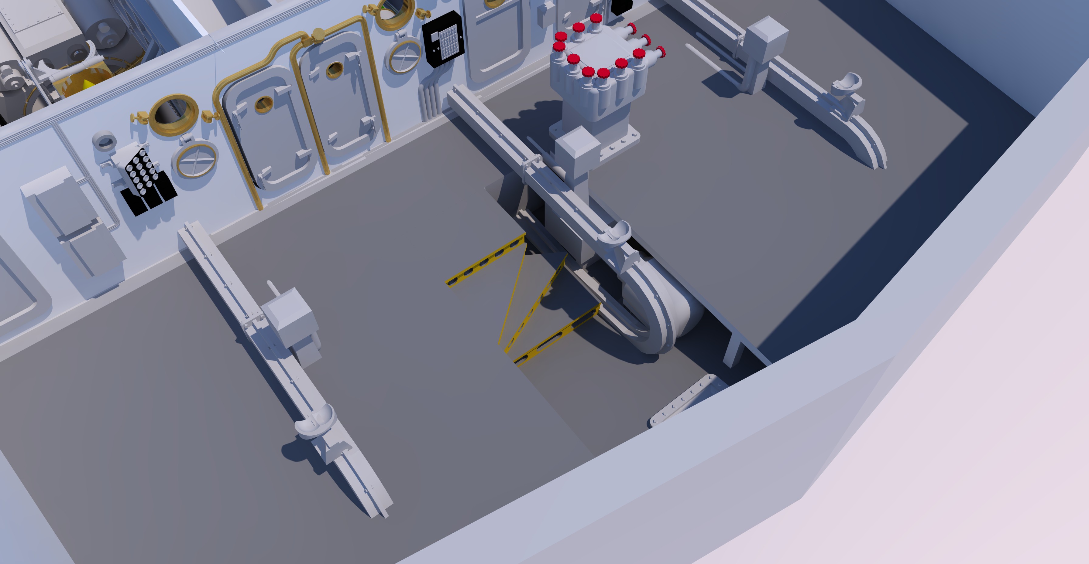
While there is more and more wiring and piping that can be added, I have to keep in mind that we’re printing in 1:72. If it was 1:48 or 1:35, it would be a whole different deal.

Onward and upward.
6 Likes
I just spent two days building the support system for the massive range finder tube. My first attempts where what my mind’s eye “Thought” was the shape of the parts. I was completely off! I erased it all and went at it again. This time it’s pretty close. Having no real-world measurements or working drawings with dimension, the whole deal is a giant SWAG (simple wild ass guess). The support system is much more complex than I originally envisioned.
All the rolling surface are bronze or brass.
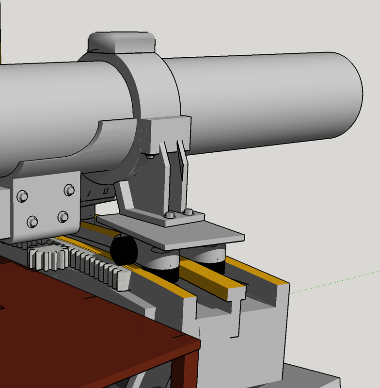
I’m getting pretty good at drawing sector and pinion gears. The gear teeth on the prototype are probably half the size and twice the tooth count, but I’m always thinking about what will reproduce in 1/72 on my 3D printer. I’m thinking of printing the enitre range finder in two parts mating in the center. All depends on how I can support the parts in the machine.
There’s still more to do on this part. I have to put in the three operating stations with their handwheels and optical sights. There needs to be a way to operate that pinion also. And then there’s the outer ends with the optics, weather seal and outer gates and their controls.
11 Likes