Feel better soon.
Thanks for the kind thoughts!
COVID update!
I had two days of low fever and yucky head, and the rest of the week was basically nothing. It’s lile the weakest head cold I’ve ever had. I took the full 40 pill dose of Mulnapivir, have no cough and basically no symptoms, but I’m still testing POSITIVE which means I’m still sleeping upstairs or hybrinating in the sun room binge watching all my stuff that my spouse doesn’t dig as much. Moral of the story: double-boosted people with COVID doesn’t get very sick.
7 Likes
Be aware that your meds and paxlovid have a substantial occurrence of rebound…ie getting covid again after an apparent recovery. It’s been theorized the medication course might be too short.
Feel better and make sure to get outside and get some fresh air!
1 Like
Just catching up on this thread. You work is simply astounding!
Hope you are feeling better soon. Look forward to seeing more.
Thanks for the kind thoughts. I did get a bit of rebound, although my case was so mild, I wish all my colds were this easy.
While I’m still testing positive (apparently that can go on for weeks), I have no symptoms, feel fine and in day 13. According to guidelines I can join civilized society, but should continue to mask when with others. I can live with that.
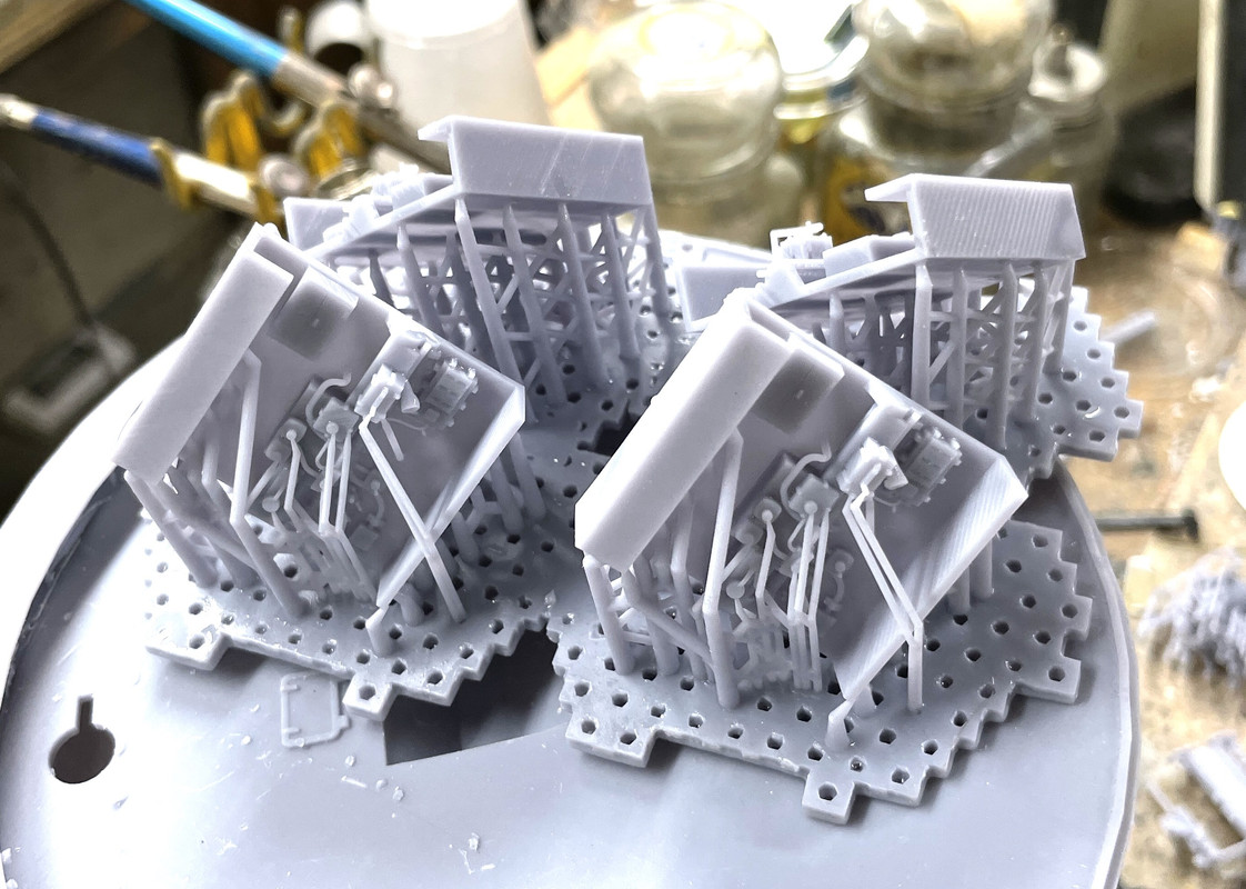
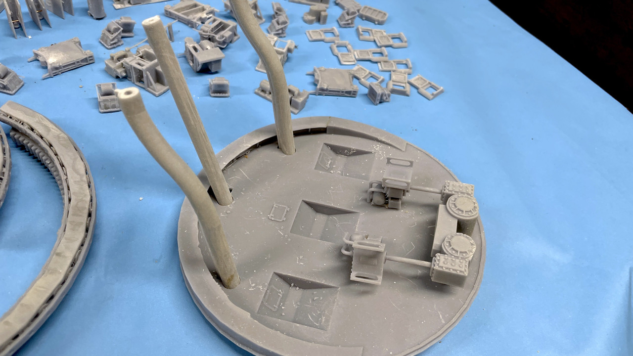
So I finally got back in the shop yesterday and printed some stuff. The air bottle print was mostly a failure. I didn’t have enough robust support at the base and some of the bottlws formed in the upper part of the print (which is unusual) while the part closest to the build plate was missing. I’ve reset the supports and will reprint the lot and get some more good ones. Only the ones on the foreground will be seen. Those on the shelf where it wraps around the back of the turret will be out of view.
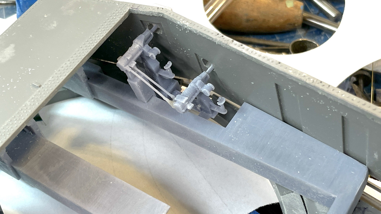
i got beautiful bolt detail on the reprints of the elevation gear tilting box. These are now very usable. This shows quite dramatically the differences in print quality based on where you put the supports. You are always balancing supports in the places to support a good print and keeping the away from details that will suffer from the support removal.
I also found that I was missing one of the B-ends and had too many of one hand and not enough of the other since the guns are both right and left handed driven by which side the powder trunk lies. So I’m reprinting some of these too.
Again, here’s a completed elevation system.
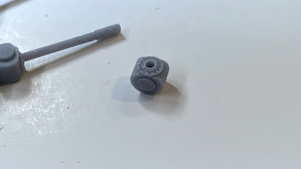
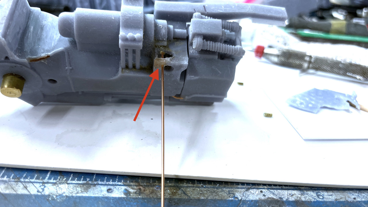
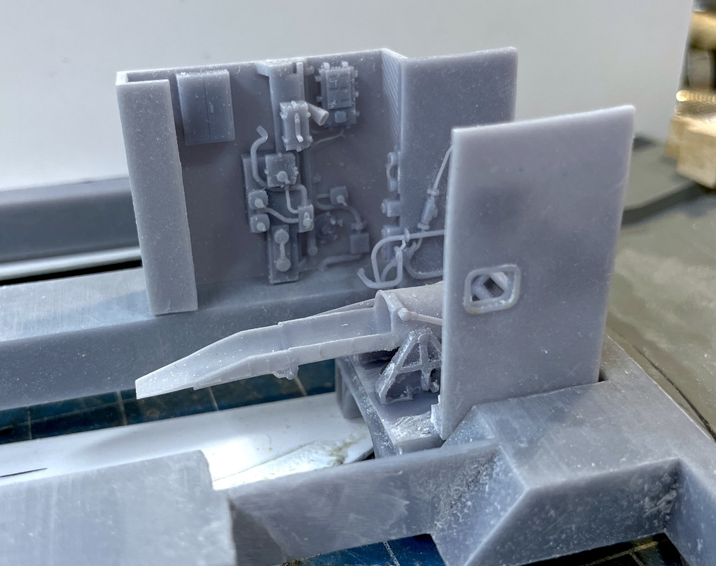
As for the other end… the connection between the elevating screw and the gun slide, I needed to come up with something that was both articulated and robust enough. I re-printed some of the screws to make the upper end a bit thicker to take up more space in the milled groove I made, and to add a little more mass into which I would drill the mounting pin hole.
I decided to install a piece of 1/16" brass tubing which has a 1/32" i.d… I epoxied (J-B Weld) this into the gun slide resin since the drilled holes weaken the walls significantly. I will then removed the tubing up the middle of the milled slot and insert the screw in the space created. I will use a 1/32" piece of Phos-bronze as the hinge pin. Unfortunately, the upper end of the screw is not wide enough to support the 1/16" brass tube and will be just holding the 1/32 wire. When I left them last night the J-B Weld was curing. I intially tried using Bondic, but it couldn’t handle the stress of the diamond burr I was attempting to use to remove the center brass section.
J-B Weld, for the uninitiated, is an epoxy that has metub and it’s my go-to cement when I really want to be sure about the joint’s integrity. I used it to hold piece of 0.010" piano wire struts to my Missouri and Essex antenna mast builds.
The screws will be attached to the guns first. The guns will be assembled to their trunnions while threading the screw bottom end into the tilting box. It will be a tricky assembly operation because you can’t reach into the pan deck when the guns are in place. I’ve been assembling this part in my mind and visualizing trouble. When I visualize trouble, it’s usually there.
I pulled a revised pan deck bottom plate off the printer this morning that was successful. This print is without the traverse gear, which I also successfully printed yesterday that will be installed as separate components. They weren’t forming correctly as integral parts of the pan deck plate. Sometimes trying to be too clever creates even more work.
I had my 77th birthday and don’t feel a day over 76. Oher than COVID, I’m holding up pretty well and my modeling has never been better.
5 Likes
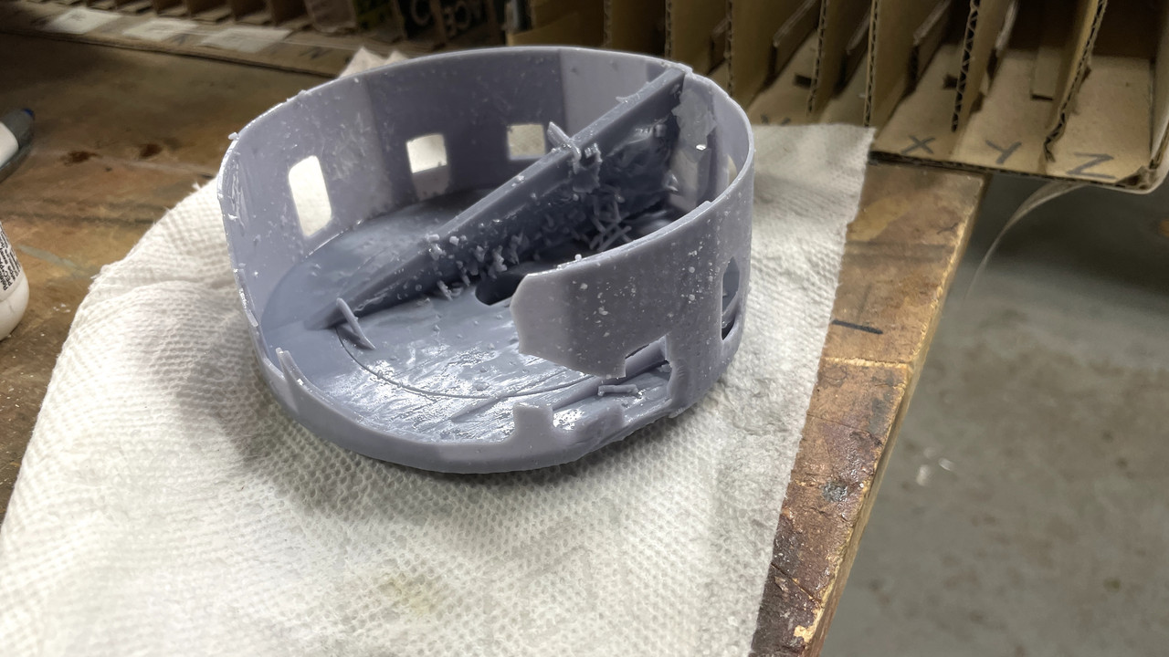
Short session… The powder flat print finished last night. The results are… perplexing. I thought I’ve had pretty much experienced every weird result in the technology, but clearly I was wrong. The powder flat printed in its entirety and then some. I’m very used to having parts of the job not printing or printing, but delaminating when a support lets go. This time the printer printed a whole bunch of stuff that wasn’t there. And I don’t know how this can happen. I don’t know what the mechanism is to create this.
Here was the original drawing. Notice there is no massive rib running down the middle.

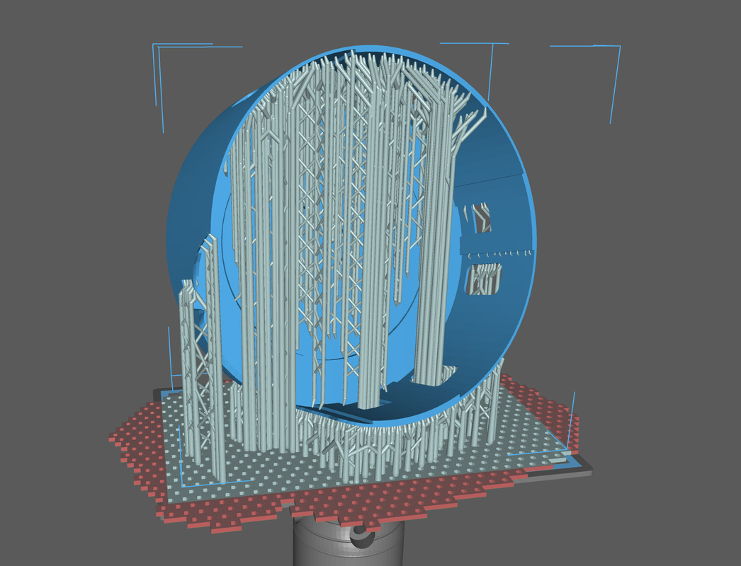
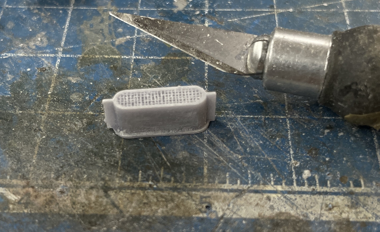
And here’s the setup on the printer. It’s a massive part and is simply the largest the printer can handle in the X-Y direction. There’s some more height possible. I printed with the open cutaway on the plate side. If I do reprint I will put the cutaway on the finishing side. All the red area is out of the print zone and will not print. As it was the Wham Bam spring build plate holds like crazy and the missing raft makes no difference in the outcome.
And here’s what happened. What the heck is that massive rib doing there? Where did it come from? Why is the top surface so regular? It’s almost like it was drawn that way, but I didn’t draw it.
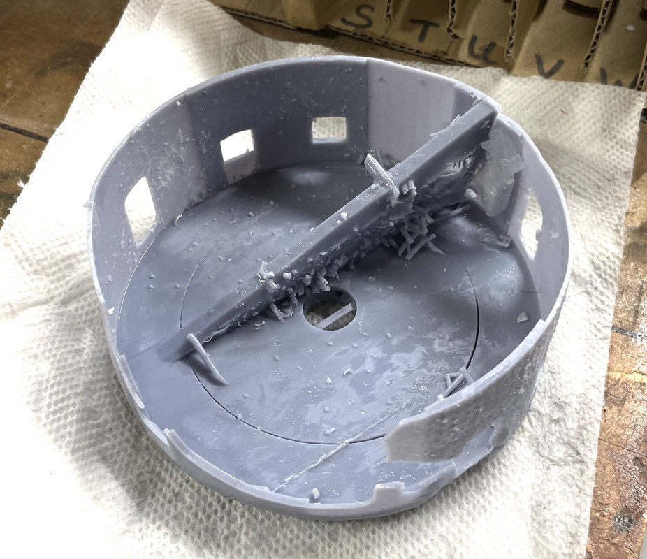
I can remove it with the Dremel and router so I can save the part. The part of the lower wall that broke out occured during support removal and I will just enlarge the cutaway area and, again, save the part. It used a ton of resin and took many hours and I’d rather not reprint if I don’t have to. On the printer right now is the revised electric deck and it too is a big complex part. I’m hoping that the creation of this artifact is not a technical failure occuring in the machine’s logic or in the LCD screen.
The other thing I did today was attempt to get those brass bushings fitted. The J-B Weld failed also when trying to remove the center section possibly from vibration and/or heat. In one case, I added thin CA and got it cut. In the second, the inner part remained and the outer part came out and was re-glued as above. On the third, the resin around the outer opening broke apart and failed. I was able to rebuild this with some phos-bronze pins and then layers of Bondic which I reshaped. I then drilled it directly for the 1/32" rod that will serve as the axle.
In my attempt to re-glue the outer brass pieces with thin CA, thee CA filled the hole. I was successfully able to drill the CA out with the 1/32" carbide drill. In the last one, the darn drill broke almost through the job and the carbide chunk is embedded. You can’t drill out carbide with carbide. I will have to remove the brass entirely and will probably have to rebuild the lug with pins and Bondic as I did before.
Using Bondic and pins is very similar to what dentists use to build up a broken tooth if you’re not getting a full crown. In fact, the resin’s almost the same stuff. That entire corner (arrow) was built up. You have to apply the Bondic is a series of layers curing each with the 405nm UV laser. When properly supported it’s as strong as the substrate.
5 Likes
I was able to surgically remove the “growth” that permeated the powder flat. There’s still more work to do to make the surfaces appear as if nothing was ever there, but I made a good start. I also cleaned up the cutaway some more, but more work needs to be done there too.

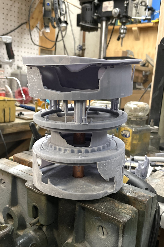
Just for fun I stacked up some of the completed decks to get an estimate of how big it’s going to be. It will be about 11" high depending on the attitude of the guns. I’m making the case interior one inch taller than the highest point. It will be dark in the shadow areas which is why the entire inside will be LED lit.
There’s an interesting product out there which uses an induction coil and little LED modules that pick up the induced current and wirelessly light the LEDs. I thought about using the method since wiring up the central column (very prototypical I might add) adds significant complication to the build. But the range is only 15 cm, and the closer you get to that number the dimmer the LEDs would be. It would cost about $70 USD, which isn’t a show stopper, but I was concerned about the light output. I don’t just want illuminated spots like lighting model headlights or running lights. I need LEDs that will produce lumens to light other surfaces. For that I will go with my standby LED surface mount units that produce gobs of light.
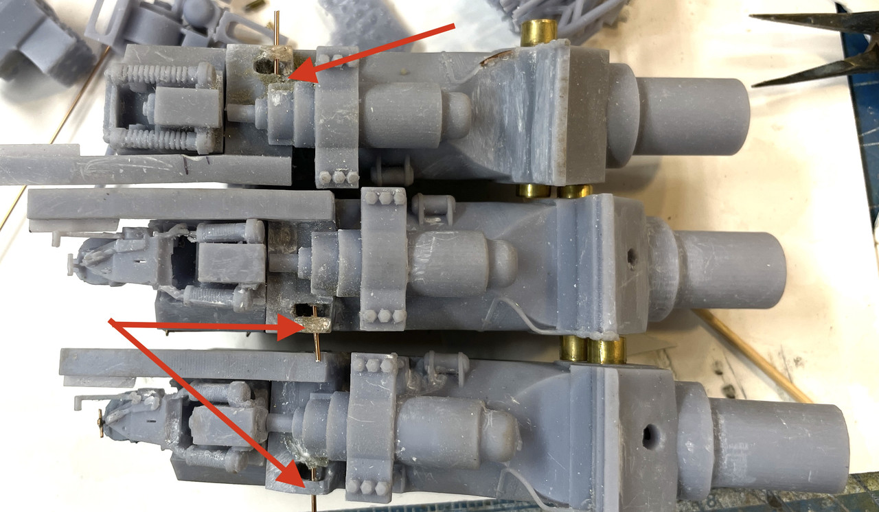
I finished up the addition of the elevating screws. I removed the brass with the broken carbide bit, did my Bondic magic and drilled it with the 1/32 bit. I also fixed another gun the same way and now have three guns with the lead screws attached. I’m going to paint them this way, although I thought about putting it togeher after painting the gun slide. I’m still open to people to sway me one way or the other.
Some pins aren’t exactly square but it makes absolutely no difference in how they’re going to be used. The only have to adjust once since the guns are at fixed positions.
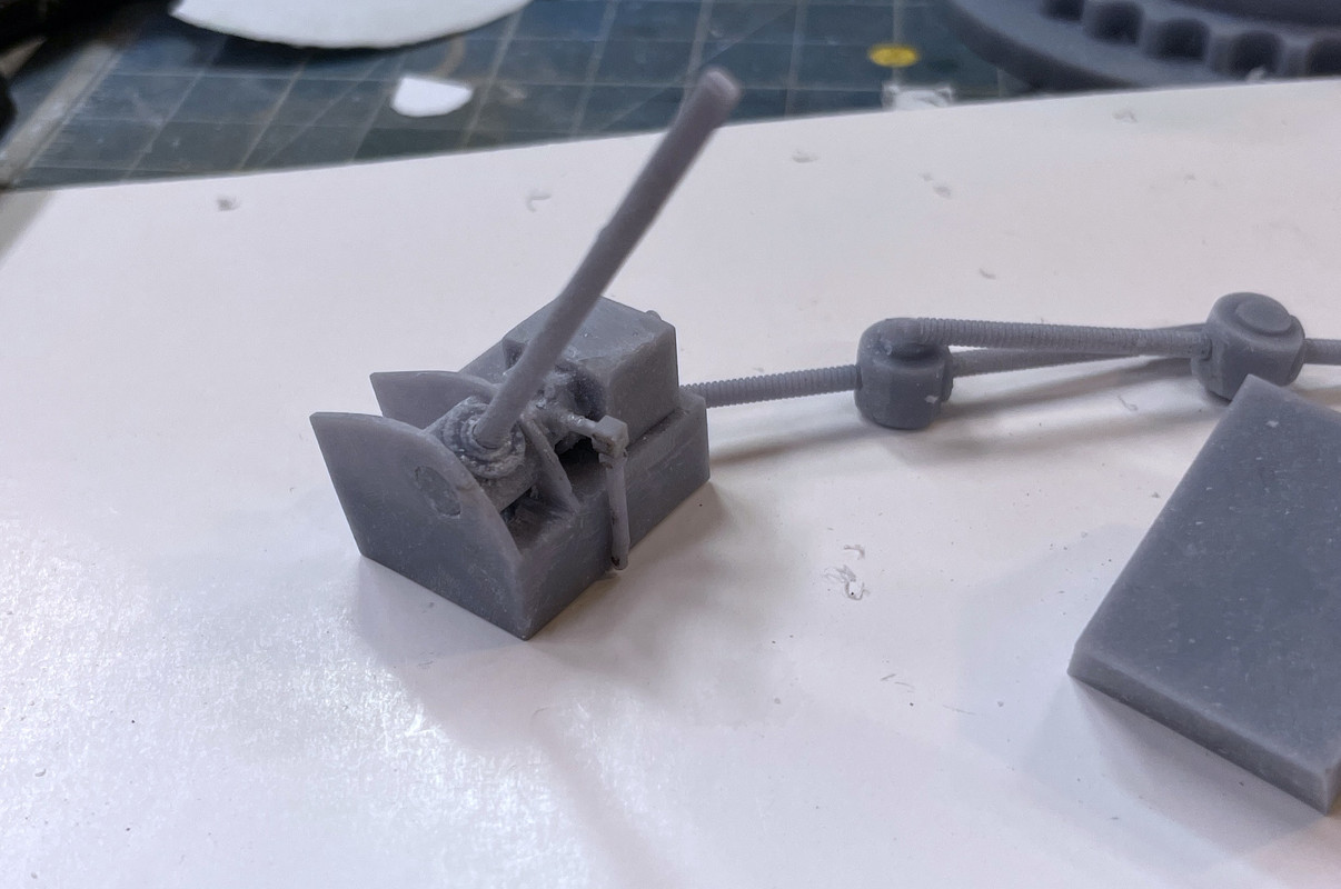
Here’s the first screw installed.

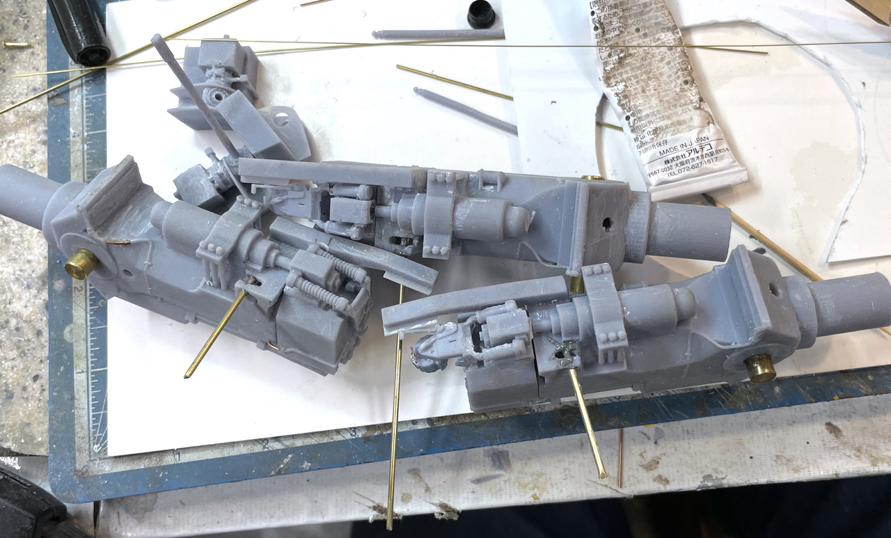
And here are the three guns. Notice the handedness of the three guns.

I believe that if I can estimate the correct angle of the tilting box, I can insert the screw into the box and then drop the gun into the trunnions. There will be limited access throught the cutaway. Then there are the partitions that will get inserted from the top of the gun girders and seated onto the pan deck floor. Once the partitions are in, none of the elevating gear will be accessible. I’m making at least the first two transparent so you’ll see into the pan deck interior through the partitions. Or at least that’s how I’m imagining it now.
The electric deck print was perfectly formed with no weird shapes. That elminates any systemic problems like the LCD failing. I can use this electric deck as is, but I think i’m going to reprint since it’s just using resin. I just ordered another kilo of gray and the Siraya Tenacious. The Tenacious lasts a long time since I’m only usng 15% per mix. The correct version (#3) has more partitiions and the floor openings closed.
6 Likes
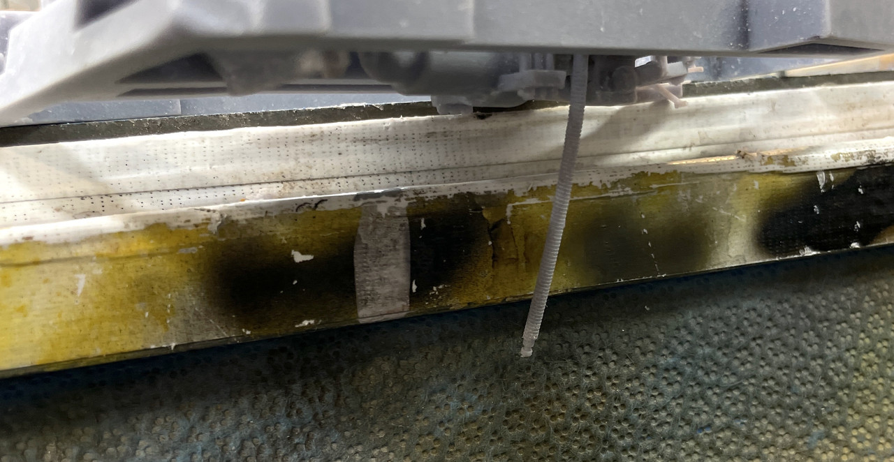
Found out yesterday, much to my consternation, that our four year-old GE dishwasher was leaking. Leaking in our house is a bad thing. First of all it damages the hardwood flooring under the dishwasher. And even worse, it leaks directly over my massive train layout in the basement. The basement ceiling is lined with Tyvek House Wrap that brightens up the space and prevents dust and spiders from landing on the trains. It also acts as a pretty good vapor barrier. This happened before, four years ago, and formed a huge, water-filled bulge right over my village. The Tyvek saved the railroad. It happened again!
This time it was the crappy plastic seal nuts that seal the entry points of the heating element leads. They were LOOSE! And leaking. The railroad got some damage since the Tyvek is not longer intact since we cut a small opening in it the last time to train the bulge into a storage container. This doesn’t make me happy. For a lousy $2.00 part, I almost lost irreplacable custom models and we had to go out and buy another dishwasher today. The seal nuts could be tightened, but I have zero confidence that they won’t loosen again and do more damage. We spent the afternoon at Lowe’s and this time bought a Bosch Model 500 dishwasher.
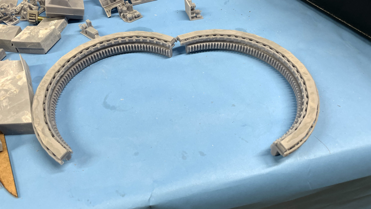
I’m regaling all this BS because I only had 15 minutes in the shop, but it was a good 15 minutes. I pulled this off the machine. The straight curve sides the result of using 24 segment circles to create it. I’ve upped that to 48 segments, but actually it should even higher to 96. Problem is that each increase in segment counts increase CPU time and causes latency in the system.
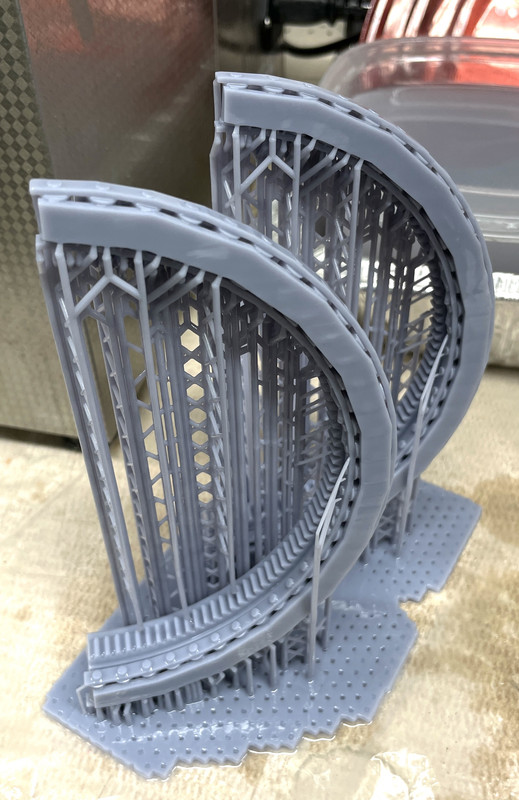
This is the redesigned split ring gear plus the roller bearing and both top and bottom races. Last time I did the ring gear in four segments because my Mars Classic 3D printer didn’t have the capacity to do it in halves. Furthermore, I was going to print the bearings as a separate part and it didn’t work out so well. With my split shell design, the ring gear was going to be in halves anyway, so why not print it that way. The print was PERFECT! I wasn’t sure if all the rollers would render properly, but apparently they did very well. Took a lot of support to insure good forming.
It’s now in the ultasound. The next job is already on the printer; the modified final version of the gun girders. I have very few prints left to make. That said, model building proper will commence sometime next week. The weather should be conducive to painting primer outdoors, and that’s a good thing. When it’s in the 90s, the spray is drying before it hits the surface and produces an awful finish.
I’m really looking forward to actually building this thing. I’m going to put together an image of all the parts laid out to illustrate how many parts it actually takes to build something as complex as this. Don’t expect Takom to do it any time soon.
4 Likes
Been in the building business my entire adult life and I am now 69 . You are fortunate that Tyvek saved your layout because it has a terrible reputation as a vapor barrier. Marketed by DuPont as a building paper when it was really developed for ripstop lightweight envelopes for military application.
Before you reinstall your new dishwasher have a pan made for the space under the counter- sheetmetal , fiberglass or rubber shower membrane and a drain in the pan to the waste lines or an emergency overflow.
I could type for hours about the things I have found when opening up structures that were “protected “ by Tyvek …. Sorry for the rant - touched a nerve .
I’m not going to go the pan route, but what I am going to do is put another layer of Tyvek with the side open over the aisle where the water, if there is any, will go where it will do no harm. The reason it leaked on the town this time was due to the slit we made in the Tyvek during the last leak to do a controlled release of the water trapped in a massive bulge directly over the town. The Tyvek was holding the water. We put a big tote on the layout in an open area and ran the water there, but I didn’t repair the slit and that’s where the water came from this time.
The dishwasher saga is now over. Between the initial leak and then the stop valve leaking after the plumbers left with the old one it was a real pain. The stop valve was one of those old multi-turn washered valves. The washers in these, especially in the hot water service, when after years, the washer hardens and becomes useless. It wouldn’t stop dripping and then dripping harder. We had a large container under it, but it was filling up pretty fast. So fast that I turned off the house water at night so we didn’t have to get up and empty it at 4 am. The new DW was delivered on Sunday, and I took its supply hose and hooked it to the leaking valve and ran it up to the sink, duct taped it to the counter and solved the emptying bucket problem. Then I bought a new 1/4 turn stop valve and installed it. It’s a compression fit valve and I used the old ring on the pipe so I didn’t have to cut the copper in such an inaccessible location. They say using the old compression ring and nut will leak 40% of the time. I used some teflon pipe tape during the installation and it worked. Today the plumbers came and installed the new one dishwasher. Cost a ton of money!
Back to the turret.
I got a perfect print of the center gun alcove with all its neat details. I made four just in case I wrecked it in support removal. All the supports on the criticla details are light ones and should come off without damaging anything.
I haven’t de-supported them yet, but will do that tomorrow.
The center gun alcove does inside the red rectangle. There are no plan views that show it. I had nothing to go on until I took my own images of it during the visit.

The ring gear print cleaned up perfectly! it’s a gem and really showcases what hi-res 3D printing can bring to the model building hobby. My only mistake was using too few sides on the circular interpolation. I’m switching to 96 segments in the future. 48 is too few on large diameter parts.
This shows how nicely the remade pinions engage with the ring gear. They mesh because I used the same pitch angle for both drawings.

While that was so successul, my re-print of the more complicated electric deck was a total failure. Almost anything that could go wrong did. Supports broke, partitiions were half-formed. Walls were perforated, floor delaminated badly, etc. It went right into the trash. I’m glad I kept the last iteration. I can scratch-build the missing partitions. I never throw a bag print away until I get a good replacement.
I also just reprinted the upper projectile deck core. This one’s a bit marginal, but I will be able to salvage it. I got a new load of resin, so if I have to do it again, I can. I have three other files to print and the printing is complete. None of them are multi-hour monsters. I could theoretically print them all in one day. The three files are: reprint air bottles systems on the powder flat outer ring, 16" shell arrays for the outer ring on the projectile decks, and a bunch of odds and ends punch list items. I plan on taking a photo of all the parts shown in one place. It would be a mind-blower.
The end of the print phase of the project is definitely near. I would really like to do some painting this week since the humidity and temps are supposed to be ideal.
I’m also scheduling a 3D scanning session with a friend who has a hi-res scanner. I’m going to have him scan me (or him) in various poses that the crew would take to run the various turret operations. I’ve studied the thing for so long I can put myself in most of the poses that would be realistic entirely from memory.
I’m not looking for a highly detailed human figures since that would have me attempting to sculpt clothing and facial features, both of which are way out of my comfort zone. Instead, I just want human-looking figures in correct poses to show the scale of the machinery. That I believe we can pull off successfully. I suppose I could give the scans to companies (Read Oak) who know how to do this stuff and have them create highly detailed figures, but the cost is a show stopper. I am donating this project to the Big J and any extra cost I incur is mine.
6 Likes
A milestone day! The final print job is going on the machine today and will be a short 1.5 hour one. I finished the last two drawings today; the turret interior periscope and the vent structure in the side passageway. I’m still doing the restoration work on the pan deck and the electric deck, but that will be done by friday. I’m estimating that painting, partition cutting and cylindrical wall creation will happen next week. That may extend for a week or two more. We’re heading to Maui for a nice long vacation from my retirement (which is an endless vacation) in mid-September for 14 days. Really it’s a well-earned change of scenery.
First of all, here’s how the finished center gun alcove will fit into the turret. The print, as I noted before de-supporting, was a beauty.
I will be painting all these compartment details BEFORE assembly. I had to add floor plates to the cut out ares of the gun girder to simulate the single floor plate on the turret. The Takom model was wide open in this area and needed closing up a bit to support the sighting stations. I also have to add a styrene sheet on the officer’s booth portion of the turret since this too was plated in the prototype.
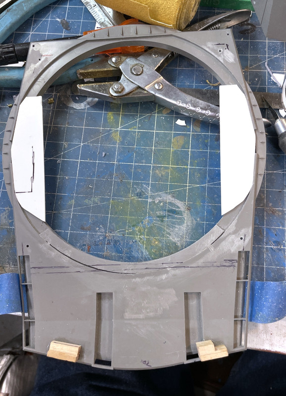
I did a test fit of the sight station to a) see if it aligned well with the flooring and b) if I could get the now-larger part into the model with the turret closed up. I could, just barely. This pic was taken before the floor was installed.
The last two parts to draw were the interior portion of the two turret periscopes and the vent structure. The exterior periscope portion is a Takom kit part. This interior part will have to be glued on the clear acrylic roof part that I haven’t cut yet. I found some good photos of it so the model is reasonably accurate.
The last part I’m going to print was the vent units that are prominent in the side passage. There are other ventilation structures in the turret, but I’m not modeling them. I’m also…at this moment… not planning on modeling the circuit boxes and wiring that’s on the back turret wall. I may change my mind again.
Here’s what the FINAL PRINT looks like on the slicer. As I’ve noted many times, resin printers don’t care how much stuff is on the plate. It doesn’t affect print time one jot unless what you add is taller. Height determines number of layers which in turn determines print time. FDM printers DO care about number of objects since they’re created one string at a time. So I really loaded up this run with all the punch list items. This includes the acess ladders from the rear gun compartment to the pan deck. This is used by primer man to get down to his duty station. I’ve added some separate floor hatchs which I will place in strategic locations. It has the missing air bottle from the first level projectile flat, the periscopes and finally those vents.
I started the restoration of the projectile deck. I filled the small damages and restored the opening for one of the access hatches. I have to rebuild the lower wall under one of the scuttle openings. I’m cutting some shaped styrene sheet to back up that large space and will then either use epoxy with micro-ballons for filler or more Bondic. Bondic on UV resin is marvelous since it’s the same material and binds and blends flawlessly. I’m going to have to use thing sheet since I don’t want to elevate the Ofc’s Booth massive print’s install height.

So dear readers, we’ll be enterning a new phase… constuction. The printing was a massive undertaking. I have almost 1,000 files in the turret sub-directory, split between drawings, screen prints and imported reference material.
I’ll be posting later today with today’s output. Stay tuned.
5 Likes
Maholo Brah ! Enjoy Maui - be sure to surf Thousand Peaks for me .
At 77 and having never surfed before in my life … although I can play terrific surf music on my Fender Strat… I won’t be surfing anywhere, but we will eat a ton of great food.
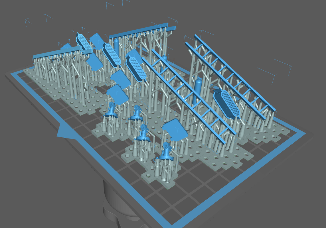
I got a really nice rendition of the air bottle sets that line the outer ring on the powder flat. I made four complete sets that will be in the foreground. Those that will be obscured by the rest of the turret will be left out. I based this drawing off of the pictures I took on that deck during the tour. I was happy that the piping survived the cleanup.
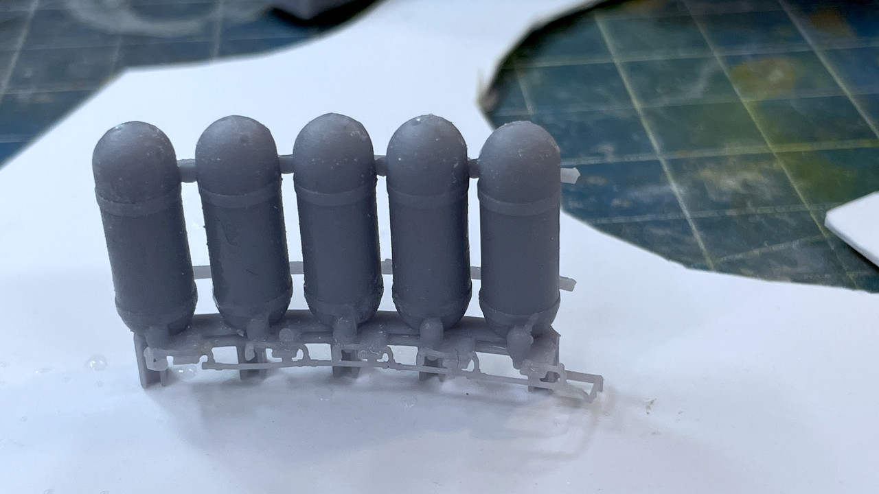
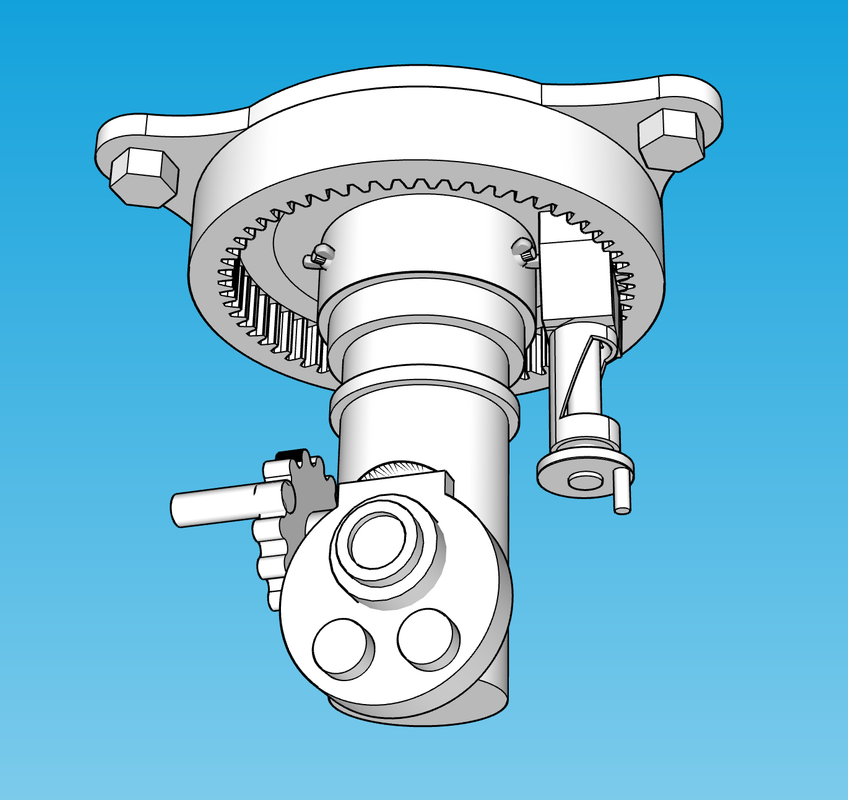
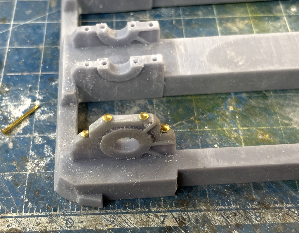
I also finished up the fitting of the traverse B-end. I had originally printed all of this machinery as part of the pan deck, but the results were sub-par and didn’t meet my standards. By separating them into separate prints including making the pinions movable, produced a much better job overall.
And I made one of the stupidest mistakes I ever made. I was all excited about getting that “last print” done. I emptied the machine of the previous parts using the very convenient Wham-Bam spring steel build plate. You pop it off the magnetic holder, bend it as for as it will go and the parts pop off of it. I give it a quick cleaning of IPA and then put it back on the magnetic sub-plate and you’re back in business in less than five minutes and you don’t have the slop of removing the entire plate assembly.
I started the printer and the job would take an hour and fifty seven minutes. I had a lot of other stuff to do and the printer was humming away. When it was done I looked at the job and my heart sank. The job was 80% off the build plate, just hanging there. Most of the parts didn’t even start to form. What did was almost unrecognizable. The it hit me…
I left the spring plate on the table behind me after cleaning it. I was attempting… unsucessfully… to print on a 3M rubberized magnetic surface, which, the last time I looked, was not compatible with printing anything. I removed the whole build plate assembly, cleaned it all off and restored the magnetic surface to what it should look like, and then put the spring plate back on. I had to empty the vat and pop off all the malformed pieces of semi-hardened resin that were stuck to it. The nice thing about the FEP2 film that Elegoo is marketing is its ablilty to recover after screwups like this. Stuck material just pops off leaving no damage. You don’t even have to clean the film, just wipe the slop off the sides, but it back on the machine and refill. I reran the job and it’s now finished.
The parts printed perfectly, and I’ll show them tomorrow. Meanwhile, I realized that I have just one more job to produce; the channel for the shell hoists that goes from the electric deck to under the cradle in the gun compartments. They’re already drawn. I just have to scale them and ready them for printing. Tomorrow!
4 Likes
Looking pretty good. I see you use Chitubox too. How’s it acting for you? For me, it won’t let me manually place any supports. It acts as though the part isn’t there in the first place so I can only use automatically placed supports.
I really love your work. It is amazing. Makes nostalgic of when I reported aboard the U. S. S. New Jersey BB-62, April 29, 1989. My first ship. And the awe and pride I felt walking down Pier 6 Long Beach Naval Station. Such great memories…
I hope it is not too late to point this out, unless you took some artistic licensing or have not added them yet, but it seems to me there should be an almost blank bulkhead running fore and aft separating each of the 16inch guns. But no matter what Sir you have done an amazing job and have every right to be proud of your project.
Phil
GMG1(SW) retired.
Oh… they’re on deck to be made. They’re not printed; they’re out of clear acrylic for the ones in the foreground and styrene sheet stock for the ones in the back. I’m hoping to cut the acrylic on the public laser cutter at UofL’s First Build Makery since it will do a better job. Those bulkheads go all the way to the bottom of the pan deck to separate the gun pits all the way down. It’s why you knew Under Siege’s guns were fake… they were in an open room.
I had to account for those bulkheads throughout the design to give them space next to the gun girders. When I first did it I had a rabbet groove in the girder for the walls for the sheets to sit in, but didn’t have them going straight through. On my 2nd revision I widened the girder spacing to accommodate them.
ChiTuBox Pro’s pretty good. It gives a ton of control. I don’t know why you’re having the trouble. Are you setting yup the STL converter so it’s creating the file in millimeters? You have to do that or it won’t recognize them.
Also try downloading Lychee. It’s a French product that has a free and paid version that looks pretty good.
The “Final Print” completed nicely. The quotes denote that it was not quite the final-final print. I realized this morning that I neglected to print the projectile trunks. These were already drawn so all I had to do was scale, export as STLs and slice. They finished tonight and are being cleaned in the ultrasonic. In that print also was a reprint of the missing air bottles on one of the projectile flats. For some reason, I got the scale wrong. That’s now fixed. I also lost one of the gun trunnion caps. I have to have 6 or them and only found five. They’re printing as I write this. The beauty of having this tool and the drawing skills is if a part is missing or broken, you just make another. I don’t erase any of the drawing files. Today, I did organize about 1,000 files into sub-directories in preparation to archive them at some point.
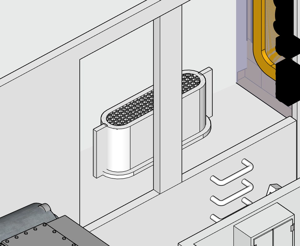
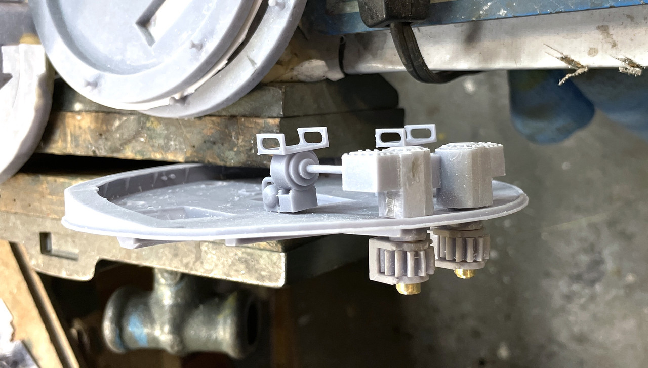
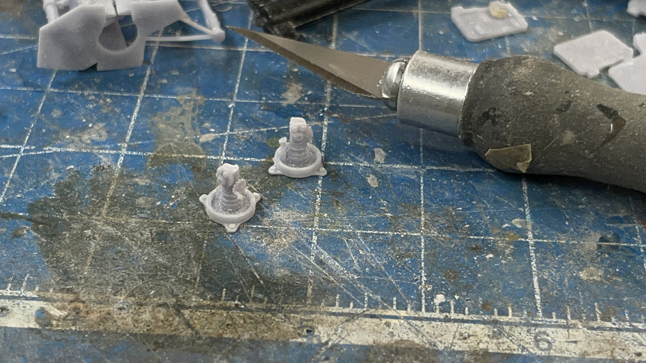
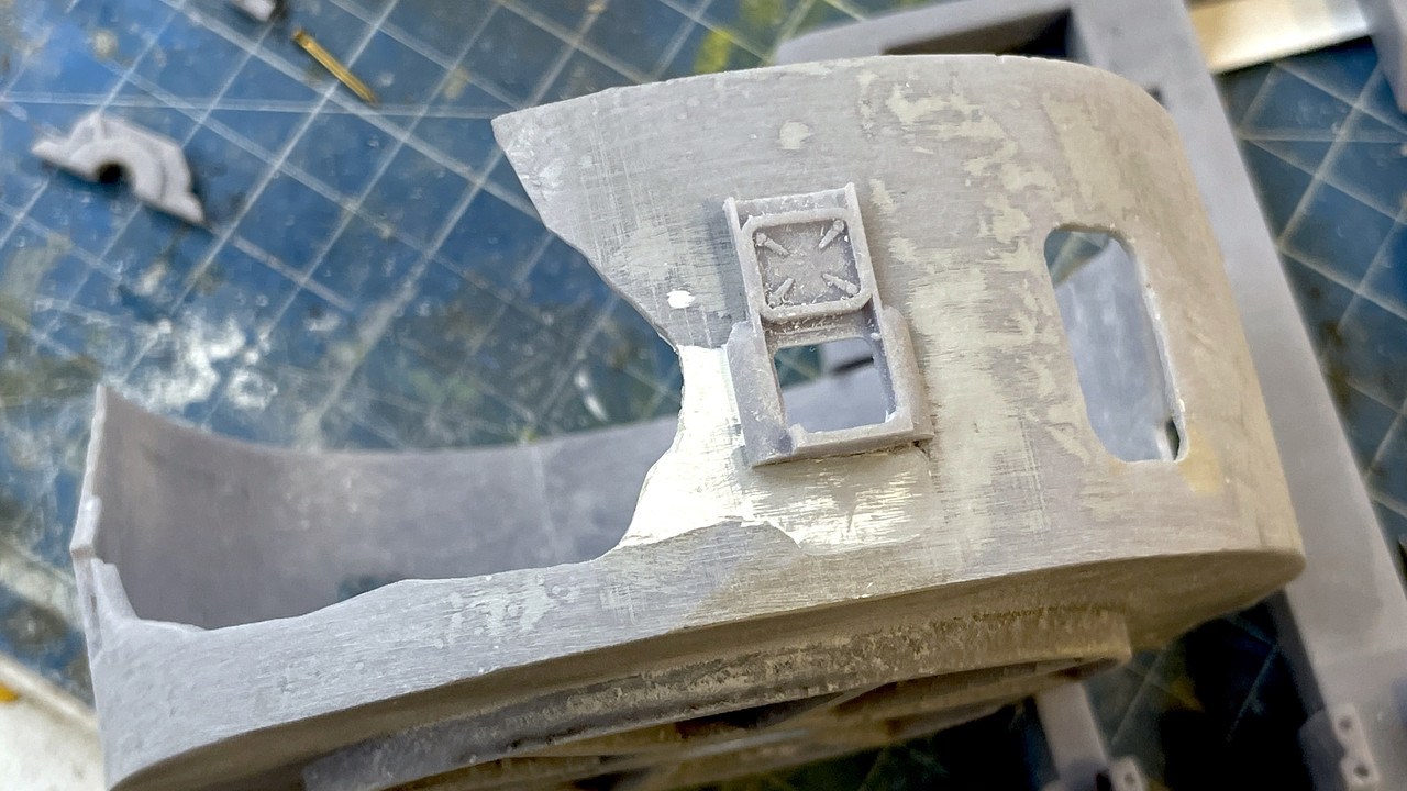
Here’s a perfect example of what a 4k monnchromatic LCD screen can do resolution-wise. I found a nice grating that I inserted into the drawing of the ventilator units that are in the side passges. I didn’t know if these small features would resolve. They did! So who needs PE? It still amazes me that this technology works and is available for a few hundred bucks. Just four years ago, it was $3k and higher… much higher. The monstrous Xacto blade shows the scale. I will fill the spaces with flat black and then dry brush the grills and they will look spectacular.
Another example is the tiny interior perscope units. There is actually a gear rack in the circumference of the mounting ring. You can just make it out. Again, the Xacto shows scale.
While the projectile trunks were printing, I arrayed all the parts save those few missing pieces to show the whole deal. It kinda blows my mind. Each one represents a drawing that had to be made and scaled, sliced and then printed. The number of parts is probably 50% more than you see from the extras and rejects. I have a pile sitting on the side of my work bench and a lot went into the trash.
I haven’t counted them. It’s well over 100. And not a single part number or instruction as to where to put them. It’s all in my head. Thank goodness at 77, the head is still sort of working. There are a few duplicates floating around in this pile, but not many.
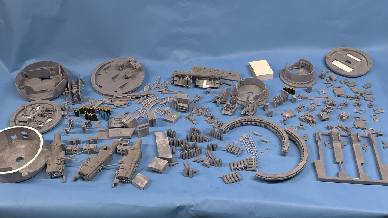
What is not shown in the above are the sheet stock parts including all the gun compartment partitions, the outer shells, the pan deck walls, and the non-rotating platforms of the two projectile flats and powder flat.
The rest of today’s session was spent restoring the powder flat. For the massive missing area, I made a styrene backing
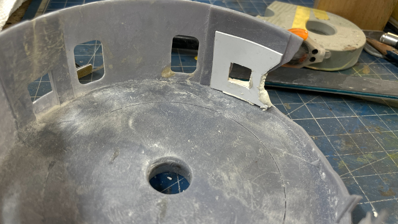
and then appliled Milliput epoxy putty to create the missing wall.
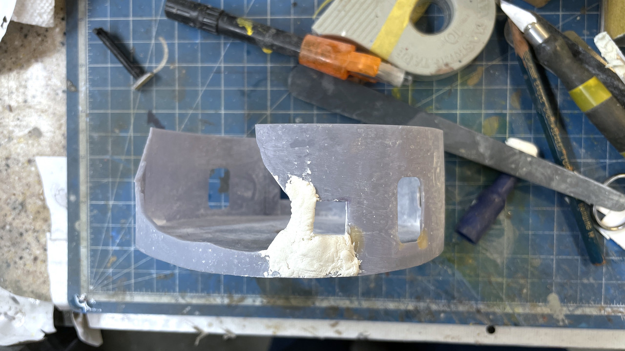
It will be fully cured tomorrow and I will sand it to the proper contour. I also filled the discontinuity that ran down the side in another area. In this case I used Bondic in four applications hardening each layer with the UV pen. When painted it will be invisible.
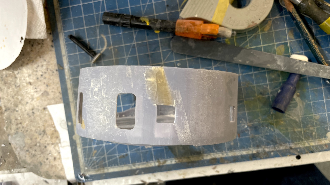
Lastly, I applied some Tamiya filler to the few depressions in the Powder Flat decking. It took a ton of elbow grease to level all that overgrowth out of the part, but it all went away. I went around and fine tuned all the square openings to fit the exterior portions of the powder scuttles so they all fit nicely. Tomorrow I’ll finish this part and get working on finishing up the electric deck adding some missing partitions.

Hard to believe that the above looked like this. If I had any chance of re-printing and having more success I would have done that. But it used a ton of expensice resin, and I have the skills and materials to restore it, so I chose that route. I’m not disappointed.
Works continues apace.
4 Likes
Now the printing is really done (I think or until I break something and have to remake it.). There is one more small detail in the ofc’s booth that I may add. It’s small handwheel and linkage that opens and closes the armored shutter that closes off the long-base rangefinder’s outer door. It’s really tiny and may or may not be noticeable. I also still want to see if I can make a reasonable rubber rangefinder bloomer. For that, I’m going to form the diaphrams shape out of Sculpey and then apply layers of black, liquid electrical tape to create a real rubber bloomer. It will be an experiment.
The repairs to the powder flat are complete and did the job. I can now continue with the painting and installation of the scuttles (front and back), quench tanks, and the lower leverls of the powder trunks. I’m going to paint all these pieces BEFORE attaching them whenever possible. The surface doesn’t look smooth, but it is.
I also printed the projectile trunks that run from the electric deck through the pan deck and terminating at the base of the cradles in the gun department. I chose to hollow these parts using this feature in the slicer which reduces resin use. You also put holes into the part at the top and bottom so the non-cured resin inside can be flushed out. The software created holes okay in one end, but I could seem to get them in the other end and chose to drill a vent hole after printing. The drilling went okay until it broke through into the hollow space and caught the drill momentarily. This shock broke out chunks in the two trunks with the curves. I glued them back on, filled any remaining spots with Bondic, finish sanded them and they’re like new.
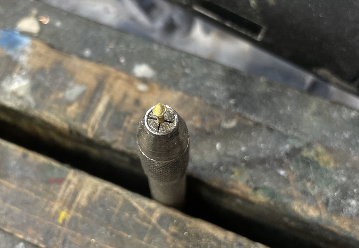
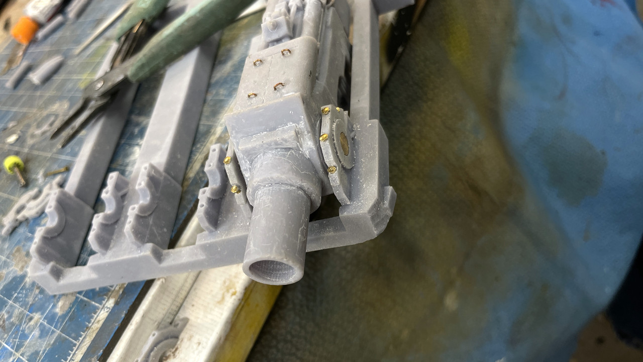
With ALL the parts printed I actually got started building something. I started fitting the trunnion caps onto their bases now that I have a full set (they were printed last night too). My caps are not prototypical. The actual caps would have been too insubstantial to build in this scale with resin. They just close off the very top of the bore. I chose to make a full cap which would work in this scale. To fake the bolts (aslo different than the real one) I’m filing the tops of some brass brads to form a hex head. I had to open the holes in all the parts to a #55 drill to match the brads’ diameter. To file the hex I’m holding the brad in a pin vise which in turn is held in my bench vise.
Here’s what it looks like assembled. This part will be somewhat hidden under the remaing turret roof.
And here’s the left gun in place with the first two trunnions. Nothing here is glued. Lots of painting has to take place first.
While I was fussing with the gun I had to be very, very careful I didn’t damage this…
The elevating scews ARE permenantly attached and I don’t want to break them. Thank goodness for my resin blend that does have a lot of resilience and bends a lot before breaking. Without this blend, I would have broken that lead screw today, I’m sure.
Everyone have a nice weekend. It sure feels weird not having to draw or print anything like I’ve been doing since January.
5 Likes
Absolutely amazing work!