Just did a binge catch up with other threads along with this one. Some great updates and recoveries from dodgy printing. So much detail and it’s so good to see it all here as I can imagine a lot will be sadly hidden away nearer completion… Great work and engineering ![]()
Thanks guys! Yes, a lot will be hidden, but I’m going to try and show some stratgic areas that will keep people interested. The LED lighting will certainly help. I’m going to substitute 5/8" PVC pipe for the copper tubing for the central column. This will facilitate drilling holes for wiring, gluing the decks in place, and drilling and gluing the ladder rungs that go from powder flat to electric deck.
1 Like
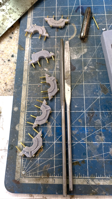
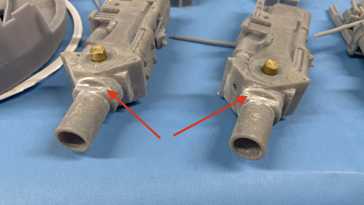
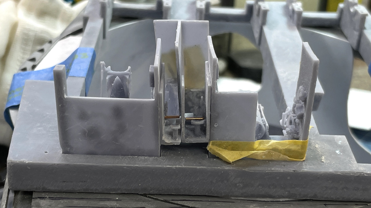
I finished up making the faux bearing bolts and then line bored the trunnion bearings with a 1/4" reamer. There was some slight misalignment with the trunnion lower and upper portions. Don’t know why… possibly some slight deviation in the scaling factor. No problem. The guns aren’t moving anyway.
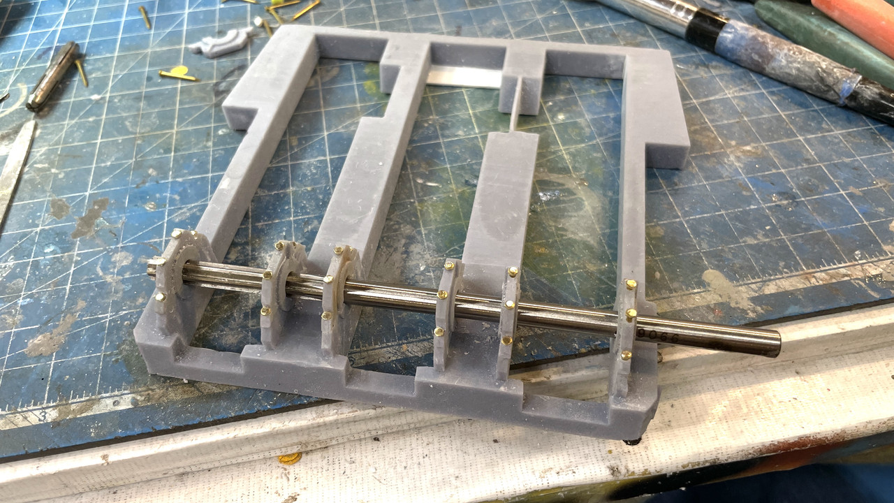
I found some slight variations in how each cap ended up so I marked them so they’ll go back in the same place. I then CA’d the “bolts” in place and will simply drop them down and glue them AFTER the guns are installed. That’s a ways down the line. I will put them in place for gun girder painting (but not glue them).
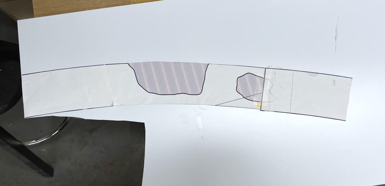
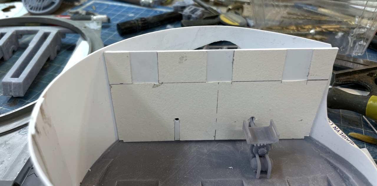
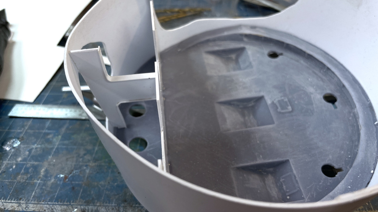
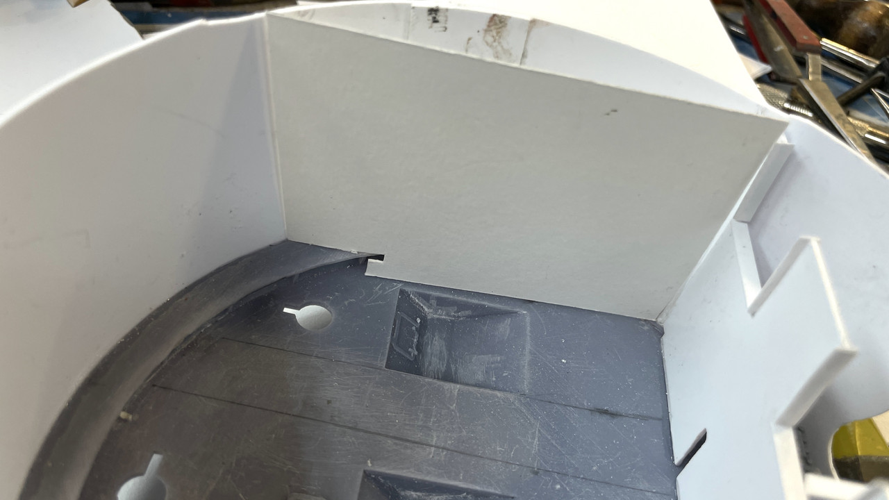
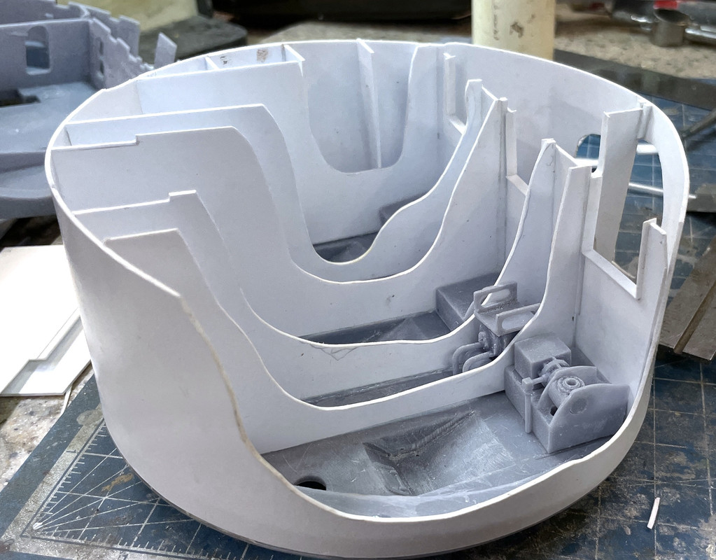
Then I got down to some serious work and it was a joy. I needed to build the complete pan deck because I needed it at full height to fit certain items. These items are the powder trunks and that have to pass from the pan deck base to the top of the gun house minus the thickness of the planned acrylic roof. This required creating and attaching the conical wall. I had created its pattern in SketchUp and test wrapped the paper around the rim on the pan deck base. I adjusted the diameter to get the best fit.
I then applied a light coating of MicroMark Pressure Sensitive Adhesive (PSA) around the pattern perimeter and stuck it to a sheet of 0.040" styrene. I aligned one straight edge with the styrene edge and used a steel straight edge to scribe the other end so they would butt up decently. I then hand cut the perimeter with a #11 blade, going it over about 4 times and then snapping off the part. Notice that the cutaway areas are already noted on the plan and I cut them out with the same method BEFORE forming the cone.
I made a splice plate out of the same material and clamped it with two hemostats and test fit the plastic part on the pan deck base. I was rewarded with a PERFECT fit. That’s when the joy began. Of all the work on this project, making these cylinders and conical shapes AND getting them to fit was one of the most anxiety producing aspects for me. I have a friend from a model railroading forum, Al Graziano, who produces refinery and chemical engineering models as a business and builds cylindrical shapes all the time out of styrene. He’s a master! I am not.
Here’s the forming of the cone with the forceps holding it in place. The splice plate doesn’t go all the way to the bottom since it has to clear the fatter section of the pan deck base.

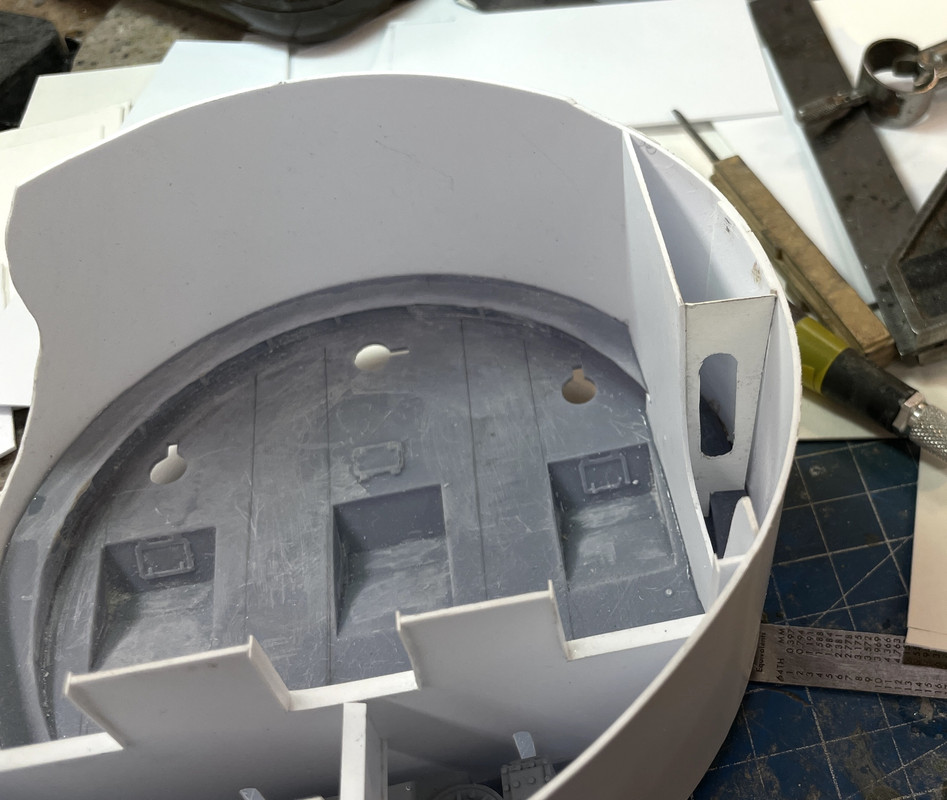
The moment of truth was when I was able to install the cone on the base. I engineered a little ledge to catch the cone and it worked as planned. The part fit like a glove. There were some irregularities in the bottom and top edges (they were cut by hand), so after the glue set (helped along with a little CA) I trued it up on my flat surface sanding rig (a piece of sand paper glued to a granite surface plate. The mini-C-Lamp is there to compress the center of the joint which needed a little more glue to fully seal.
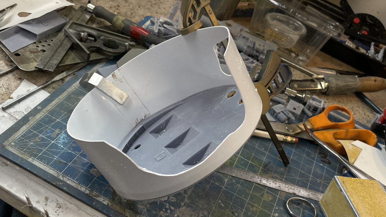
The PSA left some residue in spots around the part which I removed with a rag and some Goo Gone. I sprayed the inside of the joint with accelerator and then went around with thin CA for the first application. Since the wall is actually a shallow cone, it did not fully snug up against the upper edge of the thick part of the base. I filled this opening with some medium CA. I then went around the outside of the joint with med CA and accelerator to further seal that edge. Finally I filled any remaining imperfections with Bondic.
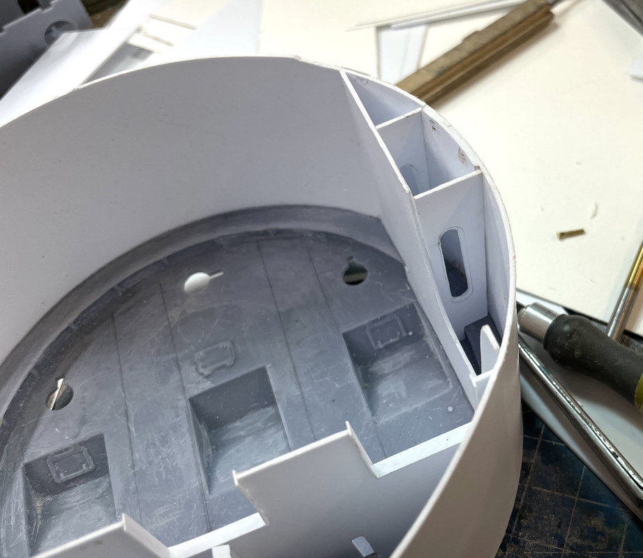
The next “Moment of Truth” was how the now-assembled pan deck interfaced with the Takom turret house bottom. Again I was rewarded when the cone slipped perfectly inside the large raised kit rim. With that, I could move on to the next task; fitting the upper portions of the powder trunk. I am not ready to glue these two major components together yet. Painting must come first.
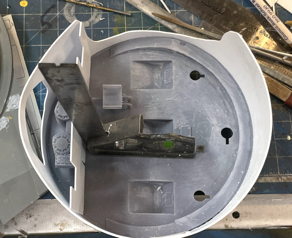
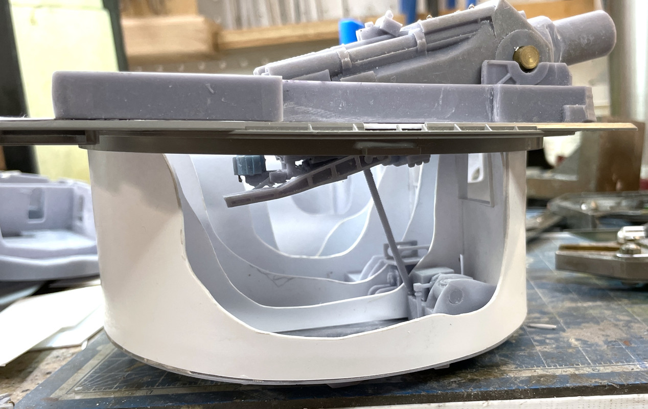
The trunks appeared short to me… a lot short. When drawing them, I never was sure just where they were supposed to end up, and they ended up about 6 scale feet short.
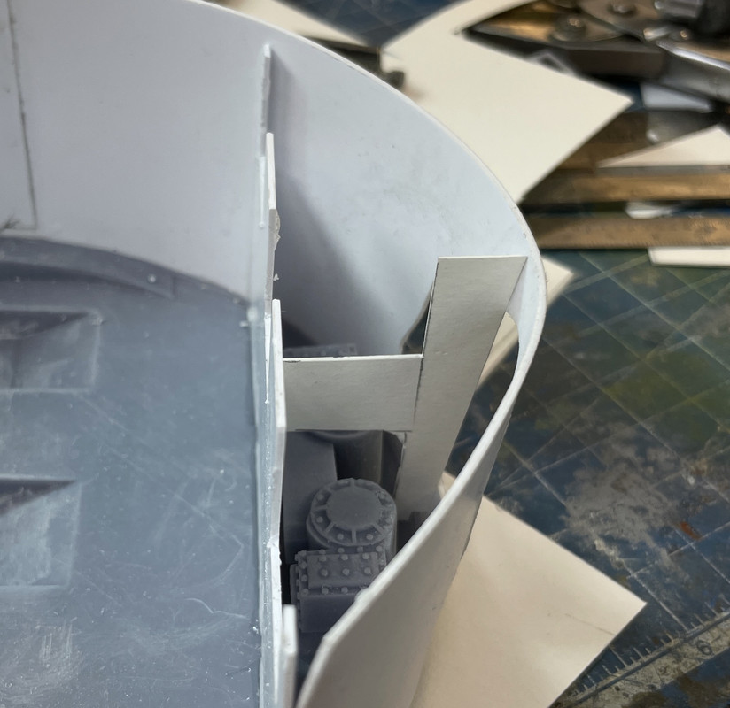
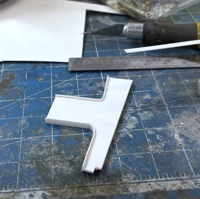
Before I could place the trunks I had to final fit them to the slots in the gun girders. The single trunk pretty much dropped in. The double trunk slot needed some surgery to get it right. I had to remove the center bar between the slots. I knew this had to go during design, but left it in for printing to give more stability to the part during formation. I also had to reshape the angle on the rear wall of the slot and removed some material. Once fitted, I taped the double trunk into the desired position (about an 1/8" before the uppper gun house edge). I then measured how far it was floating above the pan deck base with a dividers, transfer this dimension to some styrene and cut out the parts to make a parallelogram box. I traced the trunk itself to establish the angles. I’m pretty good at extending things that are too short. It’s an essential scratch build skill.
I needed to add and subtract some material in various spots to match the actual contours of the double trunk since the two sides are not symetrical. I then finished sanded and filled any spots and this one was ready to install. i then got to work on the single trunk. it too needed an extender, but it was slightly shorter that the double.
Here’s a shot of both trunks test fit with their finished extensions.
Here’s how the height works out.
Here’s a finished trunk. You can’t really make out how nicely I was able to blend the new to the old. The extension is being held with Gel CA and then some thin. (plus accelerator).
With the two trunks ready to go, I had to do the final fitting of the powder cart operator’s booth. With these parts too I was unsure of how they would fit when I had actual parts. I was expecting to do some surgery.
I put all the parts in place for the right side gun back area, aligned the booth to the trunk, scribed the overlap, and then cut the trunk to mate with the booth.
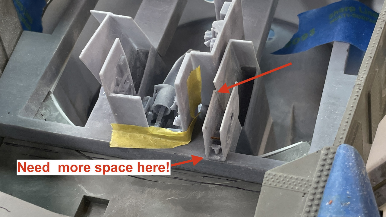
The upper arrow shows the interface. The lower arrow shows I still need to move it forward needing about an 1/8" ledge to mount the rear bulkhead. I will remove more material from the trunk wall to get this extra space. The trunk and the alcove panel next to it will be glued together in the final assembly.
It was a nice long work session and in summary a very eventful and successful one!
5 Likes
Loving your work. You seem to have a fairly solid working knowledge of sketchup, of which I’m a huge fan. I’d love to see some of this with some primer on.
I have similar dreams of doing B turret from HMS Dreadnought, along with sections of the hull and possibly bridge. But I need to finish my Hunley first.
Good luck on the Dreadnought project. You’ll need a ton of reference drawings. Turrets don’t have a lot of square corners so getting the geometry right is a significant challenge for me. That’s why the Takom shell was so instrumental is getting the project off the ground. I never had a decent drawing of the turret exterior showing all the angles. Everything slopes! The 5" turrets had sloped roof and front face, but the side and back walls were vertical. Not so with the Iowas. Only the back wall was vertical, but curved laterally. The roof was flat, but all the rest sloped in both planes. Maybe Takom will come up with a Dreadnought turret?
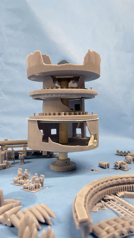
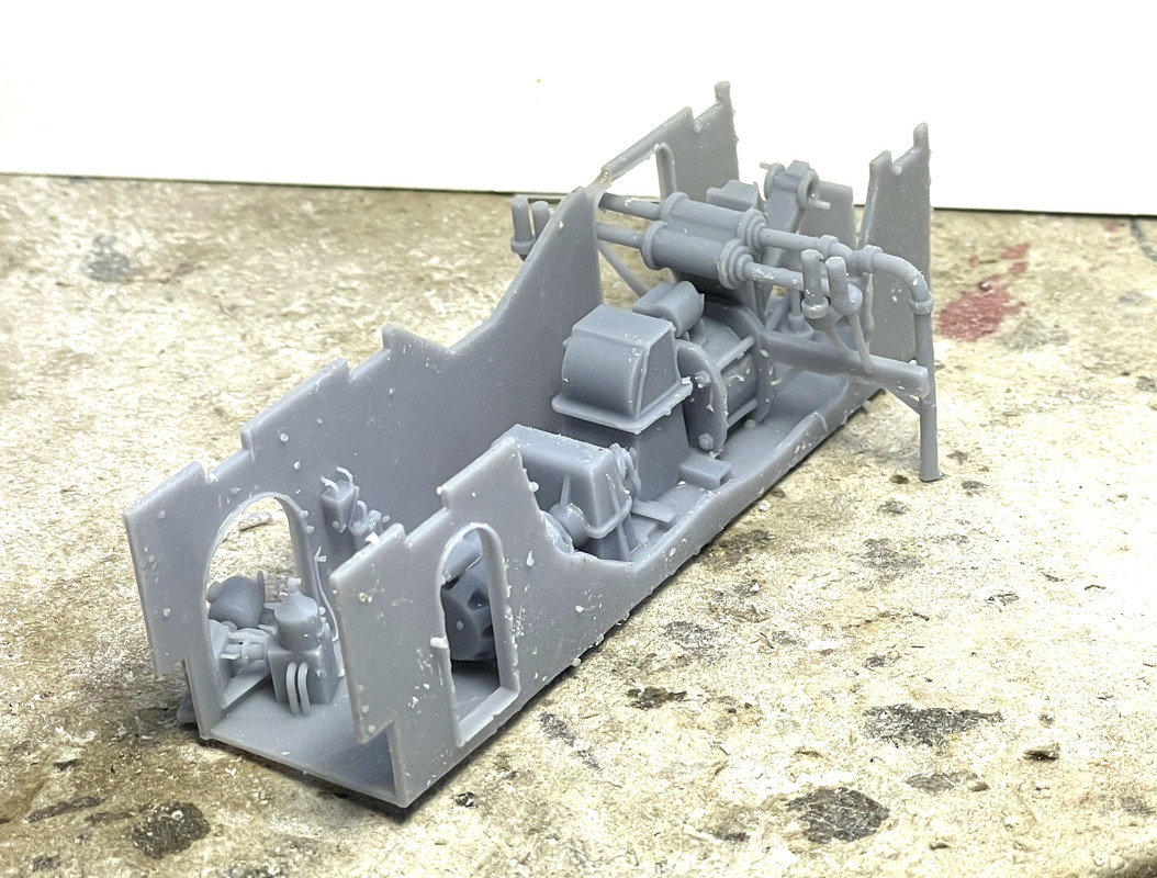
All right sports fans, get ready for a big photo dump (22). Unlike the 3D printing phase, the construction phase produces a lot of WIP photography with lots of various things going on. I was concentrating on finishing up the pan deck to get it ready for paint, and was still fussing with the gun girder. First let’s tackle that.
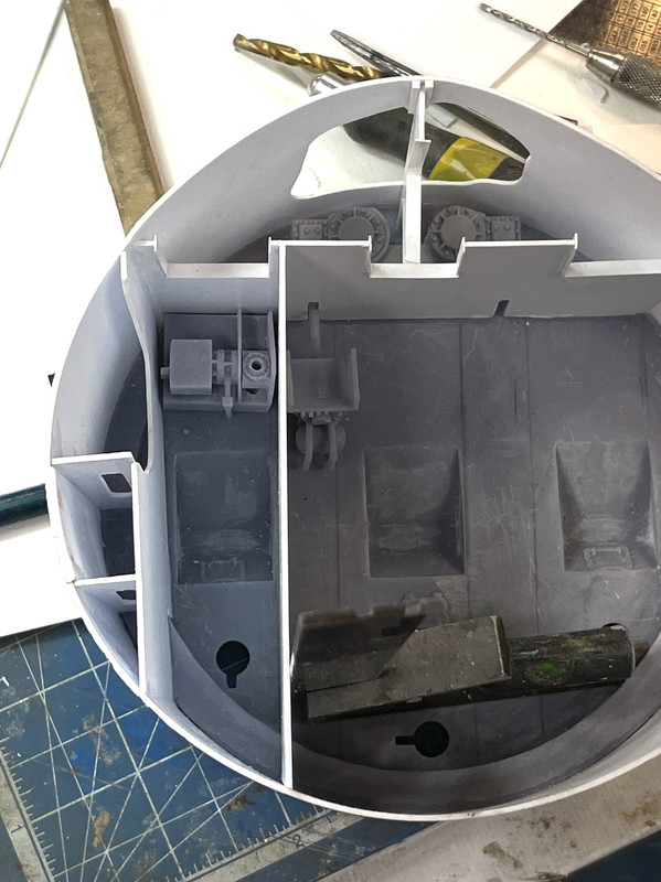
I found out why the trunnion caps weren’t aligning properly. After checking my master SketchUp drawing I found out that I had them on backwards. When I turned them around they fit fine. I also needed to check how the guns were fitting since the position of this girder on the kit base was further forward than the last girder I printed. Glad I checked. The new position was pushing the guns forward by about 1/8" and they were jamming in the kit opening. I didn’t want to move the girder back since everything else about the position was perfect including the ofc’s booth fit. To solve this problem I made some relief cuts in the gun manlet and the guns fit fine.
I then checked them with the kit’s plastic bloomers and everything still worked including how the metal barrels engaged with the gun slide. Whew! Dodged that bullet. All of this mayhem is completely invisible in the finished model.
I then spent a lot of time fitting the gun rear compartments and the powder hoist operator’s booths. The reason for all this fussing was the addition of the kit turret floor piece. I did not have that part as part of the design phase. It was just too hard for me to figure out what was what with it and I fully expected to do a lot of “field mods” to get it all to work. My expectations were correct.
The first problem was relieving the bottoms of the compartment prints so they would drop down and back to the correct final position. This was a trial and error affair. I did the cutting with the Dremel Flexishaft and a diamond coated cutting wheel. This job creates a huge amount of UV resin dust and I wore my dust mask so I wouldn’t kill myself.
I also kind of knew from the start that my design of the powder hoist operators booths was going to cause a problem since in the rear ship, they share a common wall in the double hoist area as the powder trunks do. I produced them with two side was each. This is what it looked like when those two walls were trying to occupy the same space. Physics won’t allow this.
I had to surgically remove on of the walls. I also had to do major surgery on the edges that mated with the powder trunks themselves. Again, I new as I was drawing all this that I had absolutely no idea just how all these pieces were going to interact until I had the physical parts. After removing the wall, they do work together better. I CA’s each respective hoist booth their gun compartments since the little observation window openings had to align for the booth to be at the proper height. I’m not worried about the open space beneath since the rear bulkhead butts up directly to these parts.
The other two guns powder carts will be down at the powder flat.
The right gun is going to have the powder door open with the cart in the upper position. It was especially trying to get the cart, the trunk and the rest of it to all work together. This is how it ended up. Again, the alcove part back wall with conceal that opening you see showing the cart’s flank.

The last gun girder task was putting the thin styrene veneer on the rear compartment to act as the turret base plate. I made a paper template and then transferred this to the 0.020" styrene using the same PSA technique I used before. I will be using this technique a few times before the job is done.
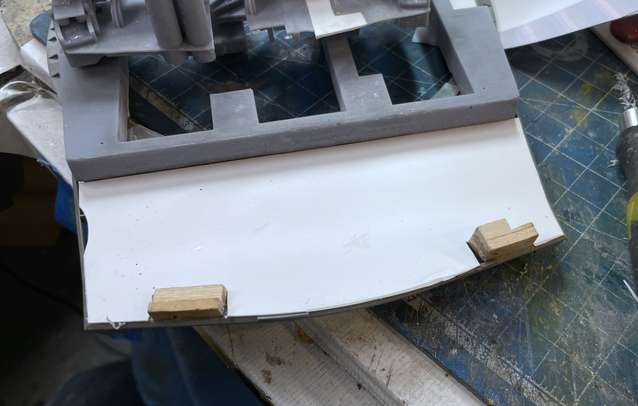
I test fit the rear compartment print to make sure that small lift the floor gave didn’t cause any problems. it did not. This floor will have the non-slip flooring in the walkway like the prototype does.
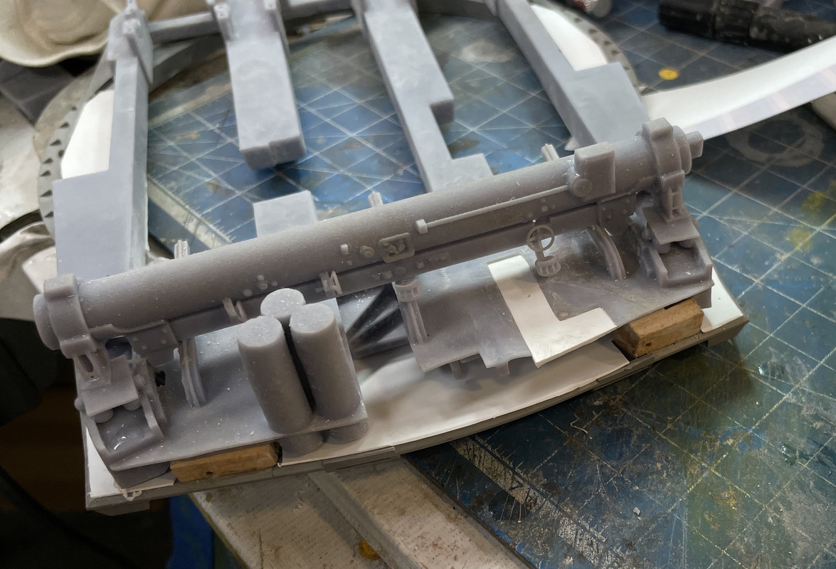
I believe I can paint the gun girders now.
I got bacl to work on the pan deck. I had made a paper template of the transverse bulkhead that runs athwartship just behing the training machinery. I pasted the paper template onto a heavier strathmore stock and started doing the final fitting. I don’t know why, but I found it necessary to make relief cuts in this bulkhead in SU. The guns were impacting it. I don’t know the actual dimension of this bulkhead in the real ship. Since so many of my measurements are estimates I could have some stacking errors that crept in with the guns themselves. Just because they look great doesn’t mean they’re exactly scaled.
I added some height to my original drawing so it matched the height of the pan deck’s walls. I then glued the strathmore template onto the 0.040" styrene.
I had to keep adjusting the width and positioning to get it just right. I went back and measured my full-size SU drawing to capture the distance from the front of the shell to the bulkhead and then divided by 72 to get the actual number. My positioning was very close.
Another critical dimension was the positioning of the slots that the B-end hydraulics drive shaft that must align to the holes in the gear heads. It took a bit of fiddling to get this one right.
I used a square to hold it in position while I started with solvent cement to tack it in place.
After the solvent cement set a bit, I went back and sealed all the edges with thick CA and accelerator. I will attach the B-ends AFTER all the pan deck is painted.
With the front bulkhead done, I crafted the center bulkhead that lies above and between the two gear heads. I had to notch this out just like the tranverse bulkhead to clear the gun, especially when they elevate and all the recoil mechanism on the bottom swings down. I’m only elevating the left gun, but the bulkheads have to look like the others could too.
This piece also stabilizes the flimsy area in front as a result of all the cutaway work. Again, started with Strathmore, then transferred to styrene when it was right. This shows the Strathmore.
When the fit was right, I made the real one. In this case, I radiused both cut outs. I then added some 0.020" X .125" styrene strip to act as the typical welded webbing on all the perforations in all the bulkheads throughout the entire ship. This was fun, good old, old school scratch-building.
I did a final test fit, and liked it.
Now I had a decision to make. I couldn’t glue this in if the training gear wasn’t installed since I couldn’t get the training gear in with this bulkhead in place. But I wanted the bulkheads to be all glued in before painting. I bit the bullet and prime painted the gear head, and installed it with thin CA. I then final glued the front bulkhead in place with solvent and CA as before. I then added some reinforcing blocks around that front butt joint. I didn’t want it breaking loose. These are behind the wall and won’t be visible through the cutaway. I’ll just have do some fancy brush painting to do the gear head.
I put the webbing on the center buikhead so I had to put it on the transverse one. Finicky, but fun.
With everything glued in place, it’s now ready for paint.
Here’s the view through the cutaway.
I did one more print job.
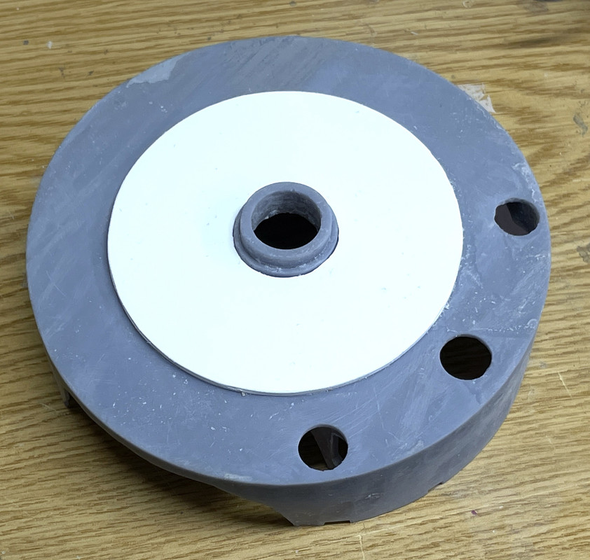
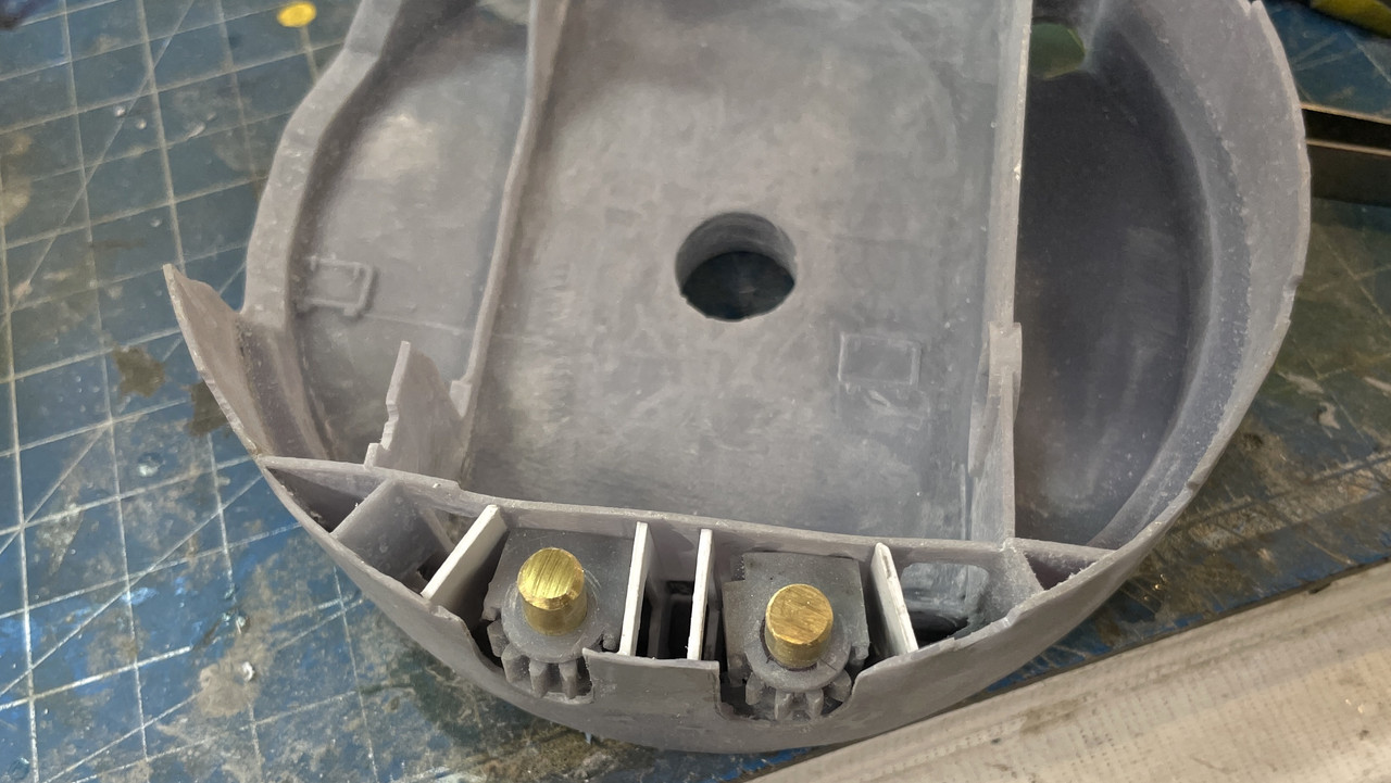
I was trying to figure out how to support the model on the display base. I was going to machine a part out of brass, but then said… “Draw it and print it”. It’s going to be below the base underneath in the circuitry box. The leads for the LEDs will come out of the hollow CPVC tube below the base. The screw holes are just place holders since I don’t know what hardware I’ll be actually using.
The printed through hole is a couple of thousandths under 5/8" so the copper tube wouldn’t get all the way through. i turned it into a ream by grinding a slice in the tube’s edge and a cutting lip and by twisting it, let it open the hole up enough to pass it. It worked. And the plastic tube is a nice tight slip fit. This is the bottom that will be in the box.
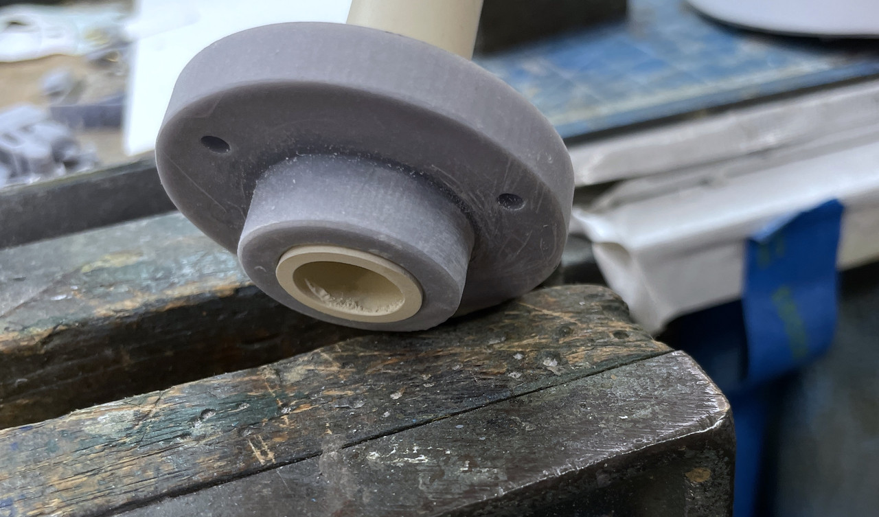
And this is the mounting surface that will go up against the base box surface. I notice a discontinuity on the one of the screw bosses. The radius didn’t form a solid around that one. I hope it will work as it is.
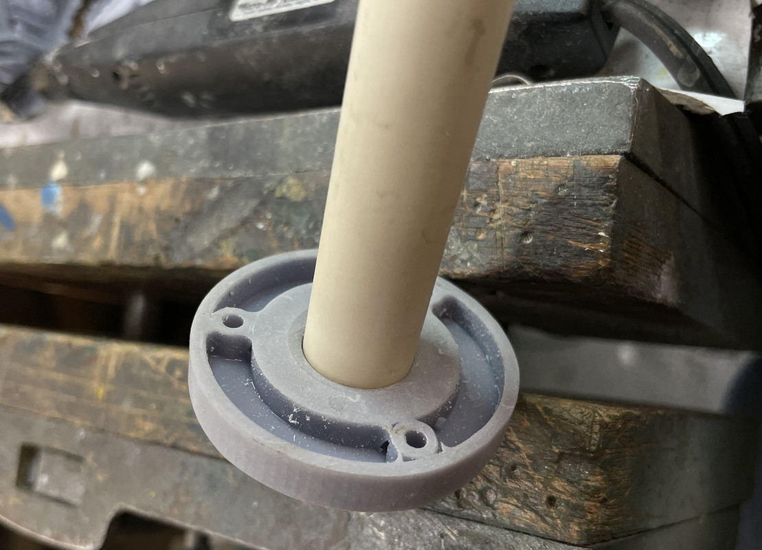
I did a quick estimate of the center column height and cut it off with my big chop saw. I put the stack together just for fun. It does not penetrate the electric deck. It sits in a socket, but as I’m writing this I realize that I will need to find a way to get all the wiring from the this deck, the pan deck and the gun house through that tube and down to the base. There’s a lot of bulkheads that aren’t going to have cutaways or be transparent so it shouldn’t be a problem. Just have to keep it in mind. It’s why doing all this journaling actually helps me produce a better model.
I don’t actually know the wood thickness that my friend is going to use so the spacing below the powder flat is just an estimate. The actual boss diameter is .79" which is bigger than 3/4" and I don’t know of a drill that size. I needed to give the walls some meat to support the tubing and the tube is 5/8". The boss is supporting the tube, not the base so the hole can be any size bigger that the boss.
Tomorrow I will tackle the electric deck. It too is going to have some scratch-built add-on small bulkheads.
5 Likes
Wow, if the Navy ever needs someone to design a new big-gun turret you are perfect for the job.
It sure feels like I’m doing naval architecture.
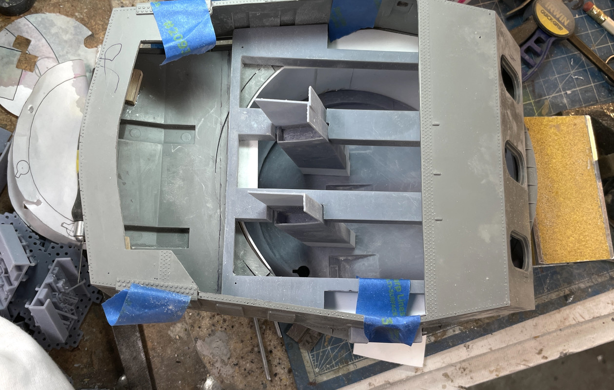
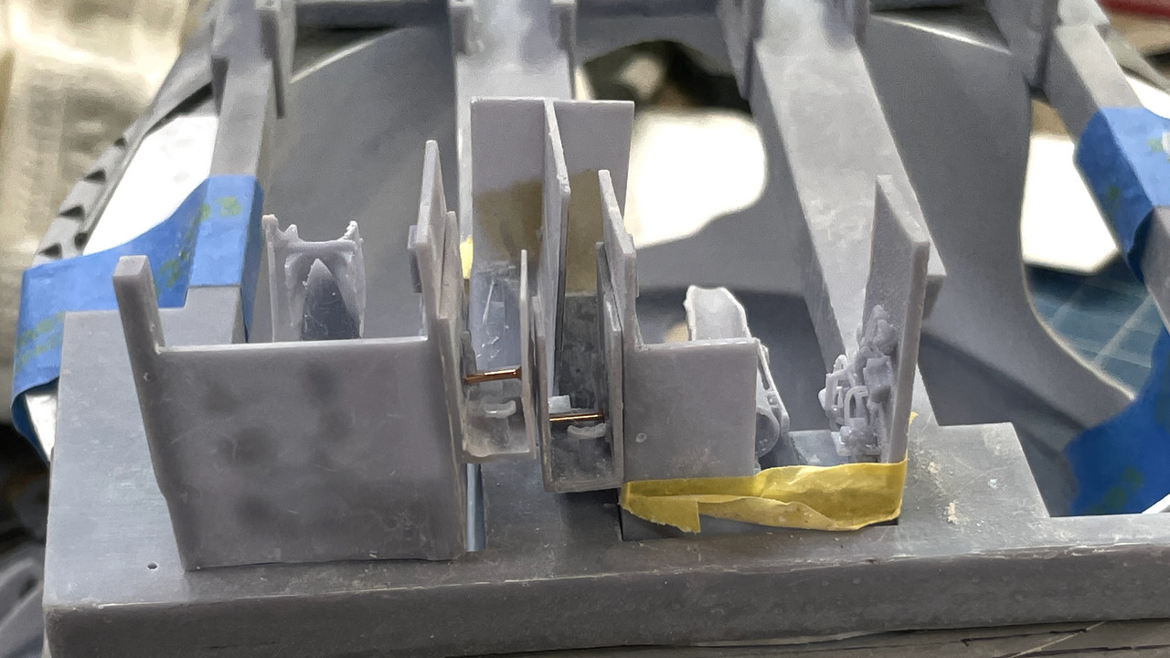
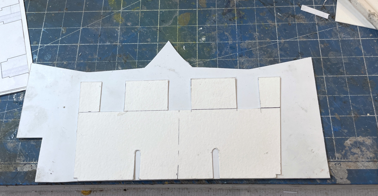
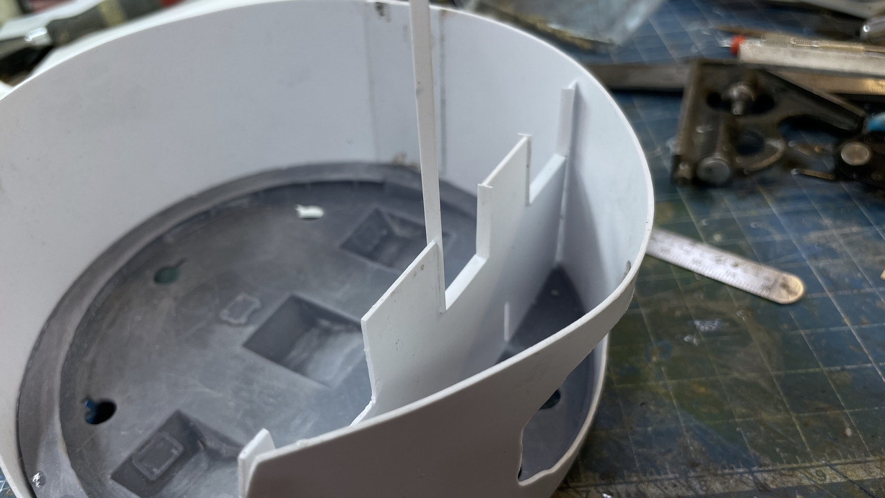
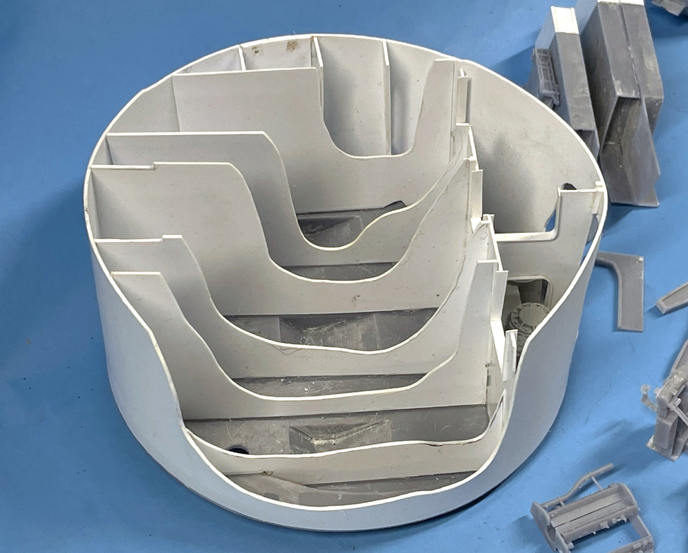
More work proceeds on the pan deck. Again using Strathmore art paper, I made three templates for the fore and aft partitiions. I then transferred to styrene, final shaped them and started to install. I’m not going to use transparent styrene. I have to use Med/thick CA to glue the styrene to the base UV resin and solvent cements have no effect on the UV resin. That means CA and it can cloud clear styrene. instead I’m just going to continue using the cutaways that were started with the outer shell.
I made another critical decision: I was originally going to apply the prototype’s method of having the partitions go straight down from the turret ceiling to the pan deck. This would have meant inserting the entire girder from the top and still be able to glue it in place at the bottom of the pan deck. That was bad enough, But the partitions sit ON TOP of the trunnion caps, meaning the guns would have to be installed first. The guns completely block access to the pan deck! This simply wouldn’t work.
Instead, I’m splitting the partitions with the lower pan-deck portion being measured and installed completely, then painted and have all the appratus installed. The gun house base structure gets painted, and all the apparatus installed. Then the guns go in with their trunnion caps and finally, the gun house partitions get glued to the flanks of the gun girders. I suspect that due to the spacing variations, the upper and lower pieces may not align perfectly, but they will be very hard to see and it’s the only way I can envision getting it together.
This shows the split template. These were originally a single sheet. Notice how the partition is cut to go on top of the trunnion.
I make the template larger than needed and then creep up to the correct fit. It is critical that the pan deck apparatus fits between these partitions. The elevating gear goes in the same space as the gun pit and the training B-end goes in the in-between spaces. My gun pit spacing and even the gun girders themselve ARE NOT as accurate as I would llke and the spacing has some variability in it. But the appratus has to fit so I’m using them as the final positioning guide.

I made all three templates first. Two of these, the middle ones, will be in pairs. The outer one is on the back wall, but not in front since it would block the cutaway.

The port side partition needed some more fiddling to have it clear the reinforcing girder that encircles half of the pan deck base. This too was cut out and shaped while still using Strathmore. Paper is much cheaper than scrapping badly cut styrene.
This piece was then transferred to styrene, solvent glued to the other styrene and bonded to the base using accelerator and medium CA. After installation I wanted to add these side bulkheads. There appears to be lightening/access ports in them which I cut, first in paper and then in styrene. While they would have had webbing, the radius is too tight and the styrene would split under action of the solvent cement. So I left it off here. These could have been 3D printed, but I had no idea of how big they would be until building it. This is the paper template.
Here it is with the styrene.
Here’s a view showing positioning of some of the apparatus with the next partition set in place. I haven’t cut the cutaway on this so nothing is glued here. On my original plans I had another tranverse builkhead going across the back, but after careful review of the plan I realize that this dotted line was something that was below the deck. I also am not sure if there’s a passage across the back from one pit to the other. I highly doubt it since this violates the whole philosophy of segregating anythng that could pass fire from one area to the other.
There would be one more side bulkhead spacer, in the fore part of that chamber, but it would be right in the cutaway. I may pit it in and cut it away too. That strange object that’s on the bottom of this image is my lovely Browne and Sharpe small combination square viewed end-on. I use it during the gluing to help keep things plumb.
7 Likes
Didn’t have much time in the shop… was buying stuff for the Hawaii trip. That said, did get some more stuff done.
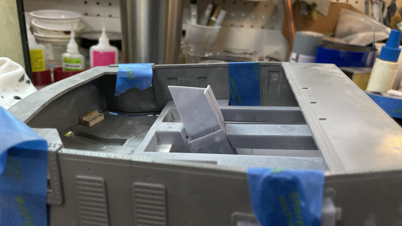
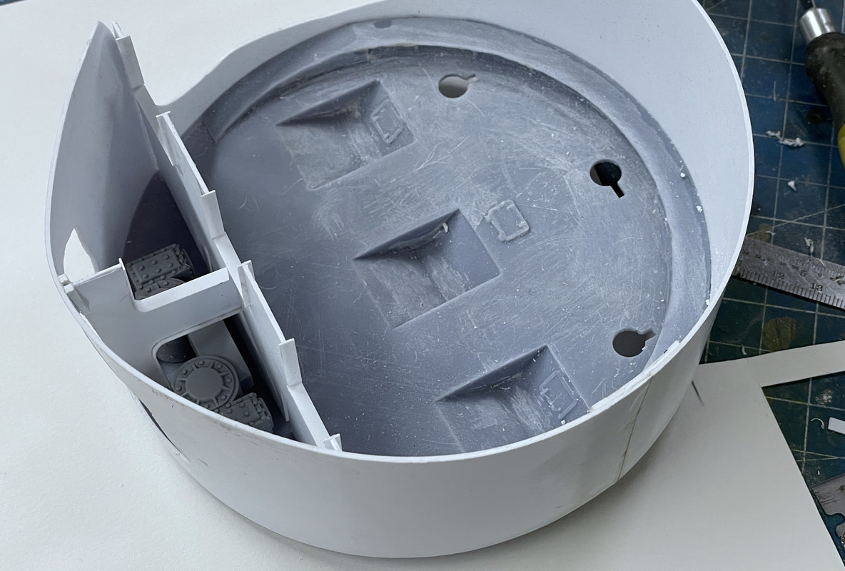
The pan deck partitioning is almost finished.
I was able to position all of them so the apparatus fit, but the variances I introduced in the gun girder land width definitely knocks the alignment off between the bottom and top partition halves. I was so concerned to get the gun spaces centered and correct width that I ignored the fact the the pieces in between the spaces were no longer equal. Forest and trees syndrome. Can’t do anything about it. That ship has left the dry dock. It will almost impossible to visualize these erros in the finished model since the guns and the aft gun compartment parts hide almost all the happenings in the pan deck below. That’s why the cutaway is so critical. Here’s what’s done so far. The apparatus is just there for spacing.
The relief cuts on the top of the middle two partitiions is for the piece of 0.040" styrene that I installed to give a positive stop to the middle gun compartment print. It protrudes into the pan deck space and the notches let the pan deck seat evenly all around.
I put on the gun house base and a gun to see what the view will be looking straight through. This is how viewers will see it. While it seems very light in there now… so why worry about LEDs, when all the stuff is on top it will get much darker and lighting will be necessary.
Painting all this will be fun…especially masking the walls so I can airbrush the deck surfaces. i thinking of outlining the cut edges of the cutaways with red or green to highlight them… thoughts?
The elevating box is the wrong hand for the right gun so the elevating screw is not engaged in it. Doesn’t matter. it was just to get an idea of view.
Have a great, happy and safe Labor Day weekend!
10 Likes
Wow, impressive!
I like the idea of highlighting the edges of the cutaways.
Red seems to prevail on real-world cutaways where the cuts are obvious, so it would seem the obvious for a model where the cuts are less so. However, I’m wondering if a simple “bright steel” colour would work as well without being so garish?
Regards,
M
1 Like
I’m posting this thread on four different forums (all differrent audiences and viewpoints), and the consensus seems to be heading red. I’ll see if there’s any more input and then finally decide. That’s the trouble with asking for opinions. You get them, and like belly buttons, everyone has one. Keep them coming.
1 Like
Do what YOU think best - I know the adage “ it takes a village to raise a child “ but in the end the parents should have the final say and there can be no doubt this is your baby !
Yes it is! But I still might go read.
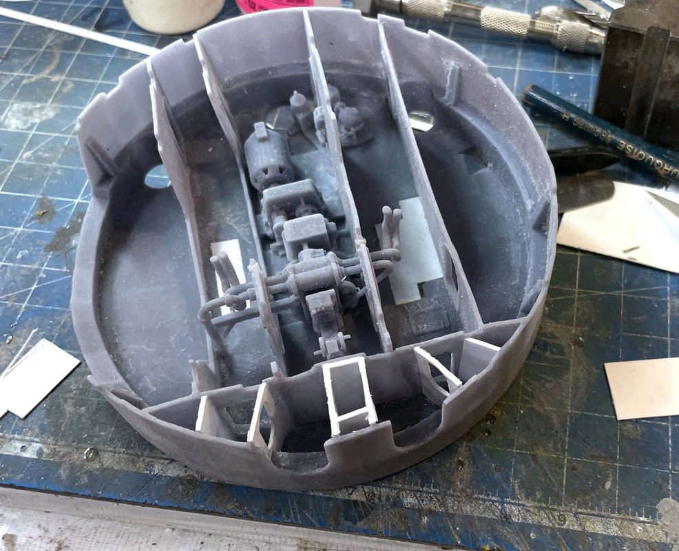
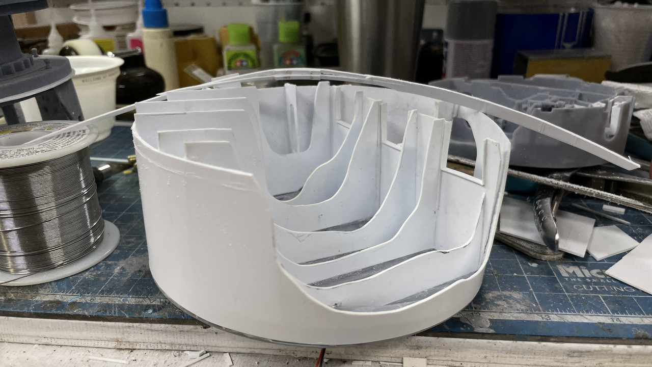
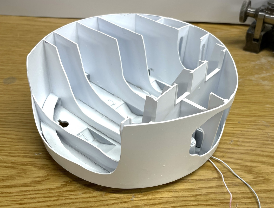
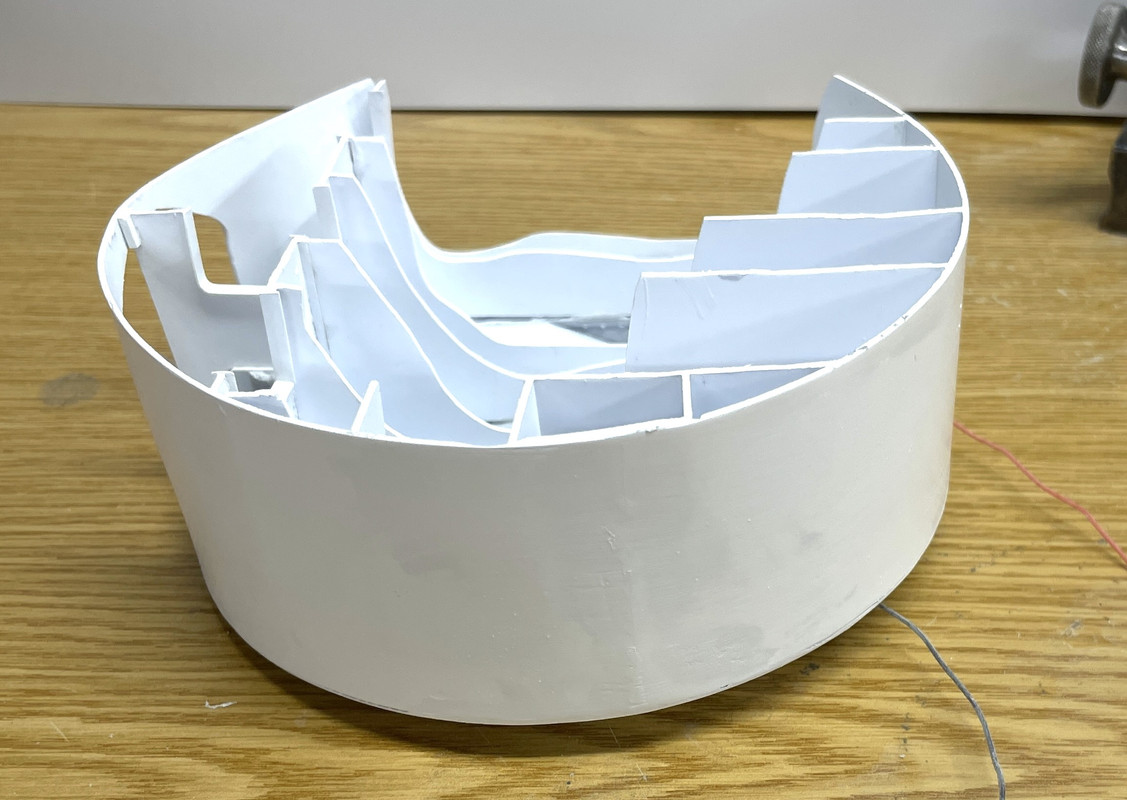
Even though it’s Labor Day I did get some shop time. Finished up the Pan Deck partitions with the small cut down one in front. I cleaned up the edges a bit more and it’s waiting for paint. LED wiring will come down behind one of the back bulkheads out of sight.
I started working on the electric deck and almost got it ready for paint too. I glued in that complex mid-section print with the training system and one of the projectile hoist power packs. I also had to do the cutaway on the this part’s port side wall so you can see into it. I used the Dremel with a carbide router to make the cuts. Resin doesn’t melt like styrene and works well with burrs and other high rpm cutters. Styrene melts so fast it just gums up the tools.
I did the fill-in bit like I did with the projectile flats to close the rectangular holes for the old design powder trunks.
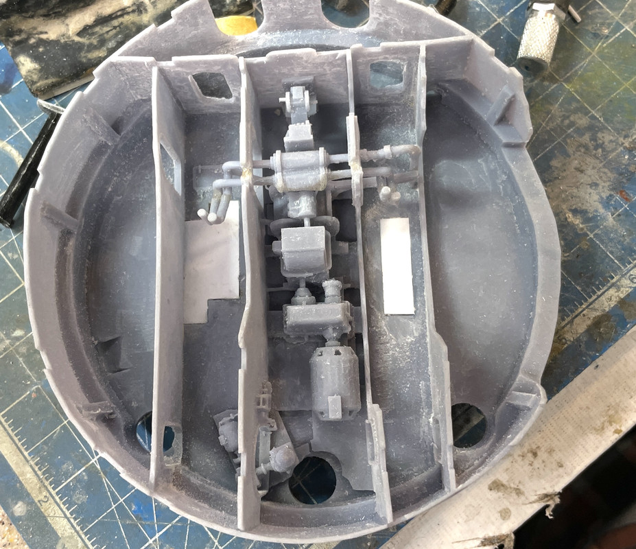
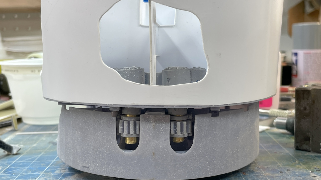
There are six, small bulkheads that fill the fore space where the training pinions are. They reinforce this critical bit of turret infrastructure. This took most of the afternoon. Each had to be hand measured and cut since there are some slight variations from side to side. What made it more challenging was the training pinions had to slip between nos. 2 & 3 and 4 & 5. When I first assembled them to look nice, they didn’t fit and I had to start ripping them out. Since it’s a styrene/UV Resin interface I had to use CA. This is good since the styrene has a so-so bond with the CA and I was able to rip stuff out (more than once), sand off the old CA and reglue until I got it right.

The Fit is quite tight. And then I had to put the pan deck on top with both pinions in their respective holes in the training gear heads, and then try and fit it together with the pinions not being cocked in one direction or another. This entailed more ripping out and refitting.
I finally got all six in and spaced so the pan deck worked. Then I had to go back and relieve all the slight misalignments with all these printed parts. I have reinforcing ribs under the pan deck with corresponding slots in the electric deck walls to accept them. I’m sure this is not prototypical, but I needed the ribs to reduce warpage of the big, flat pan deck base. They did the job, but they’re a pain in the butt to get to fit into the electric deck slots. I almost got it done when it was quitting time. My daughter and son in law were coming over for burgers. They’re now empty nesters with my youngest grandson starting as a freshman at Washington University of St. Louis in engineering and my oldest grandson entering his senior year at University of Illinois engineering.
Here’s the completed bulkhead scheme. As you can see by the above image, you realy can’t see any of it. What it did do was enable me to pull in the electric walls so they’re true vertical. That large cut out area for the pinions left the wall unstable and it was warping out a bit. I put some filler pieces in the middle bulkheads to hold their spacing since it was so critical for the pinion fit.
Once I get all the inpingement areas cleared out and get the pan deck to drop flat onto the electric deck, I will be done with the electric deck and it too is ready for paint. All the other apparatus will go in AFTER paint. Actually, lighting goes in before paint on all the decks. I mask the tiny LEDs, but the paint hides the surface mount copper conductive tape. There will be a lot of non-viewable areas on this deck also which will make it easy to get the lighting wiring down to the central column with terminates under the electric deck.
Assembly progress is moving along pretty well and it may not take as long as I was anticipating to get it built. We’ll see. There will always be more surprises.
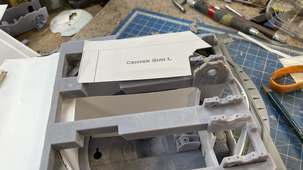
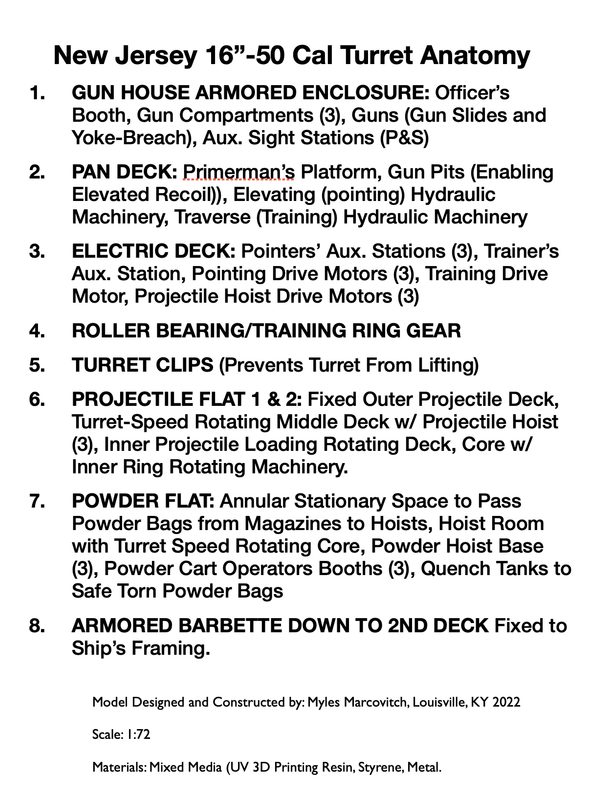
This is the illustration I’m going to include in the display along with the callout list. When I first developed the list I went into MUCH more detail, but realized it would bore people to death. Museum display designs usually have three levels of explanation. Level one is for the person who’s breezing through and just looks at things that catch their eye. The model does that. Level two is broad head type that gives a quick view of what’s what, and Level Three can actually get into paragrph text for those who want to stop and read. It was the level three depth that I’m still not sure about.
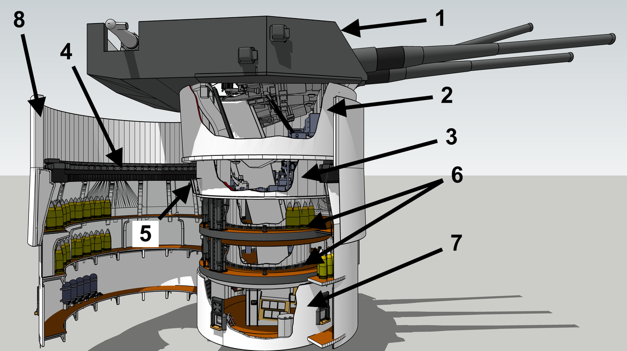
Here’s the text to go with the callouts. Should it be more? Less? Just right? Feedback is requested.
6 Likes
Pure model-making at its very best, this lurker’s breaking cover to say you’re doing an awesome job - the needle’s fallen off my Impressed meter ![]()
![]()
![]()
![]()
2 Likes
Thanks! You better get that meter fixed. I have a feeling it’s going to pinned again in the future.
I seemed to have missed an entire post from yesterday’s work. So I’m adding it here in front of today’s post. Both were pretty intensive sessions with lots of stuff to show.
First of all I edited the turret drawing to display the main deck and what lies above and below it. It was a suggestion by one of my many readers. It quickly tells the viewer just how much of this machine is below their feet.
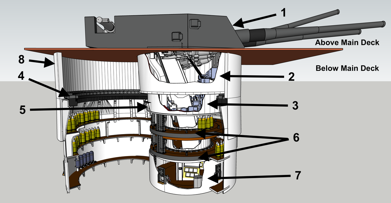
I made that correction suggested on the write up to spell out “Port and Starboard” and avoid acronyms.
I took two steps forward and two steps back yesterday. I finally got the pan deck and electric deck to mate. After chopping and cutting all kinds of places on the e-deck, and still having the rocking to and fro, like there was a high spot somewhere buried inside, I decided to do some lateral thinking and check the pan deck base. And of course it was bowed out. It was this prominent bow that was created the interference. I should have relized this earlier, since the inner surface was bellied and the partitions had gaps that I had to fill… a lot. I used a sanding drum on the Dremel and knocked down most of the bulge on the ribs and lo and behold, the two gets finally got it together!
Another view:
I’m really having deja vu here… I know I wrote all this stuff yesterday and have no idea why it doesn’t appear on any of the four forums to which I post. I do all the basic text here since Fine Scale has the most cumbersome photo upload, having to first load to a service and then to this site. All the other forums you can just drag an image from my files and drop it in.
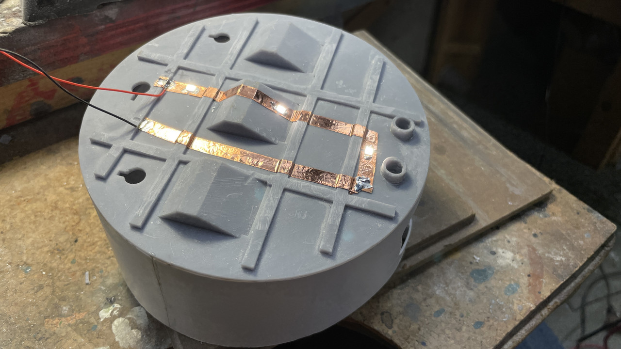
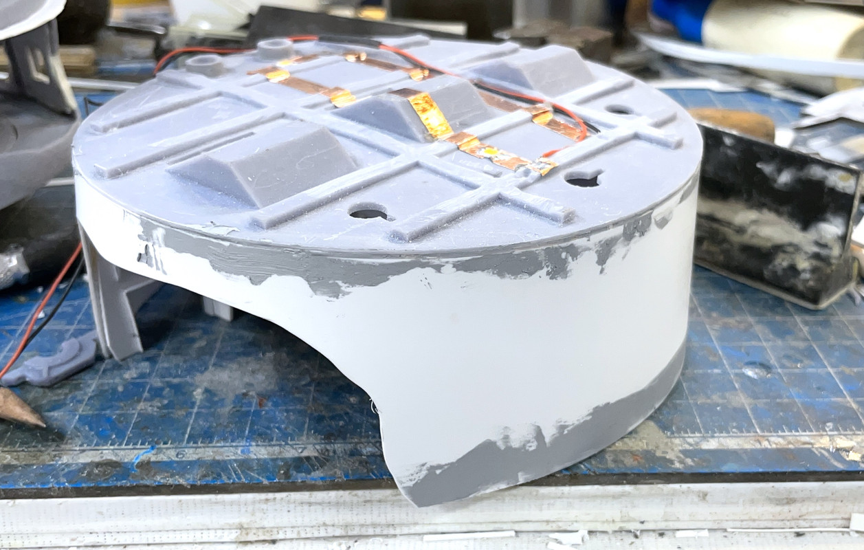
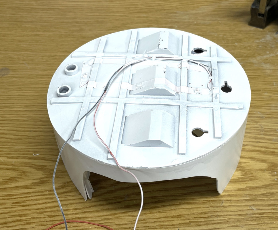
I wanted to get the pan deck ready for paint, but that required doing the electrical work first. I’m using surface mount warm white LEDs driven by CL2N3 LED driver chips. These little marvels cost about $0.25 a piece. You pump in anything direct current voltage from 5 to 90 and out pops 20 milliamps, just what LEDs love. No worry about current limiting resistors. You can string the LEDs in series limited only by the input voltage drops across each LED. Generally they drop about 3 VDC so you can run a 4-LED string with one CL2 on a 12VDC power source. I’m using a 12VDC LED power supply from Amazon that cost about $15. I’m using them all over the place on my model railroad and have another as my LED test rig.
The circuit consists of self-adhesive copper foil tape with the LEDs soldered into little 1mm gaps. I mark which end is positive (+) and negative (–), and ensure that I’m soldering them in correctly. The contact pads underneath the LED is tiny, and the + is much smaller than the –. I run the circuit in a loop where I want the light to be and cut the notches. I use the continous corners that I was taught in installing burglar alarms in the late 1970s when we were using adhesive lead foil on windows to sense breakage. You bend the tape back on itself, then turn it 90 degrees to form a triangle and stick it to itself. I pre-tin both sides of the gap with enough solder to puddle a bit when I place the LED over the gap and heat the solder next to it. You don’t heat the LED! They are temperature sensitve. I heat the foil next to it and let the solder, keep a little bit of pressure on the LED with a tweezers, and as soon as the solder melts and the LED drops into it, I take off the heat.
Here’s the illuminated circuit. BTW: If you get the polarity reversed it doesn’t damage the LED. They’re diodes and simply block currect in the opposite directoion. These puppies are very bright and I may have to attenuated them by painting something on the lens. They are much brighter than they appear here. The wire is 30awg silicone insulated stranded. There’s is very little current in this circuit and small wiring works perfectly.
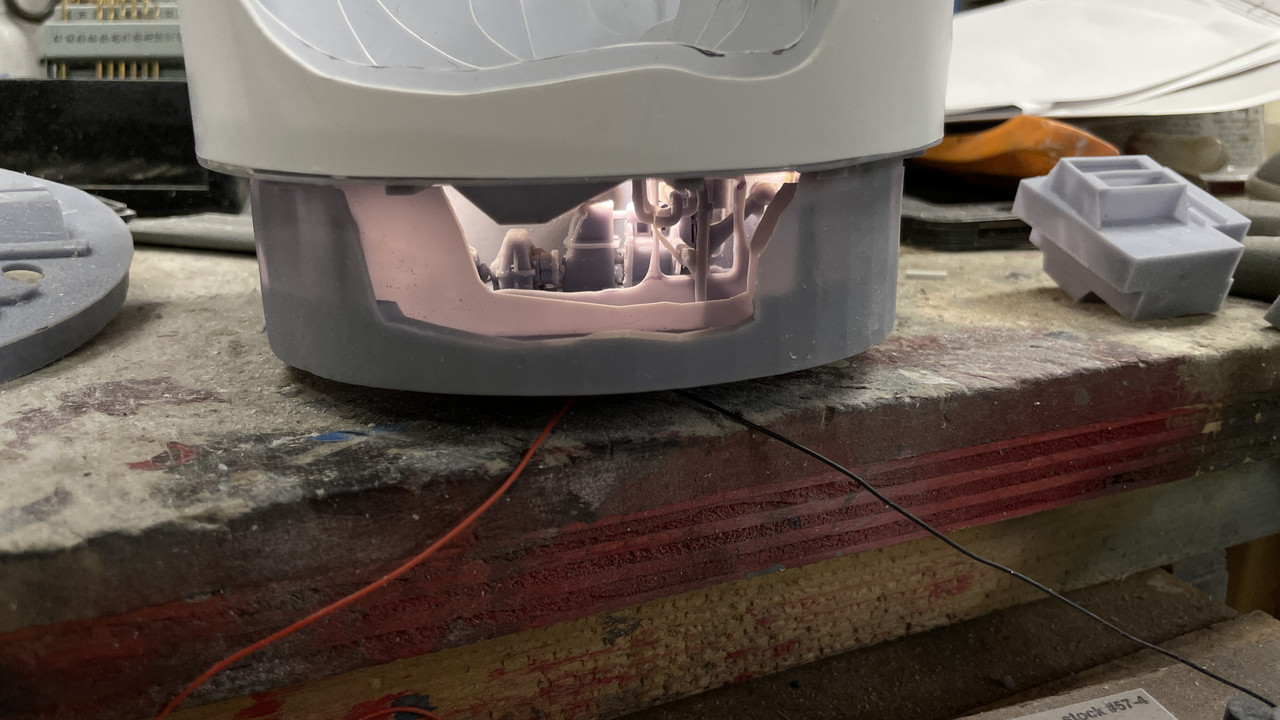
And here’s the e-deck lit. The translucency will be elimiated by the many coats of paint to follow. If it still shows up, I can back the panels with aluminum foil which totally blocks the light leakage. Half of this stuff will not be visible when the powder trunks go in.
Now to the ugly stuff.
I found that the boss on the bottom of the e-deck was completely off-center. The central hub was fine, but the surrounding circle was eccentric. I scribed a circle of what would be correct. I was going to attemp to repair it, but last night decided to print a corrected part which you will read about further down in today’s post. Don’t ask me how this could happen. I don’t have a clue. Every (or nearly every) circle I draw in SU is concentric with others. It’s very easy to do.
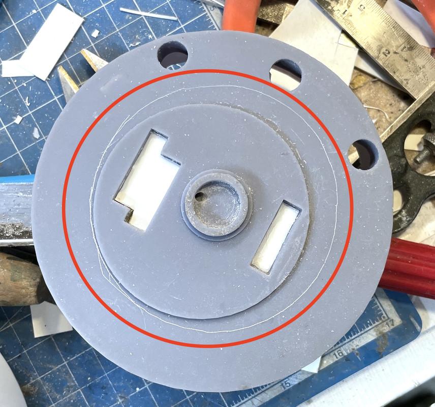
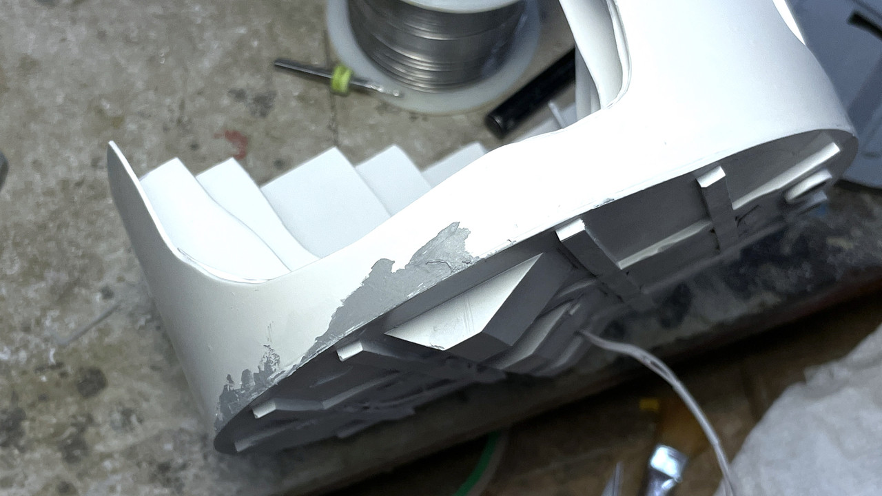
The other problem was the uneven wall height arround the pan deck perimeter. This had to be fixed. I used a surface gauge and scribed a line from the lowest wall point around the entire circumference. I then used an abrasive wheel in the Dremel and removed anything that was higher. It was a scary bit and could have wrecked the whole deal, but didn’t. Today I trimmed all the rest of the stuff that was sticking up. I don’t know what this amount of material removal is going to do with the final constuction. In actual practice the gun’s recoil would possibly be too long for the ceiling height at full elevation. But I’m not elevating that high AND my guns can’t fire and therefore can’t recoil. And it may be a benefit. I may have made the elevating scews too short, but this extra 3/16" could be all I need to have them comfortably fit into the tilting boxes.
Today’s post:
Still wrestling with the real world versus the 3D designed world. It’s a shock when I find my brilliantly designed things don’t quite translate into the solid objects of which this world is made. Case in point…
I decided to reprint the electric deck and the insert. There were aspects of both that could be improved and I had already drawn a later version of each. The big print worked overnight so it was waiting for me this morning. It wasn’t bad although again it had large ribs in places that weren’t on the design and again, I was able to surgically remove them without damaging what was there. The bottom of this new part did not have that off-center boss problem like the previous one did. In fact, it had no boss at all. Furthermore, to add to the fun, the center lug that sits on top of the central column, was not physically attached in the drawing and printed anywhere as a separate part. It was so well supported it just print right where it was, but fell off when I removed the support. I glued it back on with Gel CA.
I thought it was good that it didn’t have a boss, but then found that when I assembled it with the projectile flat that lies below and added the projectile hoists, the electric deck was sitting about 0.080" above the projectile deck’s inner drum held up by the projectile hoists. It NEEDED THE BOSS!
I made the boss out of a laminate of two pieces of 0.040" styrene, and attached it using 3M transfer adhesive tape. This stuff is contact cement that comes on a roll. I can be amazingly strong when applied to clean surfaces. The spacing is now corrected.
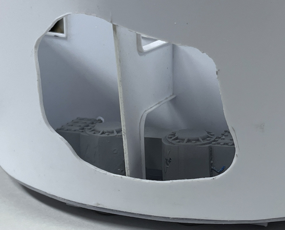
I spend more time on the projectile deck centers starting to get the powder hoists trunks final fit for installation. i also chose to install the other apparatus in these inner spaces. Visibility is terrible inside due to the vision blocks set up by the powder trunks. I suppose I could hack some material off of them to show what’s behind, but I’m not inclined to do so.
I finished up leveling the wall tops of the pan deck and got it ready for paint by finish sanding and filling the outer surface. I double-checked the drawing and flat pattern created by the software to see if the errors were there. They were not! The entire length of the pattern was parallel. What I think happened were errors crept in during the bending and glue up. It’s a conical shape and depending on how the final joining was made, it could have changed the height of the sides in places.
After sanding I went around and filled any gaps in the styrene-resin interface with Tamiya fine filler.
I took the pan deck outside and rattle-can sprayed it with Tamiya White Primer.
And after using Molotow Liquid Mask, I did the bottom.
I put a final coat of filler on a few missed spots and will sand that in tomorrow’s session.
I’m going to paint the wall gloss white, the floor will be linoleum brown, with the apparatus painted medium gray. Ladders and projectile hoist trunks will be white.
Next up was the E-deck reprint. This print, besides missing the bottom boss, had the front bulkheads printed in place and they looked good (except for the middle piece of the front wall and two of the arms breaking off during cleaning). There was just one small problem. The pinion gears and their housings couldn’t go into the space. Once in the space they would possible work, but I couldn’t get them in there.
They fit in the drawing! That’s becasuse, they aren’t real and could move through the parts that were in the way into the space where they did fit.

It is essential that the pinions drop straight down into the space without a lot of wrangling. It’s part of the entire pan deck structure and that’s hard enough to get into place without having to hassle with the gears. So I took the router and removed the four inner bulkheads. I left the outer two in place. I will scratch-build them as I did with the last version, out of styrene spaced wide enough so the pinions fit
Re: the middle appratus print: The print was perfect except for a mal-formed wall and projectile hoist power unit that sits across one of the bulkhead openings. I will surgically remove the bad stuff and transplant a good from another print I have. NEVER EVER THROW AWAY REJECTS UNTIL YOU’RE ABSOLUTELY SURE YOU WON’T NEED THEM!
Tomorrow will be the last work session for over two weeks due to the Hawaii trip. I will still have access to the forums so I can respond to comments.
6 Likes
Last short work session before vacation (now… really…when retired you don’t “really” need a vacation. Everyday is a vacation). I finish sanded the outer walls of the pan deck and powder flat. Continued mounting stuff into the projectile flats, and reprinted successfully that complicated mid-section of the electric deck.
I woke up thinking that why should I spend the effort to cobble together a good part when I know exactly what failed in the print and know exactly why it failed. It took 10 minutes to add and modify the supports so that area wouldn’t fail. I put it on the machine in the morning, did my exercises and by 3:30 p.m., the part was done.
These two images show the failure and the success.
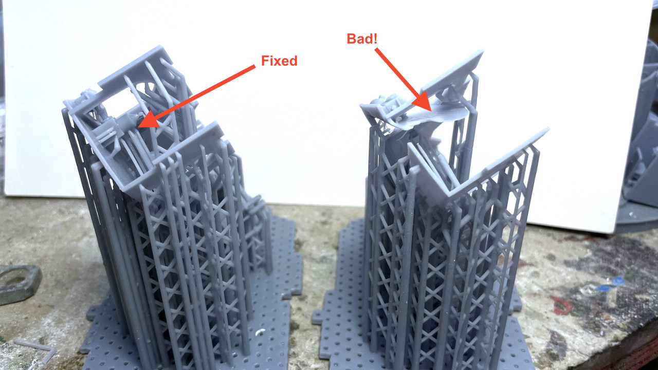
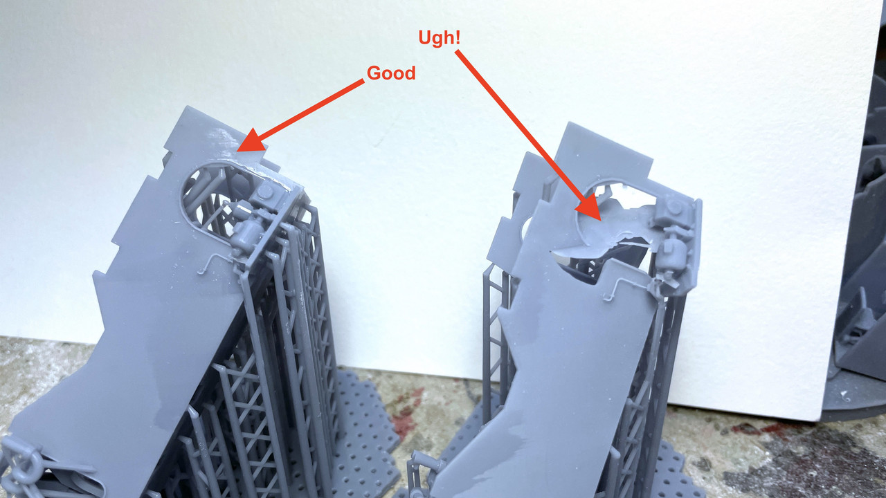
It was actually the good kind of failure: nothing was separated from the part and stuck to the FEP.
After support removal and a couple spots needing some Bondic, this is what it looks like. It only took four iterations to get this one right. it was a complicated part that stretched the envelope of a single part print.
When we return from the trip, I will grind off all the support scars. This version has the corrected pipe positioning to align with the training B-end one deck above.
And with that I see y’all in a couple of weeks.
8 Likes
Aloha
Aloha! (that word and Moholo) is the extent of my Hawaian vocabularly after spending 12 days in paradise. It lived up to its expectataions and besides spending a small fortune, we really did Maui. We don’t do serious hiking, paragliding, jetskiing or any of that ‘rough’ stuff, but we did do a lot of fabulous restaurants, visited a distillery, a winery, a glass factory, two botanical gardens, aquarium and walked on beach trails that gave views like this…
and this… This was outside our hotel balcony.

Maui was created over a million years by two volcanoes. Actully the five islands that make up Maui’s neighborhood were all one island many years ago and between subsidence and errosion, the connecting land bridges submerged. It’s why the channel between Maui, Lanai, Molokai, Kaho’alawe and the Molokini Crater is so shallow. The West Mountains are the remnants of a volcano that last erupted about 1,000,000 years ago, but the other, a 10,000 foot monster, Haleakala, erupted just 200 years ago, so it’s only “mostly dead”. The West Mountains, like the San Franscisco peaks at Flagstaff, AZ was once a huge mountain, but has broken down and erroded to a series of interesting peaks.
The best part of the trip was biting the bullet and renting cabanas during our four beach days. I am a true white man… I mean I am pitifully white, and sunburn just by imaging the sun in my head. Modern sun screen helps, but a cabana helped a whole lot more and made staying down by the sea for hours and hours much more relaxing. This was a view from our cabana watching the idiots going around in circles on jet skis and paying a fortune to do it. For the exhorbatent price of the cabana, they provided us with cold water and fresh fruit (including Maui Gold Pineapple).
We flew Louisville-Dallas-Maui-Dallas-Louisvile. The L’ville leg was on regional jets, but the Maui run was on an American 787-900. It was our first time on this plane and we flew Premium Economy. Premium Economy exceeded our expectations and seemed very much like business class (which I flew many time 20 years ago back and forth to Germany). I would recommend. It costs more than coach, but it’s worth it. Five years ago, we flew First Class on a United 777 and it was definitely NOT worth it.
Now onto modeling. Finally got back in the shop and I hate to say it, but it felt great! I picked up where I left off; fitting the center section into the newly printed electric deck and getting the rest of it ready for paint. The was very little clean up on the middle part to make it work. I had to open up the hole for the projectile hoist trunk, and sand off some divots, but that was it.
I then spent time re-creating those little bulkheads on the forward part of the e-Deck. So little of these things is visible from the enclosed front that it’s really not worth the effort, but you know… AWS. The pinions now fit this new space without binding. I also enlarged the semi-cicular pinion openings since the teeth were contacting the walls and weren’t able to rotate. I want them to rotate so they can seat properly on the large ring gear.
The e-deck is now ready to receive all the apparatus either painted or un-painted… haven’t decided yet. Assembly will continue more quickly now that everything’s ready to go (except all those outer shells).
6 Likes