Thank you. Re: getting figures, I’m terrible at them.
Another short session, but I did get the modified gun house hatches printed and installed. They are now fully opened, pinned with newly acquired 0.015" phos-bronze rod. They should survive a bit longer now that they’re not sticking out so far to constantly getting whacked while I’m doing something else. I also reprinted more foot rungs to replace the last broken ones. I printed nut plates to replace the crude ones I had previously installed. I have to add just two more rungs, barring breaking any more. So it’s now ready for paint.
I’m starting work on writing a book entitled “3D Design and Printing for Model Makers”. After four years and thousands of parts produced with lots of success and solving lots of problems, I have a lot to write about.
While there are copious ammounts of articles, books and videos on 3D printing, I’m finding a gap in instructional material for model makers. When you look at what’s currently available, much of it covers printing monsters and characters in the fantasy realm. Printing characters can teach about machine setup and supports placement, but lacks consideration for designing parts that must conform to rigid design and printing regarding scale and assembly of parts that form precise assemblies.
I intend to close that gap. My latest Apple version of Pages includes book writing templates. Apple also provides free uploading of books to Apple eBooks. They take a cut of the sale proceeds. I can live with that. They don’t provide free marketing. For that, I’m going to need some help.
I also will need feedback for folks regarding the soundness of this endeavor.
6 Likes
I’m thinking about modeling one of the Iowa Class engine rooms. These, like the turrets, generally are not visited much and a good model would help explain what’s going on there. When I proposed this to Ryan, his response was, “WOW!” So I’m assuming he’s okay with it. I would need to get a powerful broad-range 3D scanner to grab some of the shapes of the machinery. I don’t know what reference material is available out there. Meanwhile, I have to still figure out how to do the lower deck work for this project. Right now I have the compartments drawn, but don’t have the cutaway access so you can see inside.
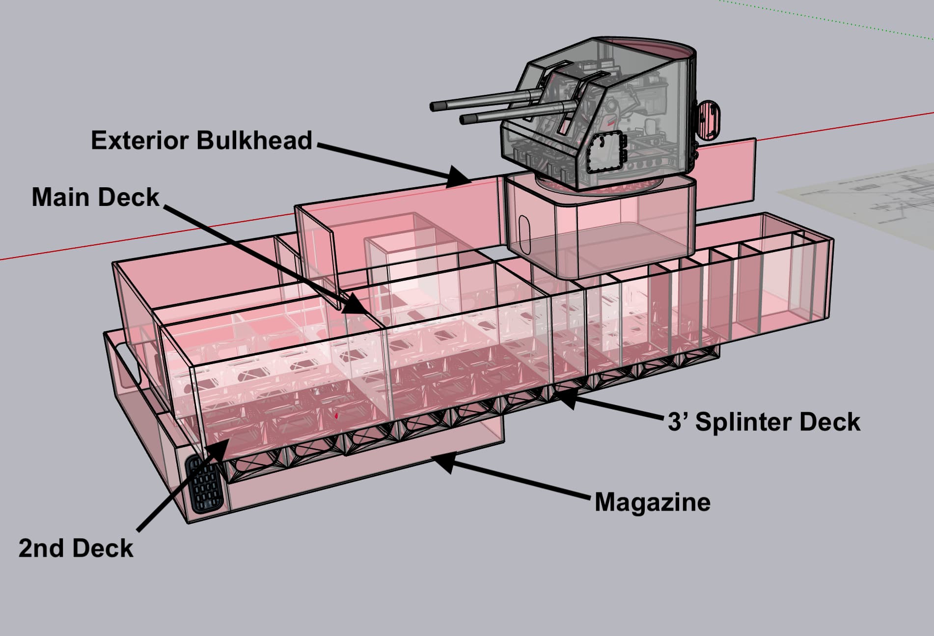
The projectile and powder trunks wend their way up from the magazine into the upper handling room. They cut through the splinter and 2nd decks and not in a straight line.
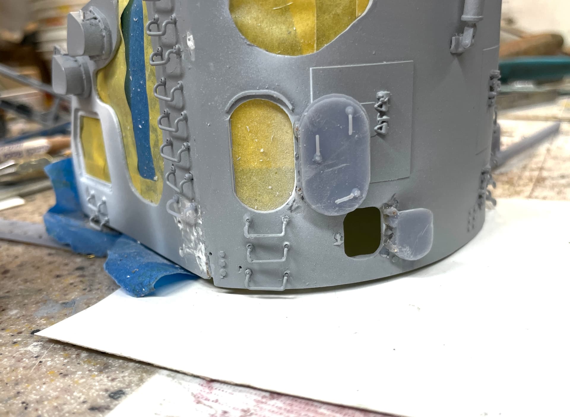
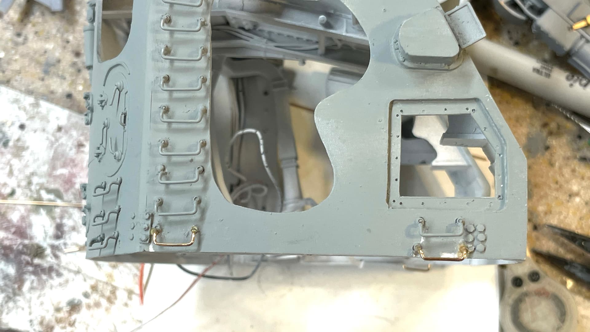
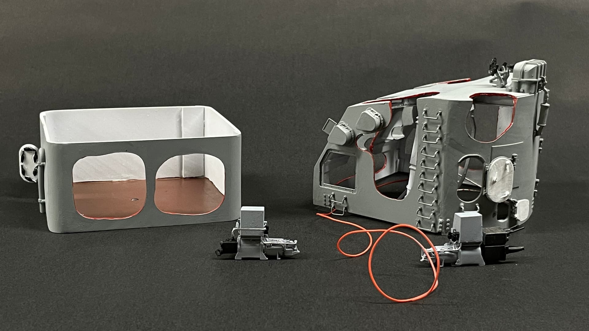
Today I got the haze gray painted on the parts with exterior-facing surfaces. I fixed the ladder rungs I broke last time, and proceeded to break another one. I found an error in the drawing that could have led to the apparent weakness of the part. I’ve corrected the drawing and with reprint one more time to have to fix any more that broke. The broken one is obvious in this picture.
The masking worked well and no haze gray got inside. I pulled the masks of the LEDs so they are now ready for use.
And then I continued to add painted details.
I have more detail painting to do, but gun house assembly is just days away. I need to get some fresh backdrop paper to take really good photos. These will be used in the AV presentation that will accompany the model on display. I have to find out what these digital picture framws need regarding formating. This way, folks will be able to see all the parts even when they’re obscured on the finished model.
8 Likes
Another short session.
I redrew the ladder rungs to fix yet another slightly gimpy engineering aspect. I print them on their own little bases instead of on a long stick. This reduced print time from 6 hours to a little over an hour. I only post-cured them for four minutes, which could still be too long. I wanted to reduce their tendency to become brittle.
They worked okay. And then I noticed another broken one on the other side. I’ll fix that one tomorrow. These things are turning out to be the most annoying aspect of this entire project (so far).
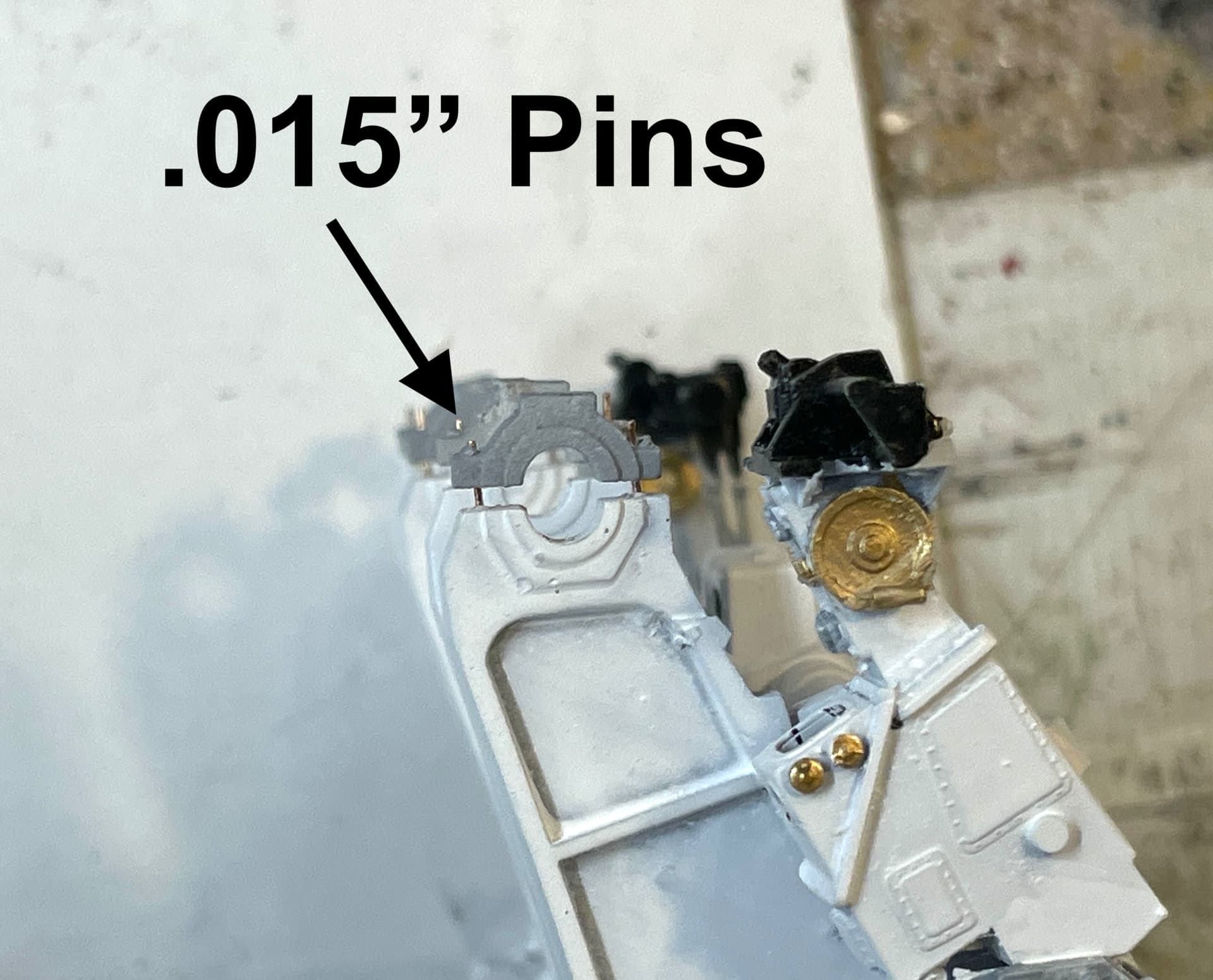
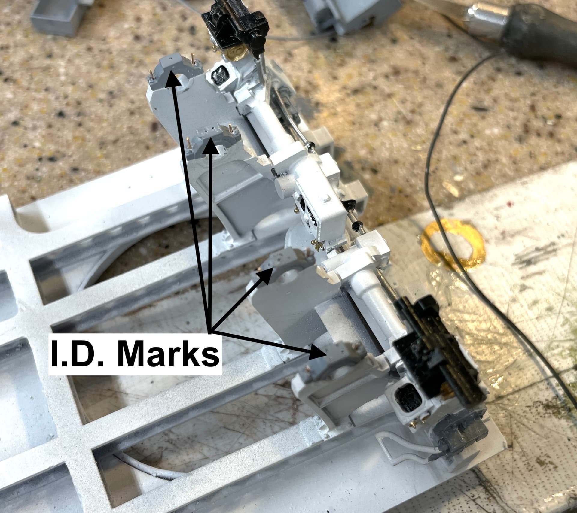
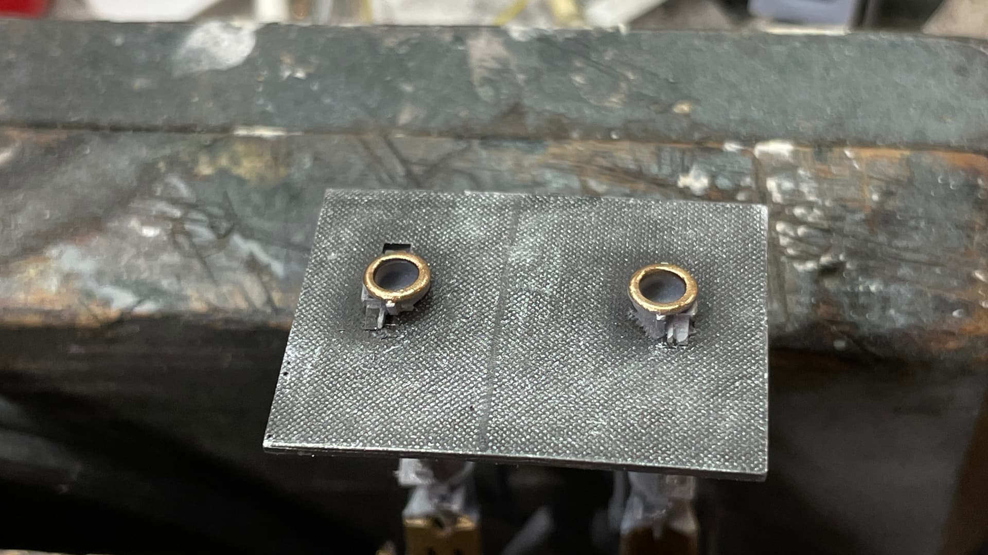
I also prepared the trunnion caps. I wanted to wire them and I really couldn’t wait until more work was done on the base for fear of breaking something. I’m using the 0.015" rod and drills. This is a new size for me. I’d been focusing on .010, .020 and .032. I’ve now added .015 and .025. These intermediate sizes can be useful. And I drilled 16 holes and DIDN’T BREAK A DRILL. I think that’s a record for me.
Since each cap was a custom drilling job, I had to mark the caps so they would go back in the proper place. I drilled some more holes to mark their place. This should help. Not shown is the coat of white paint I added to them. I will have to remove the paint on the pin extensions or they won’t fit back through the holes when I take them off to install the guns.
My wife has her last post-infusion bloodwork tomorrow morning, and if the weather’s nice, we’ll take a walk, but I should have some more time to work too.
6 Likes
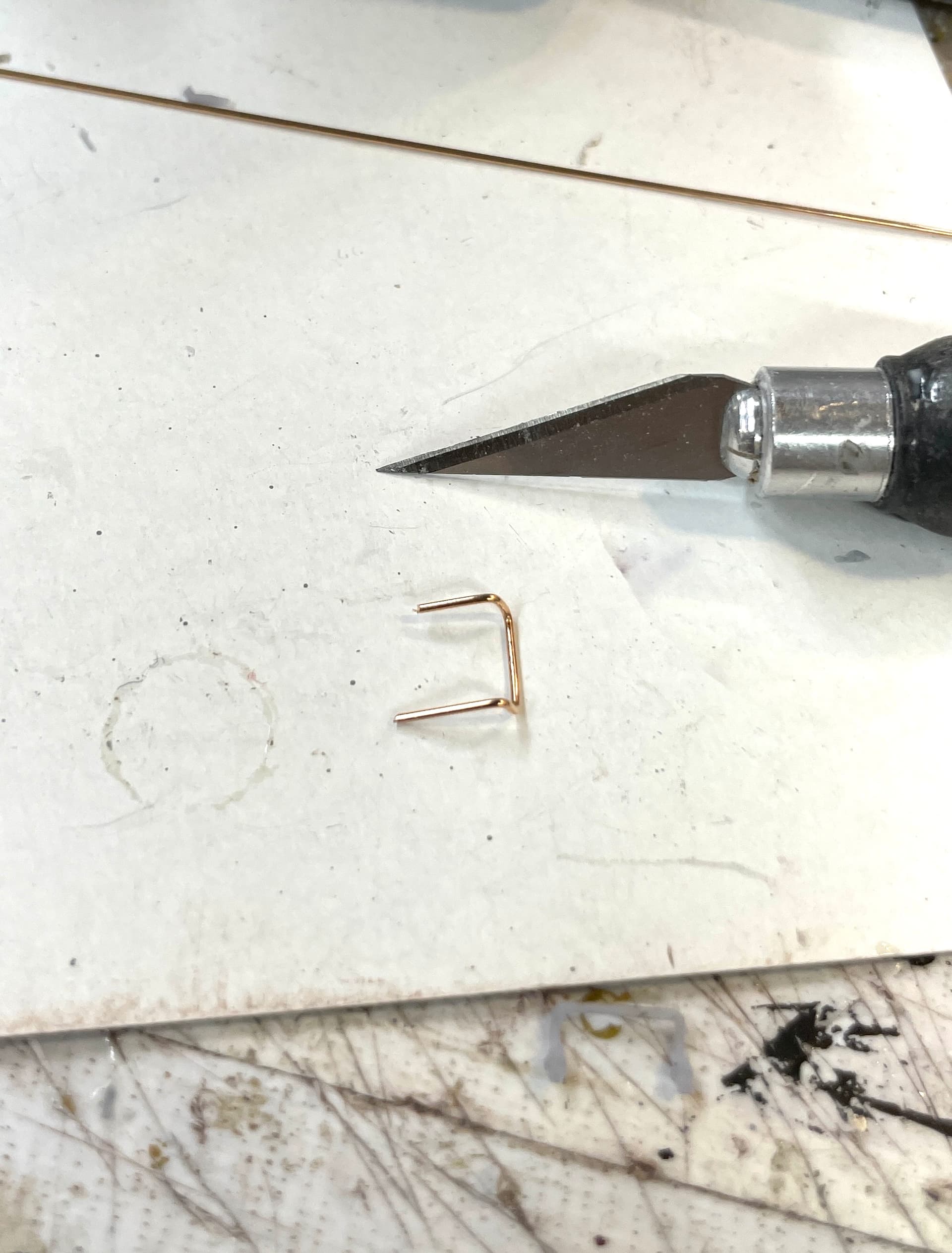
After finding more broken foot rungs, I decided “enough is enough!” and started making them out of metal. Turns out my printed ones have a .025" cross section and I have phos-bronze wire in that diameter. I measured the rung’s width on my 45 year-old Channellock needle nosed pliers. I placed some masking tape at the point on the tapered plier nose so I could replicate the width. Once you get ladder tread measure, the rest is straight forward.
The hardest part was preparing the area to re-drill it for the rung. I had to fill some spots with Bondic. After installation they looked acceptable. When painted they even worked better. Should have gone this route in the first place.
Using bare metal foil matte aluminum, I covered the unpainted gun slides and then the curved gun shield facing. I like how this came out. I set the grain to go fore and aft on the slides which is how it looks for real. I may put an overcoat of some transparent color to look like lubricant.
I also painted all the floor plating. First with Tamiya dark iron, and then dry brush some “real metal” from AK Interactive. Now I have proof that the diamond plate texture actually is there and if you look really, really closely, you’ll see that the diamond pattern is correct. This is the gun house exit point for the powder cartridges.
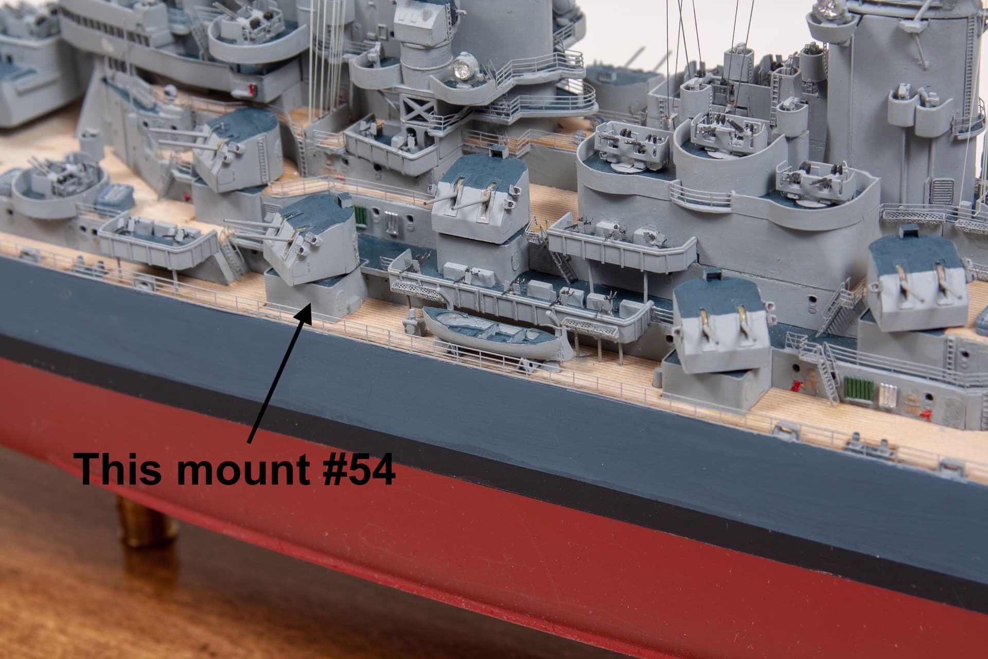
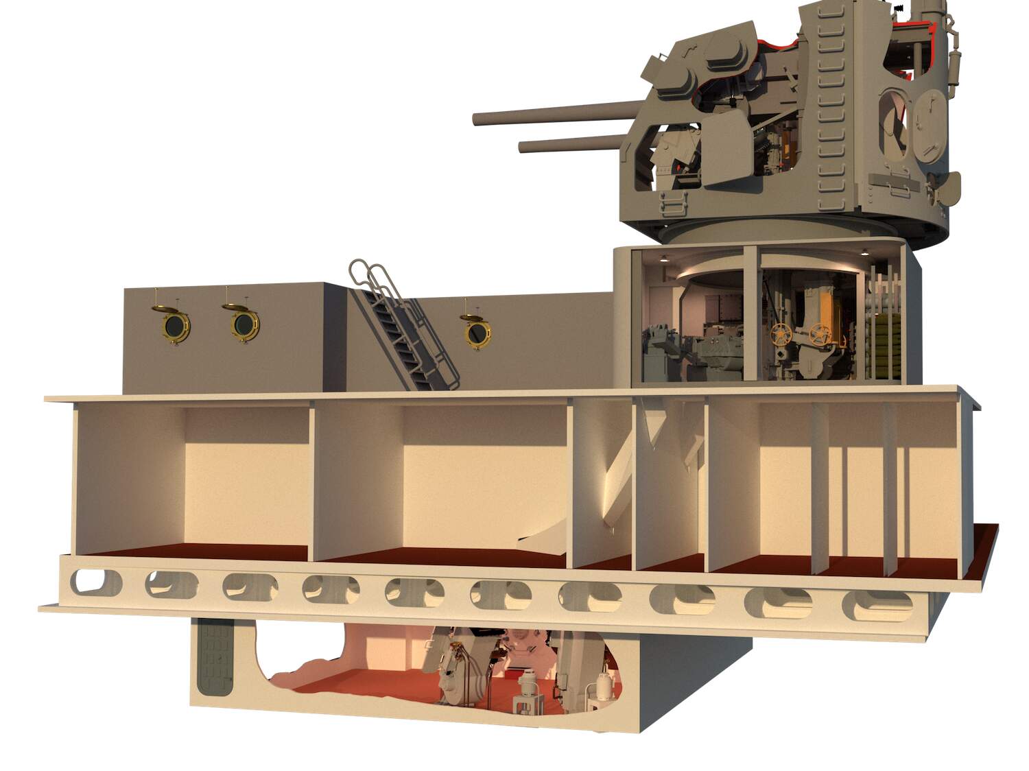
I have to paint the UHR’s floor which I believe was linoleum, and then the top works are ready for assembly. I’m still working how to do the rest of the model. I’m waiting for an epipheny to steer me in the right direction. For example: how much of the ship’s superstructure do I need to add around the gun house? You can see in this image of my Missori model that, there’s a lot going on around it, but does it add to the understanding of what I’m trying to convey?
Onward and upward… BTW: My wife’s bloodwork was all good. She doesn’t need to see the doc until July.
9 Likes
Lots of trim painting, fixing more rungs (one more to go), and installed my new black backdrop paper. What a difference it makes in picture taking. With the dark background the iPhone is not underexosing the subject while trying to adapt to the background.
I’m about one day away from assembling the upper works. I’ve been thinking about making the ship structure out of clear acrylic without any details, just to show it’s there. Still have to think about it.
I am really pleased with the photo. I’m going to have to take a lot of pictures of the finished parts and sub-assemblies for use with the AV presentation. Having this look will really help. You can’t see the red edges of the cutouts easily in this image, but they’re there.
9 Likes
Thanks Tom!
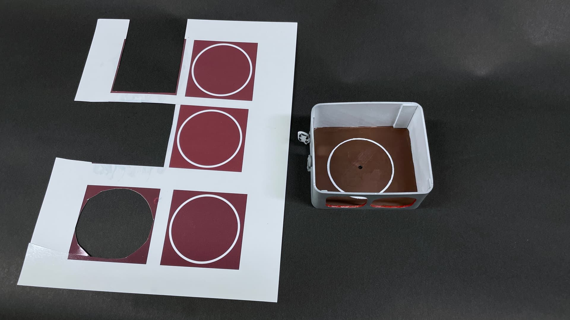
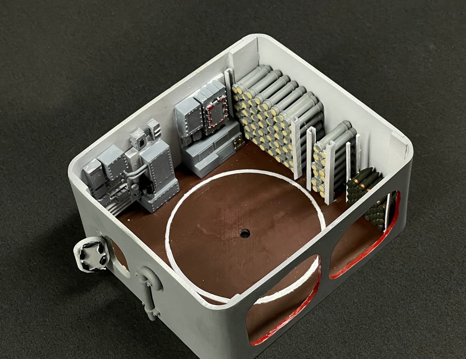
The floor of the UHR has a white line demarking the working circle of the loaders and the upper hoists. It’s noted as 117" diameter. Remember, unlike the big guns where part of the room rotates with the guns to keep everything in line, in the 5" system, only the hoists themselves rotate with the turret above. The room stays put. That circle tells folks that people are moving around quickly to keep up with the turret’s rotation.
I first attempted to do it as a decal. I was trying to match the linoleum brown color by memory, but as we all know, color memory is iffy. Since I didn’t get the color right, plan B was to trim out the decal and apply it as a ring. That didn’t work so well. The decal was very squirrely and was a mess. I resorted to masking the floor and cutting the circle with a dividers with on arm having a chisel edge which I ground to do this particular kind of task.
It ain’t perfect, but the viewing angle is so shallow that it will look just fine. On Monday I’m going to start assembling and photographing.
6 Likes
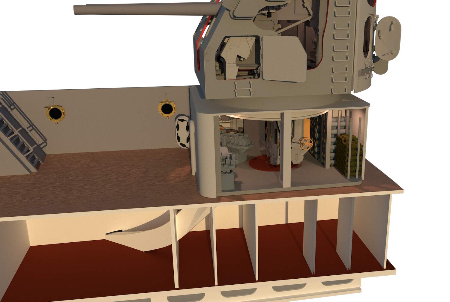
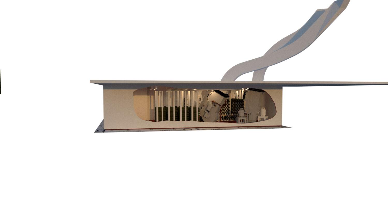
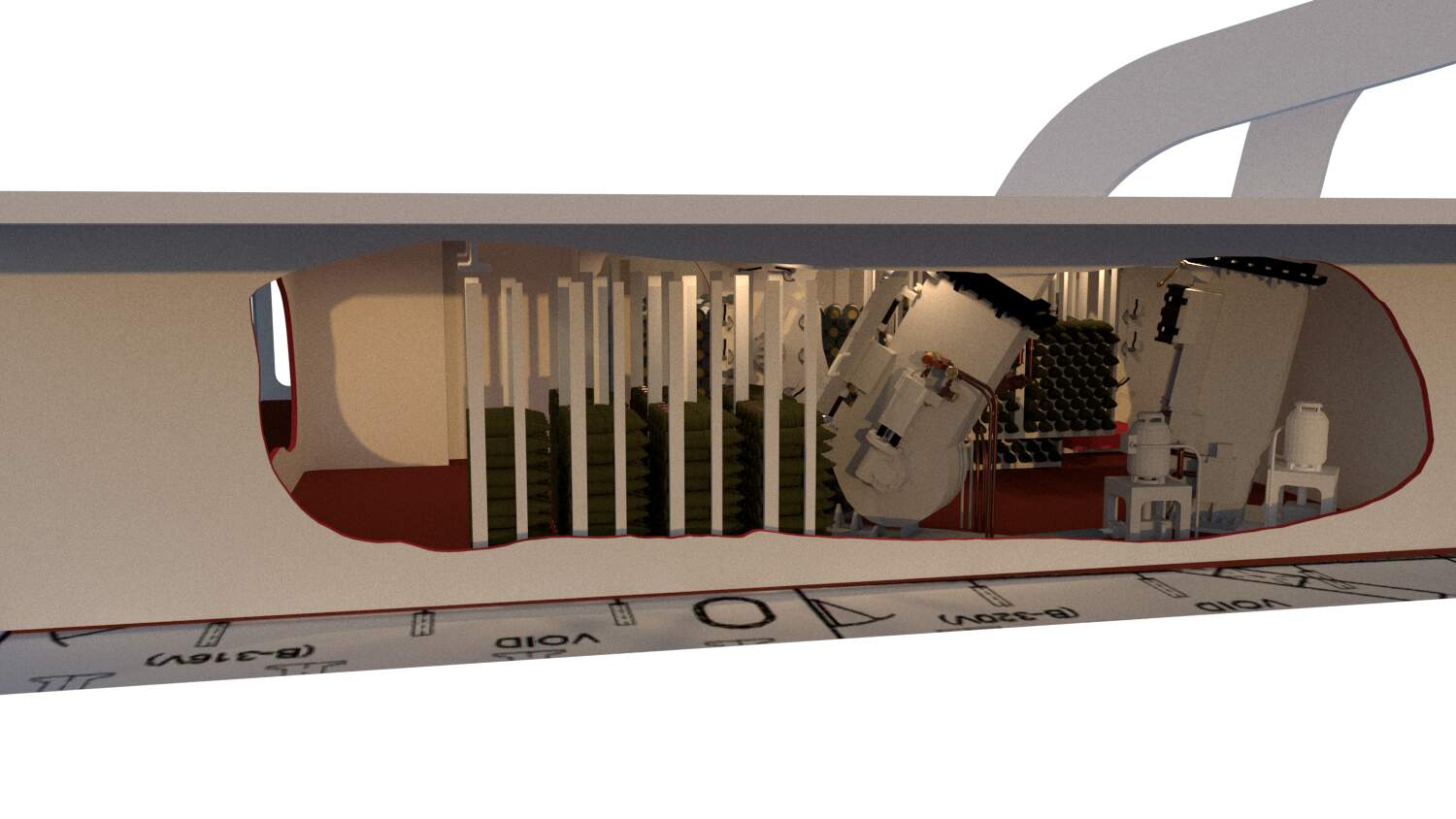
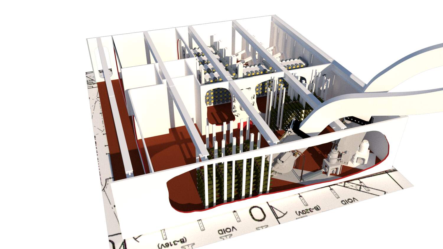
I think I have the final configuration done. I was noodling using clear acrylic, but dropped the idea since it’s so hard to work with. I’m going to use styrene and do cutaways. Here’s what it’s going to look like. Took two days to figure out the runs for the powder and projectile trunks.
I’m not detailing any of the intervening offices in the second deck. They’re not the subject of the model and would detract from it. They’re only there to show that the magazine is some distance away and not right below.
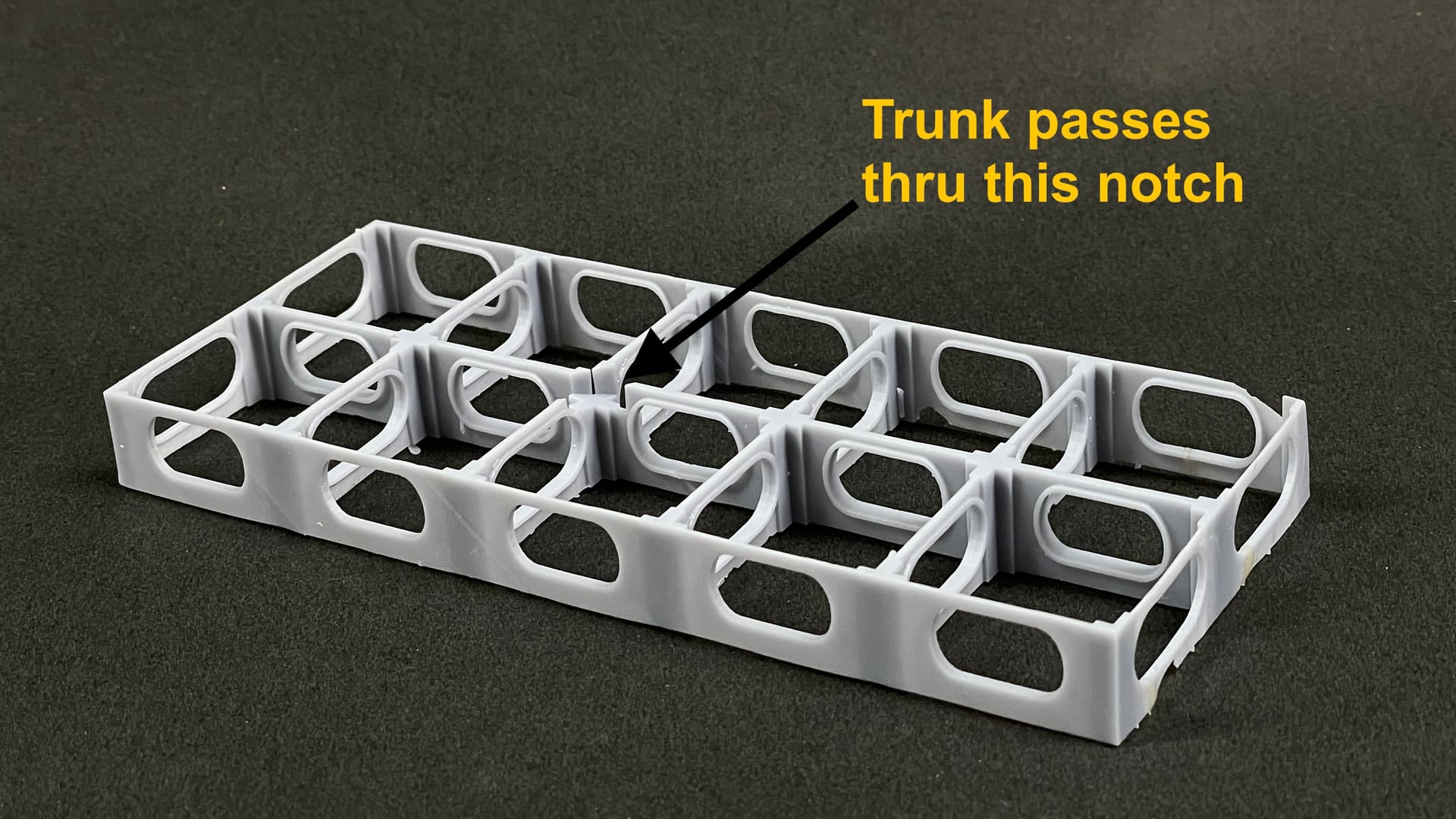
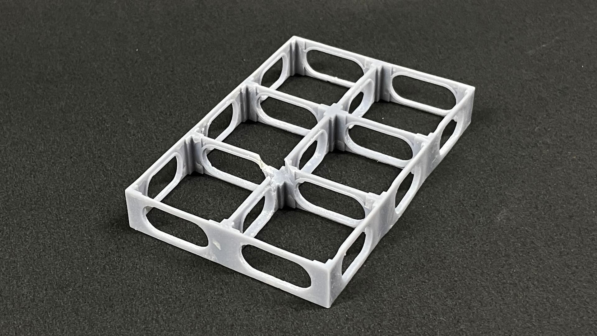
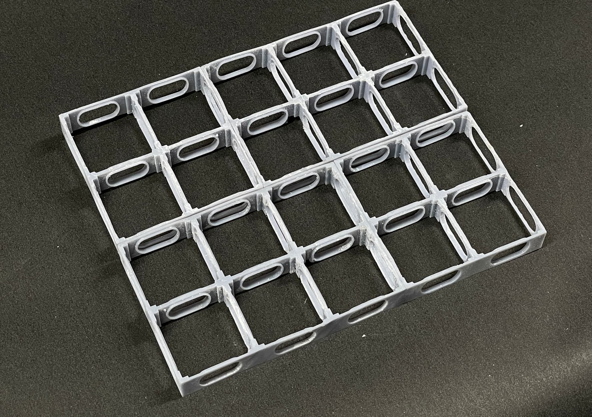
I drew the splinter deck scheme and will do it in modules, just enough to fill the space of the display. the splnter decks runs almost the entire length of the armored citidal in the ship.
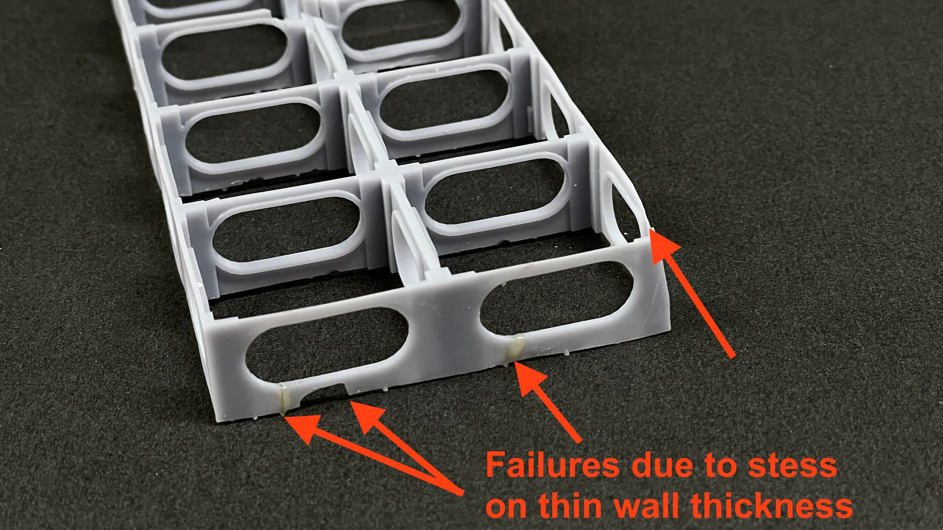
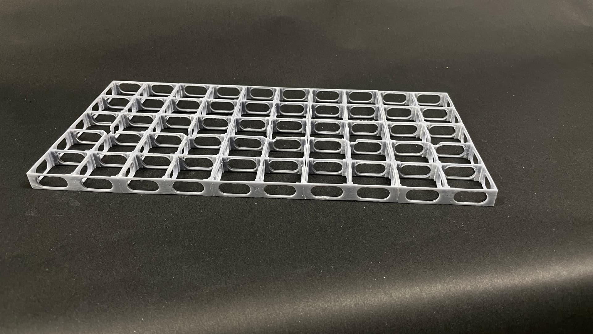
My print was at the extremes of my machine. I did make the wall thickness a bit narrow. While the print was not a complete failure, I’ve made changes in the object and in the its support scheme.
It will take five of these modules to make the splinter deck section I’m modeiling. I thickened the exterior walls and split it to print in two parts. That has a side benefit. It reduced print time by 3 hours due to having less height in the machine.
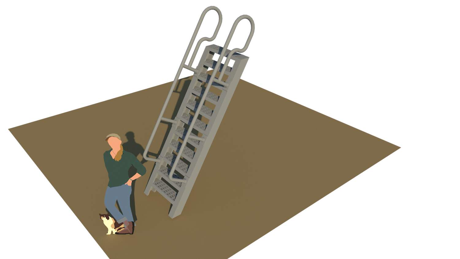
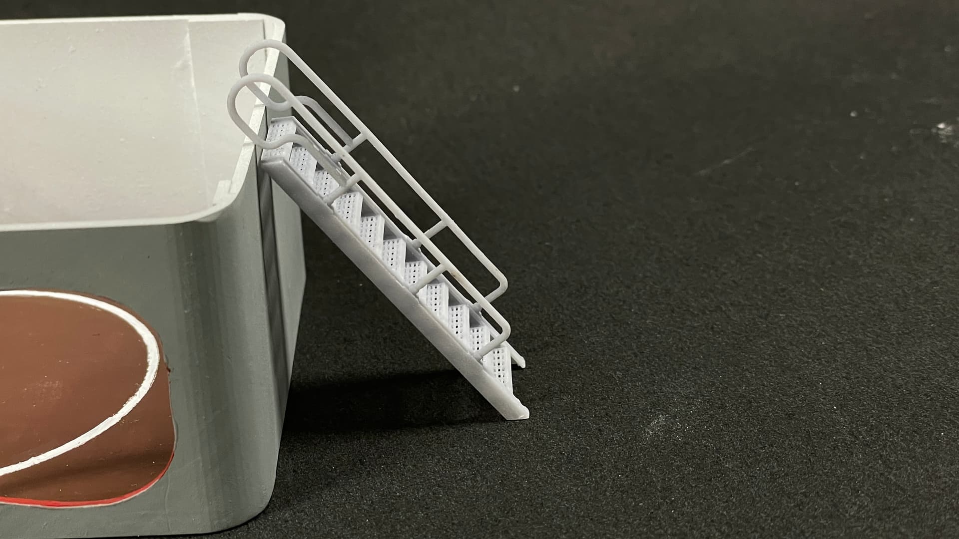
I also drew and am printing right now, the single US Navy inclined ladder that is near this particular mount on the real ship. My research found a lot of variations of these and many on the real ships have been replaced so they’re not WW2 versions either. I took some license.
I perforated the steps and we’ll see how that prints. It’s pretty small in O’scale, but it printed the diamond plate flooring so you don’t know unless you try.
6 Likes
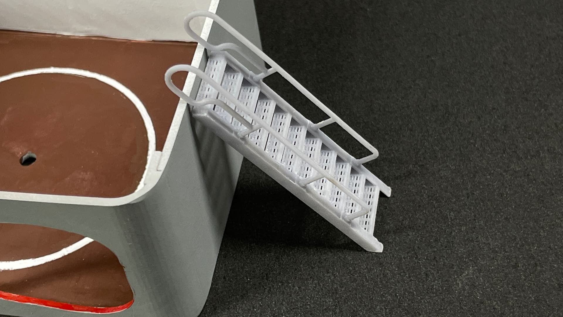
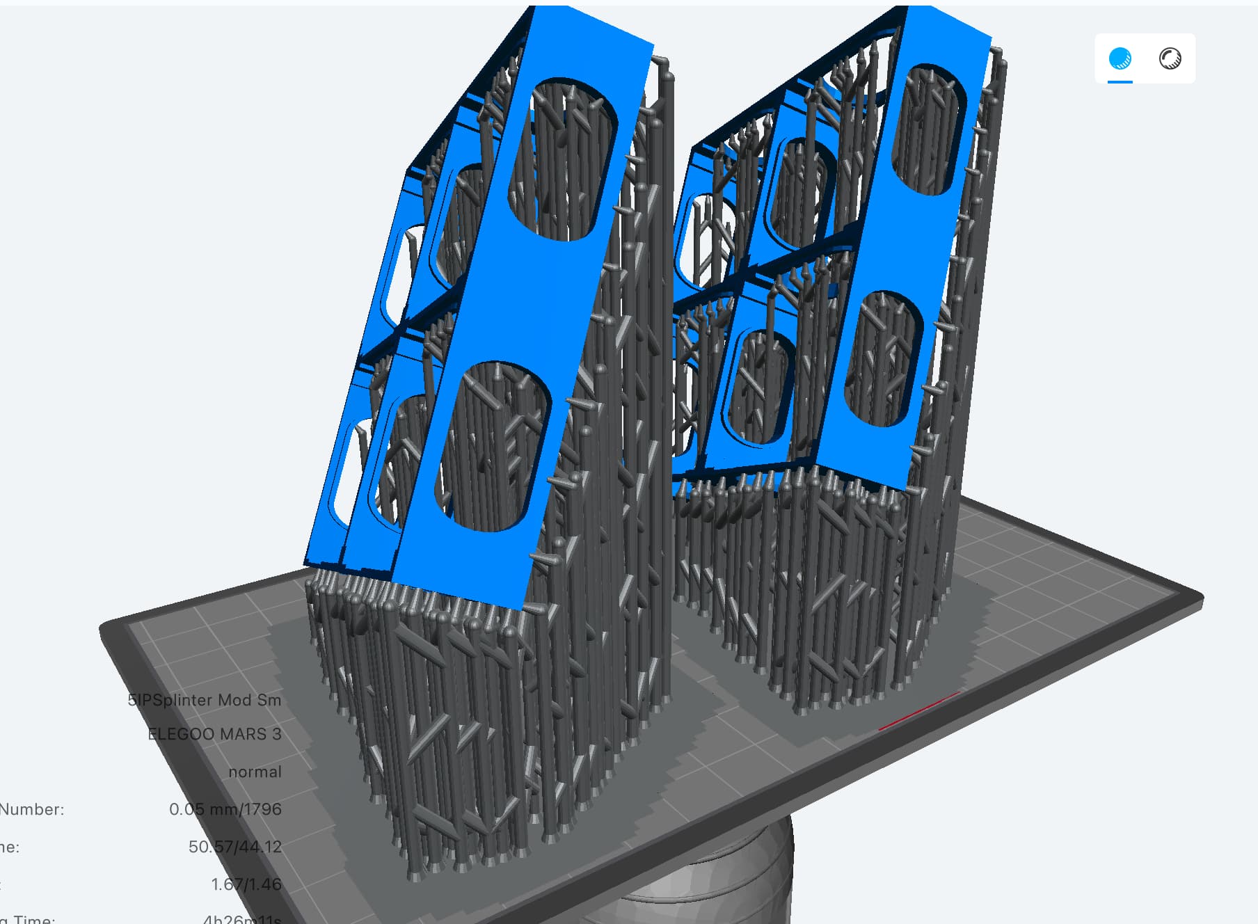
The ladder print came out great! All the perforations in the treads resolved without difficulty. My reprint of the splinter deck modules was so lucky. Something very weird happened in the Slicer (new version of ChiTuBox recently downloaded). On the larger modules, everything worked pretty well. On the smaller one all of my custom-added supports were not in contact with the object. They were just floating in space relegating most of the print to the trash bin. I don’t know how this happened. Never had it happen before. It’s like the object moved leaving the supports behind. They were all offset by the same amount. I am reprinting the small module and then will do the combined one again.
I thickened the railings so they would print well.
The larger splinter deck module printed well with the changes I made to wall thickness. The small modules (2) are being printed again as I write this.
I spent the rest of the sessoin doing final detail painting. Just about done that. I’ll take pictures later. I’m going to start doing the formal layout of the ship structure. I also have to design and print the rest of the racks and panels that go into the lower handling room and the magazine proper. The end is not as far away as it was before, but it’s still away.
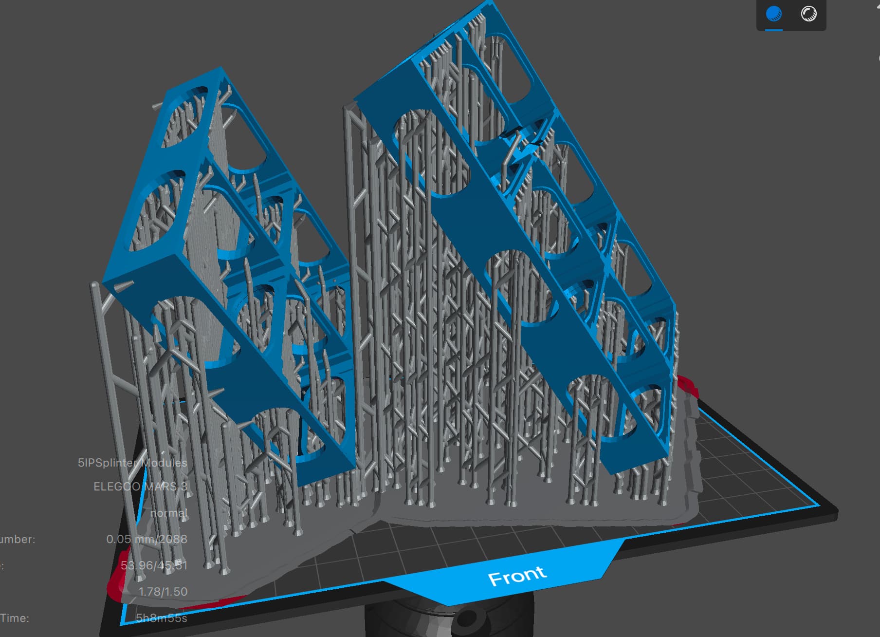
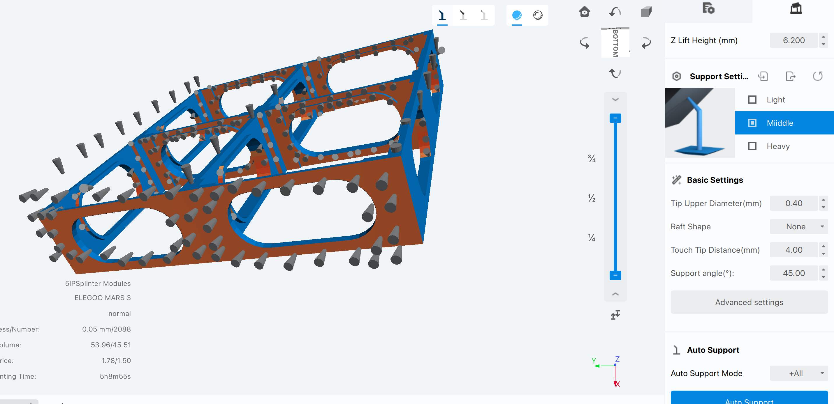
Here’s what that crazy sliced drawing looked like. I didn’t pick up this mess before putting it on the machine. Normally, when you position a support, it won’t stick unless it’s positioned on the part’s surface.
I re-opened the slice file and edited all those supports. I deleted all the floaters and then re-added them. You can see in this screen print that all the supports ARE in contact with the object.
It’s a constant learning experience. Meanwhile, I writing a book about it.
6 Likes
Very nice. Its going to look even more impressive we now have idea about how and what the turret will sit on. Love those steps btw, lovely detailing.
That ladder looks fantastic !
Thanks guys!
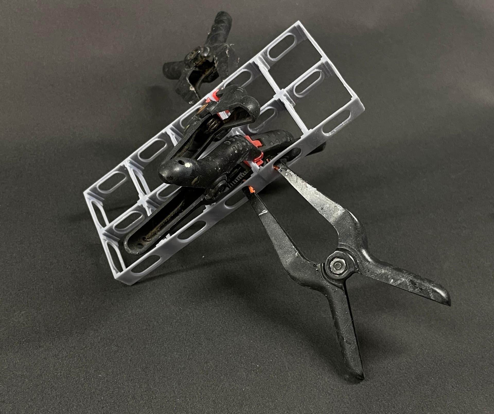
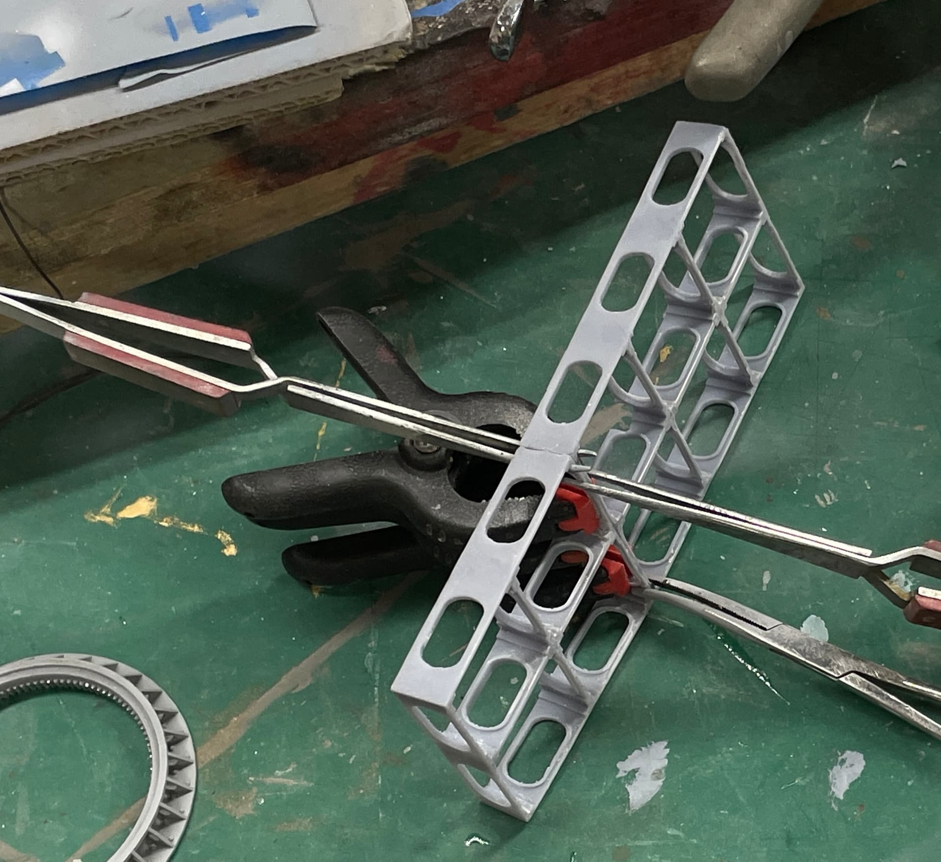
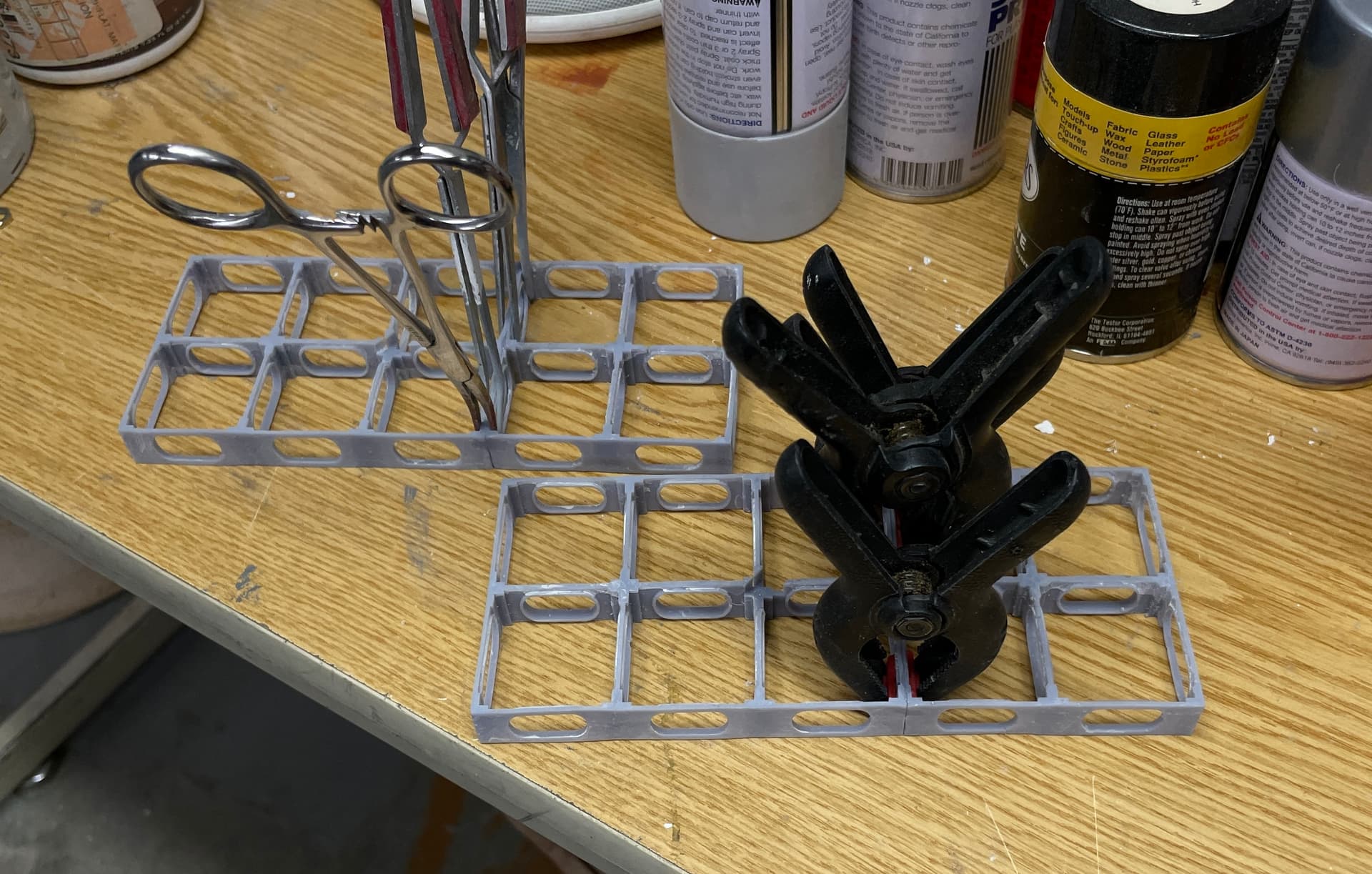
Built the first splinter deck assembly and number two is in the clamps. Number 3 is in the printer. That means only two more to build and I have that crazy deck ready for final assembly and paint. I’ve been trying out Gorilla Structural Adhesive. It’s clean and has good tack keeping parts kind of where you put them. It doesn’t cure fast, but that’s not a detriment in this case. And it’s good for lots of different surfaces. I’m using it to assembly these splinter assemblies and attaching units to the floors and walls.
Here’s the first subassembly joining… not yet glued
I added more goodies into the Upper Handling room. The Gorilla glue really works well and having some working time is really important. CA is just too darn temperamental.
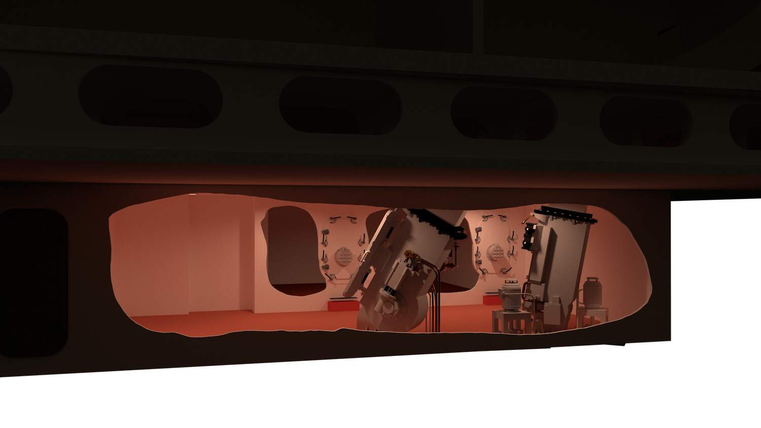
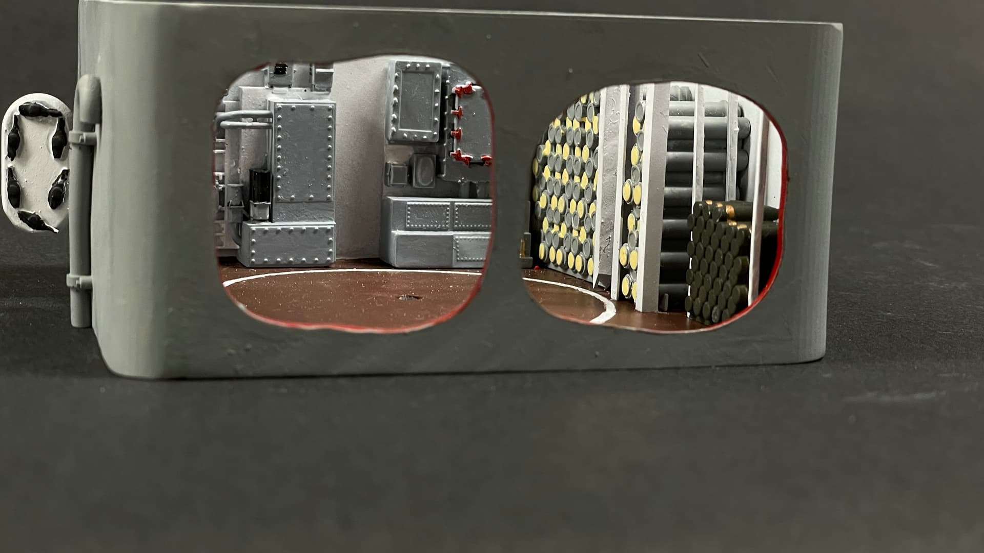
This is the viewer’s point of view. When liit it will be nice.
5 Likes
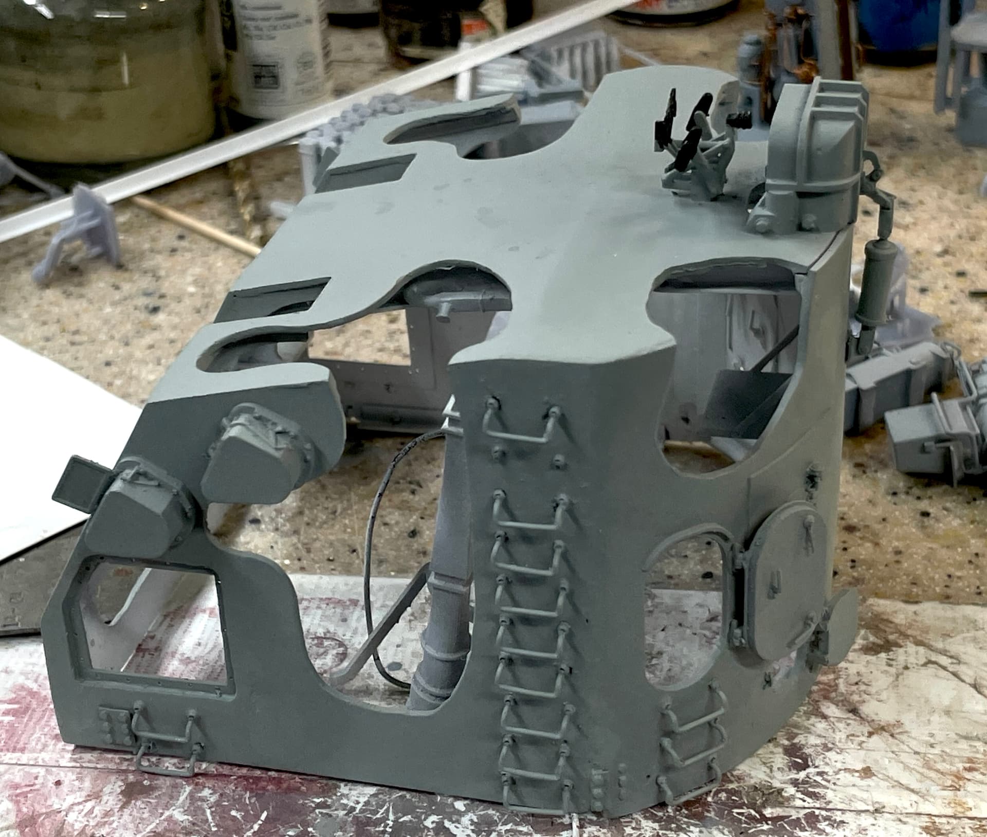
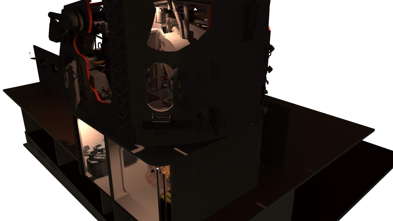
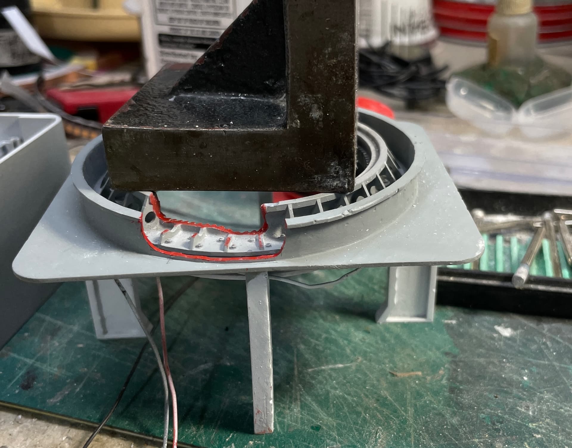
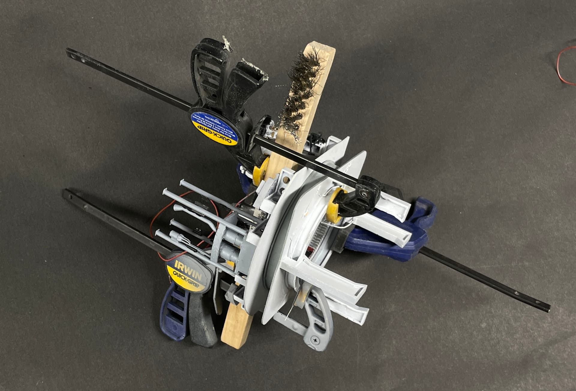
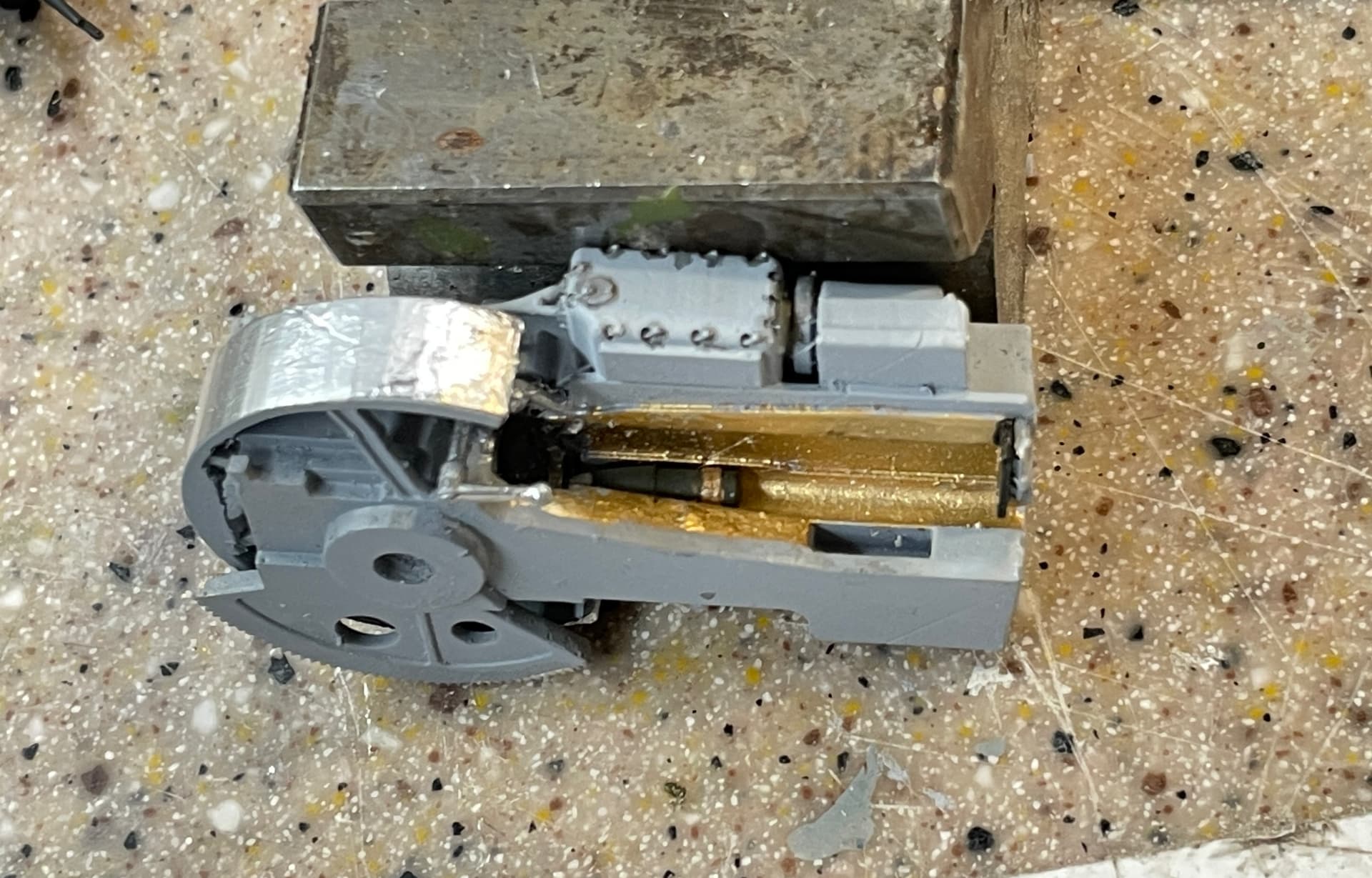
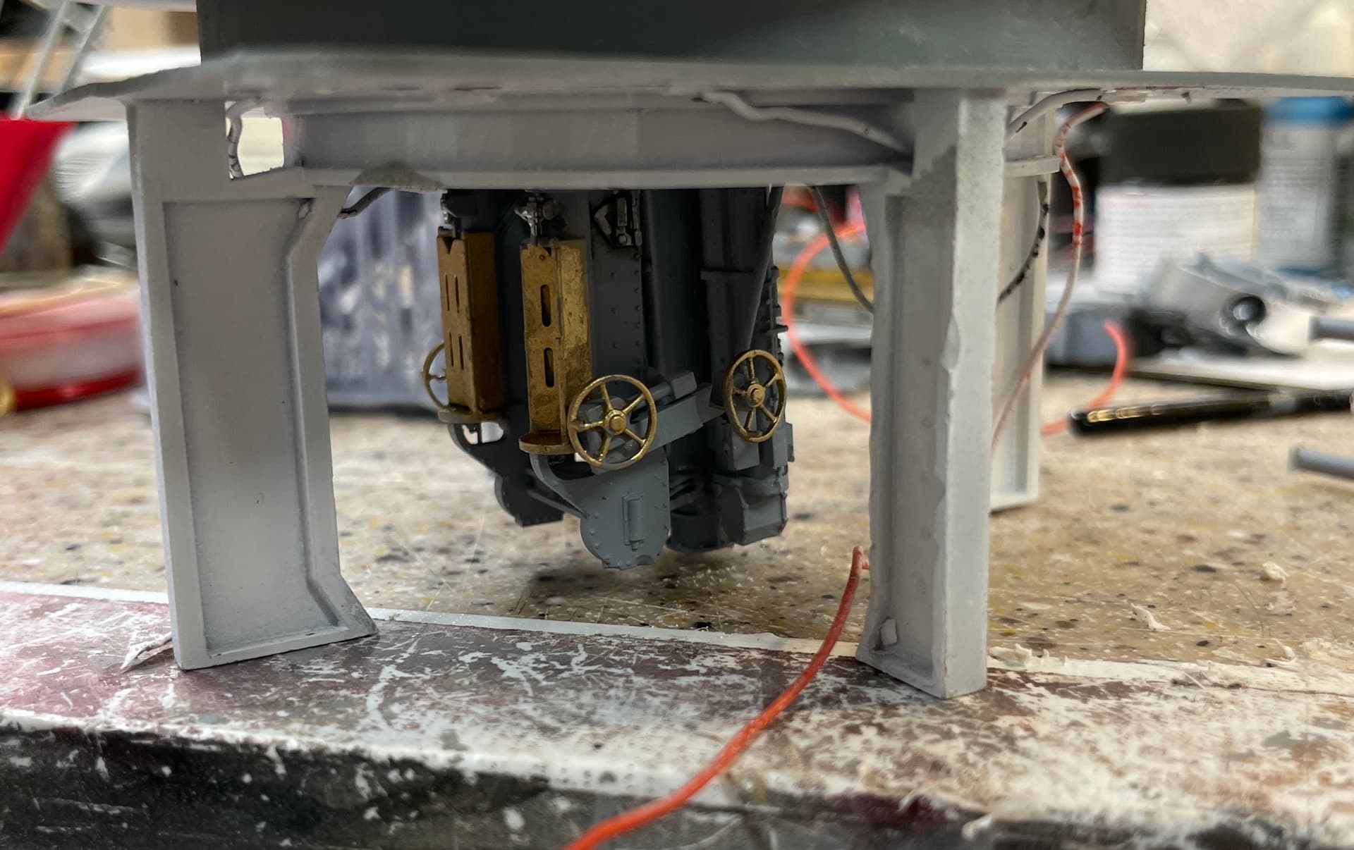
Assembly work continues. I made the cutaway for the base ring and barbette that should allow viewers to peer inside and see the ring gear and training pinion. I began adding units to the gun house, and got another Splinter module ready to go. The last of the five is currently printing.
The angle block is a gravity clamp needed to cure the Gorilla construction adhesive.
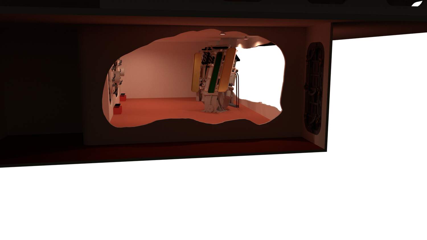
I’m photographing all the finished subassemblies for the AV program like this one.
This way, even if they don’t have a direct view they can see what’s inside.
The Splinter Deck modules continues to grow. One more to go and it will be done tomorrow. The modules aren’t yet glued together. It’s hard to visualize that this assemblage ran from the rear of turret #2’s barbette to the front of turret #3’s, about 375 feet (115 meters). Ryan says it’s a terrible space to crawl through. I’m just modeling a tiny sliver, but it gives the idea.
7 Likes
Work continues…
It was time to connect the ring frame to the gun house base. If I waited any longer, there would be too much very delicate stuff in the way to effectively clamp them together for gluing. I found that the training buffer (the shock absorbing device that stops the gun house from over-rotating into the ship’s structure) was forcing the mounting ring on the gun house to not seat into the ring mount. I had to do more surgery on the buffer to make it skinny enough to let the two mate properly. I even had to cut off part of the mounting ring at the rear so it would actually fit. It does now. All of this messing around is no visible.
The Gorilla structural cement takes 24 hours to fully cure, but you can unclamp in a half hour. It’s great for gluing dissimilar surfaces together, and dries with some flexibiity to it so it’s forgiving.
I assembled the last two Splinter Deck modules and they too will dry overnight and then I’ll assemble all five modules into the entire part.
I painted up some projectiles and glued them into their respective places in the gun house hoist and the load tray of the right hand gun.
I had to clip off the projectile’s noses so they would fit in these spaces. That’s okay because the fuse assemblies are inside the fuse setting sockets in the hoists and aren’t visible.
I did a bit more detail painting of more gun house parts in readiness for the clamps to come off tomorrow. I have another dentist appointment tomorrow afternoon. So I may or may not get more work done tomorrow. If not, it will wait until Monday.
I’ve got a request into Jim Sl he could give me some insight on the ceiling framing for those empty spaces on deck two. While I’m not going to furnish these compartments, I would like the ship’s structure more represented. They are holding up many thousands of pounds of gun house and UHR, and the framin below should reflect this. He’s been a bit unresponsive so I’m not optimistic that he can help me.
7 Likes
Besides taking care of some tax things today and watching the eclipse, very short session, but not to worry, did get some things done. The great thing about getting old, being retired and having a great hobby like this one, is that each day you’re in the shop, several things happen. Time flies and you’re fully engaged. The problem solving keeps the brain working well. And you have something remaining behind that wasn’t there before after each session. Compare this to doing crossword puzzles, smartphone games, etc. where nothing really ever changes and when you are ultimately gone from the is earth nothing remains behind to tell people what you did. Don’t get me wrong, I play a lot of games on my phone, but it doesn’t replace this.
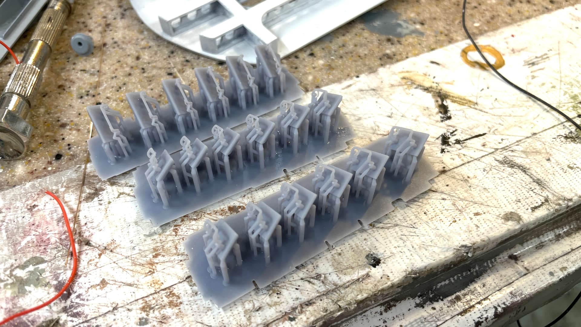
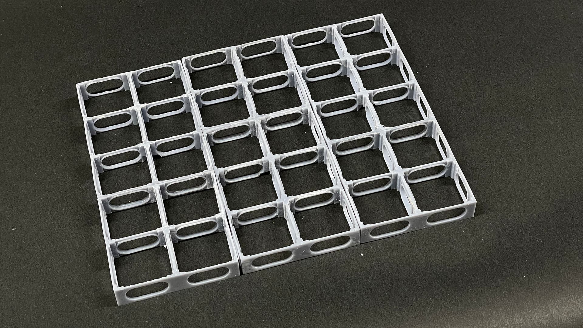
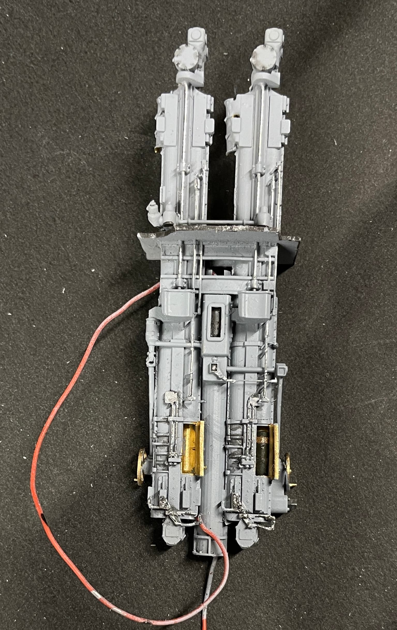
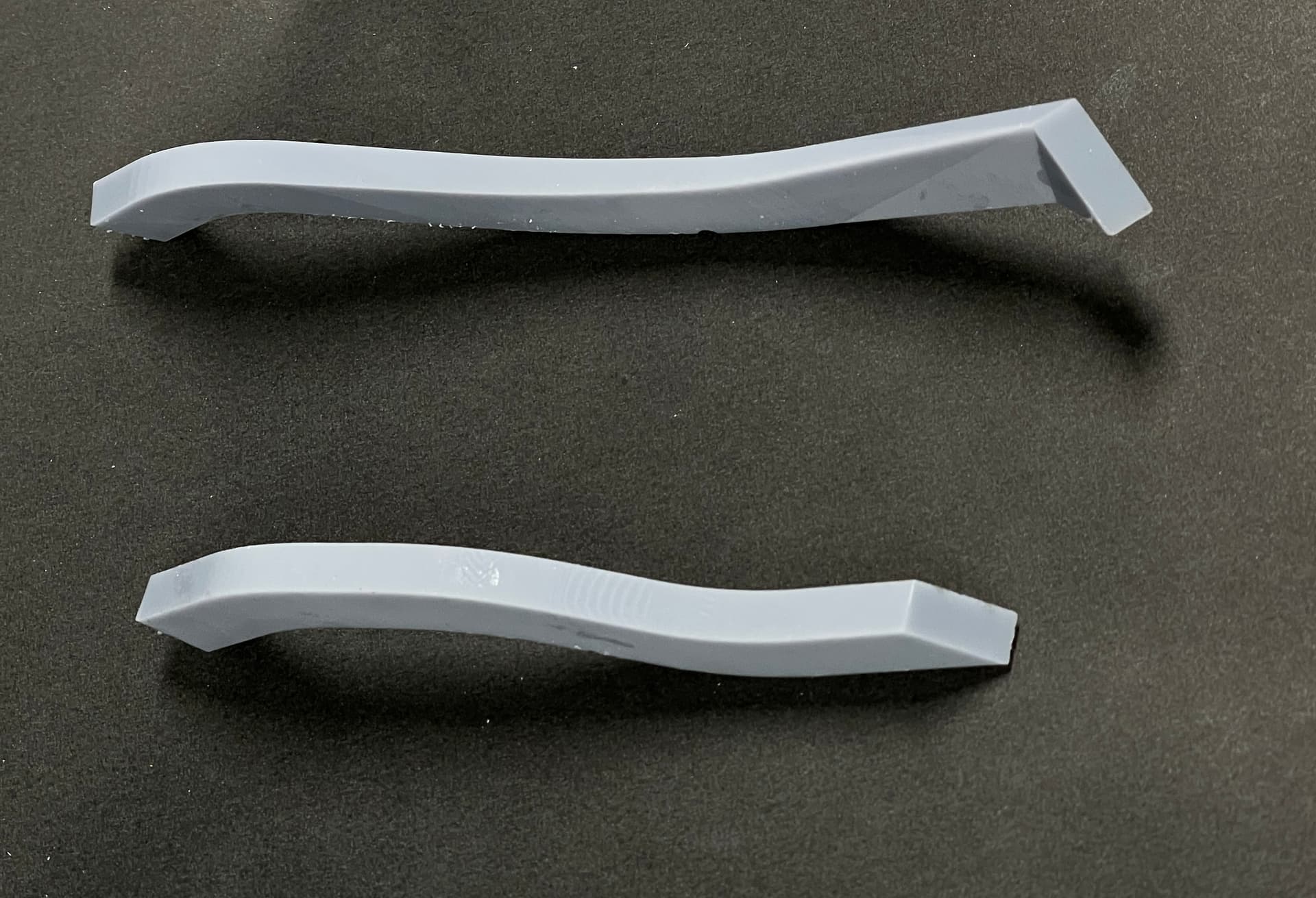
I got the trunks printed successfully. I printed two of each as usual. The picture shows them cleaned and post-cured, but not yet final finished.
I glued up all five Splinter Deck modules. I did it on a smooth surface covered by a piece of polyethylene so it doesn’t stick to the table. Put a square on one edge to keep them in line and used every clamp I had that would fit.
Design work on the magazine continues apace. I’ve simplified it a bit, but there’s enough ammo in it to give the correct feel. I’ve asked Ryan from more information about what’s going on at the ceiling. There’s a lot of cooling apparatus since this was the only air conditioned space on the ship during WW2, for obvious reasons. There’s also a door to the passage that I don’t have the correct sizing for. I don’t know if he can get into the ship now that it’s in dry dock. As it stands now, my wife and I will probably be able to visit the ship in dry dock in May. I’ll keep y’all posted on progress.
Lighting will be important to let people see into these spaces.
On another front… SketchUp 2024 upgrade was issued and all of a sudden almost every problem I was having with version 2023 was gone! Clearly, the problem was not with my MacBook Pro, but was with software that was not working well with the latest Mac OS upgrades. Instead of minutes passing when I was making a simple zoom command, it’s now instantaneous. It was re-drawing images as stick figures first before rendering them fully. That’s stopped. Booltools 2 was able to do a compllicated trim on the entire stack of projectiles, that caused me a half hour of work before. I couldn’t move large assemblies from one drawing to another becasue it sometimes took up to a 1/2 hour for the “beach ball of death” to stopped going round and round. It was getting so bad that working on this aspect of the project was frustrating drudgery, not fun and creative. I did have some problems porting over some of the many extensions that I had. Some needed to be deleted and reinstalled with fresh downloads. Others, like VRay, had its own upgrade and needed a fresh download. That took most of yesterday afternoon. All’s well that ends well and all is installed and working well.
8 Likes
Asssmbly continues…
The glueup of the splinter modules went well. I added some Bondic to the front seams just to present a nice face forward. it’s nice and flat and should assemble to the rest of the structure without much trouble.
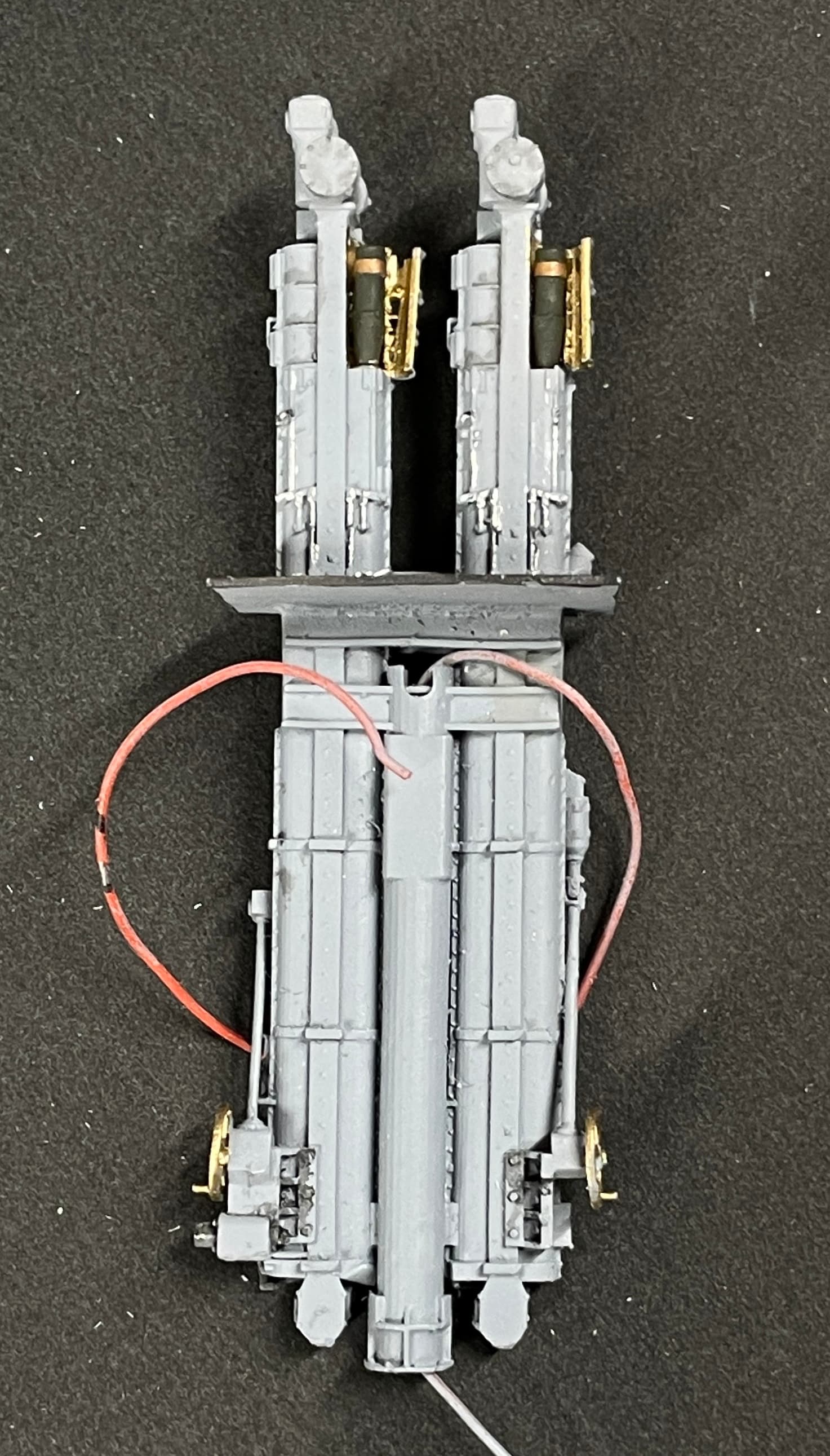
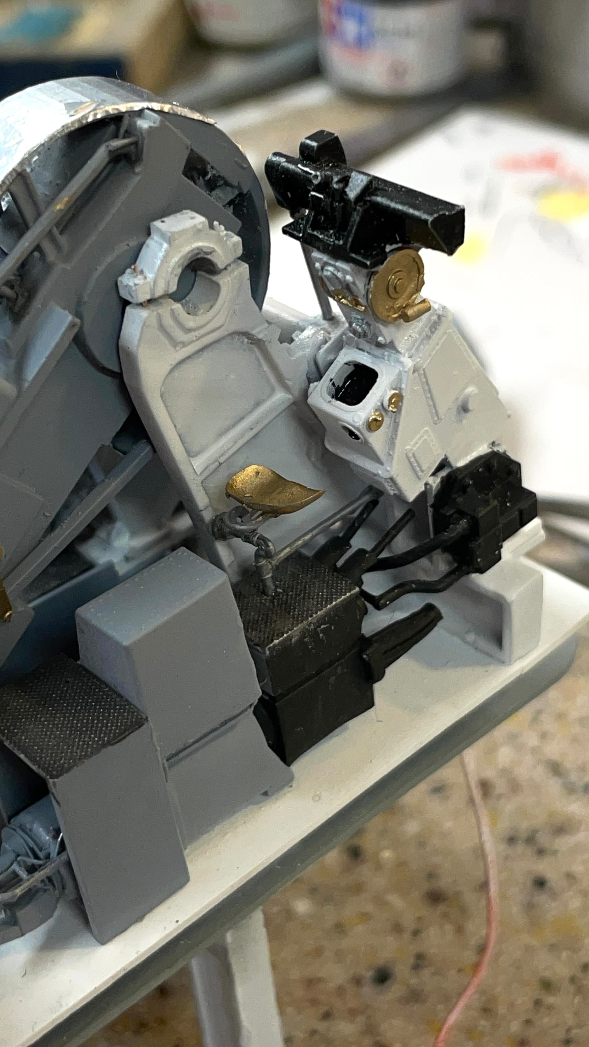
Getting the upper ammo hoists into the gun house was a different story. I thought I had the routine figured out, but that was not the case. First I had to rip off the officer’s platform that I had glued earlier as it prevented the powder hoist from moving far enough aft to let me manipulate the projectile hoist into place. Then there was engagement between the projectile hoist and the Sight Setter’s floor and seat assembly. I had to remove stock from the hoist’s floor so it would drop behind the front floor, not overlap on top. Then I had to removed more floor from the powder hoist floor so it too would fit flush with the projectile hoist floor. All of this required a number of insets and removals, each of which was poised to wreck these delicate parts. I only had very minor damage and for that I am thankful.
Once again, using the Gorilla Glue earned its keep since it gave me long working time to keep fussing with these parts. CA would have been a disaster. I used the gravity clamp to hold the powder hoist floor down flat. I tried conventional clamps, but they did’t ahe the reach I needed.
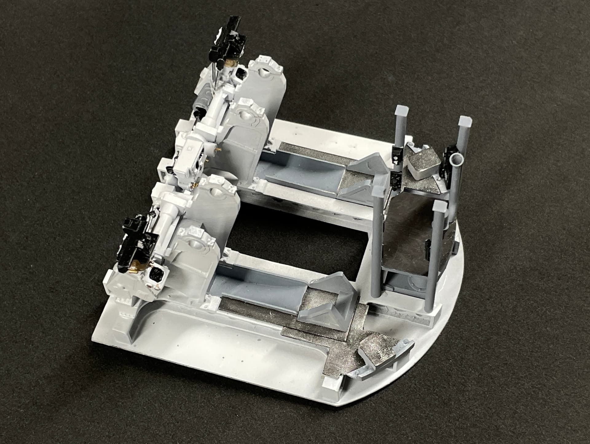
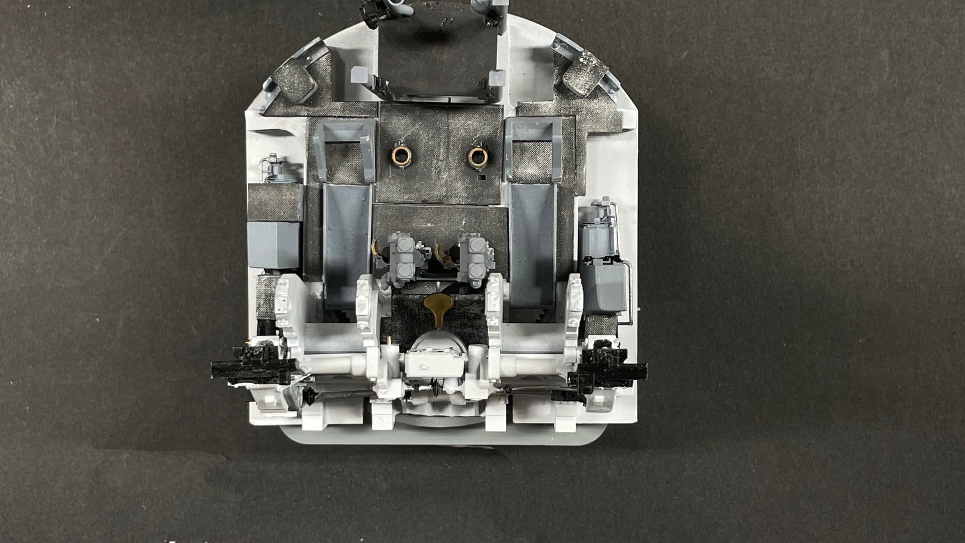
I also glued in the power systems for training and pointing and the sundry floor pieces they have. I think I’m going to use these images for the AV since you can see the pumps clearly. When more stuff goes on it will be more confusing.
Tomorrow, I’ll finish the Gun House installations including the pointer and trainer’s seats. The last thing to go in will be the gun slides and the sight checkers sights. The barrels go in AFTER the gun house shield is installed.
I started laying out the floor and wall pieces, even though I still have questions about the ceiling layouts of the spaces. I have to do all the layouts from coordinate measurements. For some reason, Corel Draw is NOT finding my HP printer. Doesn’t matter whether I used WiFi or USB line. This is important. Coreldraw lets you print out images larger than you paper size by tiling the images so they can be taped together. I wanted to print them full-size so I could use them as patterns and simply cut through them. Instead, I’m working with traditional layout tools and it’s much more tedious and error prone.
8 Likes
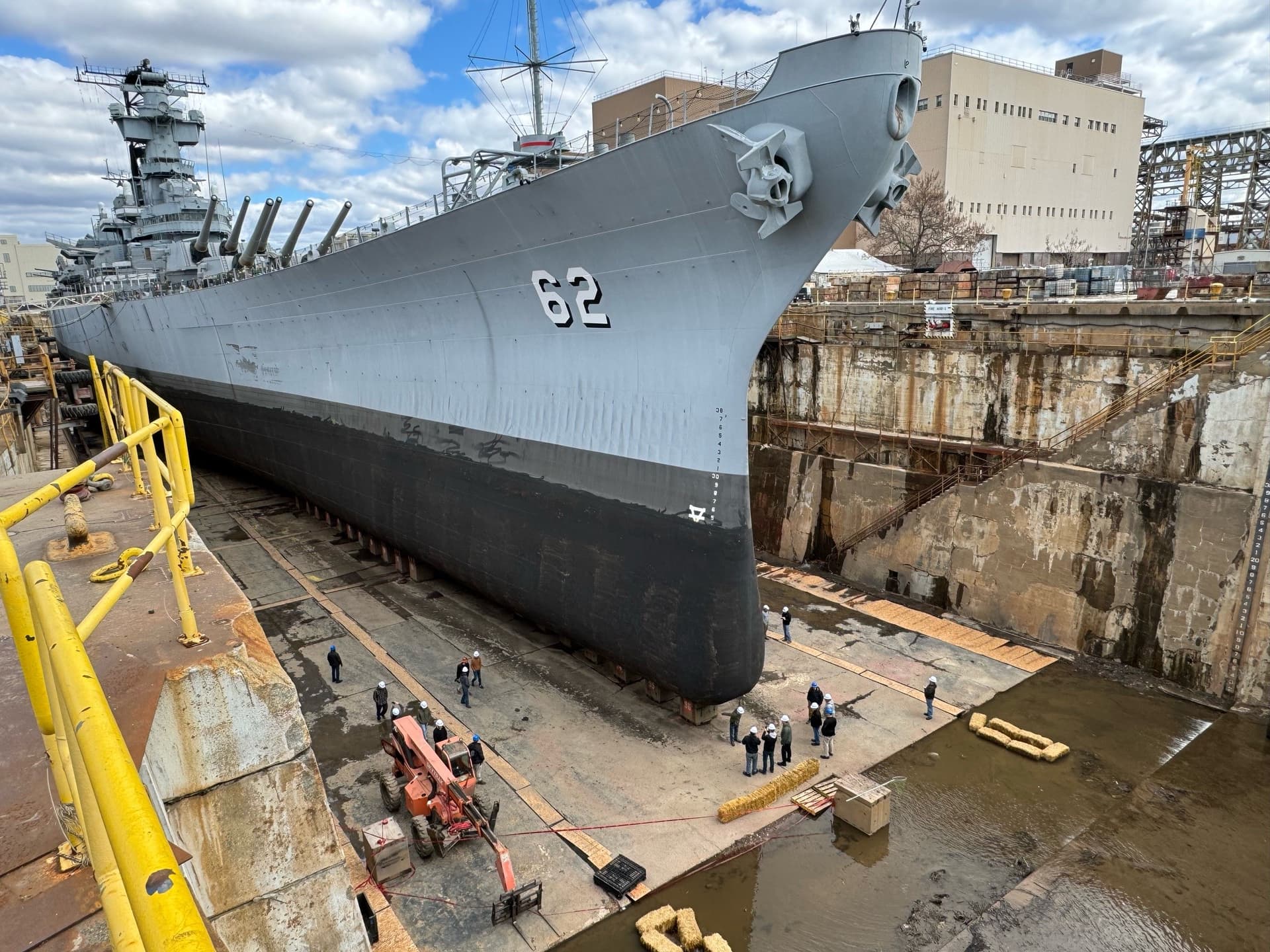
Before I delve into today’s stuff, take a look at this. It’s my favorite battleship in dry dock in Philly. We’re planning on seeing it up close and personal in May. At least that’s the plan. Gives you some sense of scale to see just how big ships really are and how big really big ships are.
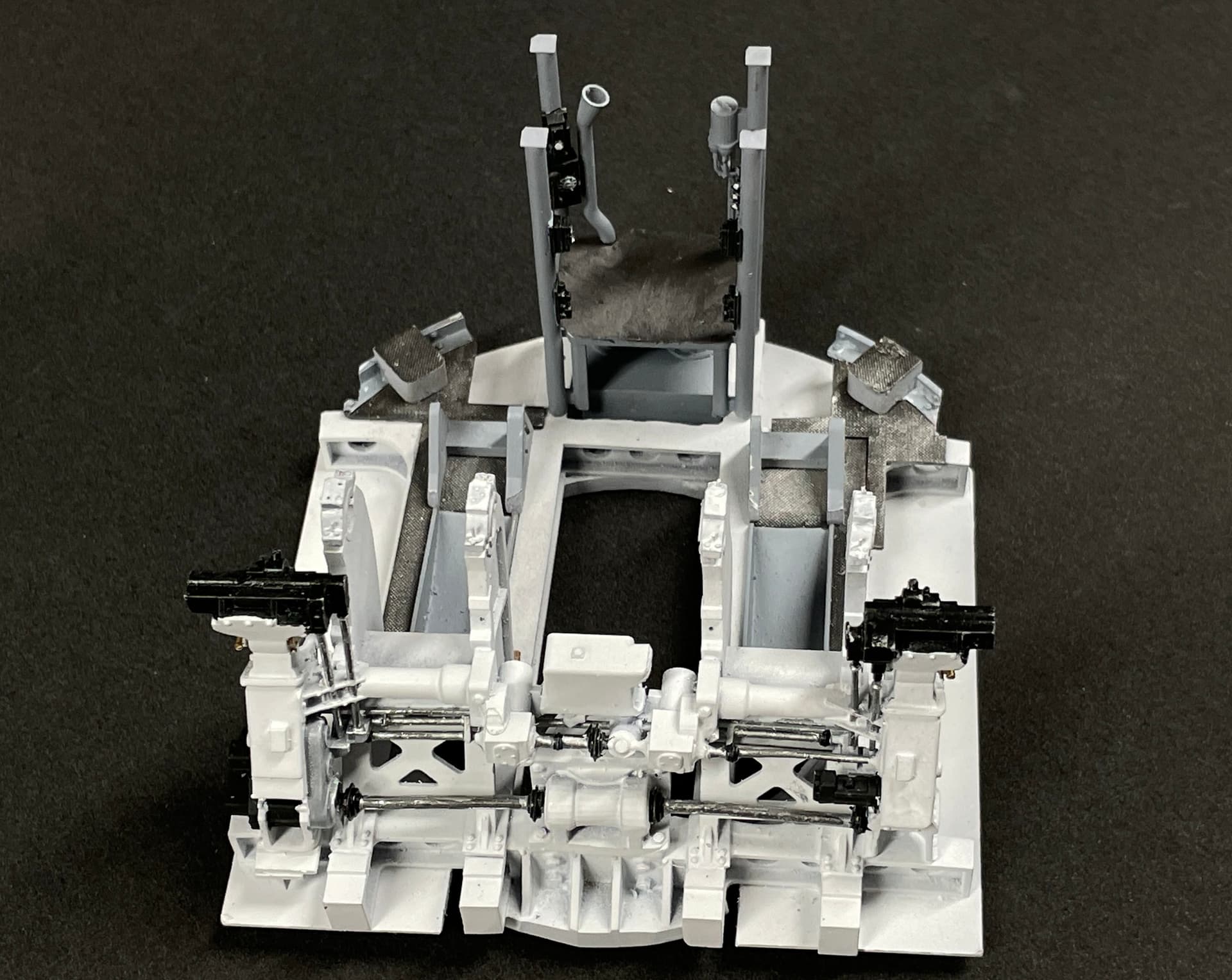
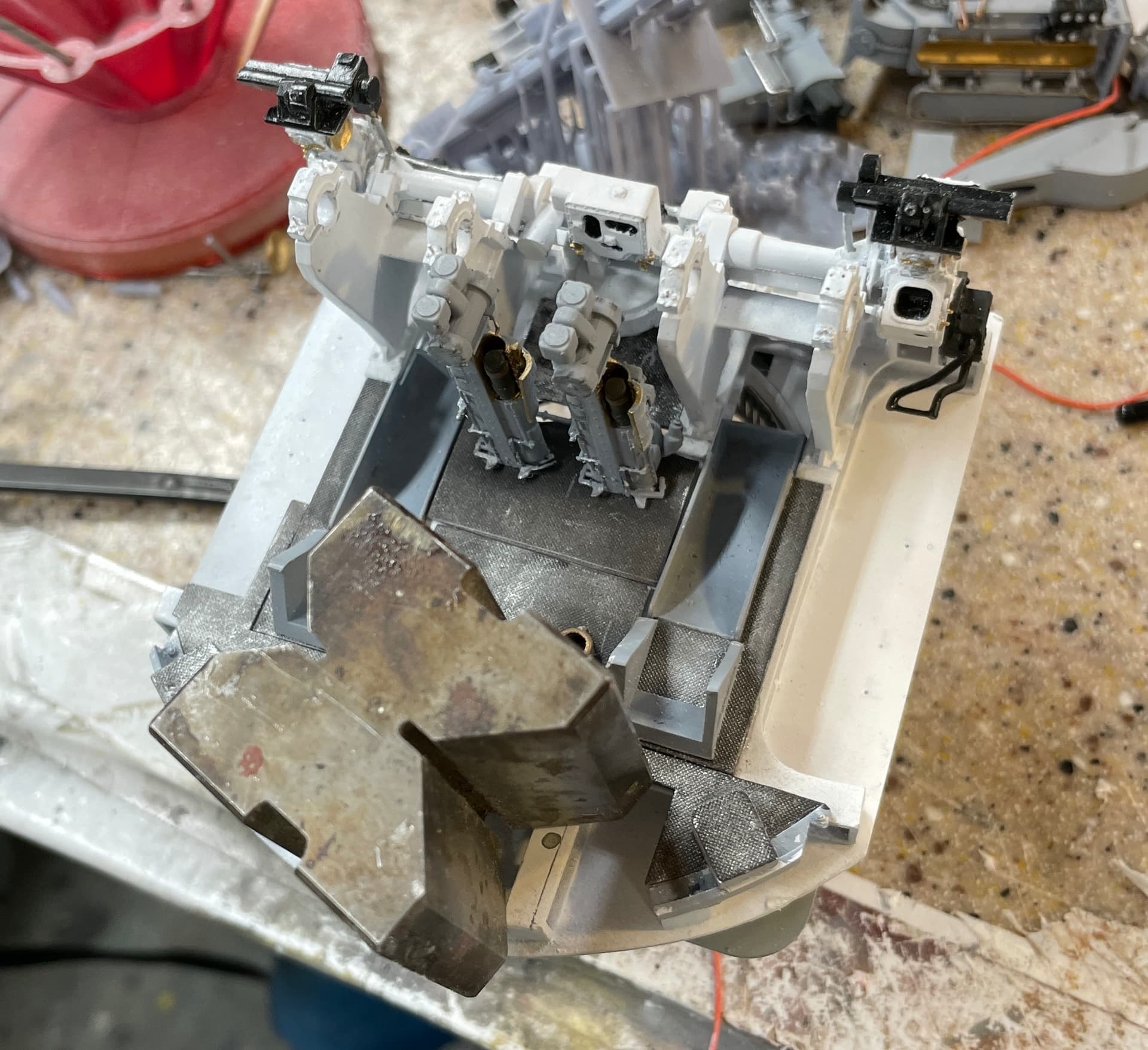
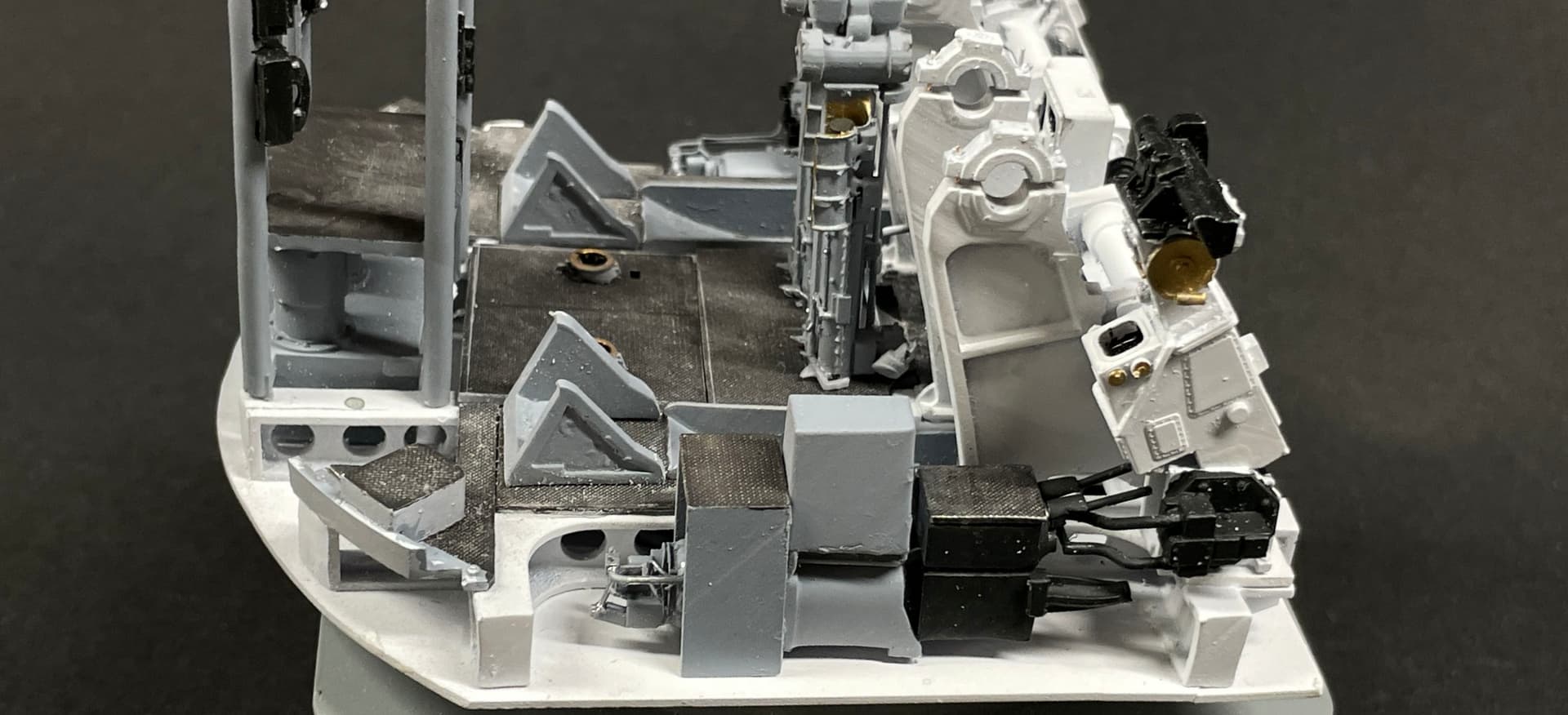
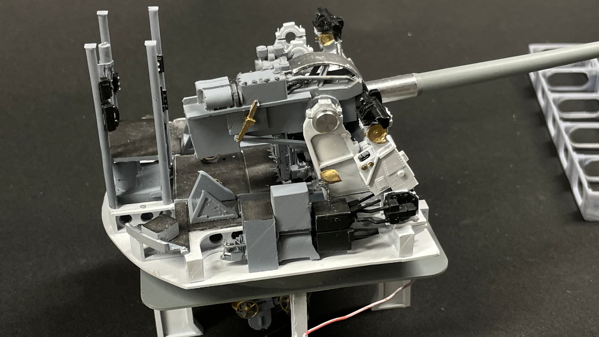
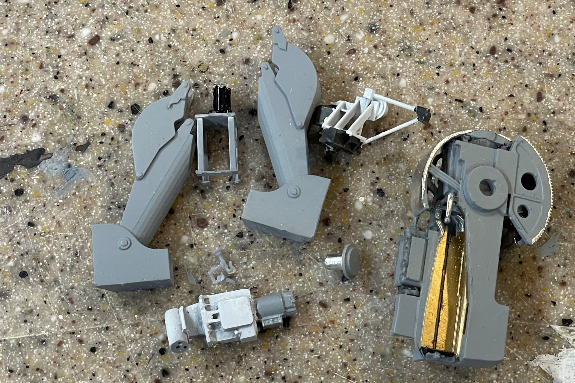
Sometimes the smallest details take the most work and aggravation. The pointer’s seat was one of those things. It broke so many times trying to fit it that I replace the support with some phos-bronze wire. I replaced the seat itself twice using spares, but the support gave out at last until I replaced it.
Didn’t have as much trouble with the trainer’s position. I got its seat in place without damage.
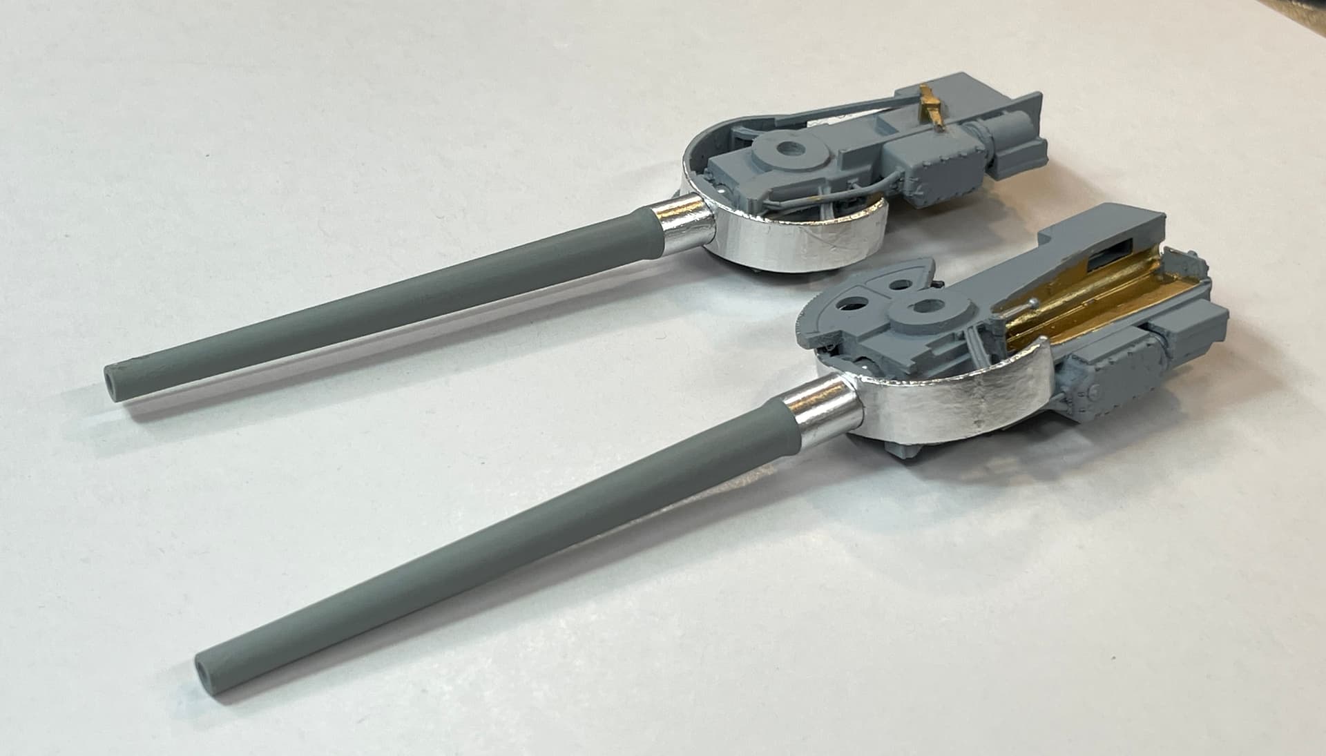
I then installed the right hand gun. The trunnion caps were being very finicky. Should have used a larger gauge wire when I did that part. If they don’t hold I’ll redo them with the larger size.
So here’s all that’s left in outfitting the gun house.
I continued cutting some of the floor pieces, but ran into concern that my alignment holes were not correct. I printed the 5" cartridges to further decorate the hoists and gun loading tray.
9 Likes
Are you planning on doing the dry dock hard hat tour ?
Great work. Really impressive how you problem solve to overcome the hurdles you’ve faced
The whole deal is one giant problem-solving experience from start to finish. It’s what really makes it fun. It’s also what kept me from doing custom modeling until I was well into my 60s. Didn’t think I had the ability to do that.
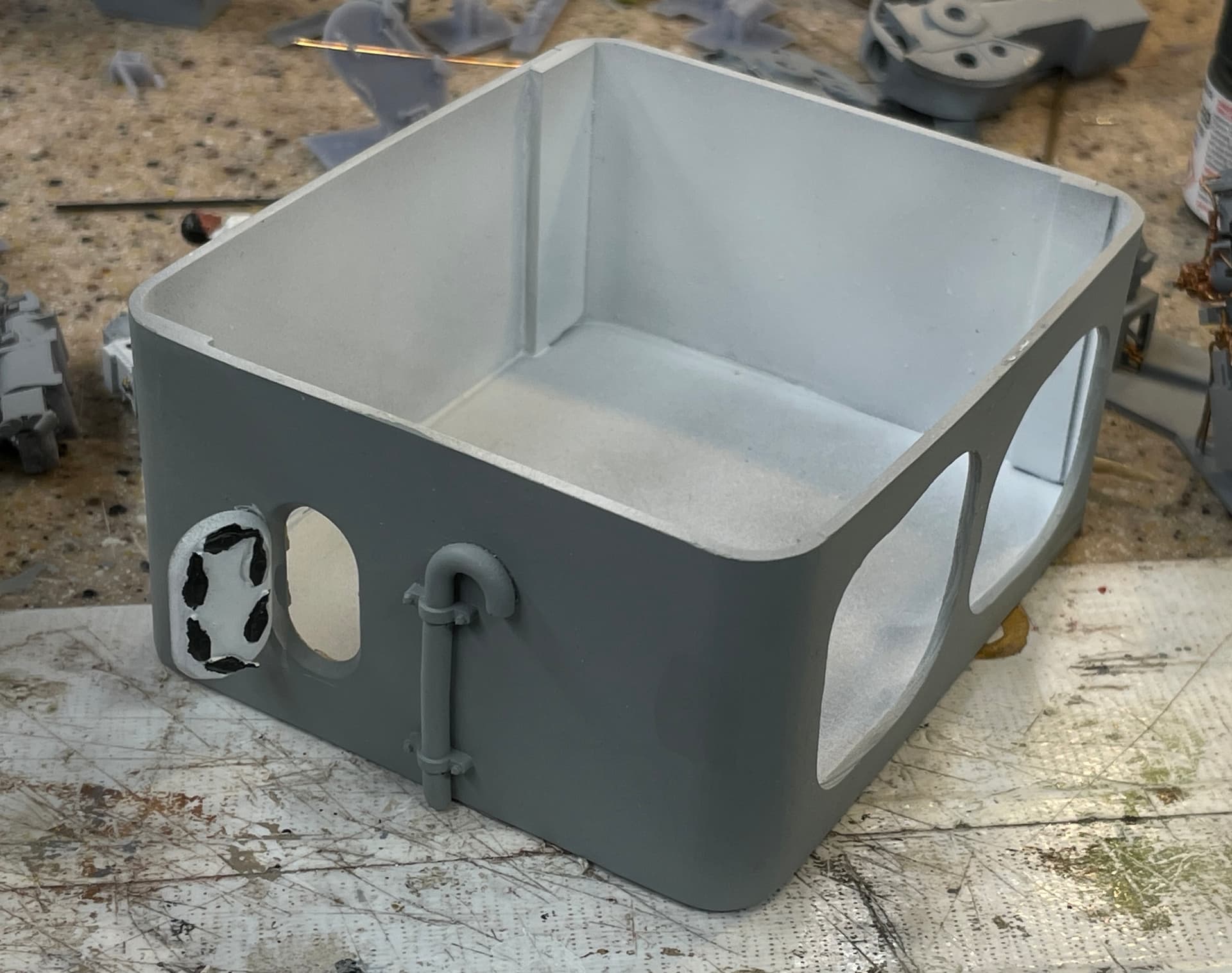
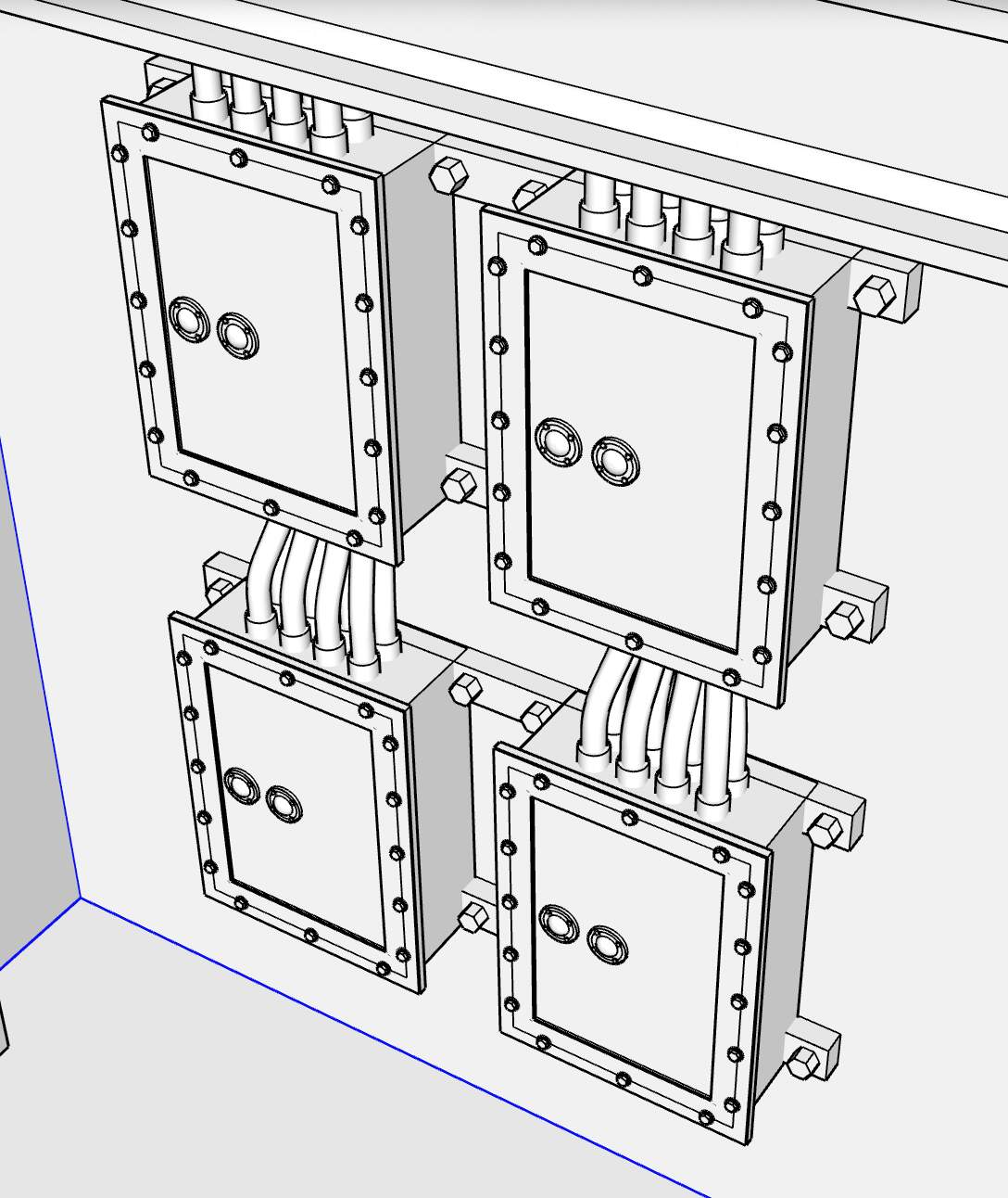
There’s only one 3D print left to do after today’s work. All the rest are drawn and in the printer or waiting in the queue. These panels were the last parts of the magazine I needed to design and print. I still have to deign and print something resembling a porthole for the little bit of exterior superstructure that I’m including in the model.
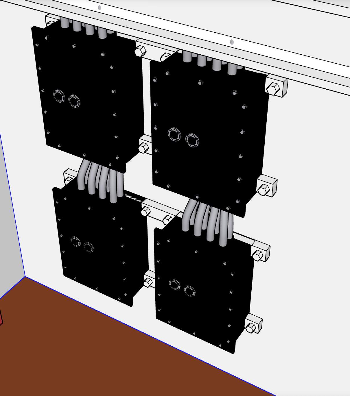
Here are the panels in the lower handling room of the magazine.
Here’s the SU drawing:
I simplified the cabling and made the wall mounts more robust for the sake of printing and asssembly.
And here it is in color.
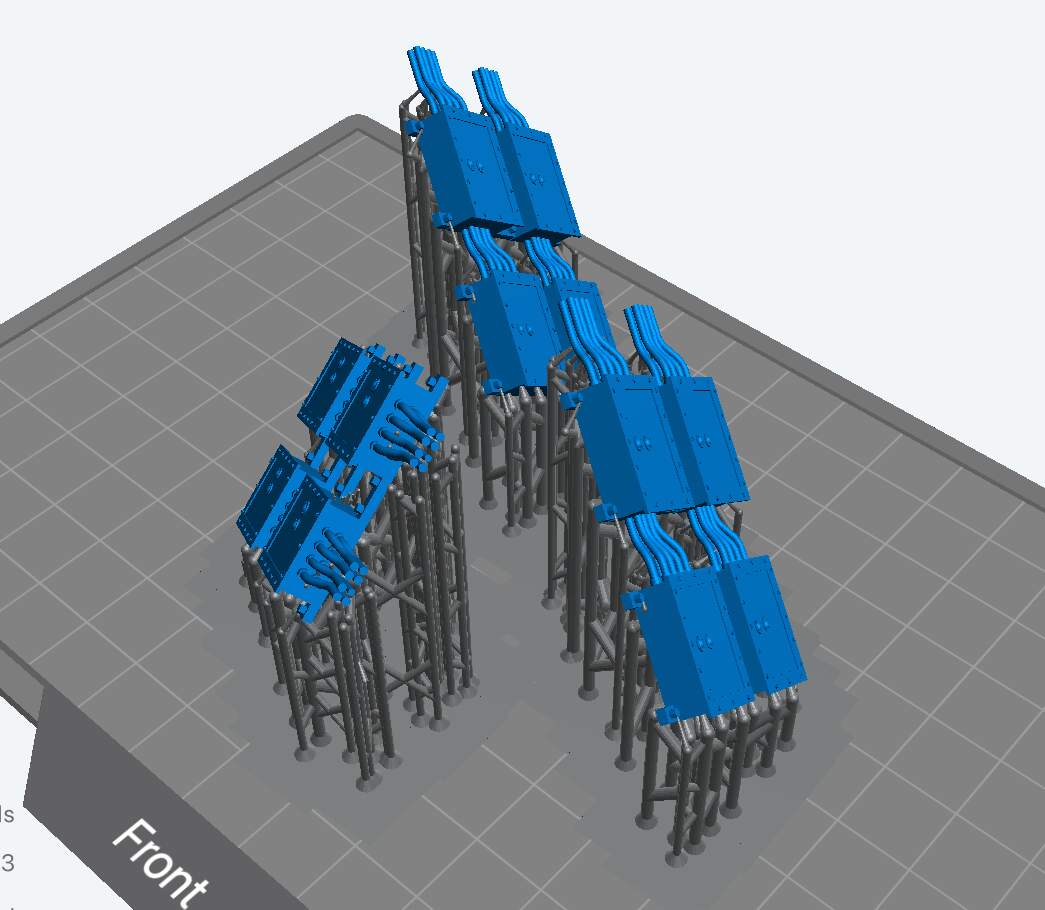
And lastly, here they are on the slicer. I only need one set, but I ALWAYS print more. The printer doesn’t care.
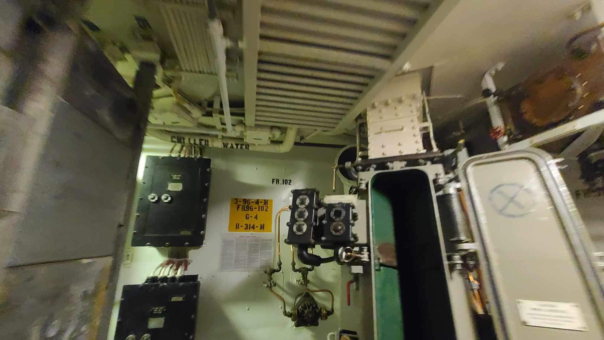
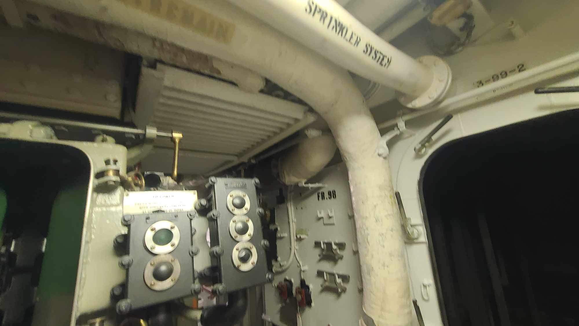
Still don’t know what I’m going to do about that ceiling. It may mean more printing. The question is how can you view it? Unless you’re a little kid looking up or an adult on your knees, it will be very hard to visuallize. Here’s another shot of the ceiling showing the cooling coils that are all over the place.
The trouble with designing this aspect (besides final visability) is not knowing what it REALLY looks like. It’s the blind men describing an elephant. I can’t understand how it all relates to each other. I would love to have a piping diagram. Even though I’m visiting the ship in dry dock in May, folks aren’t allowed into the ship due to no saftety systems functioning. So I can’t do my own survey. I can’t even figure out what’s happening with the ship’s framing. Your opinions on this aspect would be appreciated.
6 Likes