BLOG: Kitty Hawk 1/35 SH-60B Seahawk

The checked out the RedOak site and found four that would be great. That said, the $100 isn’t so great so I’m going to hold off until the model is further down the road and see if it will justify the additional investment.

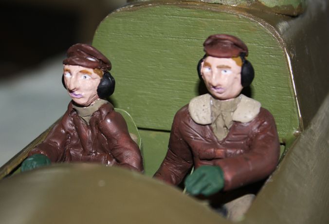
I am very envious of the people who create such beautiful figures. I have little or no talent for it. I had to sculpt my own bomber crew for a 1:16 B-17 RC model I built 10 years ago for a commisision. My figures came out like Nick Park’s “Wallace and Gromitt”, as evidenced by this picture. The co-pilot looks like he’s facing iminent death.

And that was after reading about how to do it. I’ve learned some more since doing this. I was using Sculpey and was trying to form the entire figure before curing in the Toaster Oven. I’ve since learned that you can work it in layers, getting the basic shapes down, firing it, adding more details, firing and so on. This way you don’t keep disturbing the things you’re getting right by working on the outer layers. That said, I’m still no sculptor. So if I want a crew, I’am going to have to buy it or find STL files somewhere and print my own.

The model did fly as can be seen in this video. I hadn’t built and RC plane in 25 years before doing this one.

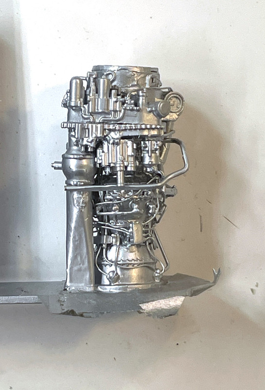
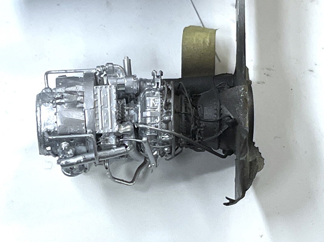
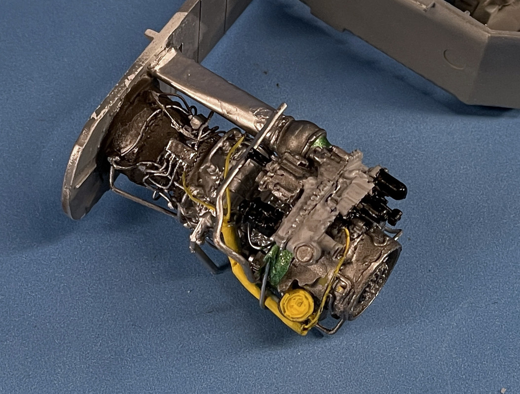
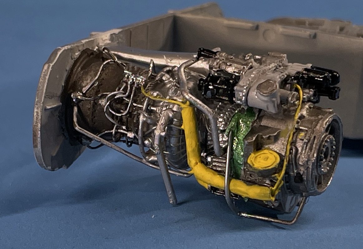
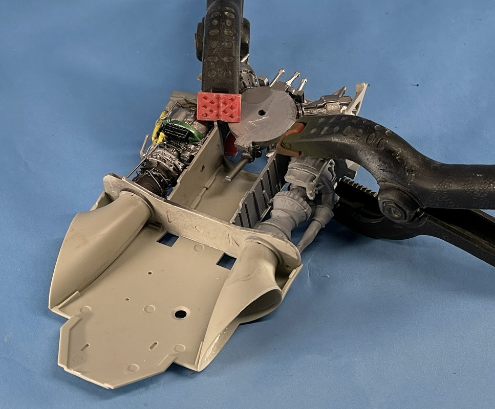
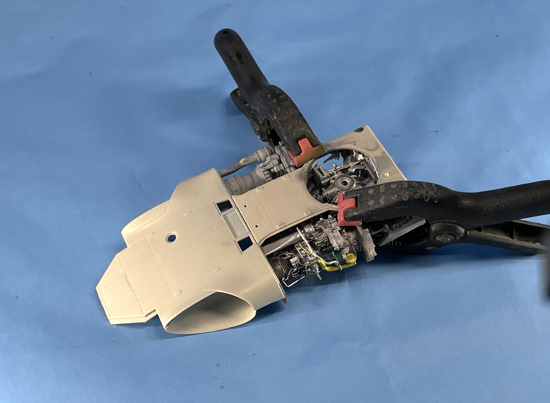
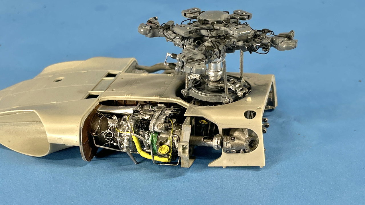
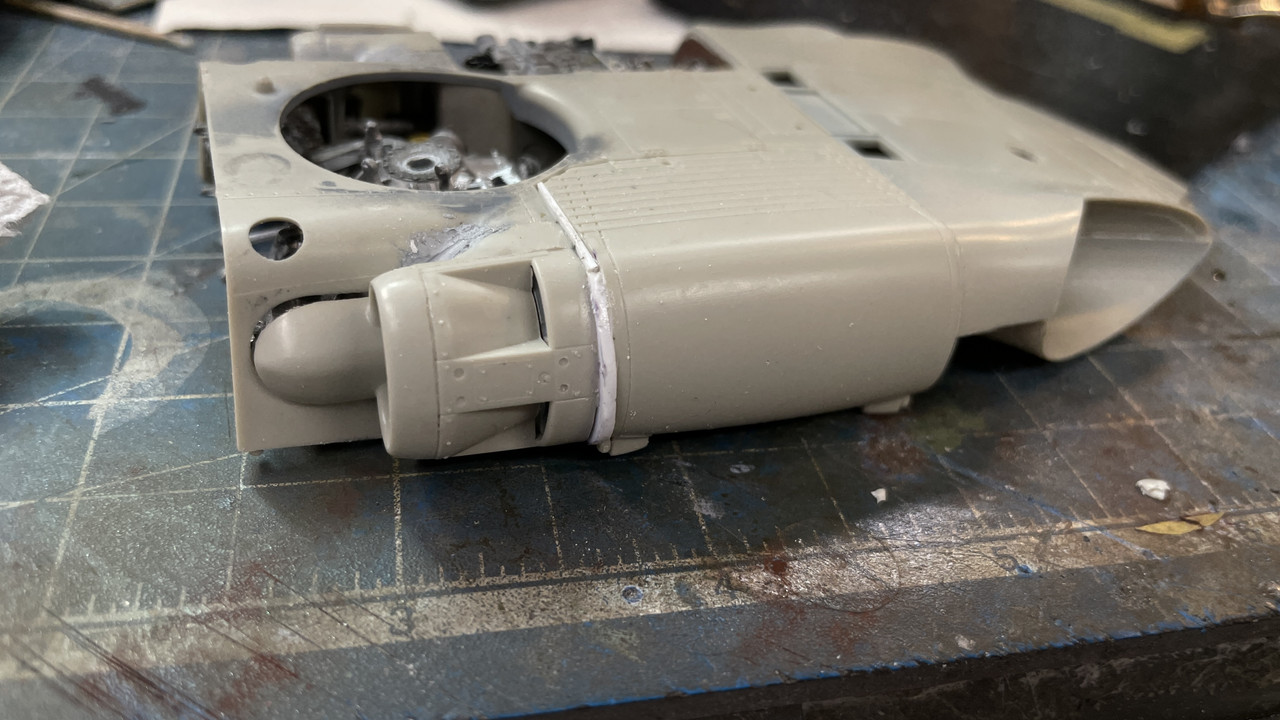
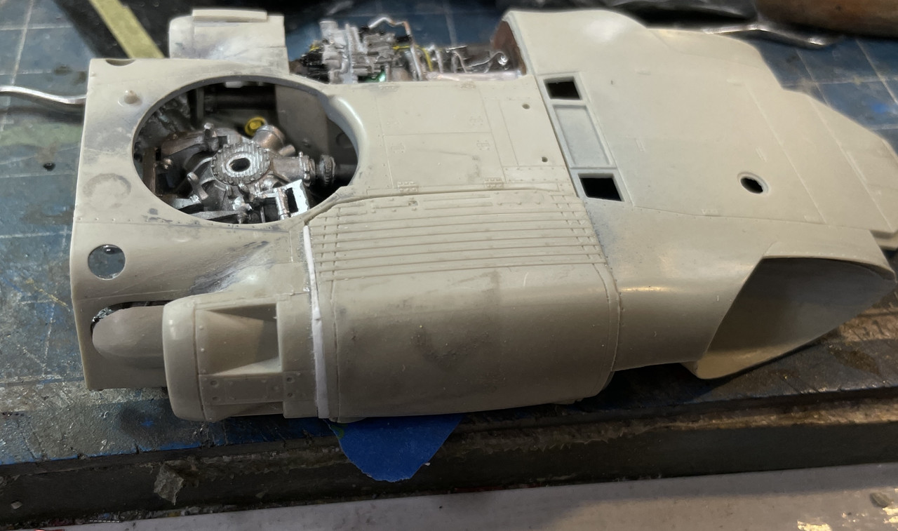
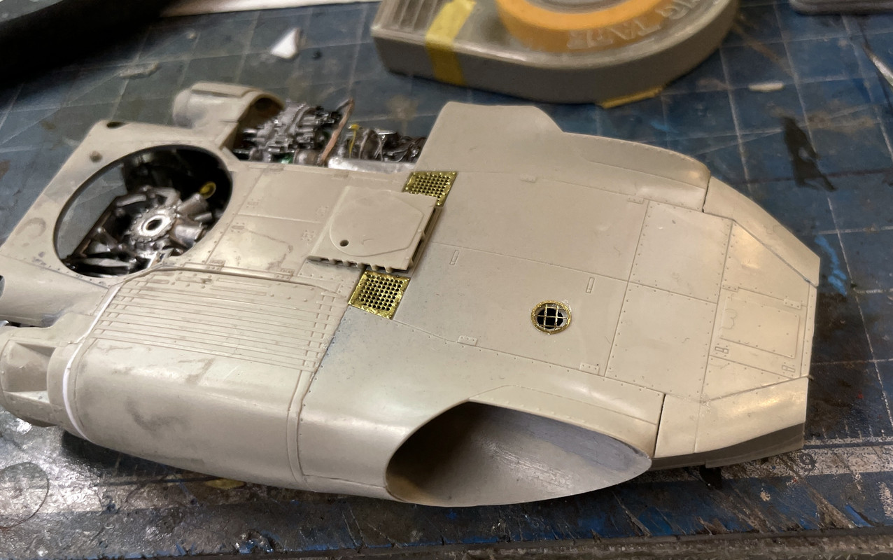
I primed the bulkheads with Mission Paints Dark Ghost Gray which is called out for the exterior color for the verison I’m doing. I then set this out to dry and continued working on the main rotor hub.

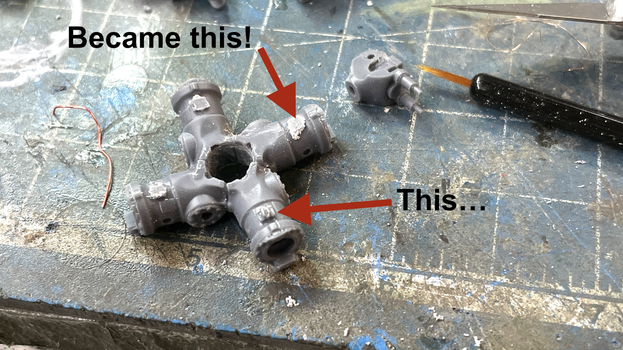
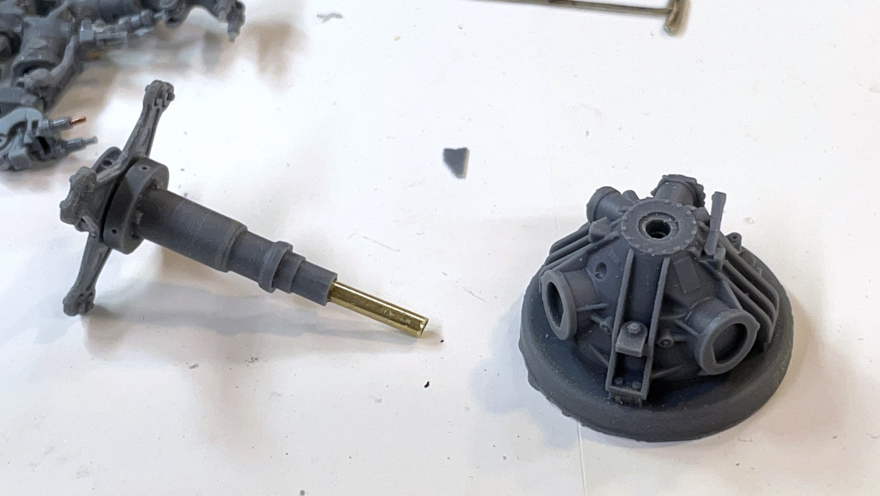
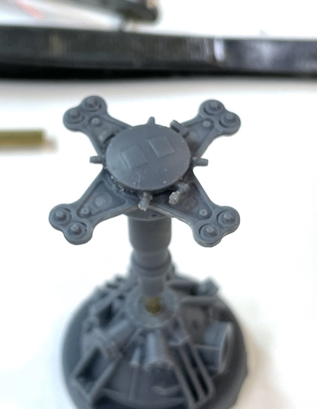
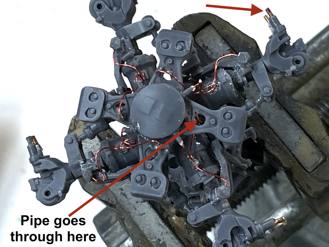
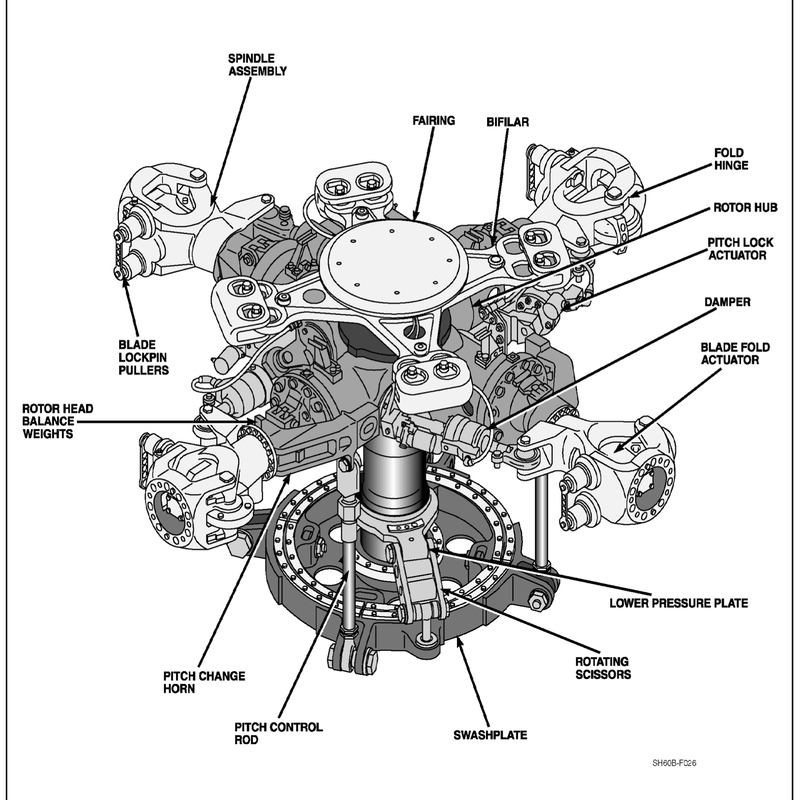
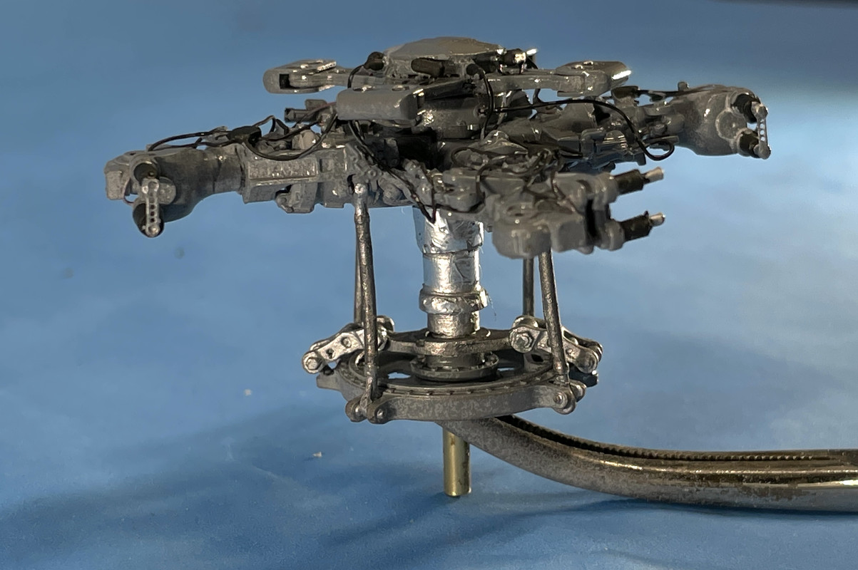
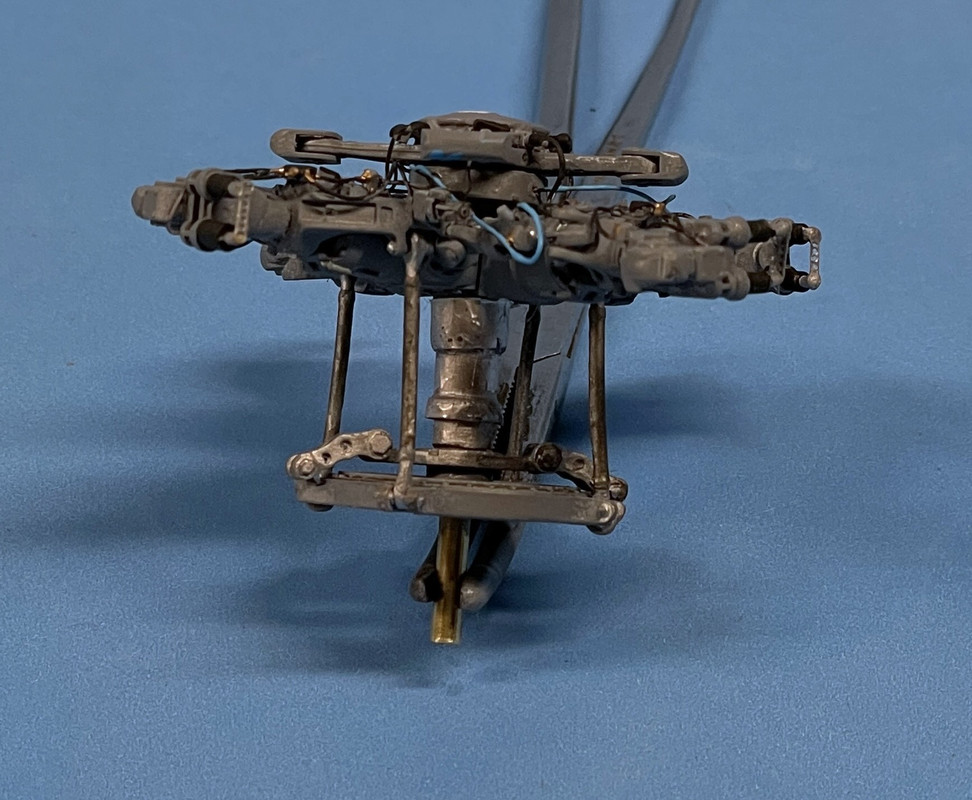
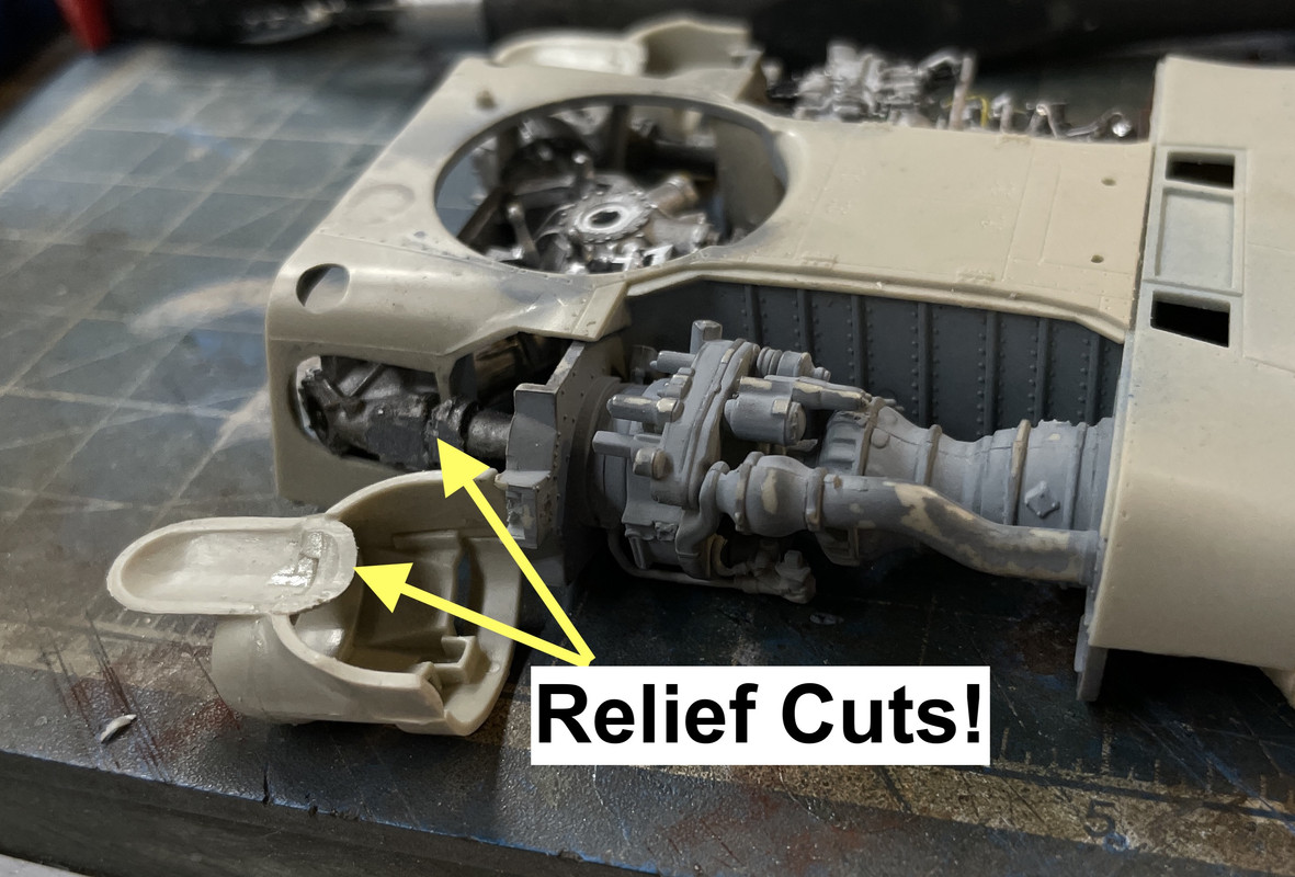
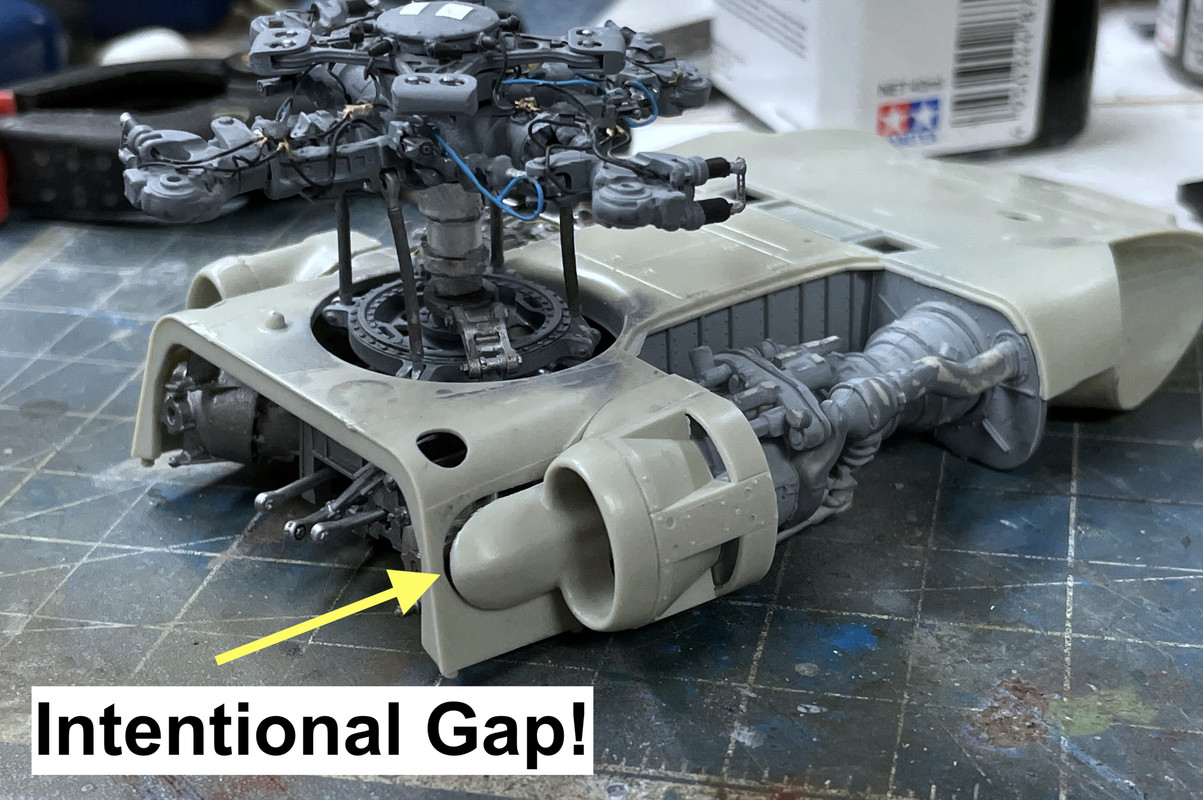
The next bit required a three-part assembly with lots of cleanup. This time I was able to use my razor saw or #11 blade to remove the sprue. You have to remove a web that’s in the middle of a curved surface. This shell mates to the other part. You had to be very careful in removing the exess around the shaft portion of the mating part. There were extended flats that are required to correctly position the seond part’s angular location. It would be bad to accidentally cut them off when doing the clean up since the geometry is very complex and it would make building the hub much more difficult.

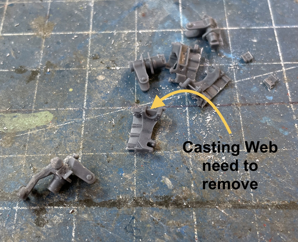
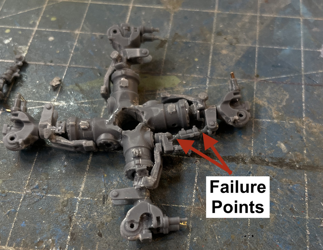
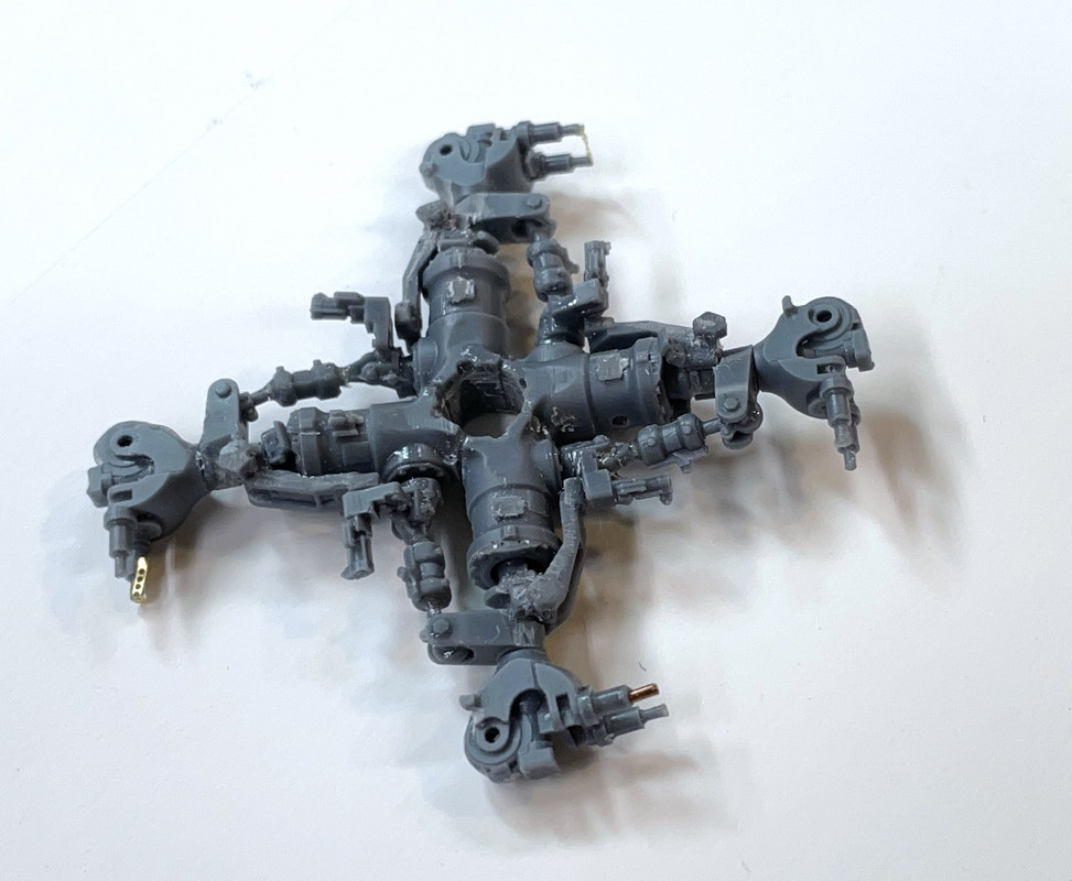
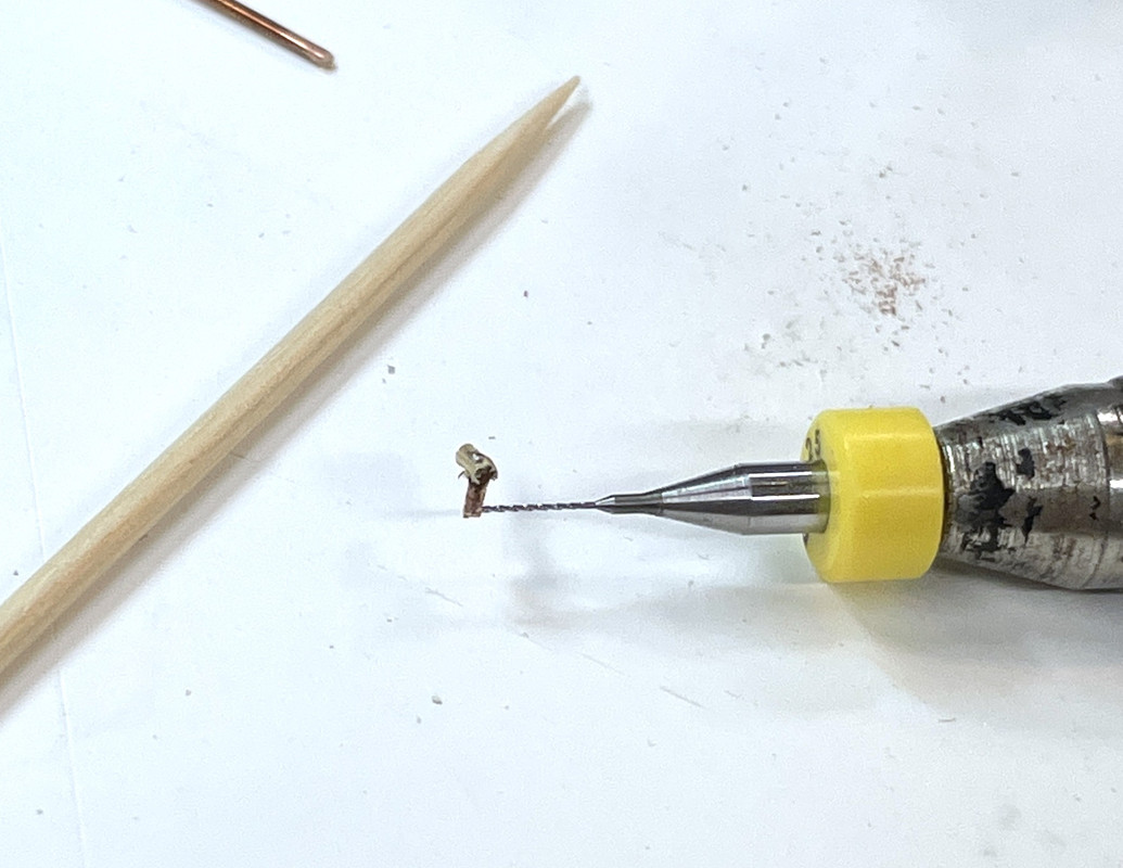
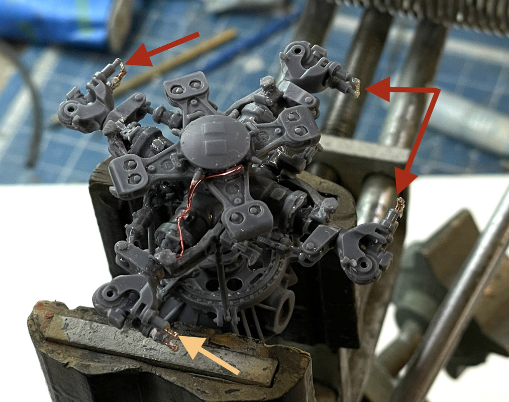
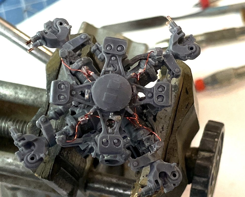
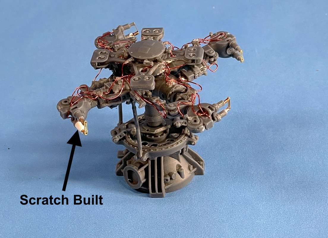
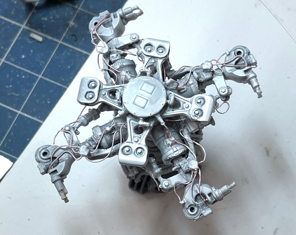
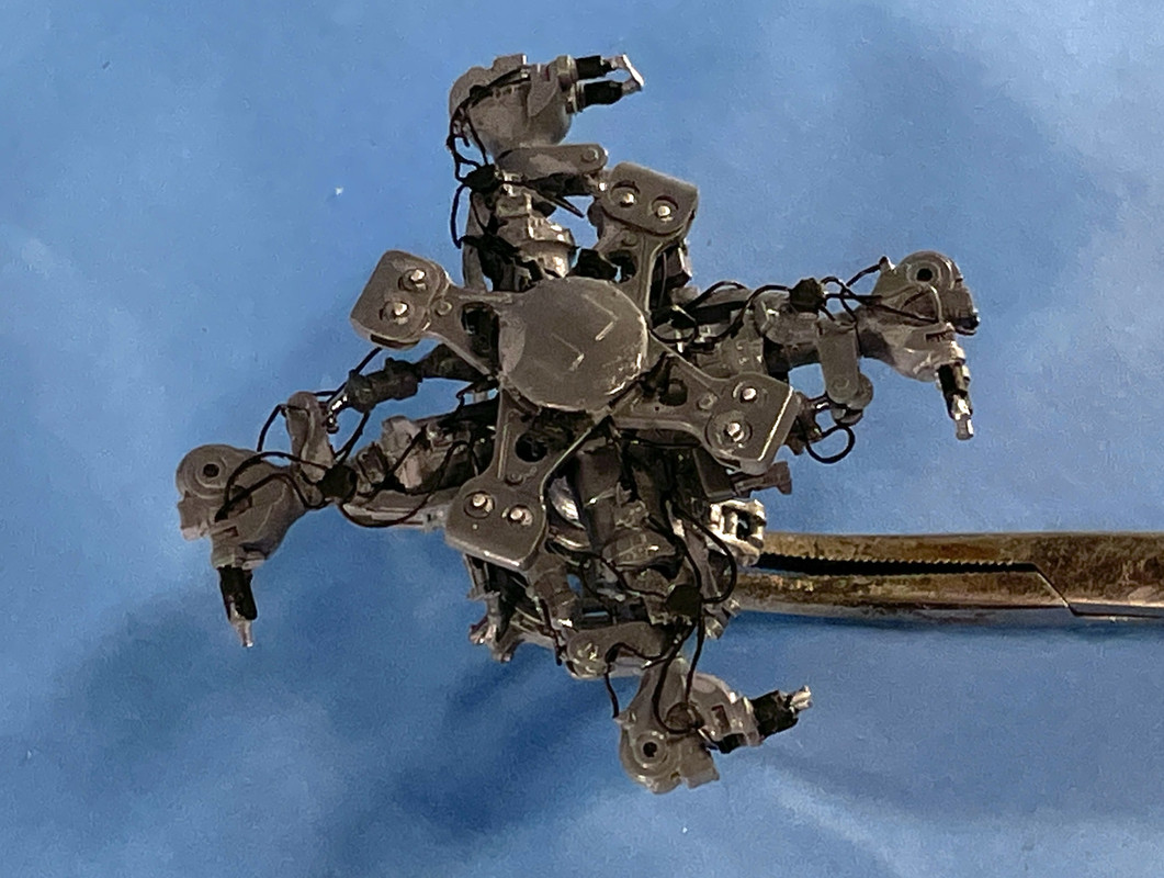
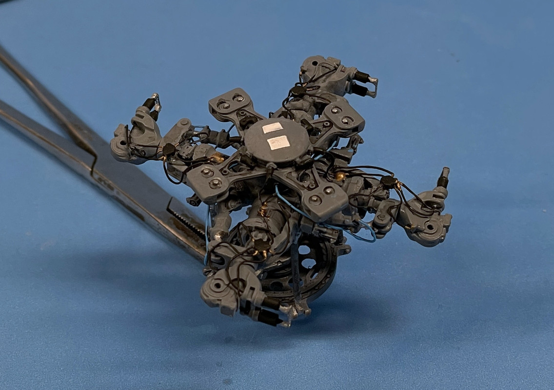
It took almost an hour and a half to assemble the four rotor attachment parts. There’s one more piece that goes into this that is the actual rotor blade hinge point. This part is not used on the Army Blackhawk version without the folding blade requirement. To properly remove the flash you DO need to be a bit of a sculptor.

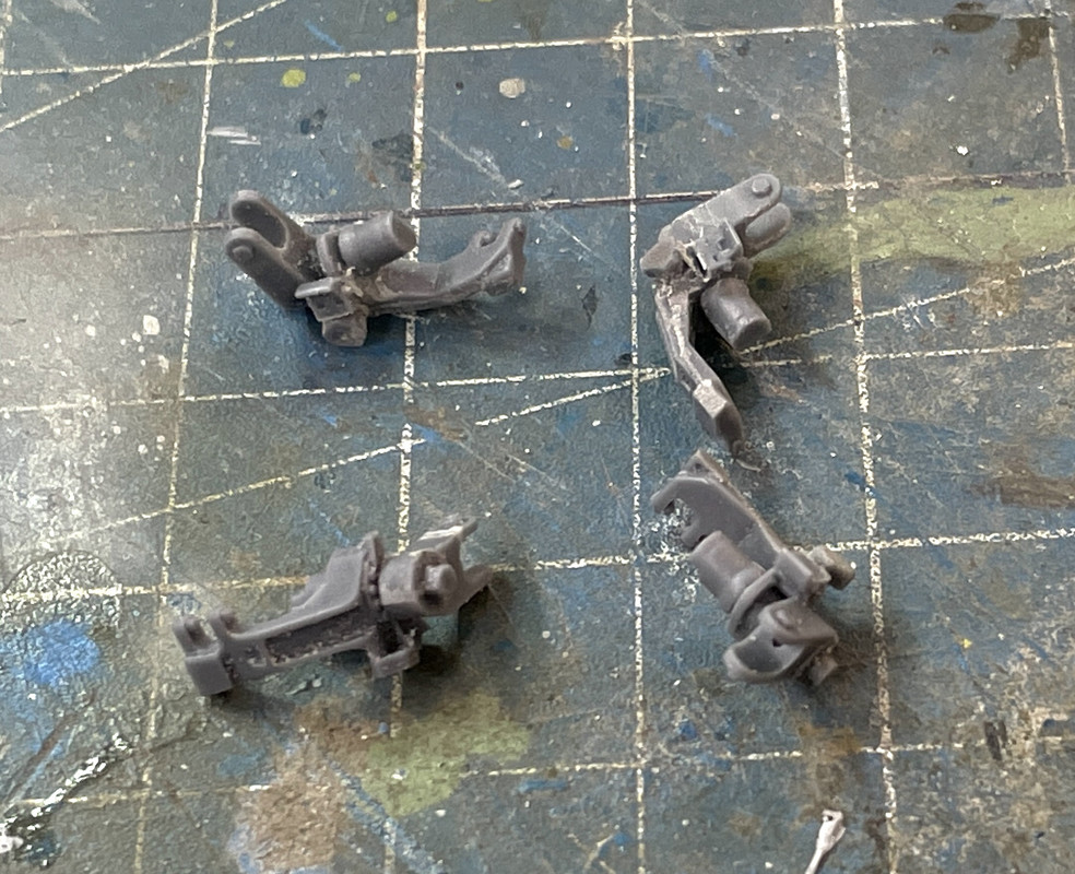
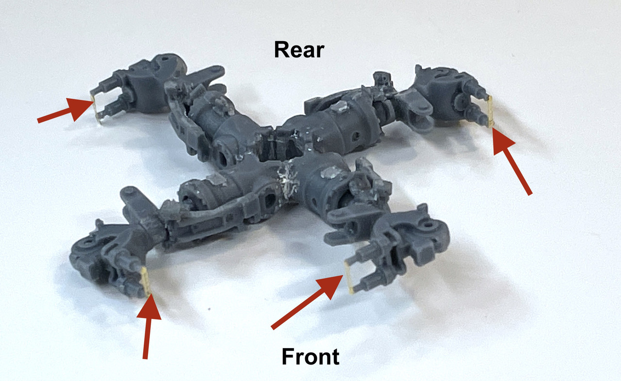
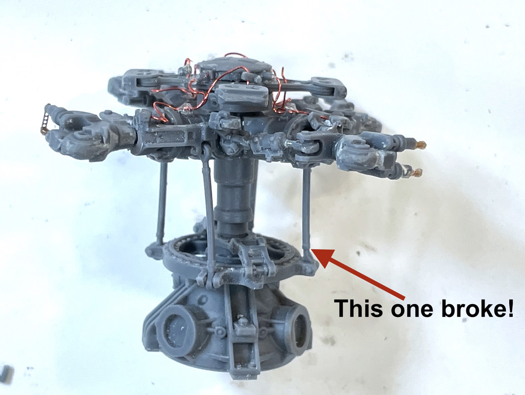
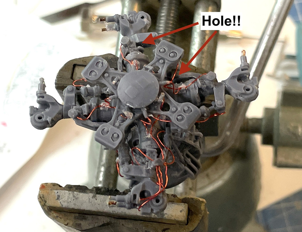
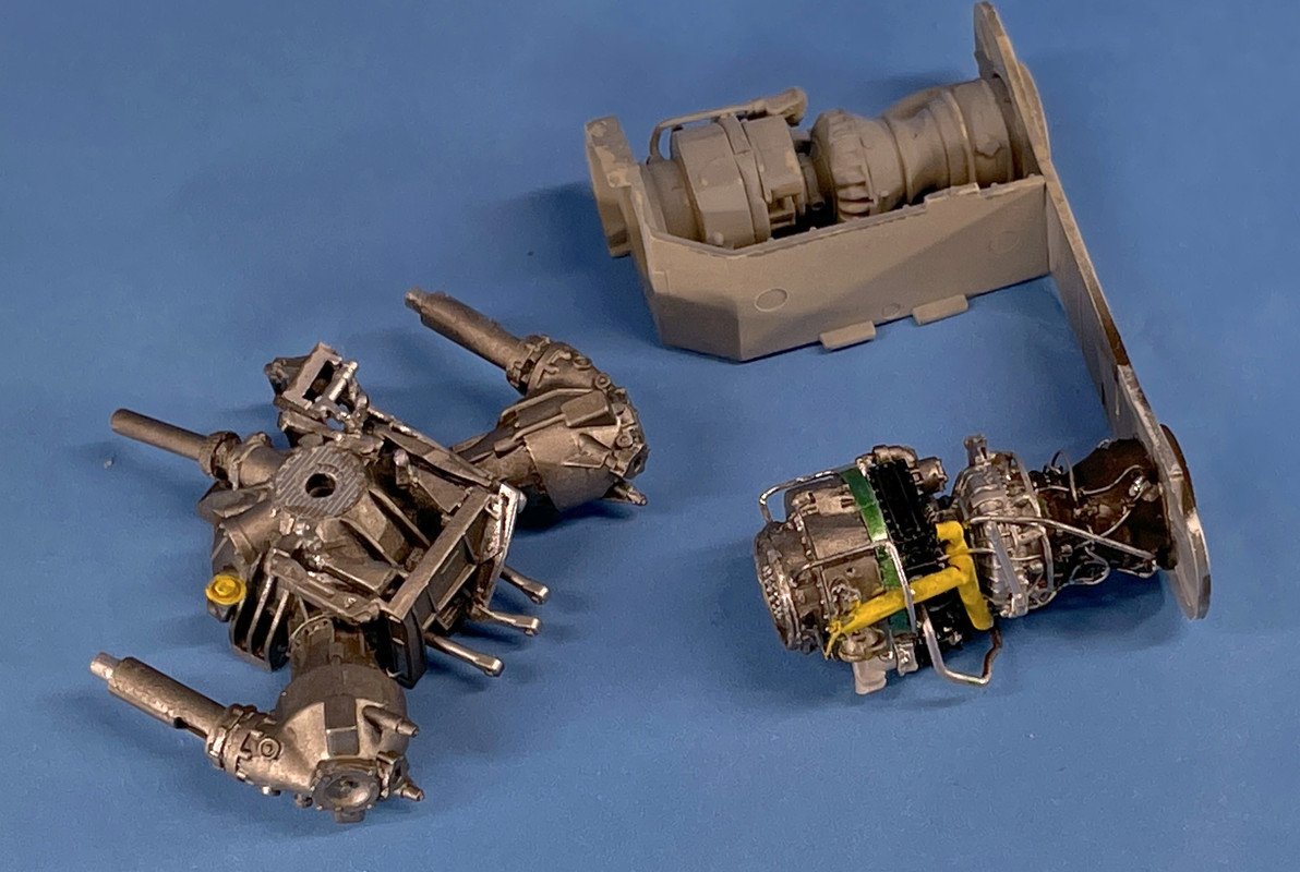
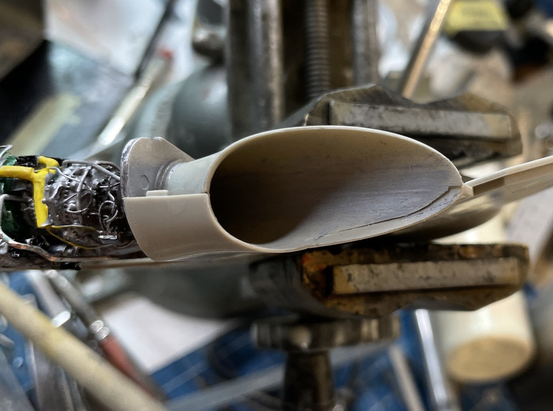
The assembly in the lower left, if you look closely, you can see a white line on on the ear that’s projecting out. That ear broke when I was holding too tightly during the filing operation. I CA’d it back on. It’s not secure. I’m going to add a laminate of some PE fret brass to make sure it doesn’t break again. The resin is hard AND brittle.

3 Likes

Short session so I didn’t paint, but continued with the main rotor. I started to drill the tiny holes for the many hydraulic lines. There’s a mock fitting on top of the rotor hub arms that’s supposed to have 2 lines going through it. I attempted to drill it, but the resin started breaking out. So I filed them off and will make holes clamps with wine bottle foil.

I drill the five holes in the hydraulic manifold fitting on top of the outer arms. That was fun! Not! That’s my thumb for scale. I’m going to lay in these lines now when I have easy access to the holes. I will cut them to length upon final install. I may drill and pin some of the actuating levers too for a more permanent construction.

The rotating portion of the rotor hubs went on next and I found that I glued that little shoe thingy (technical term) in the wrong place facing in the wrong directly. I now know why they gave you 8 of these things when you only need four. They get lost really easily. They can also foul the fit of the rotating portion from seating properly in the hub arm. I had to removed two of them (broke one in the process), glue in the arm and then put the shoe back on.

There are rights and lefts of this rotating part and you need to pay close attention to their placement when doing the rotor-fold version, which I am. To further complicate things, the two in “front” get canted up 10° from level. I set up the level on my iPhone at 10 degrees to use as an approximate guide.

The last thing that went on in this step was a tiny piece of PE. In the real bird, this bar indicates clearly when the lock pins are engaged (in) or disengaged (out), so it can be seen from the ground easily. Since I’m building it with the blades folded, the pins would be in the outward position as the part was molded. You’re instructed to cut them off if you’re building with the blades in the operating position.

I found the easiest way to put these on was to lay them face down on the little piece of plexiglass I use when cutting PE, put a small amount of gel CA on the pin ends, and then bring the pins down to the PE until it grabs. Trying to hold the PE in aligment with tweezers was an exercise in futility.

I’m going to pre-drill any hydraulic line holes before assembly whenever I can.

3 Likes

Not sure the RezKit rotor head is worth it. To me, it doesn’t look that much better than the kit parts and seems like a real pain in the ass to build. I’m sure it will look amazing when done though.

You may be right as you’ll see in today’s post.
Hope everyone survived Thanksgiving day! Our son and family were in from State College, PA so it was the first time the cousins saw one another in over 2 years. When kids are in their teens, two years is a whole lotta change, you know. It took a day for them to get comfortable with each other, but they all warmed up.

First thing I did today was to throw a coat of rattle can Tamiya Silver leaf on the T700 for the first metallic coat. I let it dry completely. It already looks better. I masked the firewall so I would have to repaint the Ocean Gray.

The rest of a reasonably long work session was wrestling with the main rotor resin kit. Let me tell you, this is a real beast. I was spending as much time cobbling together repairs as I was building the assembly. There is a link with a universal joint on one end that seems to be part of the collective pitch mechanism. It’s a two-part affair, with the cylindrical main part and another that will have a hydraulic line in it.

The cylinder casting was a total bear! There was an air bubble flaw in the narrow portion connecting it to the eye clevis on one end. This bubble caused a failure of every one. They gave six of these and I used all six. I ended up drilling and using guitar string to attach the parts back together.

To complicate things more, the eye angles were not in line with the cylinder main axis. I ended up first gluing them in the wrong angle since there was really no way to tell. To get the assembly right I broke the joints so I could rotate the eyes around the piano wire and get them together. It was a half-moon hole in the hub to accomodate the same shaped pin, but of course the pin was slightly oversized and needed careful filling so it would assemble without excess pressure that could break more piston rod joints. Ask me how I know this. After each was in the best position I used med CA with accelerator to fix them.

Through all this manhandling the little PE straps came off and some of the pins to which they attach broke also. I replaced one with 1/32" phos-bronze and will do the same with the other broken ones. I have extra PE parts and will replace them AFTER all the pieces are together. The resin is quite brittle. My 3D printed parts are tougher.

Meanwhile, I wised up and drilled as many of the 0.012" holes as I could before getting these parts attached.

Then more troubles cames. The main shaft was still too tight a fit into the hub for my comfort. I didn’t want to have to press too hard to get these together for fear of breaking more stuff in doing so. To rectify this I attempted to chuck the shaft into my DeWalt and spin it so I could sand it round. That worked until it didn’t! A little too much side pressure and the smallest part of the shaft fractured. That part disappear into the ether. I found that the diamter was really close to 3/32" so I replaced it with a piece of tubing of that size. This worked pretty well and I dodged another bullet.

There is a hydraulic distribution component that sits atop the main shaft and this part has 8 fitting that needed to be installed AND drilled 0.012" The kit had two extras of each type (straight and elbow). I drilled them BEFORE separating them from the mold sprue. That part worked. What was less successful was getting them attached to their respective holes in the distributor. The holes were slight undersized and in pushing them in I broke a couple and lost more.

I opened these holes to a #58 drill to give more room. I still lost one elbow — and that was with my parts capture apron in place — so I started to scratch-build a little soldered affair that needs one of those small holes for a hydraulic line. It’s a small piece of Albion tubing and a 1/32 piece of phos-bronze soldered together. I was in the midst of drilling the hole when it was time for dinner.

Just for scale, that large wooden log is a toothpick! That drill is really freaking small! The 0.012" is holding up much better than the 0.010" ones I was using (and breaking) before.

2 Likes

Great work, but I will stick with the kit rotor head parts.

Gino, that’s why all this crap is sold as aftermarket. It’s personal choice at work.

I put the first color coat on the engine. Tamiya Dark Iron. It’s a little dark so I might dust it with some orangy shade.

Then I got down to business and finished the mechanical assembly of the rotor head proper (not the gear box which is another model in itself) and started piping.

The swash plate and locking lugs that connect it to the rotor shaft was reasonably sane except for breaking the ball end of one of the connecting rods. Again, I drilled it and used Guitar strings. Getting a bit tired of this. The first three rods when in in 10 minutes. That last one took probably a half hour. The lugs that connect the swash ring to the main shaft via that two-ended forging needed some filing to open up the slot so it would slip over the parts without forcing (which tends to break things).

Got the first pipe in and you’ll notice in this image that I got all four PE rotor lock indicator bars in place.

Piping is going okay so far except for a slight distraction.

There were holes in the top rotor piece that i neglected to open. One of the pipes goes up through these holes and attaches to the underside of the angled fitting. I decided to re-pipe correctly and starting doing this late this afternnon and just got started on it.

And you’ll now notice that some of the bars already popped off. I hate gluing PE with CA! I’ll put some more in once all the handling is actually done.

4 Likes

Piping work on main rotor hub continues. Spent about 1.5 hours today, with over one of those hours spent fixing the fittings on the hydraulic distributor. I used up all the resin ones I had including the double set that was included. The last two that I cut off the sprue were damaged since I cut too close to the part and actually removed some of it. I ended fup enlarging the connector end with some accelerated CA and made them work. Hopefully, when painted, they’ll be okay. Getting the piping threaded under the piece and through the hole wasn’t the big challenge. The challenge was geting the fitting into the holes and holding them there. I also replaced some of the straight connectors.

The next pipes ot go on were the large group that feeds the blade locks, and others that connect to the various components. One pipe comes out of the holes in the ring below the distributor. They were a large hole which I drilled deeper with the tiny drill.

This line curves under the blade angle cylinder — I suppose that’s what it is since nothing actually tells you what all this complexity does.

There are four lines that go to the distribution fitting on the top of the claw (that’s what I’m calling it… it’s probably called the blade hinge. Three go to the claw: one into the back of each lock cylinder, one f the claw, and the last into the back of the clevis. That hole I didn’t pre-drill and had to add it now. It was delicate to say the least!

All of those lines will have to painted black once the hub is painted. Next session I’ll get as much done as I can.

4 Likes

I decided to find out what these parts really were and found the Pilot’s manual for the SH-60B Seahawk. A good, complicated read that I should have review BEFORE doing all the engine piping. There are good images of engine details and components. Here’s the main rotor. The cylinders on the sides of the arms are shock absorbers. And the plate on top with the weights hanging on the ends (which are separate snap on pieces on the rotor kit) are tungsten weights that act as a vibration damping system.

3 Likes

I Can’t believe that this is the 3rd time I’ve written this post. I keep doing something that changes the Safari tabs and I lose the entire thing. I’m going to copy the darn thing so I can retrieve it when I screw up.

I got the rotor piping done today. I did the rest of the arms in the same time as it took to do one yesterday. If I had to build another I’d even be faster. Up the learning curve I go…

I did some more research on the prototype learning about the Biflar Vibration Dampening System on the top of the rotor mask. It uses free floating tungsten weights that oscilate opposing the natural vibration generated by the rotors. The system is dynamically balanced, but the rotors still generate a lot of vibration. With the system vibration is reduced 55% in the cabin making for a quieter and smoother ride.

The engines are fully computer controlled by Digital Engine Control Unit (DECU). This takes all the fuel and engine settings away from the pilot. All they do is put the throttle control on idle, hit start, when it spools up, move it to fly and that’s it. Everything else is controlled by the DECU based on the flight inputs and how much power is needed.

The tubular duct running across the top of the engine is the output from the Grit Removal System. A centrifugal impeller drivers particulates out of the air stream and then a separate blower pushes the dirty air out to the exhaust trunk (a la the Dyson vacuum).

I found more good images for detailing and coloration. Notice how clean it is. The Biflar weights are very obvious in this image.

And this is even cleaner. I think this is a new aircraft. Most is body color, but there’s enough bare metal to add interest.

The rotor system even has a power fold actuator (another hydraulic line).

I broke another blade lock sensor and had to scratch-build the complete part this time. No big deal. I was pressing too hard when trying to scrape a bit of excess CA off some small detail. It’s a complicated thing, ain’t it?

I primed it with Tamiya white primer.

I will be adding more details using bare metal foil during the finish painting time.

While this was drying I started working on the transmission and angle drives. The hydaulic pumps come off the angle drives, not the engines. There were four sub-assemblies requiring tiny resin parts and Gel CA. Not fun! Too small of gluing area and critical angles.

These parts going onto a bracket that attaches to the trans body. This stuff may not be visible unless I open some more panels.

The Seahawk also has an APU that’s nestled between the exhaust trunks that provides starting air and power when main engines are off. The kit does not have this, nor are there any AM parts. I suppose I could draw it and 3D print it, but then I’d have open another panel. I don’t think I’m doing this.

7 Likes

The transmission and final drives are built and ready for paint. I kept breaking off the little actuator ball ends and ended up pinning various parts in place so I wasn’t just relying on CA.

The lever bracket had a square opening that you needed to open. I missed it at first and was having a heck of time getting the lever set to fit in. I then saw the little “Cut” writing on the rectangle, removed it and the lever went in without difficulty.

Lots of other stuff went on this final drive including an oil filler which is also pinned.

The angle drives that come from each engine have a right and a left. I didn’t pay attention to this! I didn’t read the instructions carefully enough to realize they had two different part numbers. So of course I put them on backwards (Darn Murphy!!). I was able to pop them off and put them on correctly.

I took these pictures with the trans and engines in relatively correct positions. I think they’re upside down. The tail rotor take off is there too.

Painting will commence again tomorrow.

5 Likes

Looking good. I don’t know how much of the linkages will show, but they look pretty nice.

I may open another panel so they can be seen…

Trans is finished and I painted both it and the T700. Still have to paint the rotor head (tomorrow). Armed with my engine pictures I painted the different engine sections various shades of metal, plus some transparent green metallic shade for the grit separator scroll. I then picked out the various piping/wiring/sensors and appliances in flat aluminun, flat black and Molotow Chrome (decanted and using brush).

The darker shade is flat aluminum mixed with flat black. The lighter shade for the accessory case is flat white and flat aluminum. The compressor section was the initial silver leaf spray brush coated with Tamiya flat clear.

Lastly, I also sprayed the trans with the silver leaf and then went over most of it with the darker black/aluminum mix. I left some parts shiny and painted the oil filler cap yellow.

Just for reference. here’s the engine pic that I used for color choice.

7 Likes

Looking really nice with the paint added. The engine really pops now.

It certainly does. Today the intake trunks were installed along with another piece of skin. I then did the detail painting on the rotor, but there’s still more to do there.

The trunks had a very narrow gluing edge. I spent time finishing the outside edges, but you don’t see that. What you do see is the inside seam looking up the trunk. That doesn’t matter either since the spliter and intake protector block off any view lines. I needed to give a little clamping assistance to make sure that all the seams were down tight.

The angle drives needed to be detatched from the torque tubes to fit them into the airframe. In all these images, neither the trans or the final drives are actually glued in place. The unit is upside down in these two images.

While this was setting up, I went about painting all the details on the rotor hub. I used Bare Metal Foil brushed aluminum for the main shaft. I picked out some of the mechanicals with my dark galvanized mix (steel) and flat aluminum. I then used NATO black to paint connectors and piping. I used Molotow chrome on the snubber rods.

Lost another one of those %&$#()%$@ brass straps. I don’t have more. Will have to make one out of PE fret. Bummer!

The rotor is gloss coated so I can use some Tamiya Panel Accents. They don’t work well with a flat finish. I also need to pick out pipe fittings with gold (Brass) and further age the unit just a trifle with some pastels. Some of the hoses are not black and I will make those additions as I go on.

Here’s a status shot, again, not finally assembled. I also treated the engine compartment walls with some brown panel accent, and a mixture of black and rust pastels to simulate the heat damage to the walls as seen on some of the pictures.

5 Likes

Top notch work! The detail is really starting to pop out now that paint is down. Keep these updates coming, it’s a pleasure to follow along :+1:

Marty

Thanks and I certainly will!

The main rotor is pretty much done. I did more detail painting, painted the white patches on the distributor, added some bright brass at the pipe ends, added some panel accent block in some strategic locations, and painted a single pipe to the snubbers a blue that matches what I’ve seen in the pictures. The ResKit was challenging and at times, so daunting that I wondered if it was worth it. That said, the results are definitely worth it. If you can stand breaking more than a dozen tiny carbide drills and lots of CA gluing frustration, I would recommend it.

Here’s a side view.

There’s one more line that goes on after the blades are installed; the nitrogen leak sensor line that goes to the spot of the arm where the other half of this line was previously installed.

Just for comparison, here’s the real deal showing that blue line going to the snubbers.

I could still add some more metallic accents to the tubing clamps. I’ll see what my mood it…

The intake fairings didn’t fit well over the ResKit’s angle drives. They are bigger than the kit’s I think. Some selective shaving took care of it, but if you’ll notice on the above picture, the fairings DON’T full close the drive housing openings. The instructions DO NOT clearly show this and I was attempting to get them to fit.

Here’s the rubber-band clamps getting it all together, but now I have to go to the shop to see if I glued the forward part in error. Here’s the rubber-band clamps getting it all together, but now I have to go to the shop to see if I glued the forward part in error. Nope… not an error. Here’s the fit. Again, instructions do not tell you how this should fit. That acts as a splinter to not injest boundary air, also gets some cooling to the trans and final drives.

4 Likes

The rotor head looks very nice.

Thanks Gino,

I wish Tamiya made this kit! I’m having trouble with some of the fits and the aftermarket stuff isn’t helping. I spent a lot of time today, filling gaps and preparing the surface after that activity. I was unsure about how the intake fairing fit and my suspicions were well-founded since the engine hatch didn’t fit well and needed a piece of fitted styrene to fill it. Later on I checked the entire assembly onto the fuselage roof and the fit there was quite challenging. It’s going to require a shoe horn and some patience to get it settle down as it should. That step is very late in the assembly and that, unfortunately could make it more difficult. There are two slots on the fuselage top that mate to two tabs on the inner engine compartmemt walls. It’s a blind joint and would really benefit by having your finger pushing up to engage the pins. But… you won’t be able to do that because the cabin will be installed and nothing will be able to get in there. It may be better to just cut off the tabs so nothing has to go into blind slots.

I didn’t like the obvious seam running down inside the exhaust stacks so I filled that with Tamiya putty. I used some adhesive backed sand paper wrapped around a paint brush handle to sand it smooth.

I used shaped styrene to fill the intake fairing gap.

I then finished it with a bow-sander with fine grit. I had to re-engrave the seam lines. I used masking tape to protect the surfaces around the fill to not do more damage.

There is another fairing that encloses the other half of the exhaust outlet. It too has some more seams that needed a little help although nothing to the extent of the intake gap.

I again used Tamiya putty to fill and the sanding bow to level it. Not only was there a gap and I also got a significant glue smear resulting from putting the liquid cement in the back, but having it wick out the front under my thumb.

Here is the sanded version.

Lastly, some PE and some antennas and such went onto the engine housing roof.

Y’all have a nice weekend. We’re due for some strange and rare weather tonight and I’m not happy. There is a significant tornado threat all night long as a major cold front crashes into this unseasonably warm weather we’ve been having. Most of the most agressive parts is supposed to be west of Louisvile, but you never know. I don’t like tornado threats!

4 Likes

Yup, the whole engine/rotor assembly is tight on all their H-60 kits. I cut off all the locating tabs and it is much easier. I also started building it from the bottom up on top of the fuselage, as opposed to a separate assembly that you add on top as the instruction show and it seems to fit easier.

1 Like

Amazing work and workarounds. Needless to say, I really like that rotor and engine compartment assembly.

Stay safe and batten-down the Kitty Hawk.

1 Like