I have to agree that a Tamiya kit of this subject would be really welcome - their engineering and fit are typically perfect even if their level of detail isn’t as high. With Academy’s 'Hawks obsolete and Kitty Hawk out of business, my wish is that Tamiya or another mainstream company kits some more 'Hawks in 1/32 or 1/35 styrene. Or maybe Gino could convert one of the existing kits - modeler’s luck says that’s a sure way to get a company to kit it for you.
1 Like
There is a rumor that Trumpeter bought the molds. We shall see. I would rather not a Tamiya version myself since it will be sparse on fine details. I actually like the Kitty Hawk kits. With a little bit of work, they can come out really great.
Or maybe Gino could convert one of the existing kits - modeler’s luck says that’s a sure way to get a company to kit it for you.
Been there, done that and still no 1/35 MH-60J Jayhawk model. Well sort of…
Happy Monday. First of all I want to tell everyone that Louisville was spared any damage from the monster storm that ran through KY. Unlike many, I do not either blame a diety or praise one regarding where a weather front decides to become malevolent or benign. It is almost the pure definition of random. it’s that randomness that drives people to want to identify an actor, but there is none. With tornadoes, a house on one side of the street is reduced to molecules and the one on the other side of the street is untouched. Gods have nothing to do with this. What I would want a god to do would be to prevent the storm from happening in the first place.
On Friday afternoon, I listened to a broadcast from one of our local weather forecasters where he was discussing “Athmospheric Caps.” I hadn’t heard the term, but it was very interesting. It is the high pressure that exists high in the atmosphere that can limit the ability of a storm front to make tall super cells. It results from when low and high pressure areas collide and the high pressure rides up over the low.
It was strong over our area and weak in Western KY. He said depending on how long it hangs around, it could mitigate how strong the storms would be over Louisville. I feel this effect was the main reason the storms broke down as they reached our area. Tornadoes did form about 25 miles south of the city. Meanwhile, my trash totes didn’t even move. Others in the Commonwealth did not fare so well and it was horrific in the extreme.
So I am extremely happy that my wife are I are alive and well… that our house is intact, and my workshop is here so I can build this model and write about it to you.
Trumpeter buying the molds doesn’t solve the problem, and they’re fits aren’t do good either. All I know is that I built the Tamiya 1/32 Corsair and barely used a drop of filler anywhere. That’s the standard.
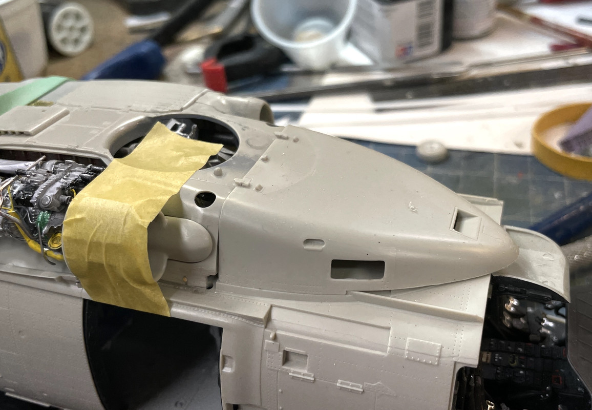
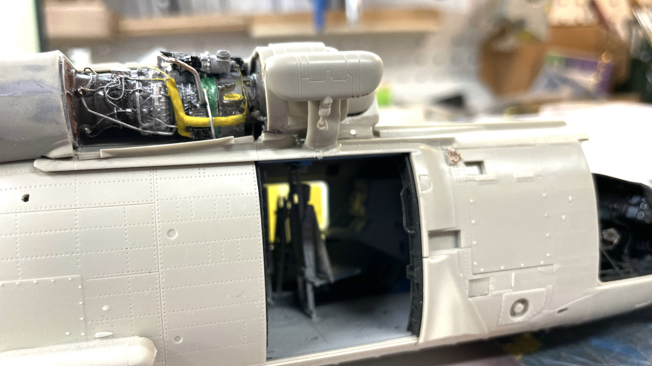
Today began with gluing the interior onto the right hand fuselage side. I used some Quickie clamps to hold it tightly in place. The fit was pretty good so far.
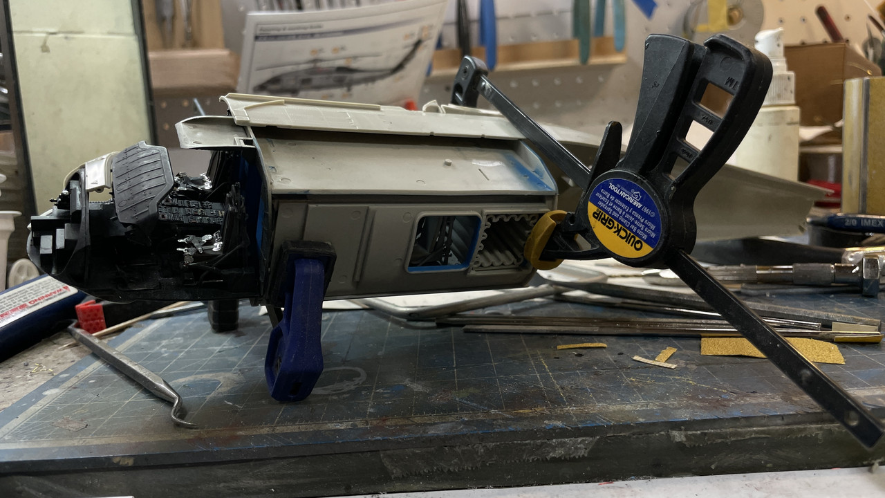
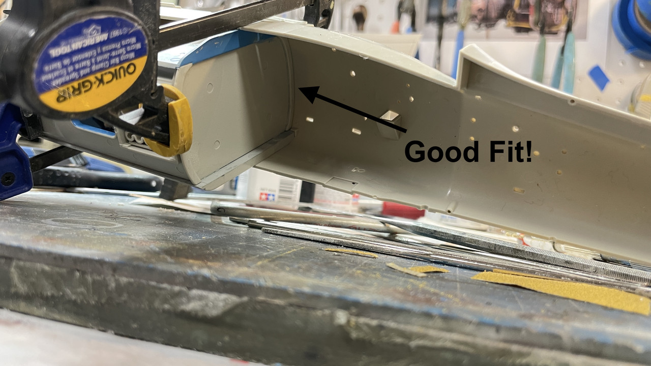
This view shows how nicely the rear of the cabin fit the fuze side. I forgot to put in a piece that lay inside the nose one each side. I had to stick it to a sticky picker and slide it into the narrow space, and glue it. No harm no foul. I did glue it to the other side that wasn’t attached.
I then attempted to fit the left side in place and was greeted with terrible gaps. If I got the top to fit tightly, the bottom was wide open and vice versa. Two factors were at work. With the cabin being a completely enclosed structure, you can’t look and see if it’s aligned properly as you could when it was just on one side, and I suspected that the cabin bulkheads were just too wide in spots preventing closer.
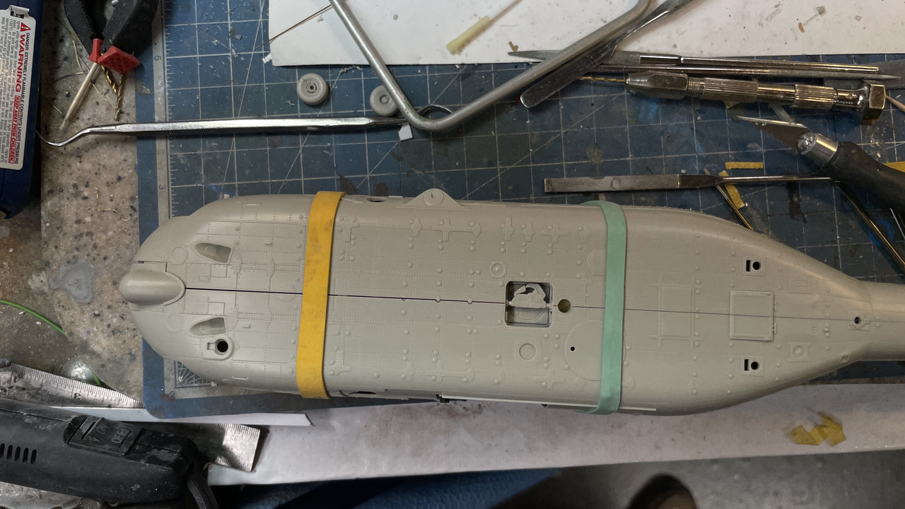
Here was the bottom: Notice the bulb in the front. That was an option that I decided after it was all glued in that I didn’t want to use it since I wanted the FLIR option on the front end.
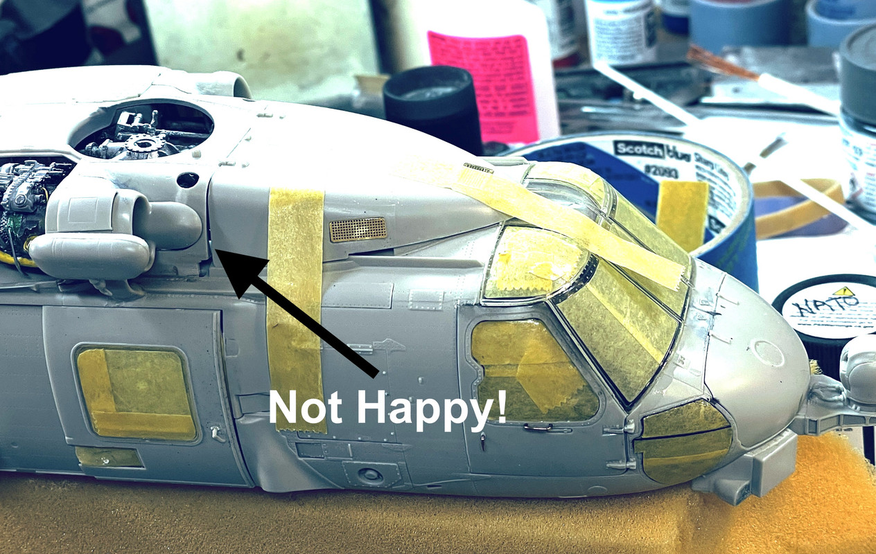
And this was the top! Ugh!
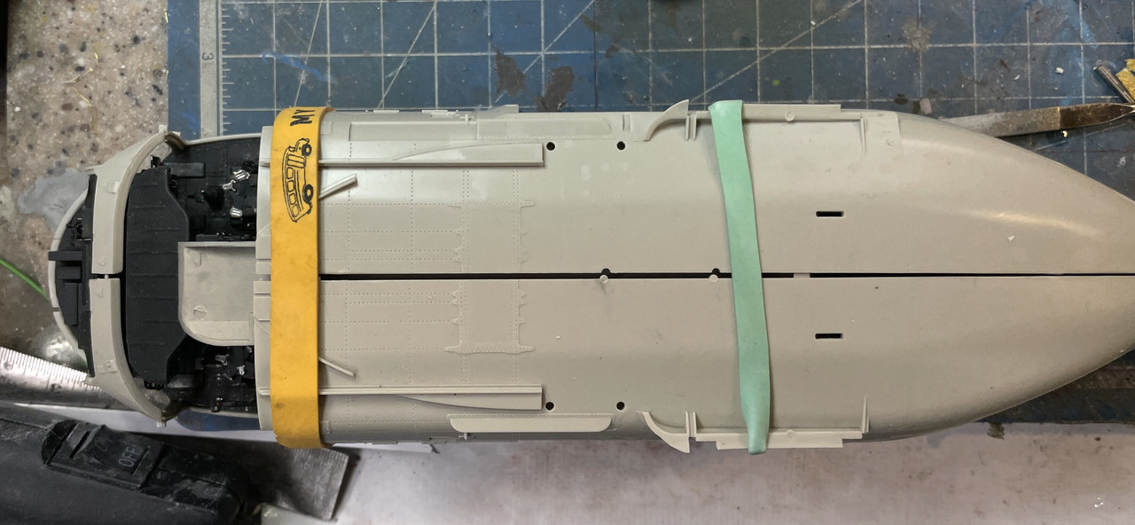
This was totally unacceptable and made for bad fits of the engine housing and the front fairing.
I selectively reduced the outer edges of the bulkheads and kept trying the fit. I finally got it as far as it would go, so it was time to glue. But first, the rear landing gear has to go in because it’s trapped by the two fuze halves.
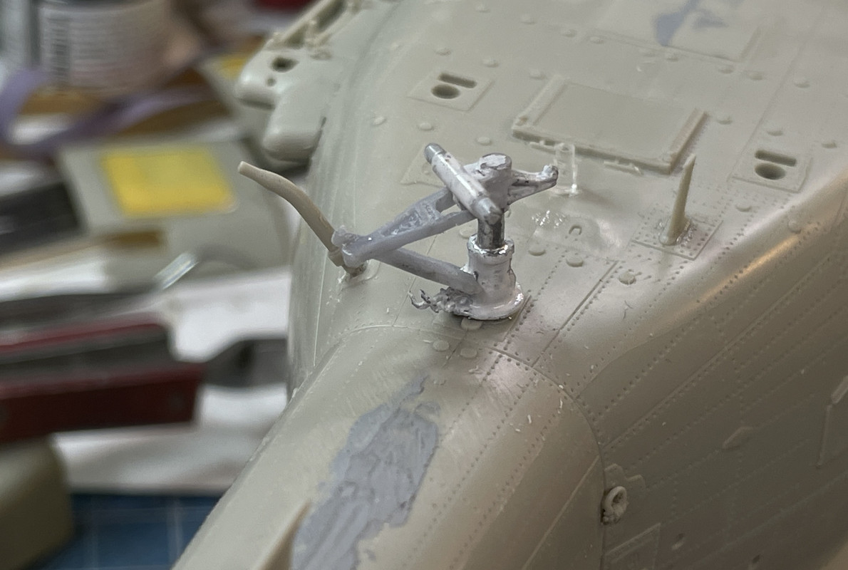
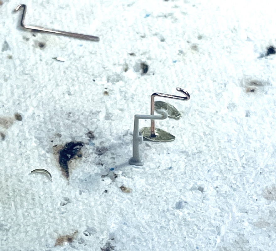
I painted the gear silver only to identiy that it was probably white. I first tried bare metal foil for the oleo strut, but scrapped that and used Molotow chrome brushed on. Meanwhile, the scissors link broke. I glued it together once, and it broke again when I was fussing with the foil. This time I drilled and pinned the scissors joint and glued it again. This time reinforced with thin CA.
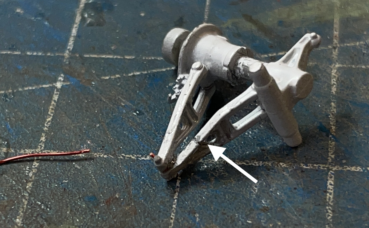
But then, disaster struck again during all my manhandling when trying to close those pesky joints. Another piece of the scissors broke in another place and got lost.
I’ll have to scratch-build or 3D print another scissors. Annoying! My UV 3D printing resin is tougher than styrene… or at least the Kitty Hawk styrene.
I changed out that front piece before commencing the fuze gluing. This one has the mount for the FLIR in front.
It was time to glue the fuze together trapping the landing gear and the front piece. I worked the bottom joint first since it’s exposed more. I let the top joint go for a while. The bottom will get a little filling tomorrow after the joint is fully dry.
The top joint still ain’t so hot, but it’s hidden. It could cause fit problems with engine housing, fairing and the front glazing that I’ll have to figure out as I go.
I’m going to fill this seam with styrene and then filler.
The tail seam was the best of the bunch and looks pretty good. I apply the liquid cement on the inside in as many areas as I can before wicking it in from the outside.
While the paint on the gear was drying I assembled the wheels and made some masks for the hubs. I use a small machinist dividers with one point ground to a sideways chisel edge. I measured the diameter with the digital calipers, divided it in half and used this setting to set the dividers. I added a dab of Molotow Liquid Mask to cover the tiny hole from the dividers’ point.
Fuze cleanup will start tomorrow.
5 Likes
Glad you and yours are ok .
I live at the seashore in the northeast and have had to leave several times not knowing what may or may not be left when I return . I often muse about which is worse - the long agonizing wait while the storm does it’s bit - or the fear that a tornado brings with it’s near instantaneous destruction. I’ve lived the former - I wonder about the latter .
Glad you can keep up the work on your hobby .
Cheers - Richard
1 Like
Glad you came through safely. The fuselage fit is an issue on the KH kits. I did like you and sanded down the bulkhead sides; you can get it pretty close. I still prefer the level of detail on the KH kits, fit issues and all, over any Tamiya kit, but that is just me.
1 Like
Hi,
Glad you are ok.
The crazy part of these kits is that they do fit, yet only when all the interior supports are seriously filed back. Then the connection points on the fuselage skin parts need to be opened wider. Test fit and test fit. I’m sure you understand. Lovely job one the engine and rotor.
Look forward to more and Thank you for the effort.
Thanks Guys!!!
I am persistent and today that persistence paid off. I decided to go for it and mount the entire engine housing on the craft. It took lots of handling, pushing and shoving and if any more add-on details were on the plane, I would have surely broken most of them off.
Before doing this I started working on the major gap issues. For the top gaps I used a combination of strene strips and med-acccelerated CA.
When dry I used a single-edges razor to slice the excess off near the skin line, and then using power precision sander and other sanding tools to level it. This entire joint is buried beneath the engine housing. I also used the razor to scrape the joints, not just rely on sanding.
For the bottom and tail seams I used mostly Tamiya filler and some strategic CA to fill it all. In this case I didn’t use the power sander, but used the bow sander for all the convex curves.
Getting the engine house on required some surgery and lots of pushing and pulling. I though I wouldn’t be able to use the ResKit trans because fit issues, but that was a red herring. The real culprit was the engine itself. It was too fat and was holding the entire assmbly off the plane. I also had to pop off the intake fairing to so more cutting. I relieved the front edges also. I lost the control rods on the trans, but they would be buried under the nose fairing.
I had to grind some of the engine, and cut one of the pipes so the engine would fit properly.
With the interference removed I was able to rubber band and clamp the housing and start gluing all around.
One joint needed some more attention with the addition of a piece of 1/32" rod and CA. That joint, even with removing the interference, was still too high and need persuasion to get where it belonged.
Here are some of the other fits after correction.
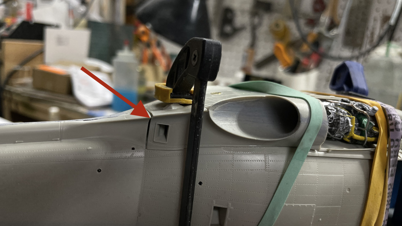
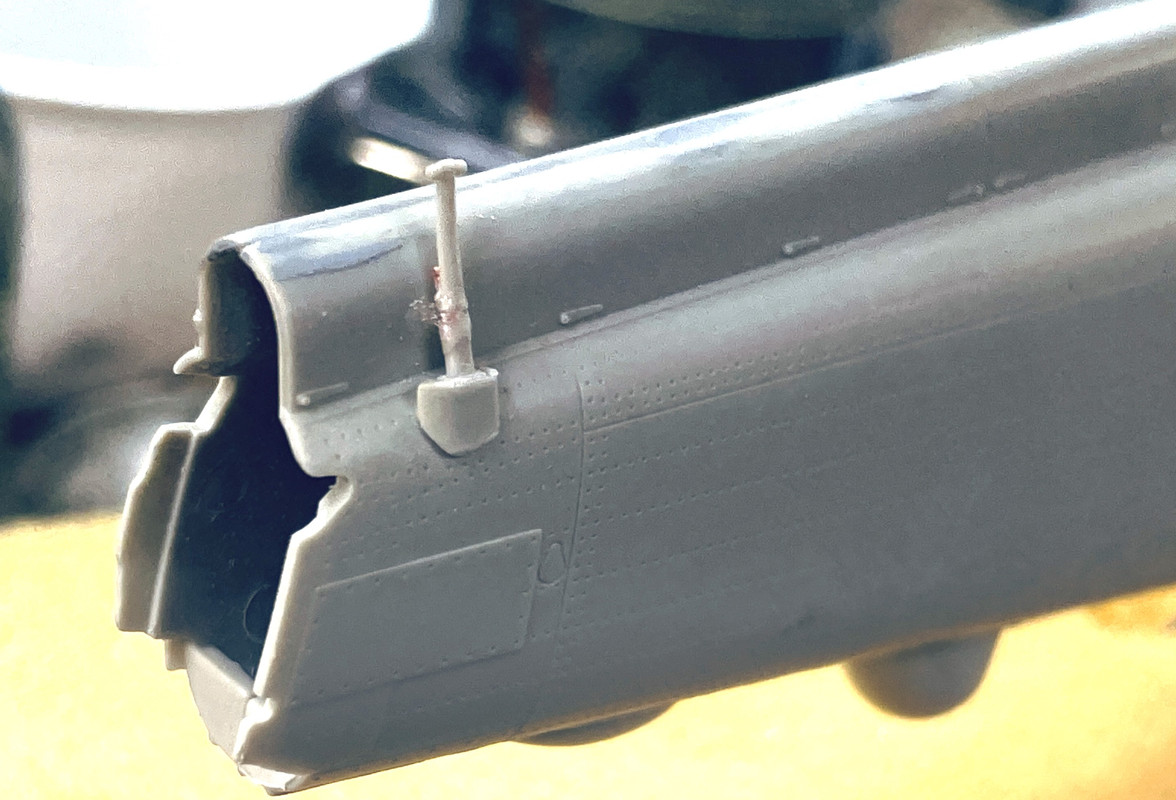
I was rewarded after all this work to see that the nose fairing fit almost as it should. This is not glued. There’s some internal pieces that must go on first. You can see what’s left of that Phos-bronze pin.
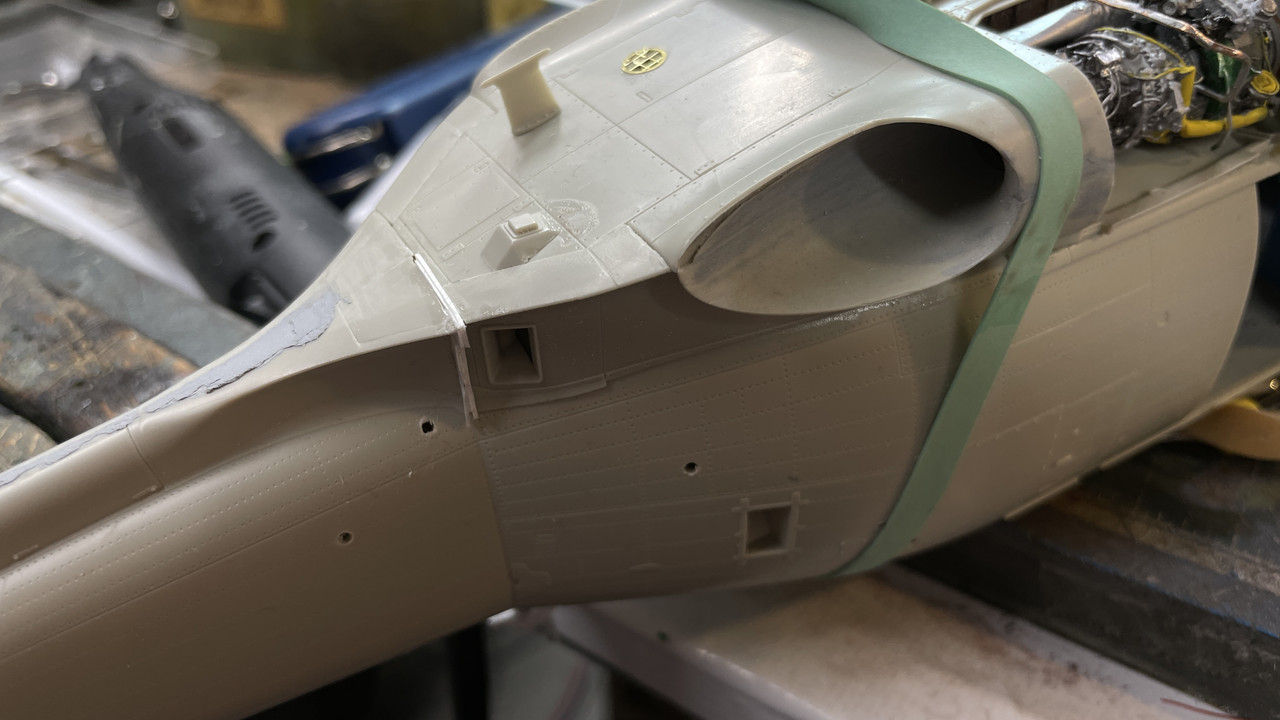
The last gap was due to a mismatch of the fuze sides at the rear engine mount vertical face. I could see this offset, but it seemed in a difficult to remove it, so I decided to handle it with filling.
Again, I used styrene (2 pieces of 0.015" stock) to fill it. It will dry overnight and I’ll sand it the next work session.
5 Likes
Nice work. I dealt w/the gaps the same way as well. The rest should be issue free since you have all the hard parts done.
I would also like to see Tamiya produce some 1/48 scale state of the art helicopter models, and often wonder why they don’t. I know they put out some 1/72 scale kits, but aren’t those all Italeri molds? I think if Tamiya did a 1/48th Blackhawk or Seahawk, they would probably sell.
Thanks! And a 1:35/1:32 version would even be better.
First I unsuccessfully printed a gaggle of scissors links that turned out to be too thin to properly drill for the assembly wire I was going to us. I’m going to redesign.
I then finished cleaning up that complex fill area where the engine house joins the tail section. I used various sanding aids including a riffle file that works on concave surfaces.
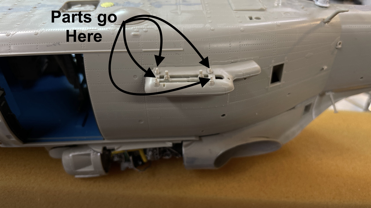
The rest of the long work session was spent installing lots of little bits that make the model unique. The SH-60B LAMPS version has a lot of antenna and sensor sticking out everywhere. I reinforced some of the most delicate with wire. The instructions called for the canopy to be installed now, but I’m holding off until much later. I will mask the interior without the glazing. I also built and installed the FLIR unit that hangs on the front. There are loads of lights on the ship which I install with canopy glue on a surface prepared with Molotow Chrome Paint.
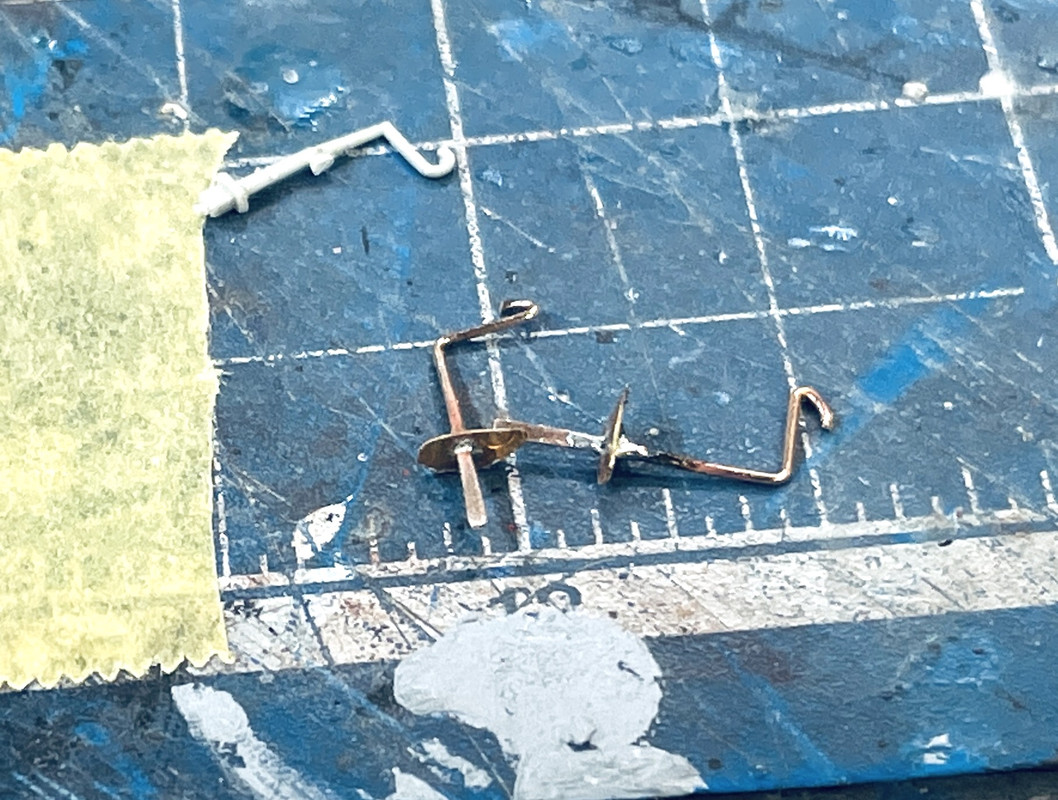
This phos-bronze is firmly holding this protrubing antenna.
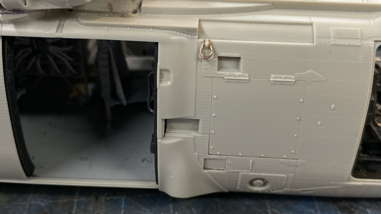
There are two lifting eyes that were broken on the sprue. There are two “E” sprues and the part was broken on both.
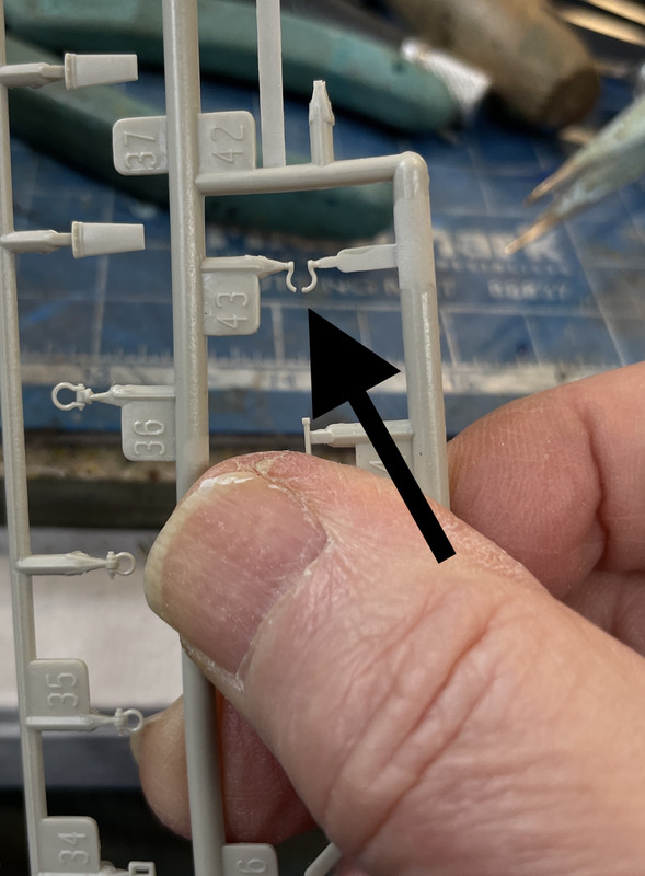
I formed new ones out of wire and installed them with CA. They’re a little thick, but that’s the best size I had. Everything else was too thin or even thicker.
Here are some of the lights. That ugly seam is actually closed with CA. When painted it will disappear… thankfully!
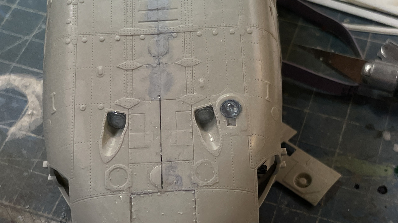
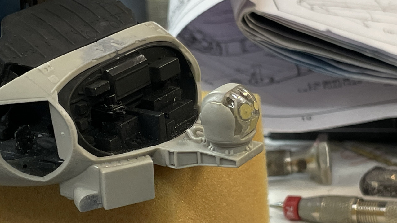
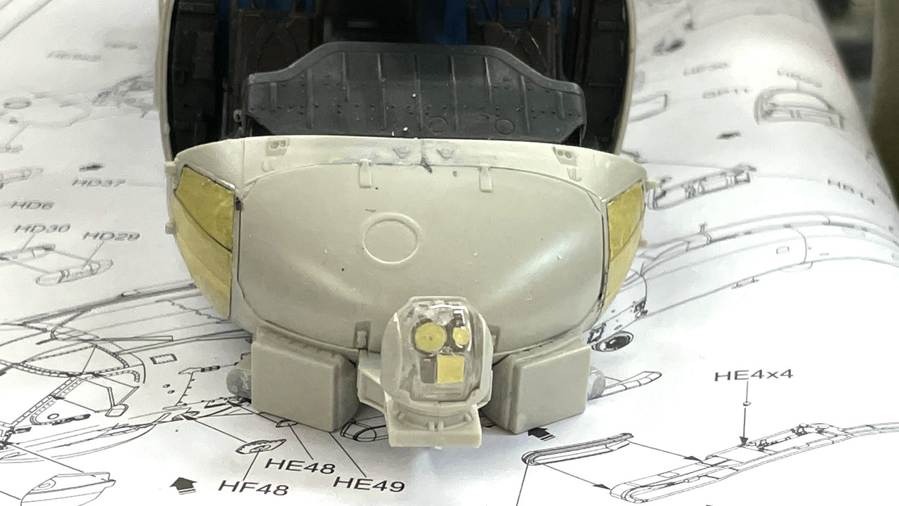
There are sensors that go on the four corners of the cabin. Not sure what they are, but they have lights on the front ones also which I pre-treated with the Molotow. The FLIR goes on an optional bracket on the nose. It even includes some nice connecting leads.
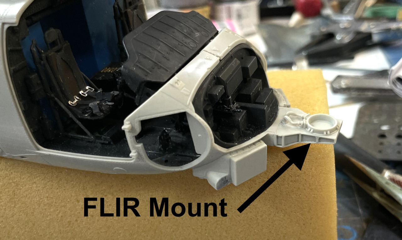
The forward half of the FLIR ball is transparent so I pre-masked the optical windows before attaching to the airframe.
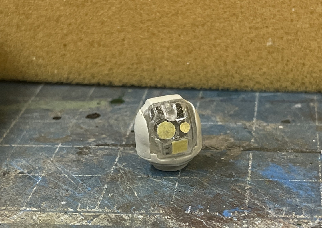
It’s captivated by the two halves of the lower frame. The ball articulates vertically, but does not rotate.
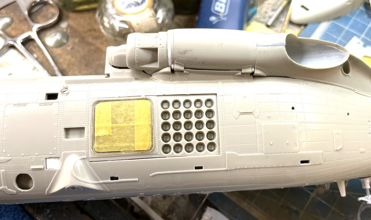
Can someone tell me what that rectangular array is? IFF?
4 Likes
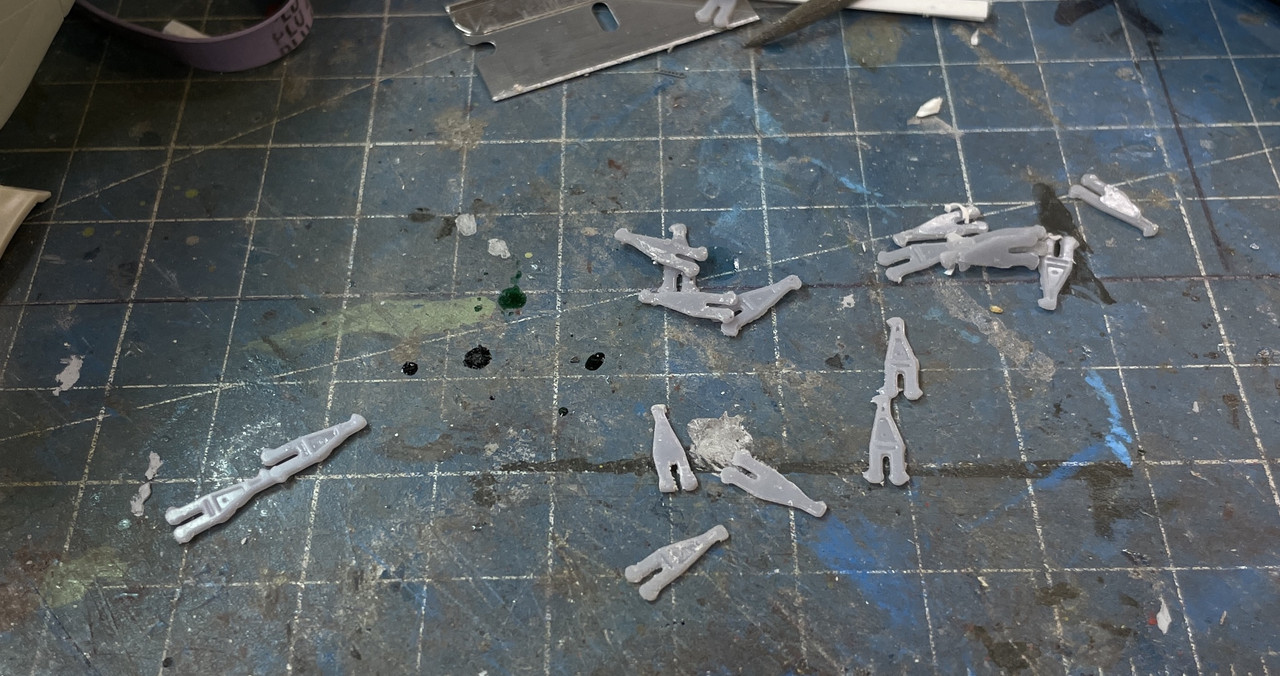
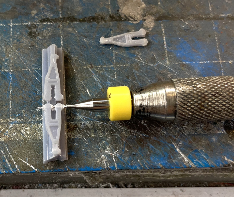
I re-designed the scissors print. Instead of printing them all directly on the build plate, i drew a plank below them and supported each print sufficiently so no part of the link would attempt to print in free space. My reasons for this change are due to the nature of starting layers. The first 8 layers printed are exposed for 60 seconds per layer (as compared to 10 secs/layer on the rest) to ensure that they are well hardened and adhered to the build plate. If not, when the plate lifts to allow fresh resin to backfill for the next layer, the previous layer could adhere to the teflon barrier at the resin vat bottom, and not lift with the build plate thus creating a failed print job. This long exposure has a negative side effect. It causes the first layers to spread out beyond the part’s boundaries creating what’s know as an “elephant foot”. For large parts, the elephant foot’s no big deal, but on small parts it can distort the shape pretty badly as it did on my first attempt.
By elevating the parts off the plate and supporting them, the elephant foot is on the plank, not the parts, and the parts come out true size. Notice that the print was actually starting to faill on the right side of the image with the plank lifting off the build plate, but enough of the plank was still attached to produce a bunch of good parts. That’s why I ALWAYS print a lot more parts than I actually need. The resin is cheap for tiny parts, and the print time is the same since it’s the number of vertical layers that determines print time (along with exposure times and print layer thickness).
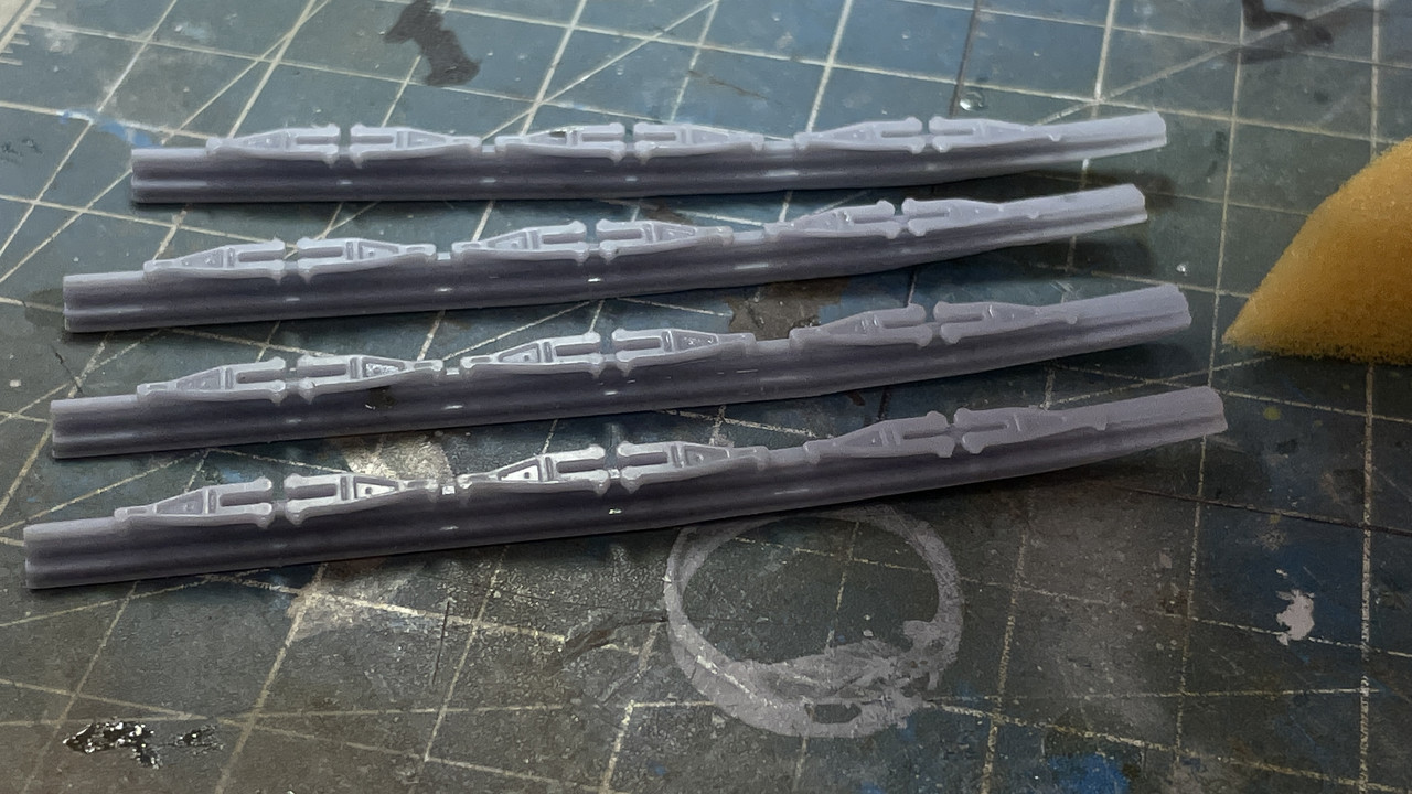
I post-hardened the bars before drilling the holes and separating them from the bar.
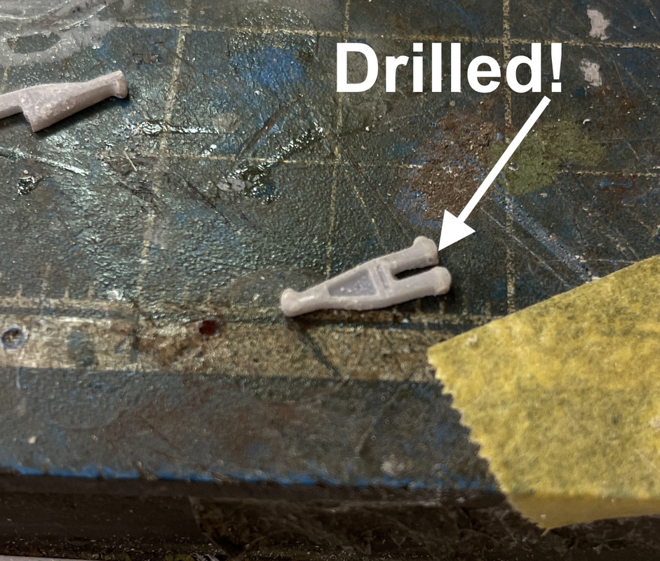
I tried to drill one and did have success. THEY WILL WORK! Notice the one in the background has a broken leg. Again, that’s why I print so many. They’re fragile and drilling is a bit abusive to tiny parts.
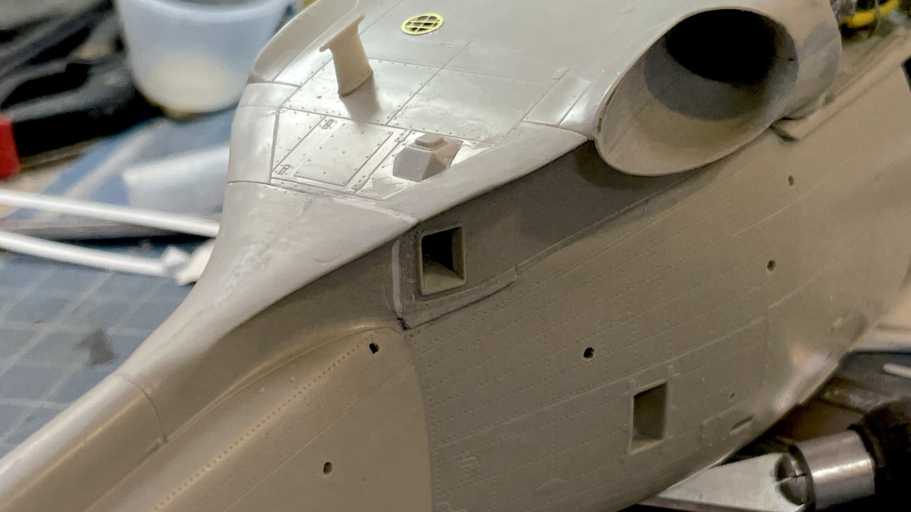
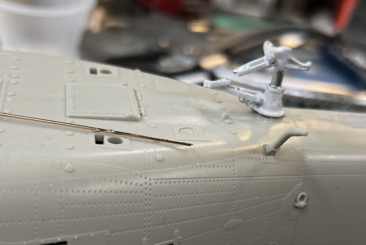
Work continued adding fuselage details. There were three antenna that went onto the tail boom. I had pre-opened holes for two of them, but had missed opening the square hole for the middle one. Rather than just drillng anywhere, I came up with a scheme to shine my iPhone light down the boom and lo and behold, the thinner plastic where the location was on the inside glowed just enough so I could poke the hole from the outside and produce the square hole in its correct location.
The crew door is supposed to be installed now, but I want it in the open position to pose a mechanic sitting on the sill. That means the fuselage must be painted before the door goes on since you can see the fuze wall through the glazing. I also drilled and pinned the delicate door handle. I have the Eduard transparent parts mask set for this model. I use the Testor’s Canopy Glue for all the transparent parts.
Up next was the torpedo rack on the strb. side. It’s a 3-piece affair where you have to sandwich a part inside before gluing the two halves together. It was confusing to me just how this part was to be installed so I spent a lot of time studying it and ultimately got it right.
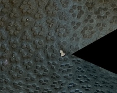
Onto it when four, very tiny sway braces. These suckers were really, really tiny. I used a ‘parts catcher’ apron (a la watchmakers) stapled to the underside of my work bench that catches about 80% of the crap that I drop (as long as I remember to clothes pin it to my shirt). One of these parts dropped into it. Here’s what it looks like. Imagine seaching the floor for that!
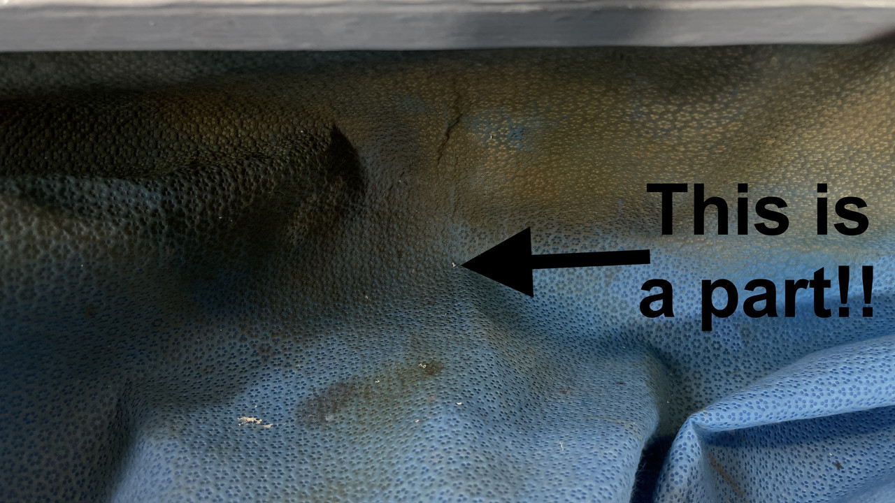
In case you think I’m being hyperbolic, he’s a cropped closeup showing it’s actually a molded part.
And here they are glued in position on the underside of the torpedo rack.
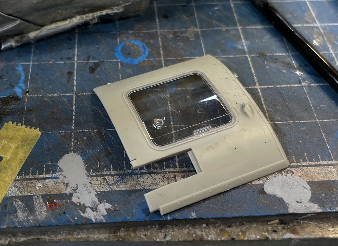
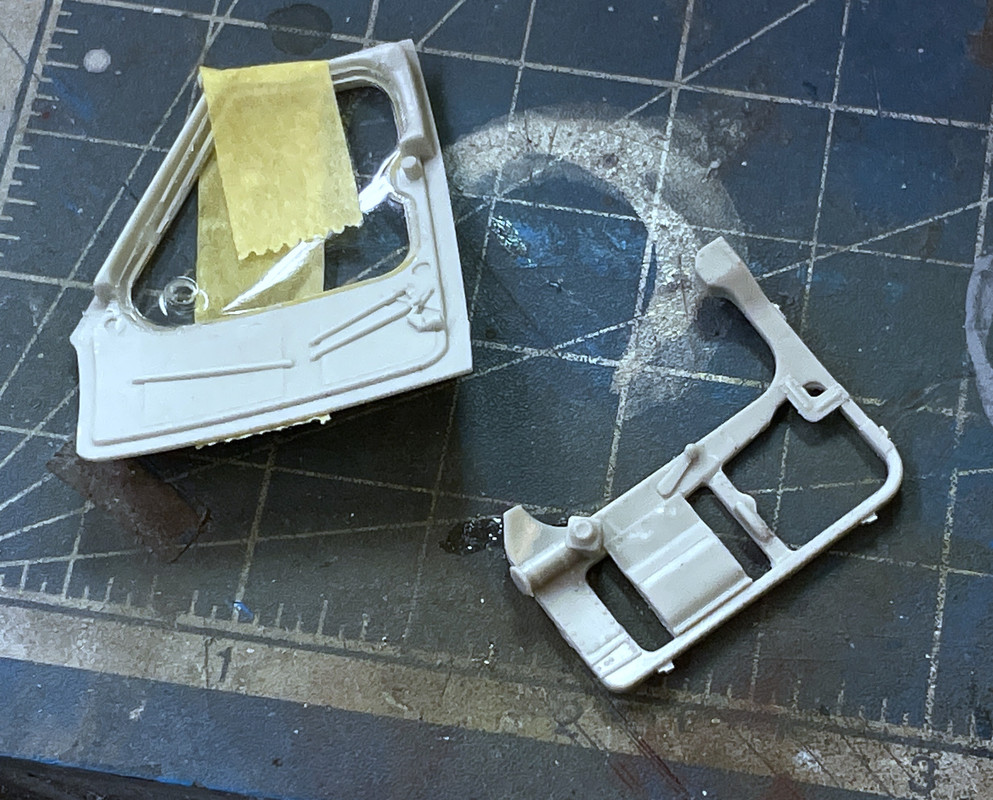
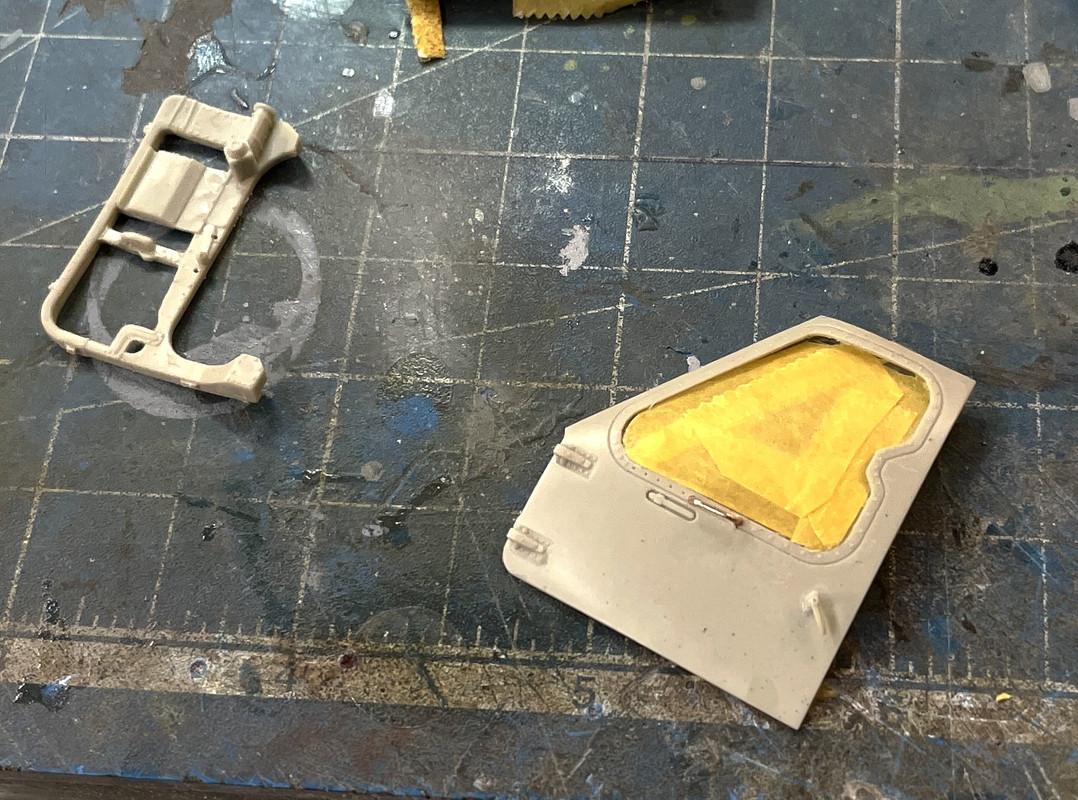
Last thing I did was assemble the co-pilot’s door. Again, I have to hold off on the full assembly since the inside of the door is black, like the interior, but there’s a inner frame that goes on over the glazing, making painting and masking more complicated. I’m going to mask the glazing inside and out, paint the inner wall, then assemble and paint the outer frame. I looked to see if it was possible to open the door, but it’s not going to be very straight forward since half of the hinge is molded into the fuze wall. I it could be cut out and glued to the door part it might work. I think about it.
Until next time…
3 Likes
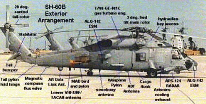
Coming along nicely. The square sensors on the nose are ALQ-142 ESM (Electronic Support Measure) sensors. It is part of the Light Airborne Multipurpose System (LAMPS). The ALQ-142 is data-linked to the shipboard SLQ-32 electronic warfare (EW) system. In its primary anti-submarine warfare (ASW) role, the system extends a fleet’s surveillance range by acquiring a hostile submarine’s radar emissions and determining its bearing.
This may help for other sensors on the helo.
2 Likes
Thanks for that Gino. I went on line and did some more research on the ALQ-142 EMS, and it’s quite a package. Seems to be able to do everything. That craft has one bucket load of avionics.
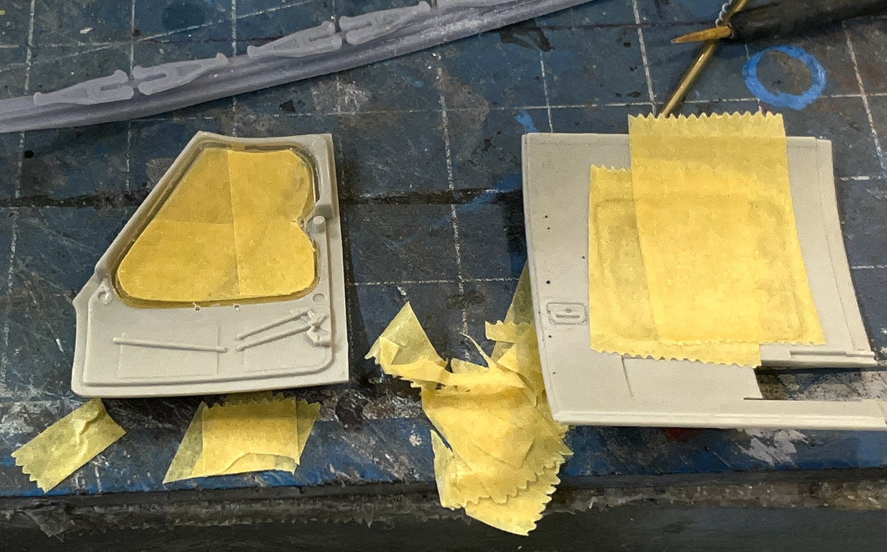
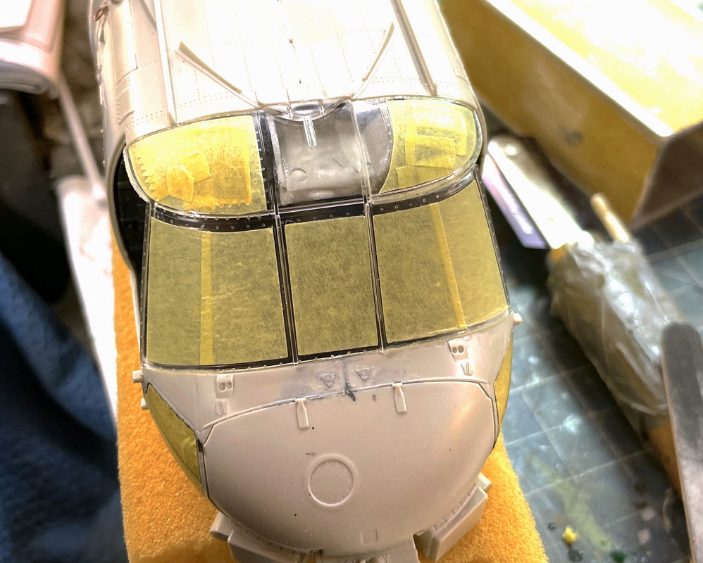
Started masking the various glazing needed to do the early painting. Then I found that the Eduard masks for the MH Blackhawk don’t actually fit this version, as seen here.
If I’m going to have to add more mask to fill out the spaces, I might as well mask from scratch, which is exactly what I did. This was the exterior of the glazing.
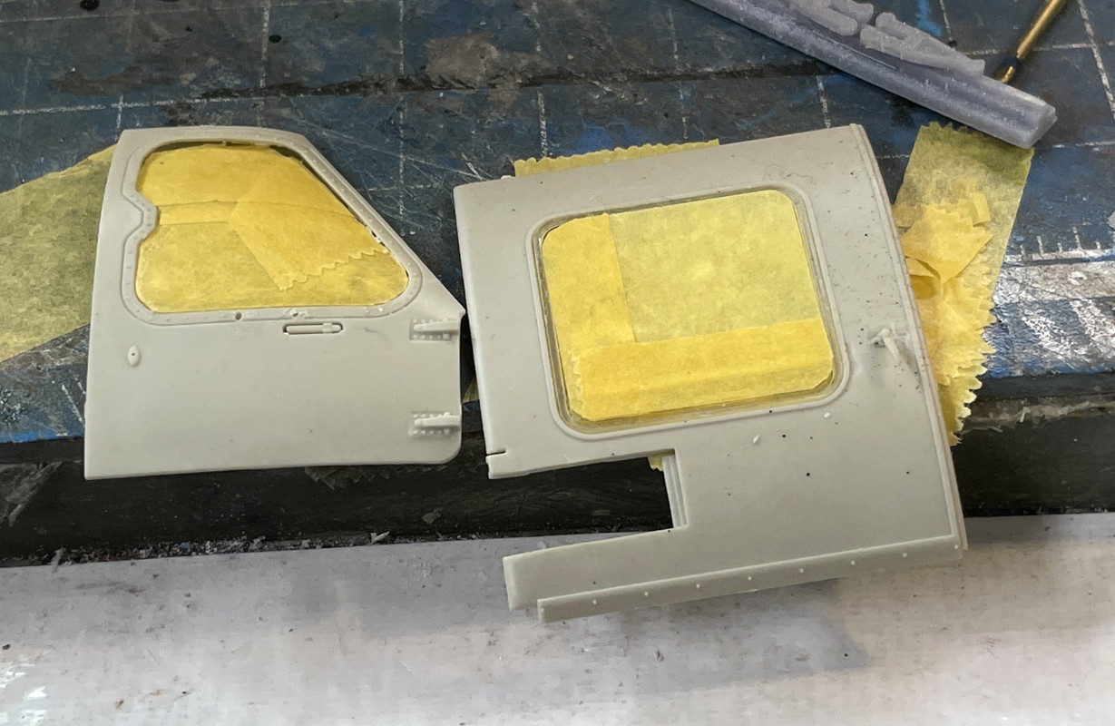
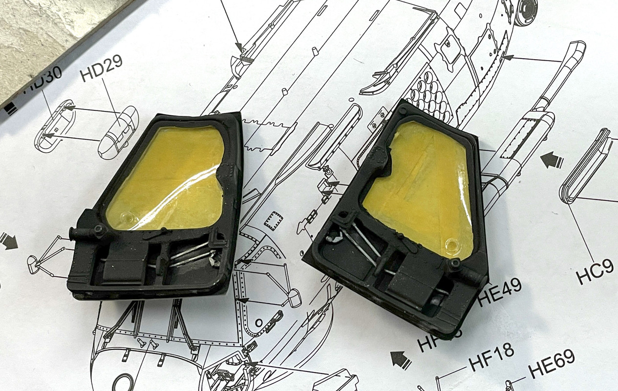
And I masked the interior too. The sliding door interior will not be seen, but the cockpit doors are viewable and will be painted black.
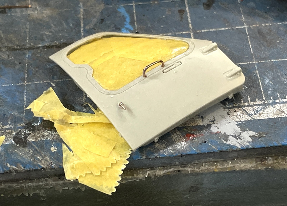
I also replaced the plastic door pull and the missing door handle with metal parts.
Lastly I spent a lot of time… to darn much time on making the scissors links. Here’s me cross-drilling the link. My drawing was a little off making the legs too thick. In attempting to open up the gap I kept breaking the legs. I also broke a ton of these drills for various reasons including putting side pressure on the drill and actually bummping something when I put it down on the bench.
I ended the session without finishing this. At least I can print more. I’m post-curing one batch for the second time to maybe toughen it up a bit more. Not too much production for an afternoon’s work.
3 Likes
Finally got a reasonable scissors link installed. I don’t really like it, but I’ve spent WAAAAYYY to many hours screwing around with it. After breaking a half dozen micro-drills at a buck fifty a pop, I didn’t even pin the darn things. I just CA’d them and that’s that.
Tomorrow is Christmas Eve. Everyone have a wonderful one!
3 Likes
Happy Monday after Christmas.
Odds and ends day. Finished masking the cockpit doors, hung the personnel hoist, prepared and installed the corner cockpit windows and the nose skin, and installed the outer wall that covers the sonar rack.
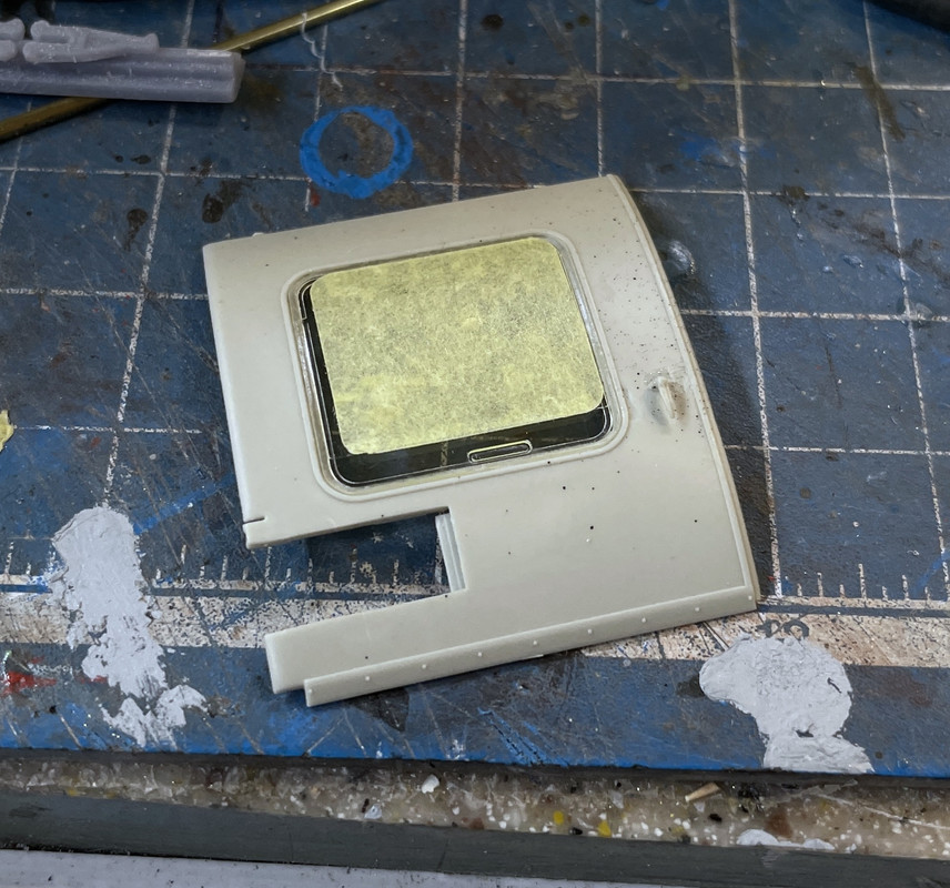
Again, I masked the interior and exterior of the cockpit left door, sealed all the edges with clear gloss to prevent color leakage. And again, made the hand pull out of phos-bronze wire. Since the metal stuck through the other side a bit, I drilled holes in the inner frame so the wires wouldn’t keep the frame from seating properly. The plastic door handle is again wired in place.
I airbrushed the interior parts with NATO black and then pulled the tape. Came out okay. Before gluing on the inner frame I picked out some details with my “steel” metallic mix. I AM going to put one of the doors (co-pilot’s) in the open position reinforcing it with wire. It will require reshaping the hinge details so the door can be properly opened.
I masked and installed the outer left skin that covers the sonar rack. I had to carefully position the left side of this panel since it wanted to fall into the craft to deeply. Needs a tad of filler on the lower lip.
Assembled the personnel hoist and then glued it to the fuselage. it was trickier to position than I would have thought and I had to remove some of the locating pin on the stem so it would settle down on the fuze properly.
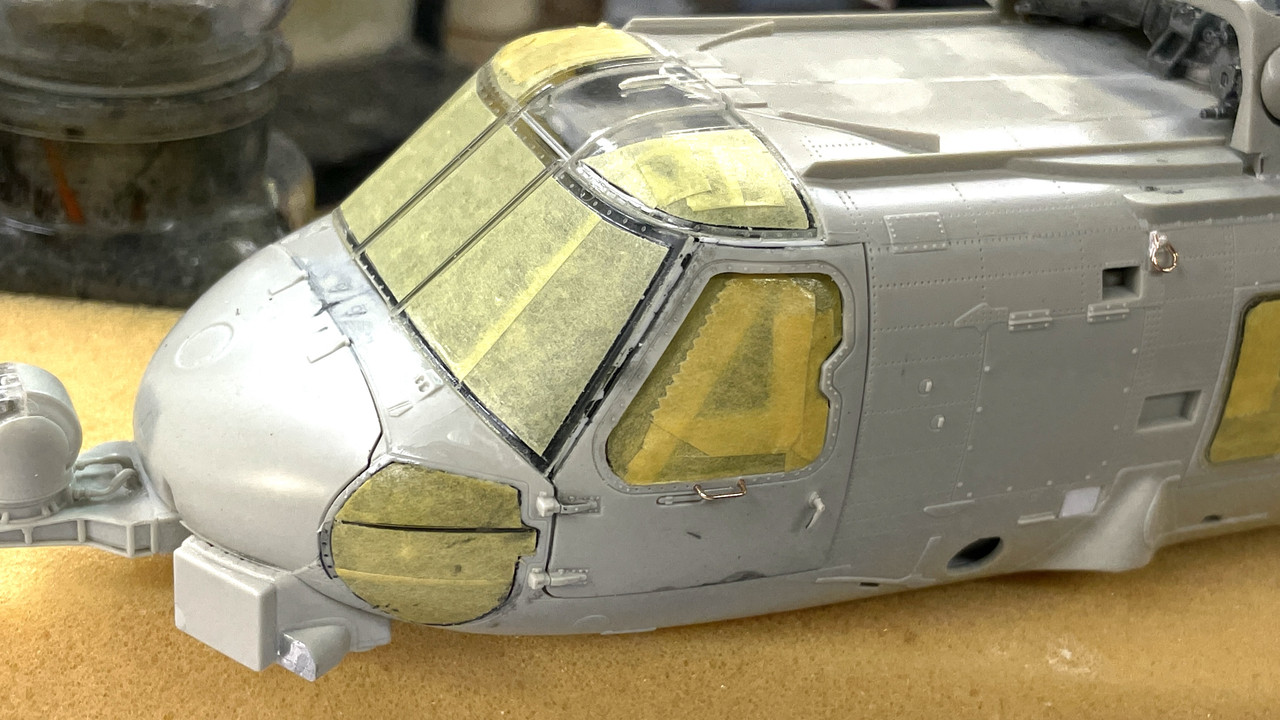
It was time to install the nose cone and the lower corner windows. After putting on the nose cone, I had to paint the edges and touch up the interior before the glazing could go on.
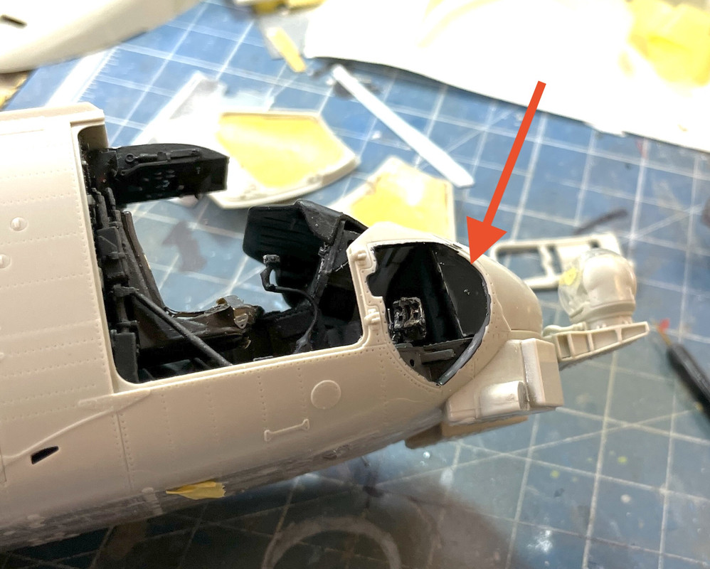
I masked these windows off the model and then glued them in place, again with canopy cement. Again I sealed the edges with clear. I’m re-thinking installing the main glass to avoid having to mask the delicate interior.
It’s too bad that you can no longer see any of the avionics which I so painstakingly painted…
5 Likes
Looking great. The details are really making it pop.
I always install the canopy/windscreen first and then mask off the clear areas before painting, just like you did on the side windows. I find it way easier than covering up all of the interior.
Thanks Gino! I did do just that. I did all the masking off the craft and then glued it in place. I did NOT use canopy cement. It’s not secure enough. I DID use solvent cement and think I was careful enough to not wick it onto the clear portions. The Eduard decal set almost worked perfectly for these windows. I say almost because the Seahwak version does have some slight variations even on the front windscreen starting with the overhead control panel that is a painted portion of the glazing and has a curved portion on the left top that gets left unmasked. I’m adept at using a #11 to trim windshield masks even without them being pre-cut. None of the side windows masks worked at all.
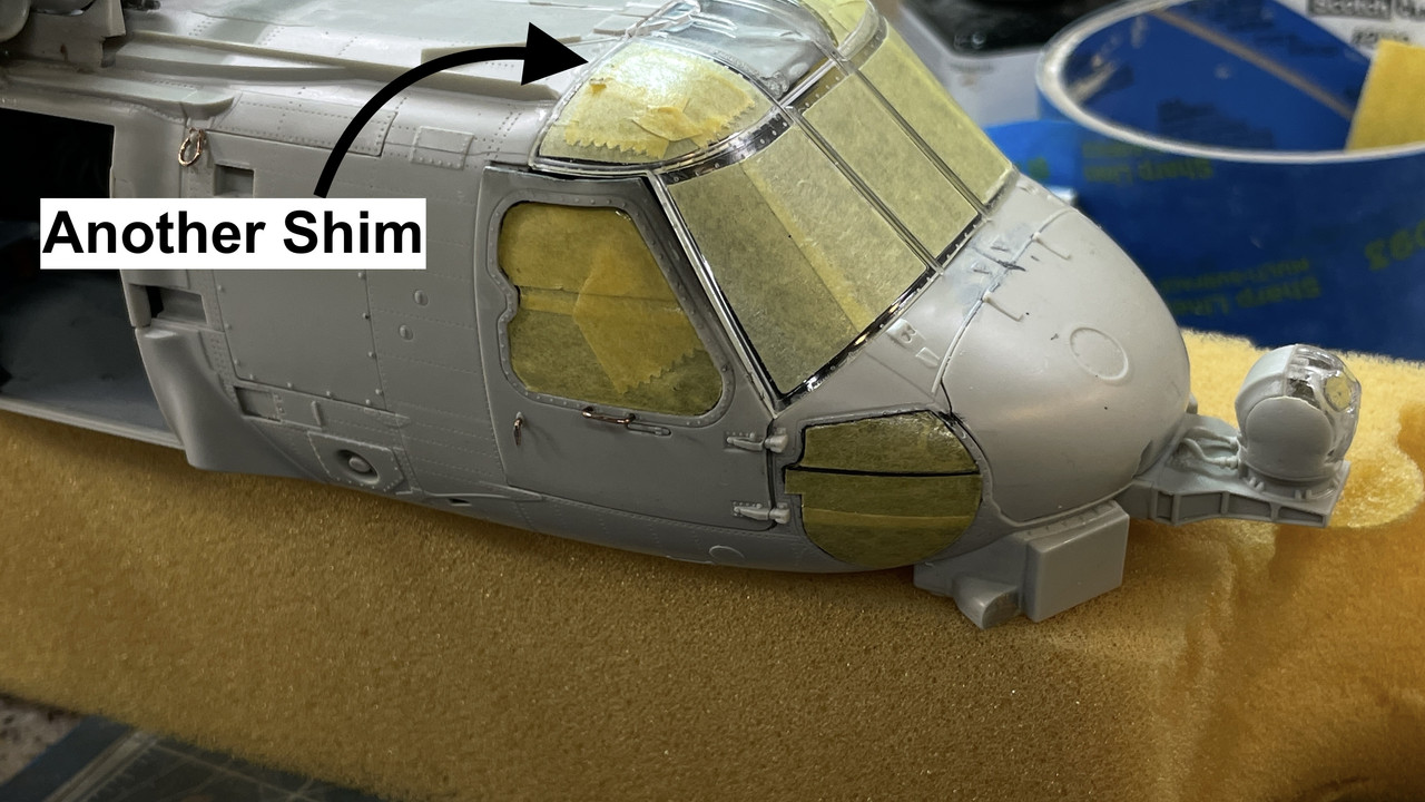
That 1/32" cap on the roof keeps rearing its ugly head. In this instance it made an objectionable gap on the left side door, both on top and at the windshield joint. The windshield ended that gap’s thickness too soon and didn’t reach the door.
I again used shaped styrene to fill the gaps. There was also another gap at the right-top-rear edge of the windshield, also filled neatly with styrene. Filling with styrene reduces (not necessarily elimates) using paste fillers that often need multiple coats to fill a stubborn gap.
![]()
Before snapping the door in place (no glue needed), I painted the inside of the shim with interior black using a brush with a long handle from the opposite side of the cockpit. That’s in case the rivet counters peer through the open door and see white styrene on the other side. I know, I know AMS!
With the door in place the gaps are now closed and the door fits tight enough to not need internal masking.
The right side fit was too tight and I had to trim the inner door frame so it would close enough to seal the paint out. The other shim is pointed out here. I had to use some canopy cement on the door’s upper edge to keep it shut before painting. As I said, it’s not that strong and the door is removable. This door will be open.
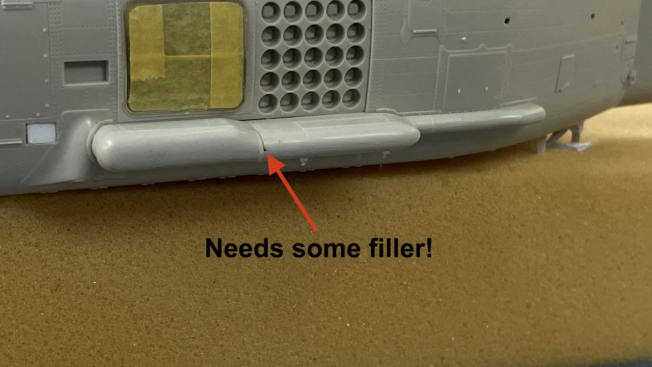
I added the left side weapons sponson. it too had four of those tiny sway braces. Little spot needing some filler.
We’re not making out annual trip back East for New Years. Too many unknowns with the pandemic. I’m telling y’all this to say, building will not be interrupted.
5 Likes
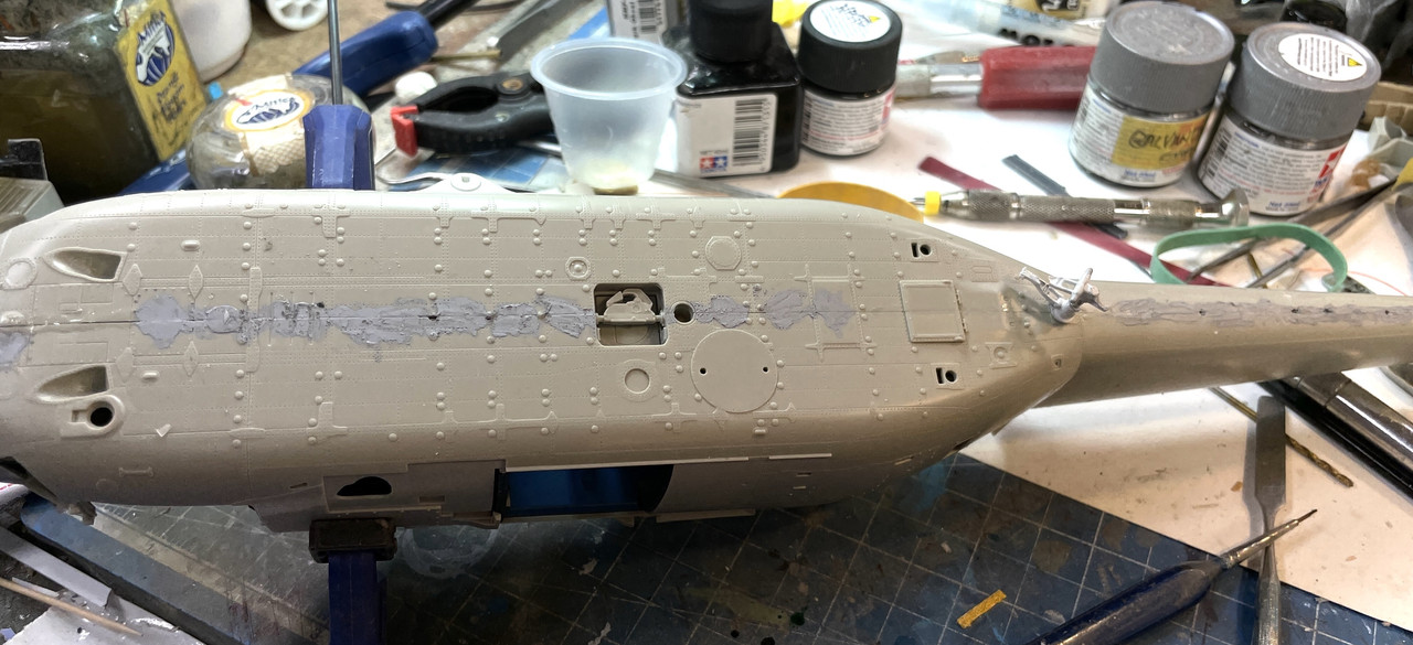
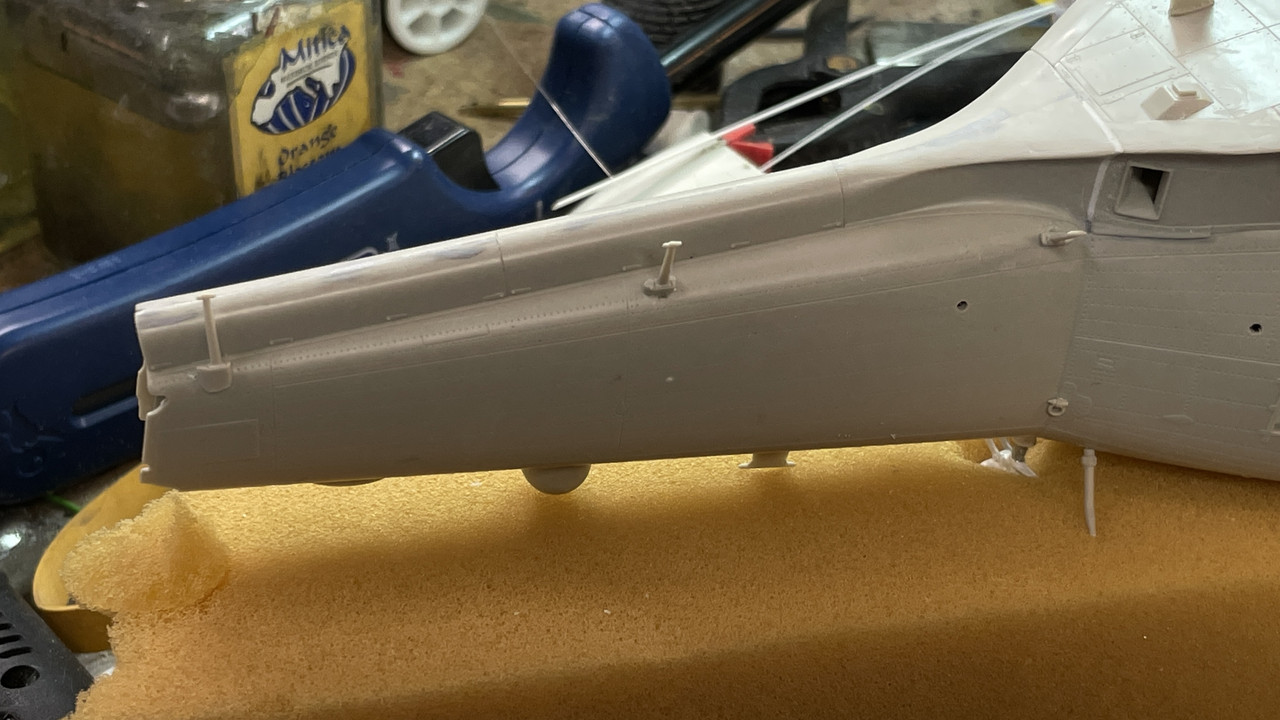
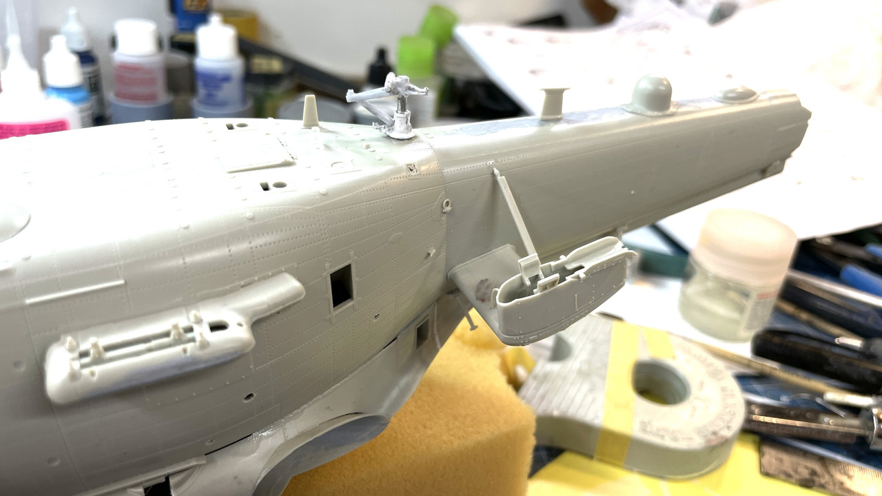
More fuselage work…
Before I forget, let me make a proclamation. DO NOT PUT ON ALL THE LITTLE ANTENNA AND OTHER THINGYS THAT STICK OUT FROM THE FUSELAGE (technical term) WHEN THEY TELL YOU TO IN THE INSTRUCTIONS. PUT THEM ON AS CLOSE TO PAINTING AS POSSIBLE. Otherwise you will break them! And repairing them is neither fun nor optimal. I’m really annoyed that I didn’t follow this advice and have been repairing things that stick out continously as I handle the model to do other important things.
I built and installed the mount for (I am assuming) is the 1198 Penguin Air to Ground Missile. This one had a signal line in styrene and a sway brace that flush mounts to the fusselage.
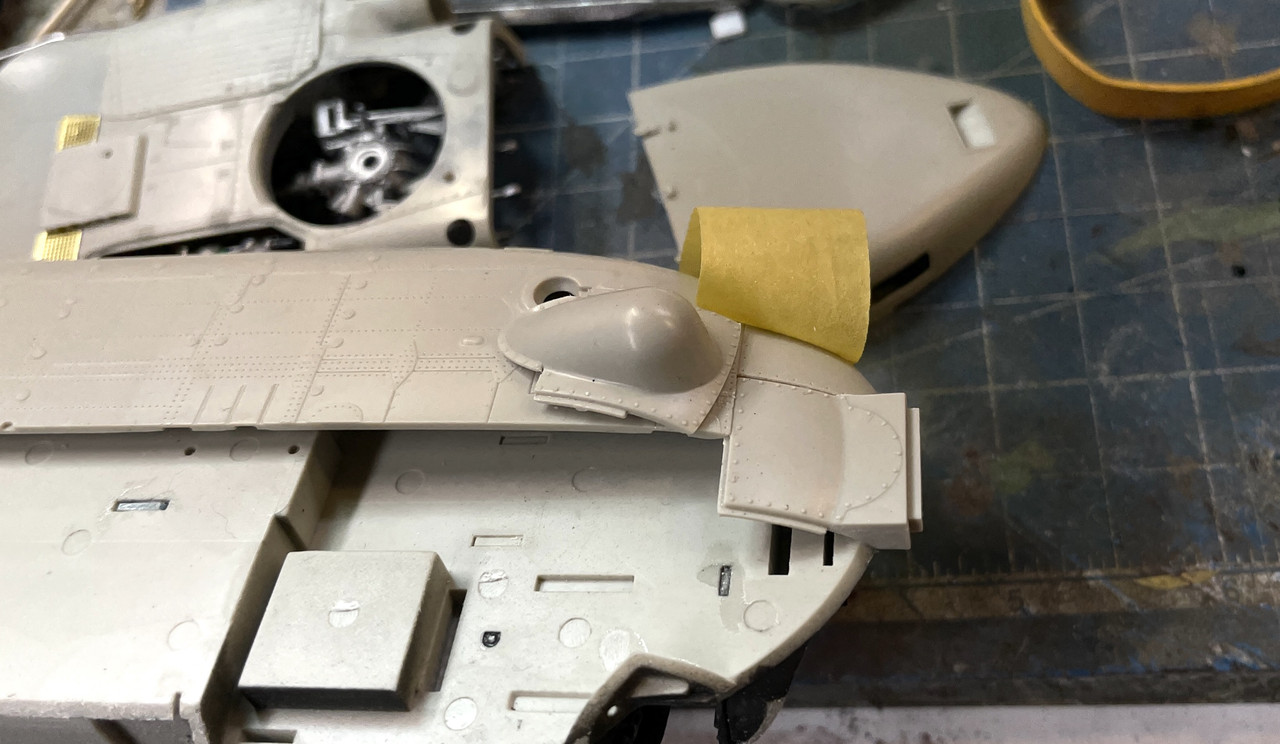
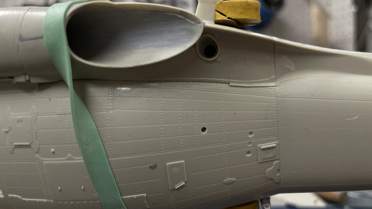
I’m preparing the model for painting. That requires mixing up the instructions. In my case it meant putting on the hydraulics fairing that wasn’t called out unti near the very end. It will also include the bottom radome that goes on tomorrow.
The fairing fit poorly, again due to that fuselage gap. As I mentioned yesterday, this gap keeps rearing its ugly head forcing parts to no longer fit by the amount of the gaps dimension. I don’t know what I’m going to do with this mess. I may build out and smooth the flank to erase this discrepency. Might as well since I’ve been doing it all along.
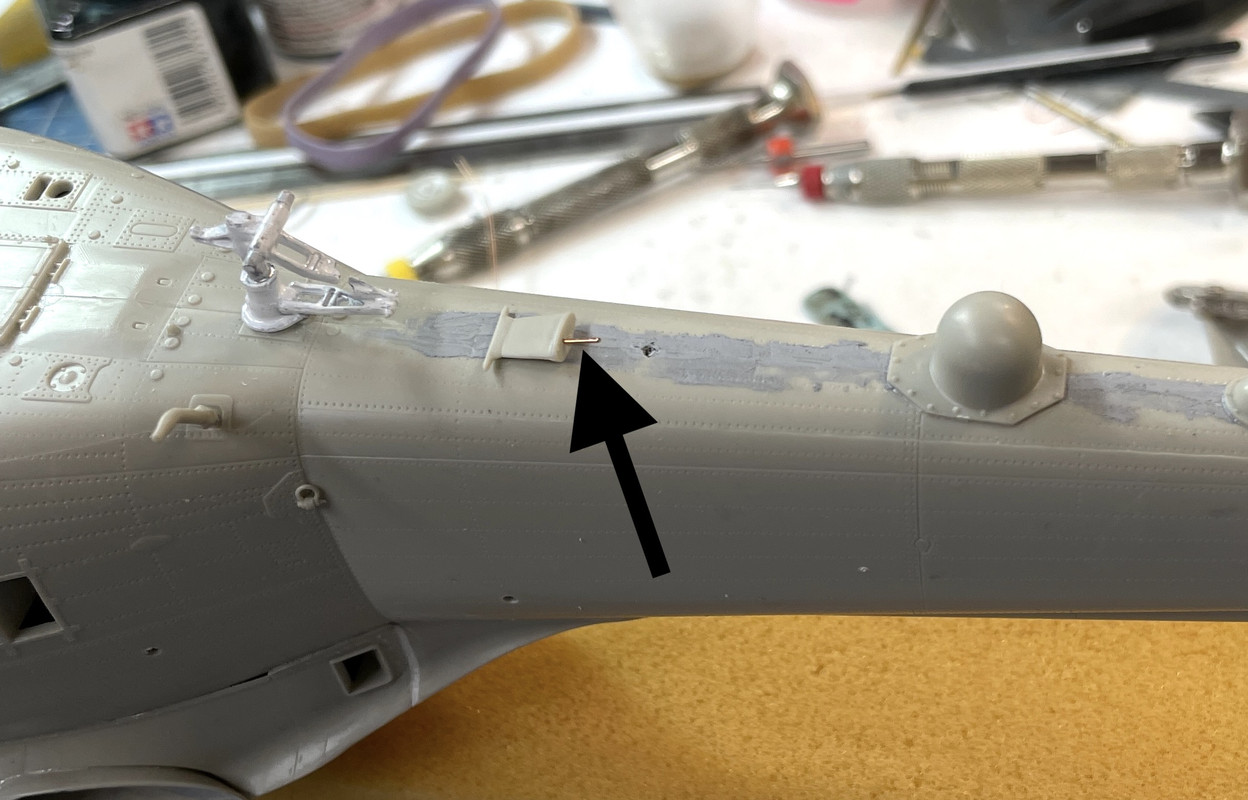
In my handling I doinked the rear antenna mast. These protrusions are the reason I made the proclamation at the start of this post. I didn’t even know that I broke it until I found it as you see it here.

I was just thick enough that I could actually drill and pin it. Not a pefect solution! Further smooting will help a bit.
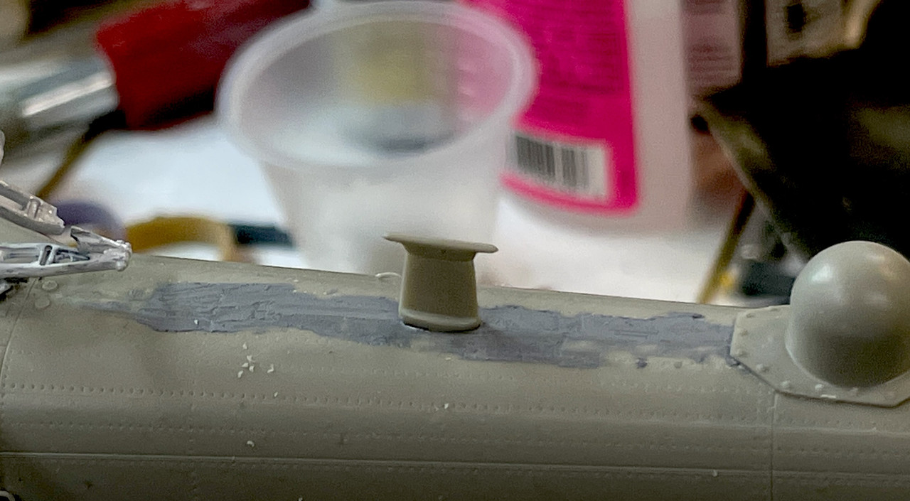
To prevent more of this, I chose to fabricate the remaining two of this array out of metal. They are standoffs for a wire antenna that I’m going to assume is a low frequency communications link, but Gino will correct me.
I formed the phos-bronze and cut some PE fret for the bases. I will further finish them by bulking out the airfoil shape of the mast with some CA or Bondic. I solder these embedded into a ceramic soldering pad that is fantastic for soldering small assemblies. I will do this again when I fabricate the metal tripod that’s going to support the rear-view mirrors. I’m going to replace the styrene struts without giving it a second thought.
Here are the two supports ready for further finishing.
The rear EMS pods went on port and strbd without problem.
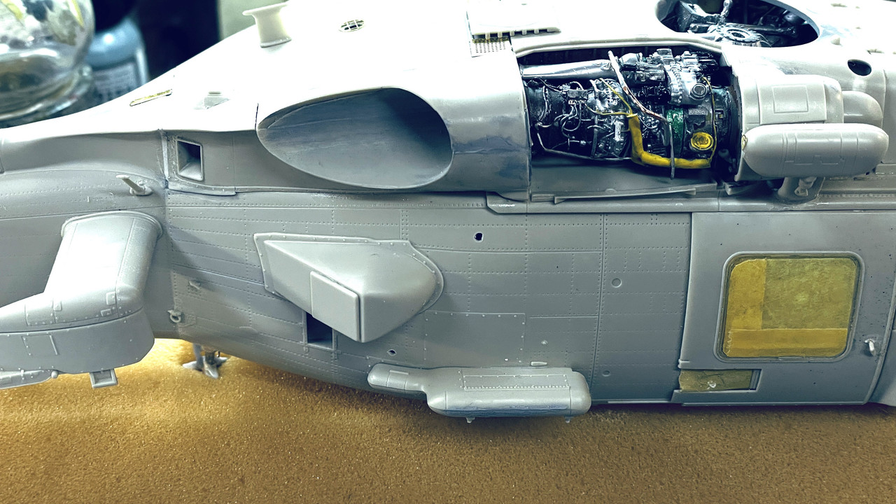
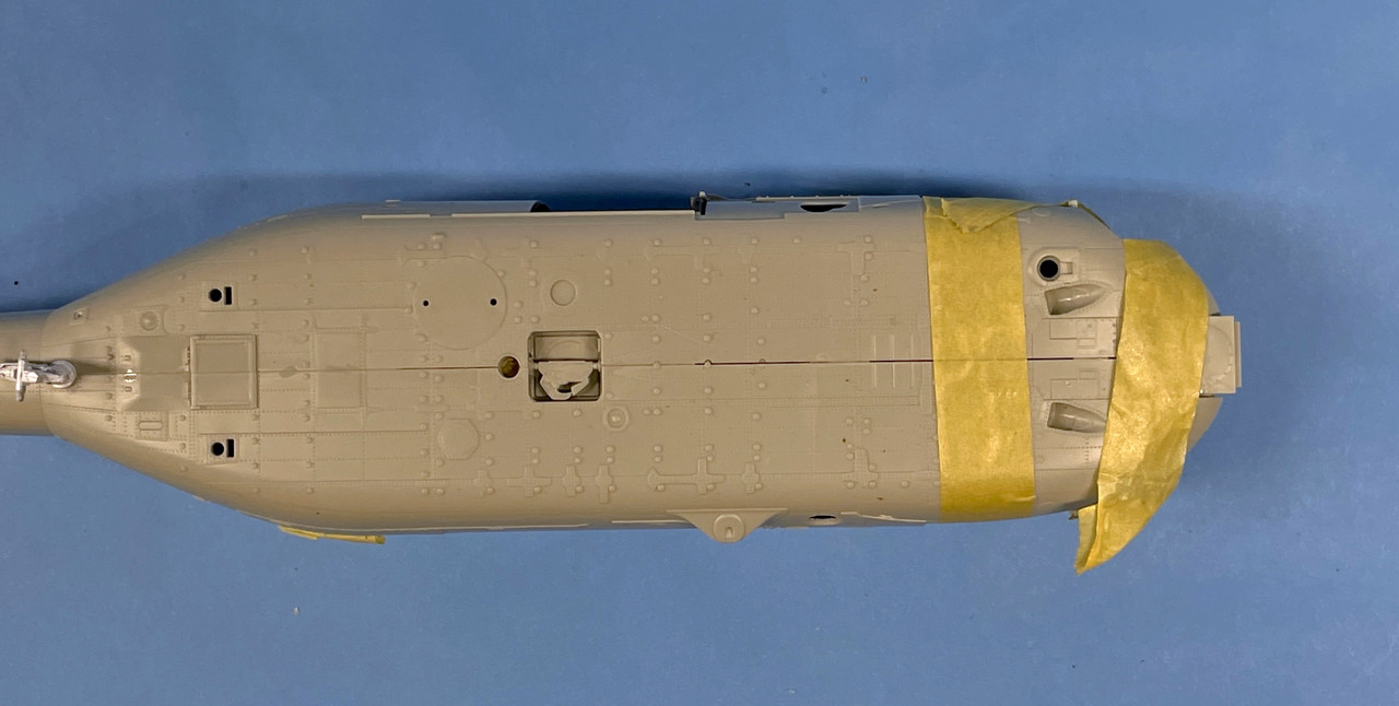
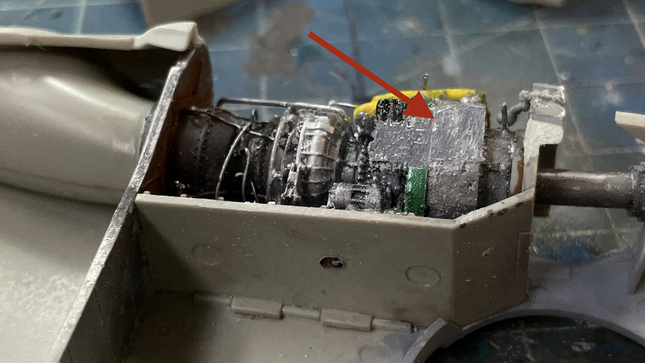
I also forgot to color the floor of the engine compartment so protected the engine and airbrushed some dark iron into the space. I also did this on the inside of the engine cover which will be displayed open. I first shot this with the Tamiay silver laquer. Paint was scrtched off when I was fitting it.
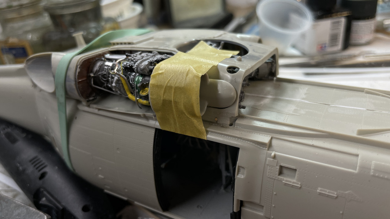
For initial engine protection during painting, I covered it with some wet Bounty towel.
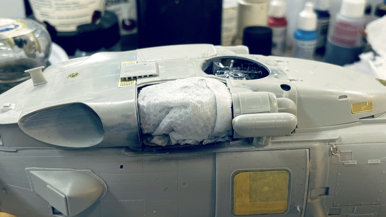
And then stuck the engine cover on as best I could.
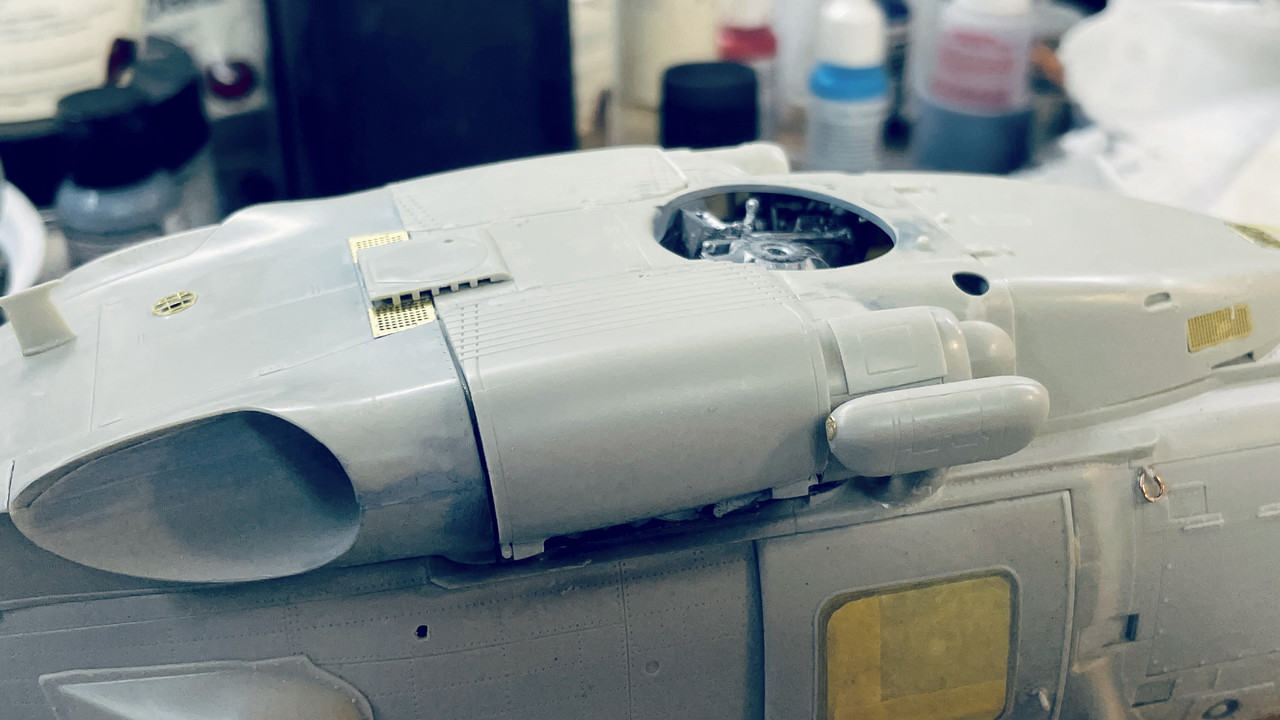
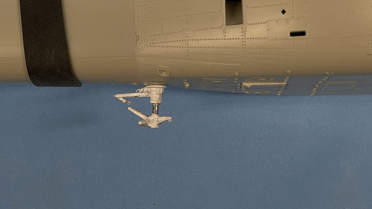
We’re getting close to painting time. I have to install the main landing gear and then work on the tail boom including the ResKit swing joint and tail rotor, so there will be some resin building fun. I have to decide whether to paint the exhaust ducting before and masking it and the shoot the gray, or after and and mask the gray. Any thoughts? I’m also thinking about how to actually hinge the copilot’s door.
3 Likes
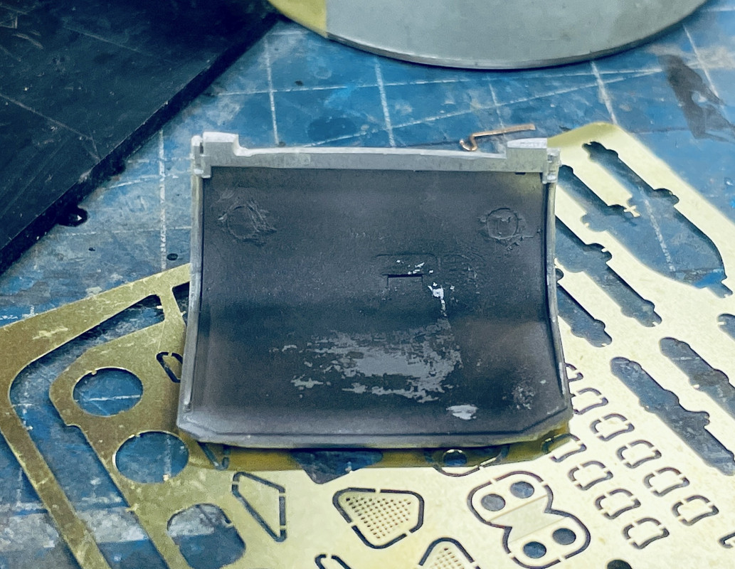
Looking great. The antenna along the fuselage is a low frequency one. As for the inside of the engine compartment access cover, it is actually zinc chromate yellow, has a flat plate for a floor and black anti-slip tape as it is used as a work platform, as on the UH-60s below.
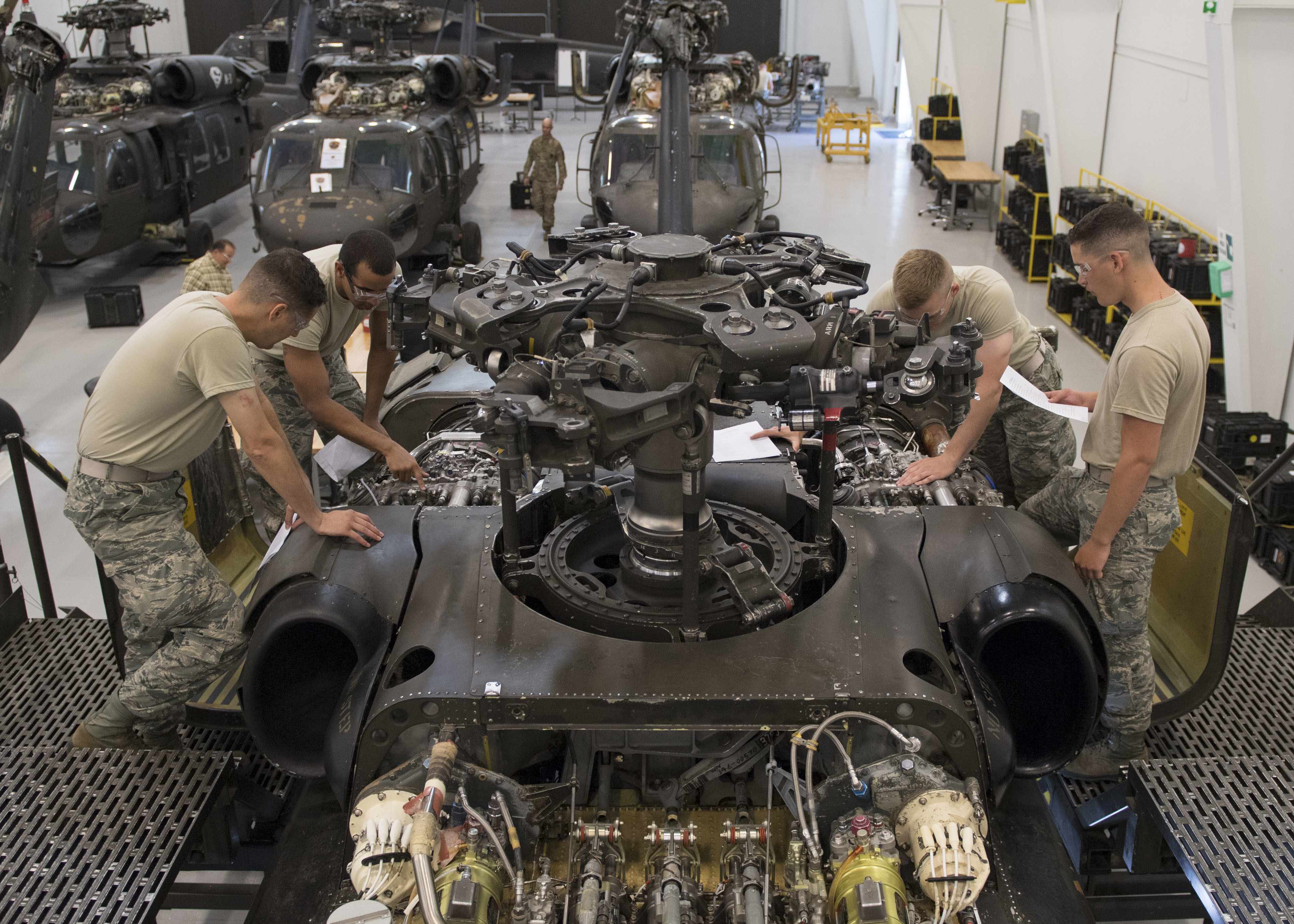
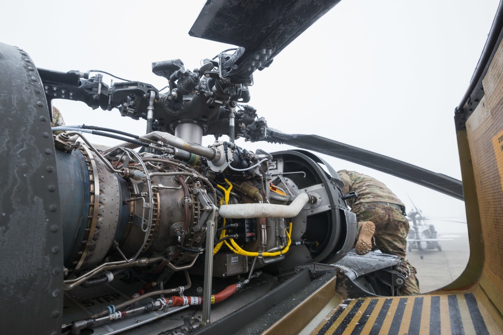
You can see the flat floor plate well here.

1 Like
Great! I’m make that change. BTW: it’s not a Penguin missile rack. It the MAD Bird (Magnetic Anomaly Detector) towed array rack. Did some more research.