BLOG: Kitty Hawk 1/35 SH-60B Seahawk

Hope everyone had a decent and safe New Years. We stayed put and had a nice FaceTime with our friends back East. We’re all getting older and several folks from our group were having health issues.

Put the metallic antenna loops onto the Fuze after making a 3rd one. I was trying to add some bulk with various kinds of media including epoxy putty and Bondic. Putty didn’t stick. Bondic did sort of. When attempting to shape it with the Dremel I thinned the phos-bronze too much and it bent in half. Ergo, making another.

I put them onto the fuze with gel CA with a bit of medium CA to smooth the edges a bit. These should be more rugged than the frail styrene ones I was replacing.

The movable part of the tail boom gets glued together now, but before you do you have to captivate a actuating cylinder in two slots on either side. I didn’t like the depth of the plastic lugs so I added some 1/32" phos-bronze.

I got started on the ResKit tail boom hinge replacment. It’s a pretty complex little project including faux pulleys with wire simulating the cables that control the tail pitch. You have to remove material on both the fixed and movable parts to create proper space for the more detailed resin parts. And here are the results. I used a combination of #11 blade, micro-razor saw and an Xacto #11-sized saw to remove the plastic.

The hinge area had to be surgically removed to give space for the more detailed hinges on the resin parts.

Here’s the fixed boom with it surgery completed.

Lastly, here’s the first resin part that I’m preparing. You have to open up some slots in the part as well as cut it out of the sprue block. The resin is tough, but not that tough and you can screw it up pretty good if you’re not careful. You can see the highly detailed hinge parts that will fit into the newly cut holes.

3 Likes

Spent most of a long work session fixing a mess! You see I misread the instructions on “what to remove” on the tail booms. The plans showed the colored area and I read that as it needed to be removed… which I did yesterday. When I trimmed out the resin hinge bulkheads and fit them, this is what I saw.

That humongus gap was the material I erroneously cut away. You weren’t supposed to “remove” that colored area, you were supposed to “thin” it by .3mm from the inside. I neglected to see the decimel point and my ADD brain jumped to the wrong conclusion. The resin pieces were still supposed to sit between the fuselage styrene. They were just a little thicker, so the styrene needed to be re-shaped.

This meant I had to add back the missing material and dress it so it wouldn’t be noticeable to the novice viewer. Show judges would probably pick it up. I used some styrene strip held with both solvent cement and CA. I replaced rivet holes in the new parts.

I then shaved the new material on the movable boom so the piece would sit between the packing. On the fixed portion I have the hinge butting up against the fuselage.

With the both sides fit to their remade ends I was able to actually start building the hinge assembly. As usual ResKit is asking you to assemble and fabricate stuff that just about at the edge of my skill set. Lots of butt joints held by CA. The pulleys are almost microscopic and they expect you to thread some .2mm wire around them to simulate control cabling. I’m thinking about it, but may not do it. I actually hinged the parts with 0.022" wire and they work, but…and it’s a big but… the next parts you add prevent the hinge from working.

I glued the part to the movable boom and that’s where I had to stop. The folded boom would block painting of the fuselage and the closed side of the boom. I will have to glue it all in after the painting.

There were more gaps that need filling. I used a combination of a thin styrene and Bondic. I traced the shape of the open onto a piece of paper and cut the piece. It need more adjusting and then further filling.

Here is the gap filled.

Last thing up today was the tail strike bumper. This little assembly was one of those royal pains in the butt. If you’ve had the fun of watching “Rocco Sciavoni” on PBS streaming, you’d know that this was probably a “9th level pain in the ass.” He ranks them with the 10th level being a murder. This little job took 15 minutes or more.

You have to captivate the movable strut in the two holes and then glue it together. The triangualar shape made gripping difficult and the part kept rotating and coming out of the holes. I tried all sorts of things including taping one half to the bench so it wouldn’t be moving around. I finally got to a big sigh.

Once I got it together, putting it on the plane was not a problem. It could have been engineered differently since the part is not actually movable in the final install. It could have been slipped into a slot and glued.

As much as I’m champing at the bit to get painting this job, all these bits and pieces must be installed properly. And, BTW: That pointy antenna sticking out of the bottom broke off AGAIN! As I said, IGNORE THE INSTRUCTIONS AND GLUE ALL THE TINY ANTENNAS ON AT THE LAST POSSIBLE MOMENT BEFORE PAINTING. Otherwise, you be re-gluing them, and fixing them for the rest of the build. There are so many that it’s hard to grab the beast to do any heavy lifting (like adding filler pieces at the tail to fix big mistakes).

3 Likes

Looks like a good recovery on the tail fold hinge parts. The RezKit replacement pieces really add to this part of the build.

Yes! The ResKit parts do make a difference as long as I don’t break anything.

As you can see I screw up with regularity, but I also have great recovery skills and lots and lots of persistence. I had a short session and kept working on the tail boom and the main landing gear.

The tail boom has a small vertical stabilzer that went on nicely. Needed a little filing here and there to get a close fit.

I then needed to back up and build the main landing gear. The instructions on its assembly are a bit sparse. The main gear housing (minus the strut) consists of a 3-piece sandwich. I built the first one after figuring that the two pieces I removed from the sprue didn’t quite make the whole assembly. Then I went to cut the parts for the other side and only found two of the three on the sprue. I didn’t remember cutting off one of those pieces, and after a thorough search of the work bench area and parts racks, was unable to find it. It was quite desparate becasuse this was not an easy part to scratch-build. I did a complete search of the immediate floor around the workspace, but nada. Then I spotted a beige piece of plastic across the room under my 3D printing bench. And it was the missing piece! I don’t know how this happened, but I was very happy that I didn’t need to fabricate a new one. And with Kitty Hawk out of business, I don’t know of any way to get a new part from them.

The strut is captured by fingers in the housing and, if the shock strut actually moved, could articulate. But… since the strut is solid the gear is fixed. I also glued the wheels together in preparation for painting. BTW: a large part of the filled underbody in the front will be covered by the large, round radome.

And we had our first snow of the season here in Da Ville. Winter has finally arrived.

3 Likes

Its coming together nicely. Almost there.

A reader in the other forum gave me a link to the Mil Spec Color book that showed this kind of bird. I have the cross-match for the three kinds of gray some of these are painted with dark Ghost gray on vertically facing surfaces, and light gray on the bottom with the medium in between.

I’ve been studying a lot of pictues and some look to be the medium gray throughout. Some of the images show the vast variations in weathering that can be applied from sparkling clean to worn in various spots especially the underbelly.

This one is pristine! And appears to be monochromatic.

Here’s some underbelly soiling that could be added. It also shows the lighter bottom color and it looks like I’ll have to add that. Good view of the missile detection sensor on the EMS at the front corner. And here I thought it was another search light… The cargo hook in the belly looks like it’s painted light blue.

And another bird… Again, very clean… a little soiling on the tail boom. Also, panel lines are very tight and not very noticeable. Amazing extension on the tail wheel shock strut.

Here’sa close up showing just how clean these things can be. What is that red panel with the handle on it? Notice the Maverick missile loadout.

Another bottom shot. This one again shows the soiling esepcially in the low pressure area behind the radome. This one looks like the bottom is NOT painted in the lighter color.

2 Likes

Keep in mind that Naval aircraft get bathed a lot due to the salt air environment they live in. I have seen 2 or 3 SH-70’s with a most definite 3-Gray livery. They actually look rather nice next to my son’s rather drab UH-70L. Keep up the great work!

Also depends on how long ago the bird was in the depot for repaint, the top color fades “quickly” to get that monotone look on the top and bottom.

It is, look at the tail. You can see transition lines , the front is just heavily stained and sorta masks it.

I’m late in your post, but reading it now I have to tell you that you’re doing an absolute masterpiece. Your attention to details are amazing.

I’ll follow your new posts from now.

Congratulations!

Thank you all. I have a few other full builds on Fine Scale Modeling’s forum

  • 1:32 Tamiya Corsair, Meng
  • 1:35 M2A3 Bradley BUSK III
  • 1:35 Ryefield Sherman M2A4 76W HVSS with Full Interior
  • 1:24 Airfix Hawker Typhoon
  • 1:32 Trumpeter F105G Wild Weasel
  • 1:24 AMT Ford Fairlane GTA (my college car)
  • 1:350 Trumpeter Essex updated to late WW2
  • 1:32 Trumpeter ABM Avenger
  • 1:48 Monogram B-17G customized to “Yankee Lady”
  • 1:350 USS Missouri full-museum build. (not a full build)

Here’s the listing on FSM: FineScale Modeler - Essential magazine for scale model builders, model kit reviews, how-to scale modeling, and scale modeling products

That should take you the rest of 2022 to read. Meanwhile, I’ll keep going on the Seahawk.

2 Likes

Here are good diagrams that show the 3-tone color scheme.


1 Like

Great diagram and good info of the updated models.

Today’s post combines yesterday and today’s work. Got the tail rotor built and wrestled the horizontal tail plane into submission.

The ResKit tail rotor has great detail, but in my case, the lifting rods (that control the pitch horn) just seemed way too short so I substituted them with 0.022" wire. Drilling the small rod ends was painstaking, but went ahead without difficulty.

Here are the four blades with the three parts attached: Blades, hubs and angled horns.

The arrow denotes on of the tiny counterbalance arms that broke off during cleaning. Another broke during assembly so two are not metal. Nothing attaches to these protrusions.

The four lift rods go between the spide and the horns. The arrow points to the kit part that just is way too short. I doubled checked what I was doing and couldn’t find a mistake.

The instructions called out exchanging the kit supplied prop shaft with another that was significantly shorter. Unfortunately (for me) I had already fully assembled the tail boom and that required this part to already be installed.

The solution was simply to drill the resin hub deeper to accept the kit’s pin.

Here’s the rotor in place without glue.

Next was finishing the boom with the horizontal wing. I glued it up according to the instructions. The actual gluing points between the side pieces and the center were ridiculously small and fragile.

After it cured for about an hour I tried to snap it into place with the two small pins protruding from the center piece that engaged into two holes in the tail boom mount. It was quite flimsy, and when I put it into the folded position the wing was completely in the way. How the heck did this thing fold?

As I studied the tail plane I realized that those delicated attachment points were actually hinges. The darn thing folds! This was not called out at all in the instructions, nor did I study the folded tail intensely enough to pick this out. So broke the previous delicated joints and realized their surface area could not support the tail pieces in the upright folded position. Instead I faked it and made some phos-bronze wire supports. They’re not scale nor prototypical, but they’ll support the tail pieces in the display position. While the main rotor is folded hydraulically, all the tail boom folding appears to be manual.

That finished yesterday’s work. Today I ‘hinged’ the opposite side and did some more work on the center section. I drilled it out 0.022" and then opened to 1/32" and used wire to make a much stronger assembly.

And here’s the end result with the tail planes in their folded position (unglued) that will allow the boom to fold next to the fuselage as it should.

Now y’all are up to date.

5 Likes

One of my readers, Svt40 on the FSM Forum, made a valid input and of course I never ignore valid input. The first thing I did today was add the wiring that goes from the pitch hub into the center fitting on the tail rotor. You can clearly see this wire in this image. This wire’s hole would have been MUCH easier to drill had I realized I needed it BEFORE building the whole deal, but I persisted and got the holes drilled. I am NOT installing that finer loop wire that goes from the spider. The wire in question is the fatter one.

It’s interesting to note that the rotor has no actual hinging for the pitch control. There are two crossed carbon fiber beams that go from the tip of one blade all the way across the center to the tip of the opposite blade. The fiberglass blade sleeves slips over these beams. The beams act as torsion bars and will twist when pitch motion is introduced into the. The blades leading edge are titanium and there is an applied rubber de-ice boot on the leading edge also.

Svt40 also pointed out several other small details that I’m going to add. One is the ehad of the rotor indexer. The indexer positions the blades so they don’t get damaged when the boom is folded. I put the motor shaft in, but his drawing also calls out for some head detail. I’d love to get a picture of it. My search today came up empty.

The other details are the removalable struts that secure the tail planes in their folded position and secure the boom itself. I will make these also. And I need to get some “remove before flight” tags.

This image shows the struts in position keeping the tail plane in the folded position. The picture also nicely shows the color line for the white/light gray bottom.

The strut goes from the movable hinge to the fixed hinge.

I put on the static probes, but they’re really flimsy and I constantly was bending and unbending them. They needed to be on becasue it would be awful to try and install them on a painted model. In this image you can see the index motor shaft. The boom is almost done.

Here’s a fold test to prove that YOU DO NEED TO FOLD THE TAIL PLANES FOR THIS THING TO WORK. The instructions missed this entirely was a big and almost fatal omission.

I kept breaking that rear antenna support. I fixed it at least three times and each time it was getting worse. I bit the bullet and made one out of soldered wire. Not exactly scale due to the round versus airfoil cross-section, but it ain’t gonna break.

We’re really closing in to the day when I break out the masking tape and airbrush and start painting this model. All in all, it’s one of the most challenging and complex plastic aircraft kits I’ve ever built. I knew it would be a challenge, but the addition of the ResKits really upped the ante. Some of the challenges were my own doing in fixing my mistakes. Others were just in the nature of the beast.

Any ideas for a carrier deck base for this model? I’m sure there are 1:32 bases. Would they work for 1:35.

3 Likes

It is coming along great. Good additions of the prop rods.

For the deck, there is this…

I have one and it looks really nice.

1 Like

I love the work and how you solve all the issues. The folded wings looks superb.

For the base, try to make your own base. There are some products in the market to make surfaces. I’m going to try my first tarmac base for the Strike Eagle I’m working on.

If you want to go that route, Reedoak makes the 5-point modern USN deck pad eyes, aircraft tie downs, and chains to secure them properly.

1 Like

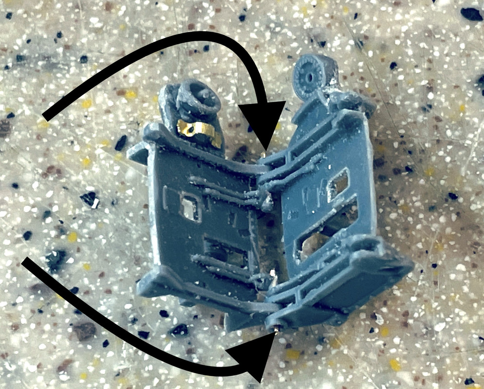
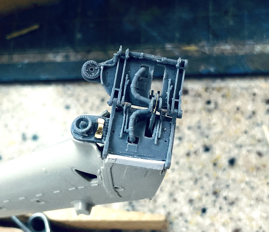
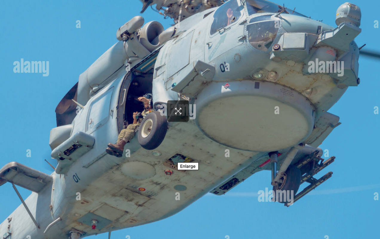
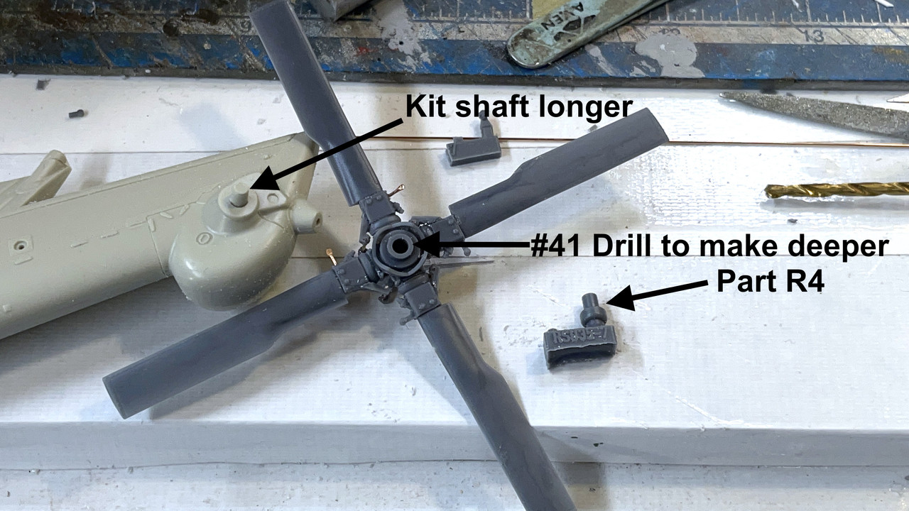
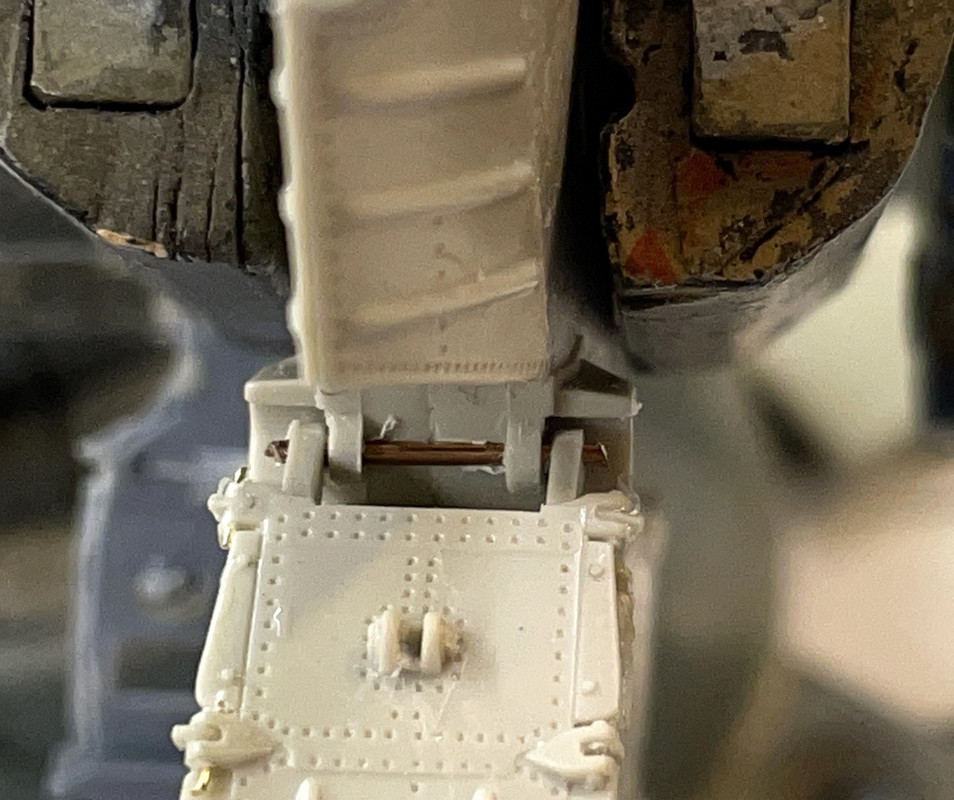
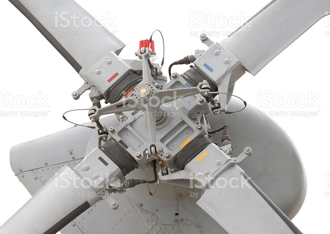
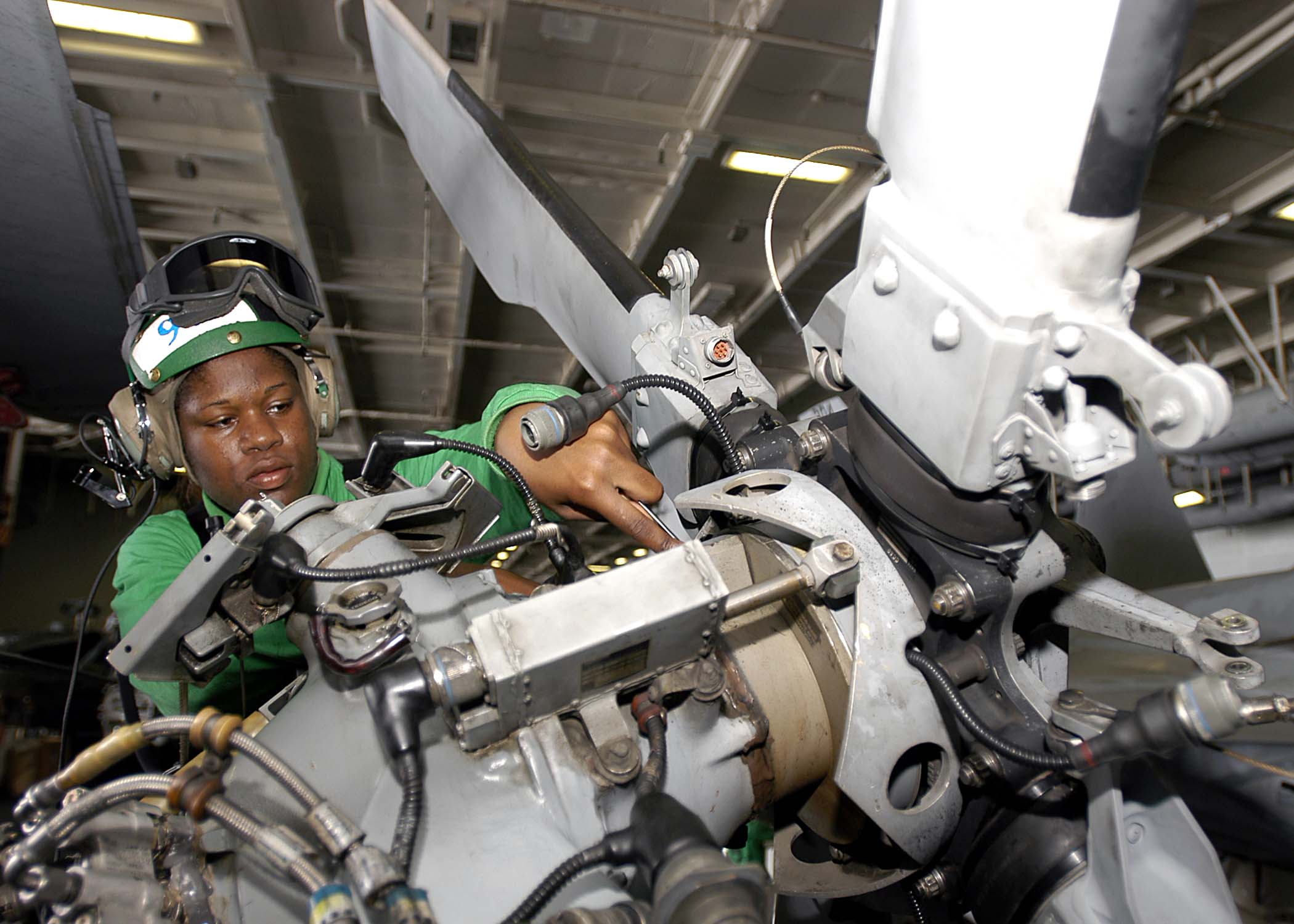
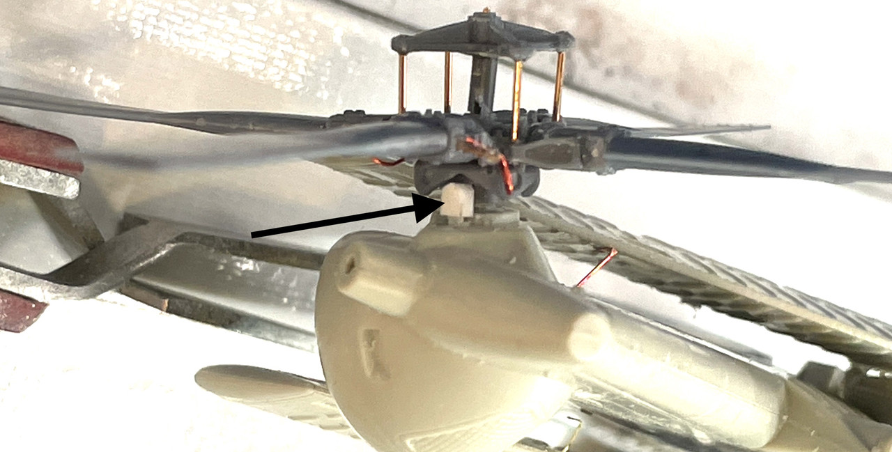
Svt40 on my thread in the FSM Forum posted this great image showing the inner details behind the tail rotor housing and details of the index motor head.

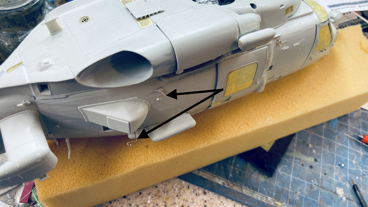
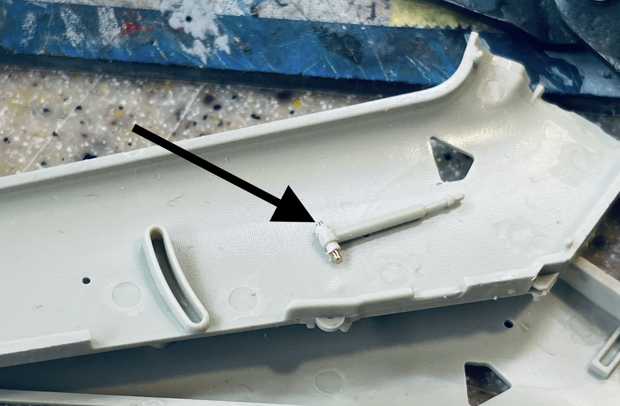
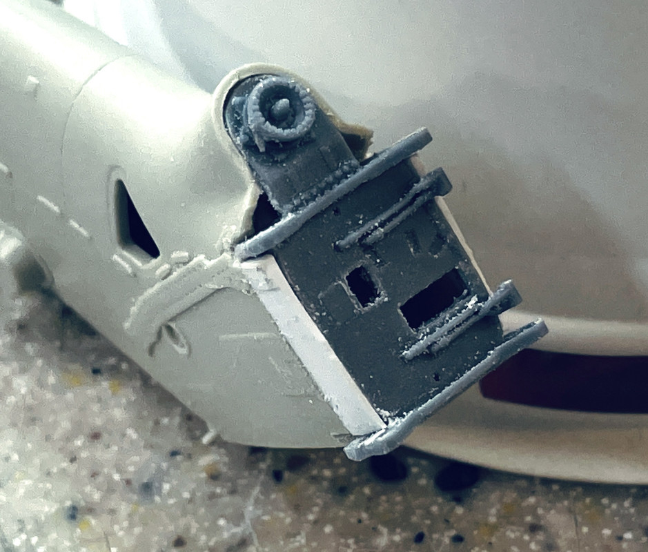
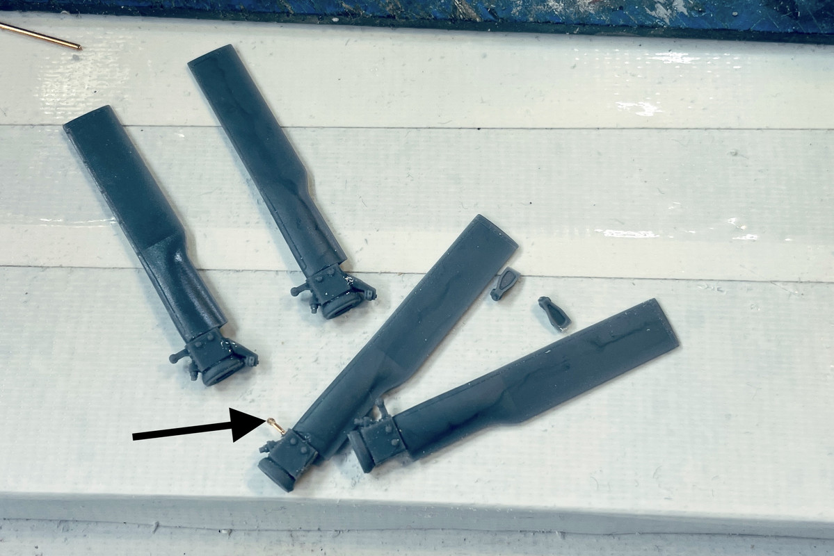
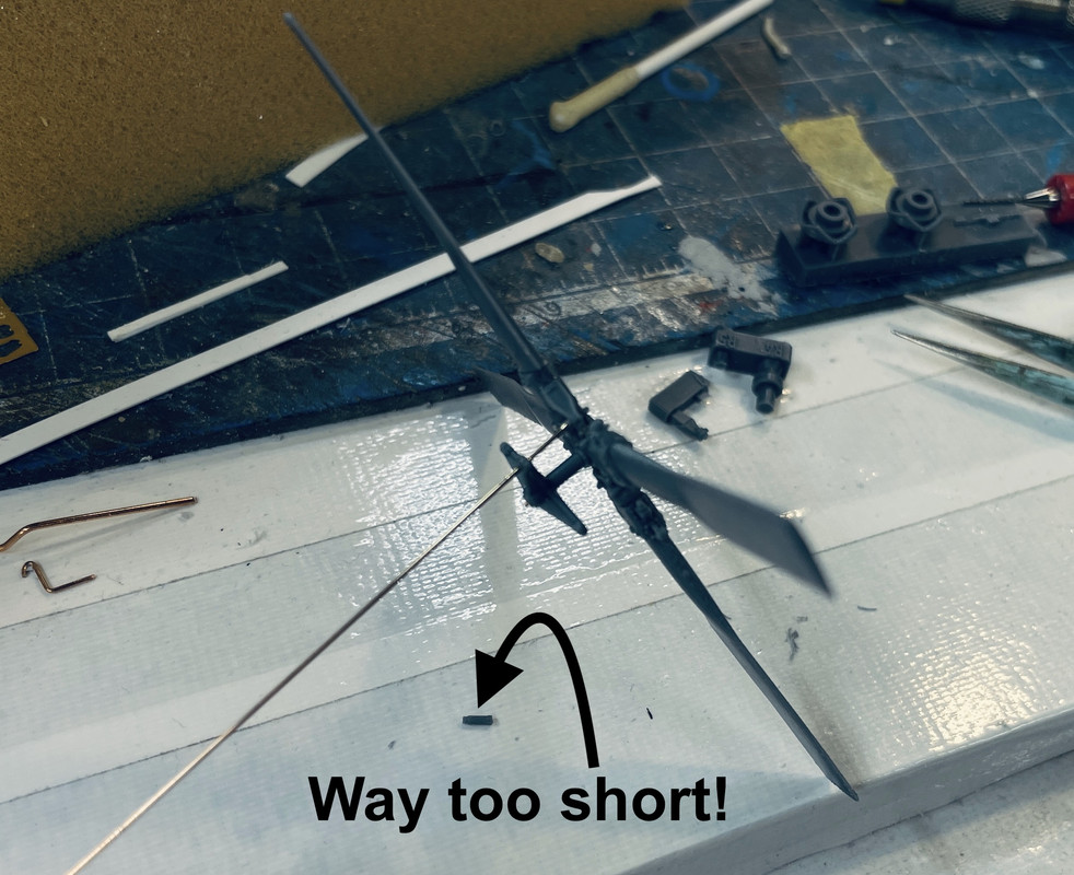
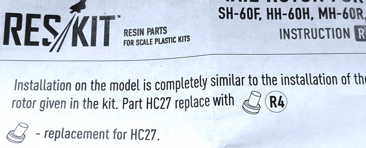
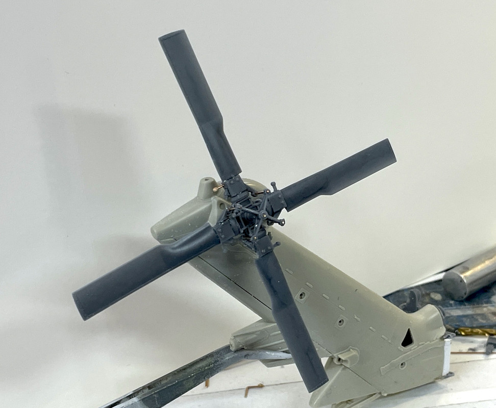
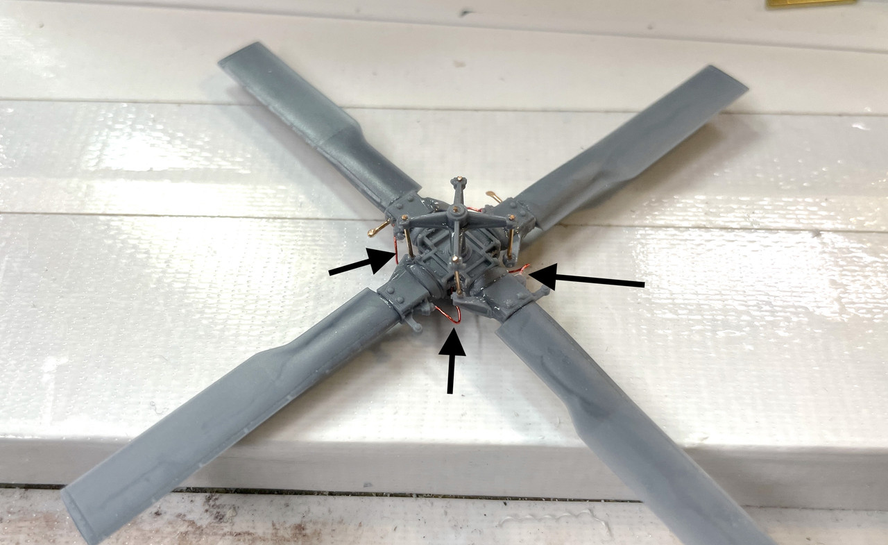
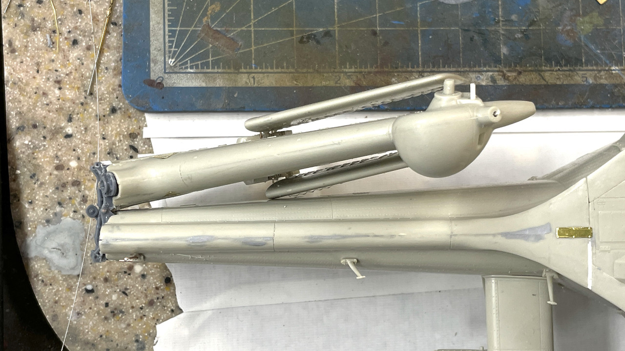
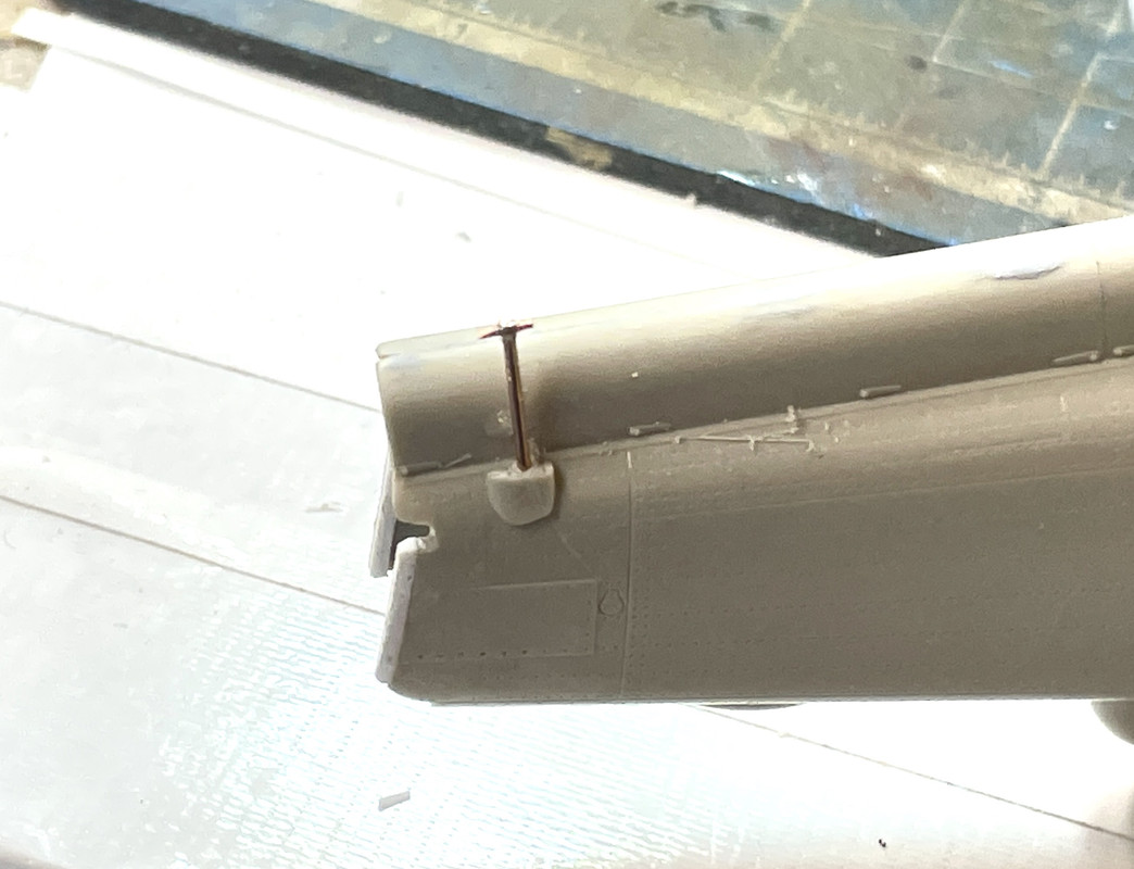
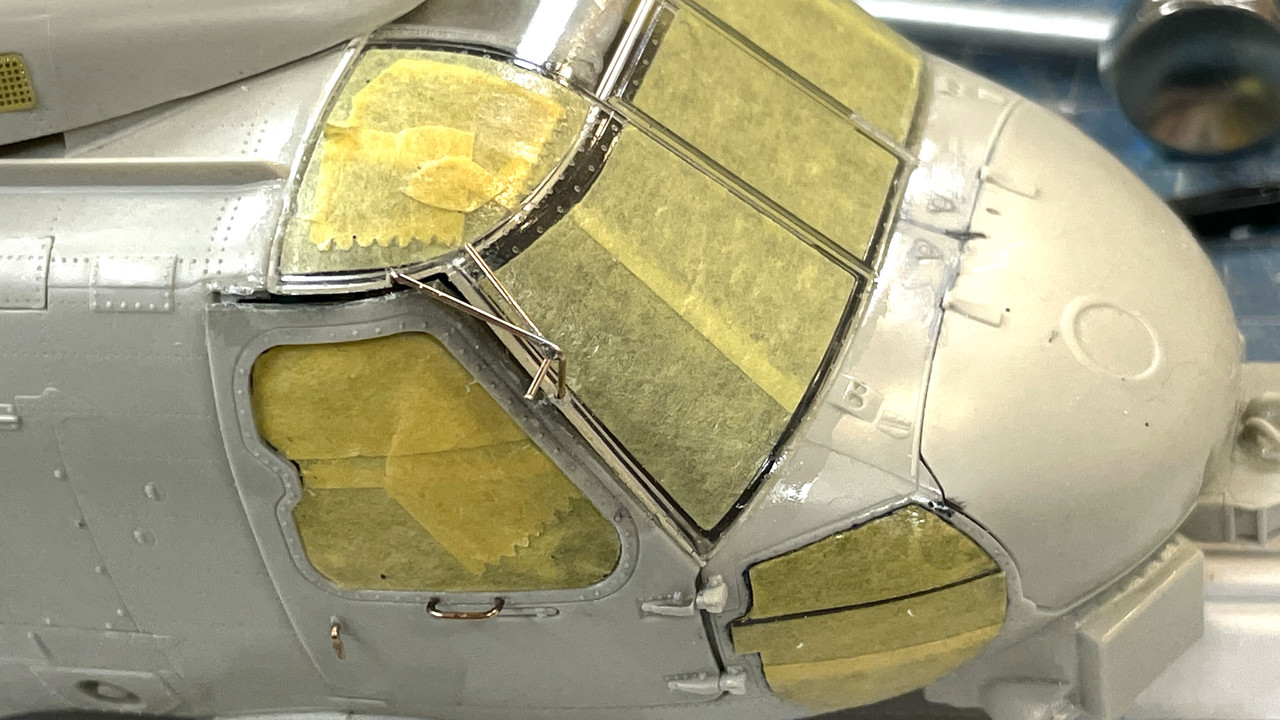
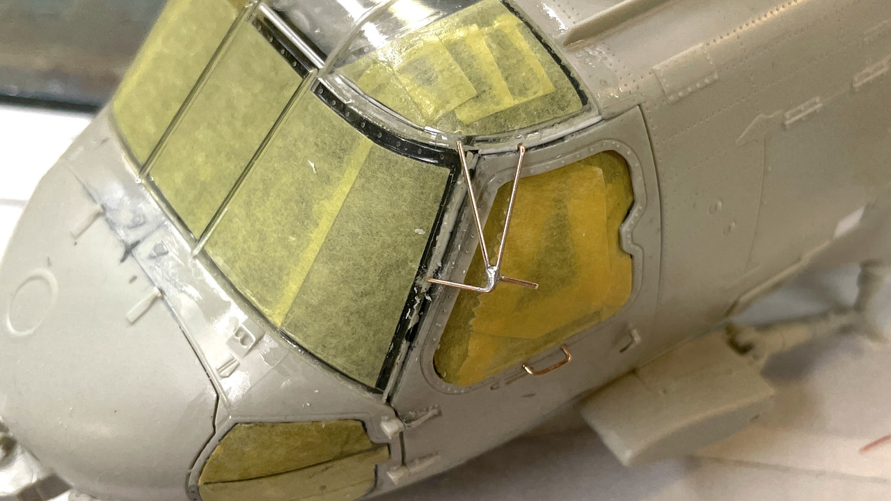
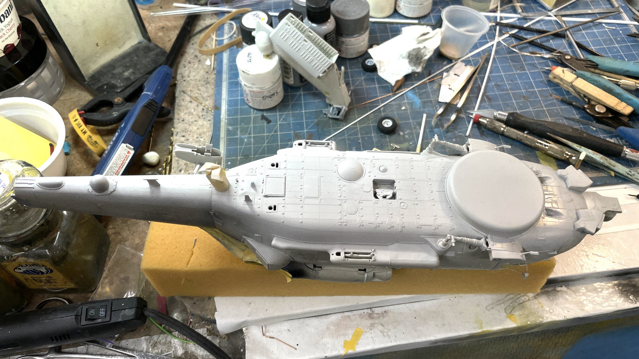
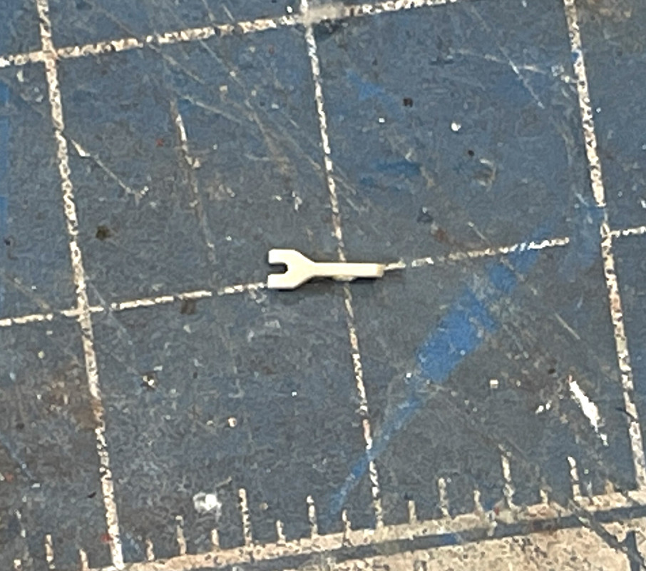
I used the tail rotor image to create a index motor head. I didn’t go the full route with the roller and pin, but it’s shaped so it fits the crown on the tail rotor rear. I was wondering why that part was shaped that way… now I know. (and so do all of you). Looking at this close up, it’s still a bit big and I can reduce it.

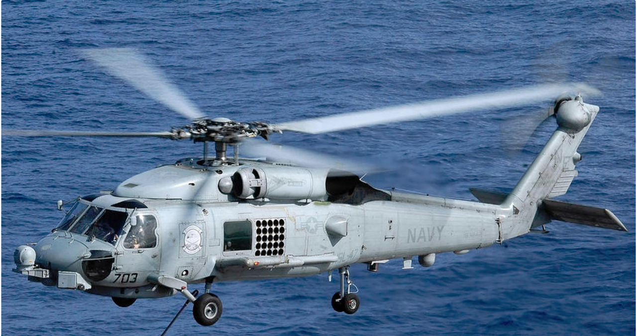
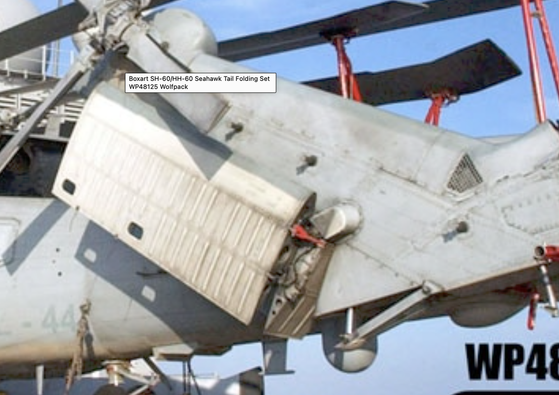
We’re at the stage of the model that’s equivalent to the punchlist phase of building a new house. The last little bits and pieces take an iordinately long time. Another thought I have is just how much more complicated the helicopter became when they turned the Blackhawk into the Seahawk. All the folding stuff adds mechanical complexity AND sensors to ensure that the flight crews knows everything is in the right place. Blackhawks don’t need a blade indexing motor.

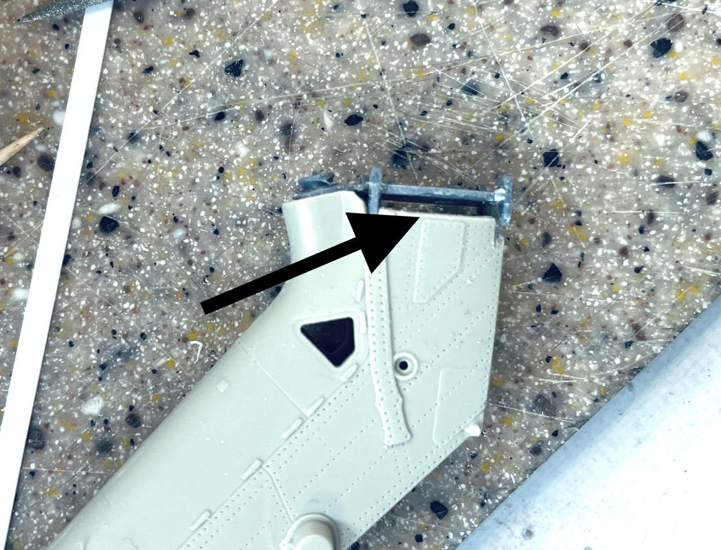
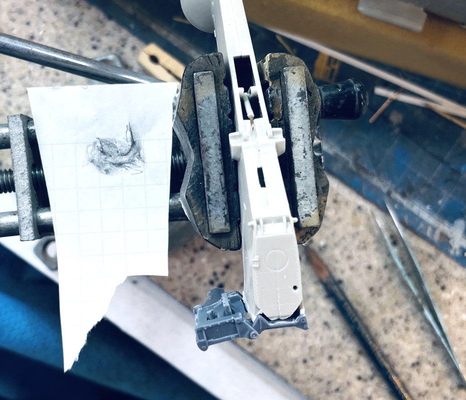
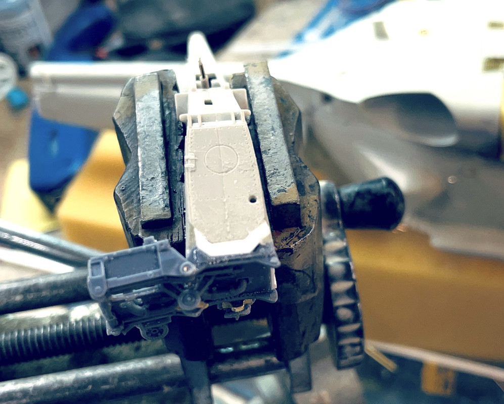
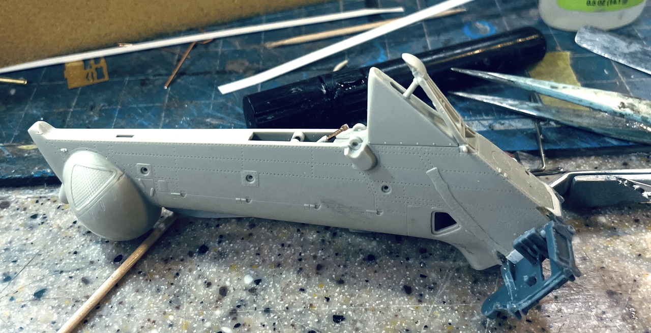
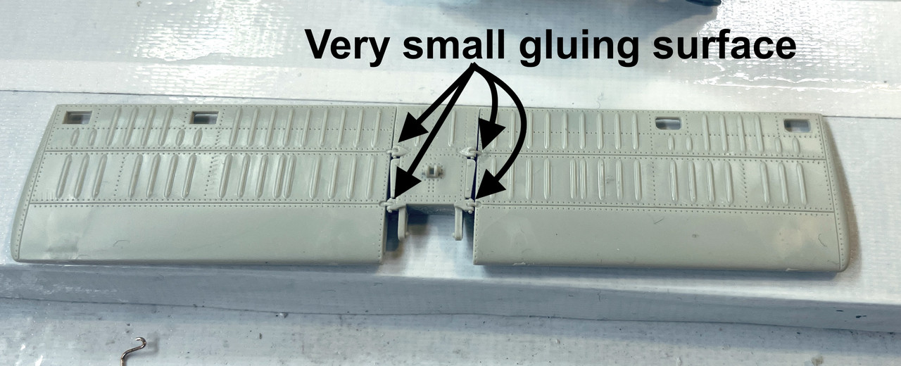
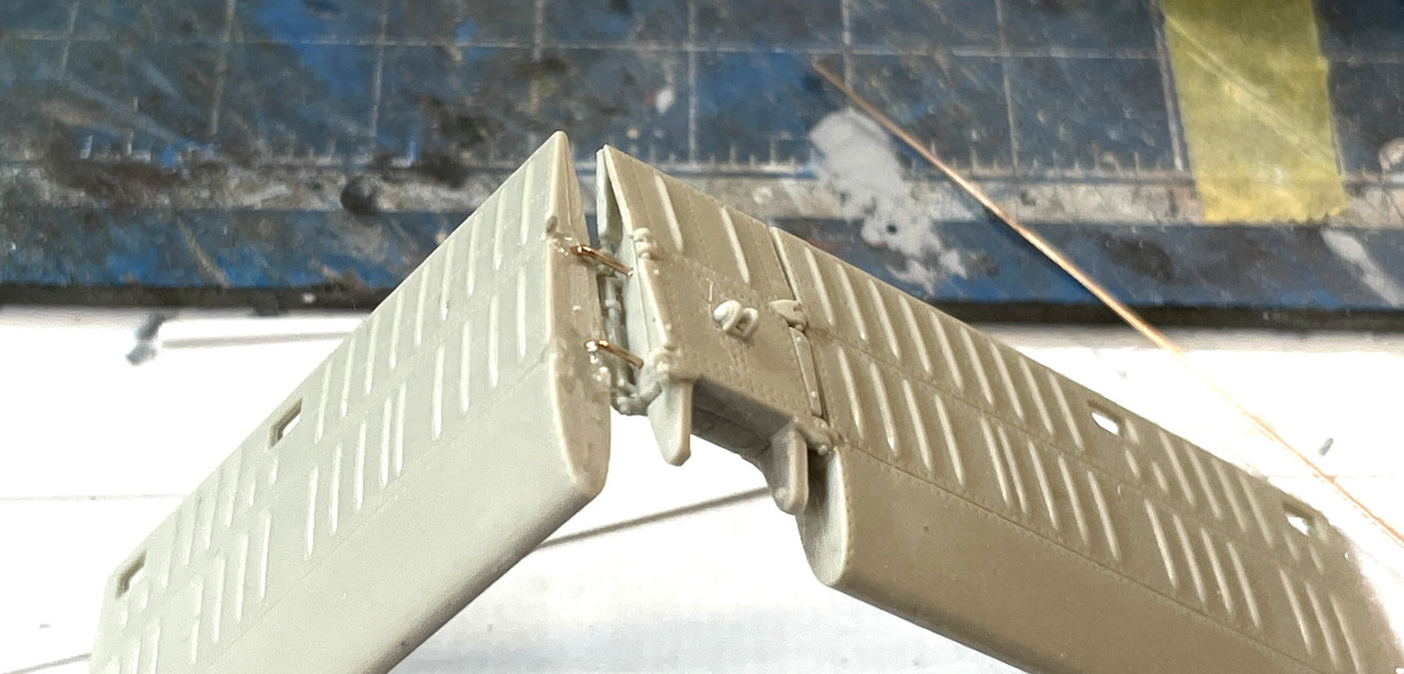
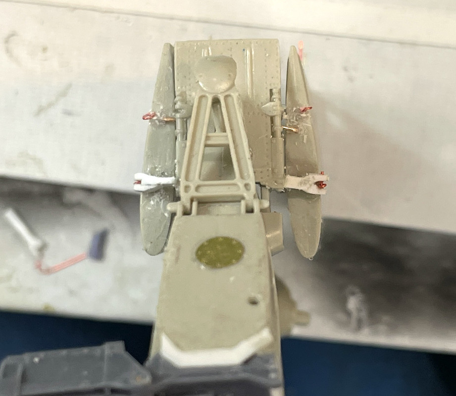
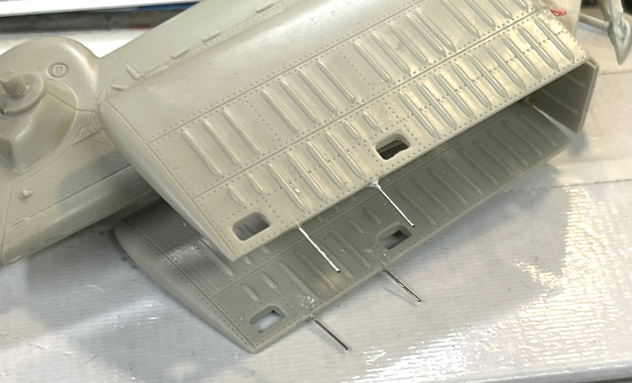
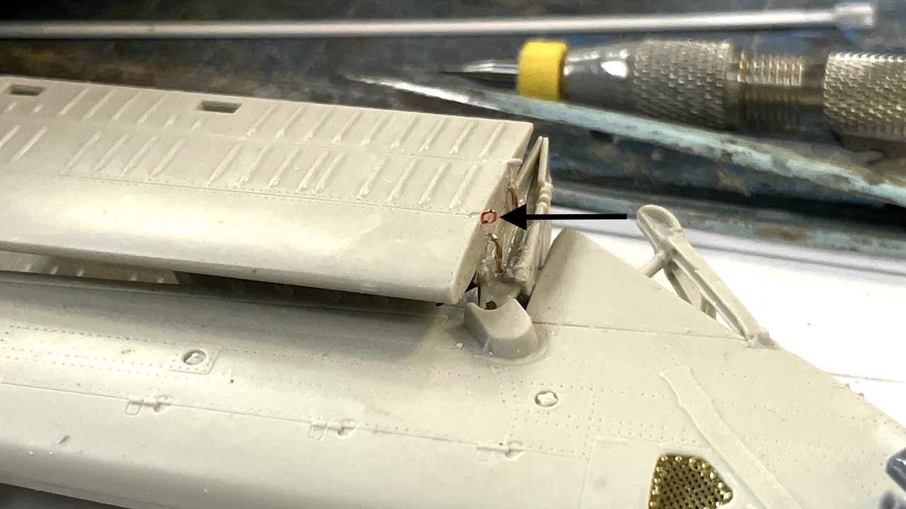
I started cobbling together the tail plane lock bars. They attach to the hinge point on the tail plane and clamp to the edge of the center section. I added doublers to some styrene stock that I’ll shape to make the contours more like the real ones. They have to dry overnight since when I tried to shape them before they were fully dry, they didn’t like it.

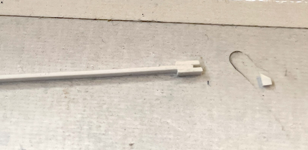
I also had to add back a hinge point so it would have something to hold onto. The kit’s part disintegrated when I had to rip off the already-glued tail panels.

I started painting stuff! This is a milestone. I painted the tires rubber black which finished the smaller tail wheels.

remember I made some round masks for the small wheel hubs a while ago when I painted them white.

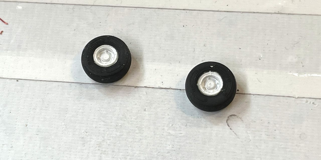
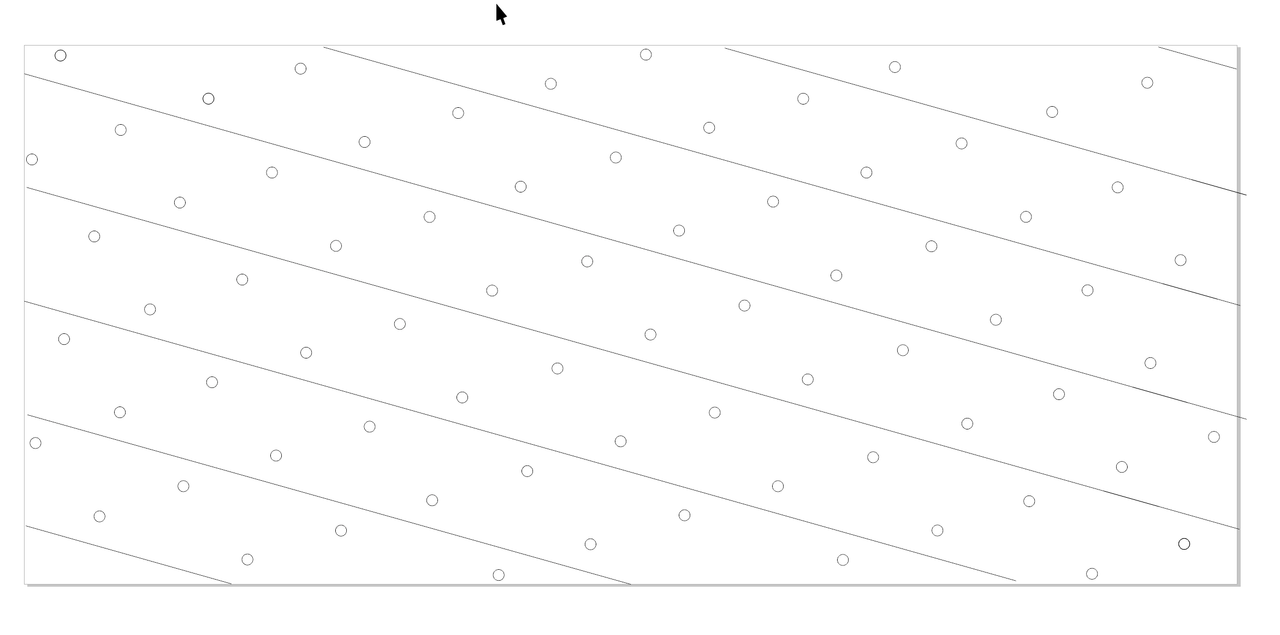
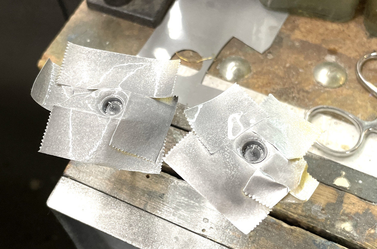
But for the large main wheels I didn’t paint and mask the hubs first. The tie-down ring protrudes from the wheel and I didn’t want to break it by masking on top. In this case, using the same dividers with one leg sharpened to a chisel edge, I cut the circles, but used the piece with the holes.

I then sprayed them a base coat of lacquer, in this case some Tamiya silver, and I go back and paint the while. The lacquer acts as a barrier and prevents the black from leaking through. I always put on DullCoat when I’m going to change colors and don’t want any blending.

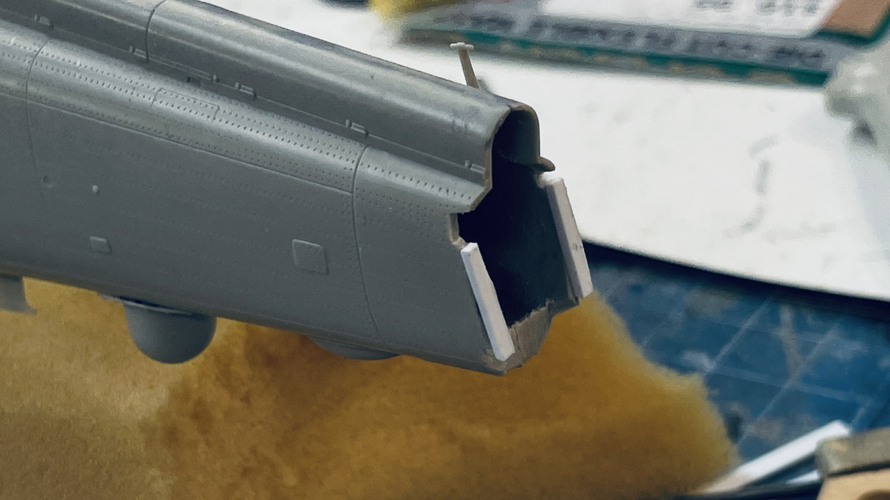
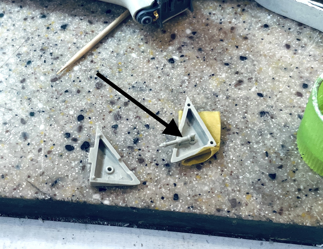
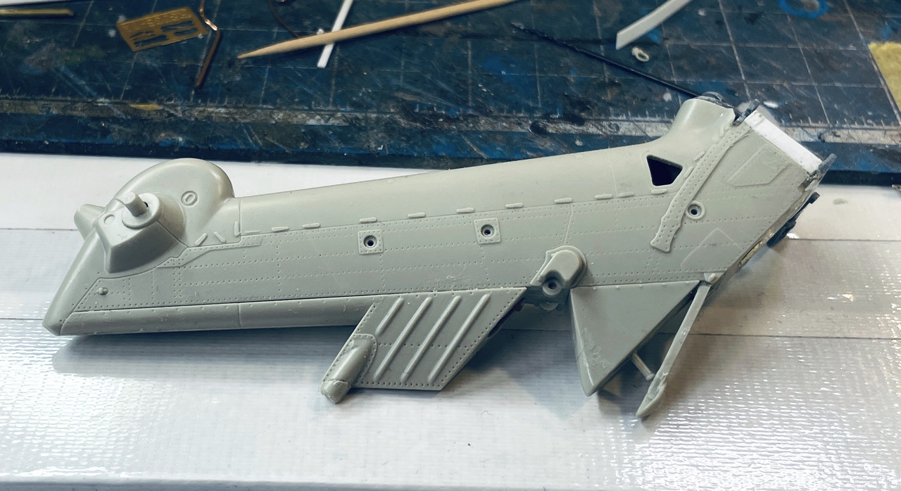
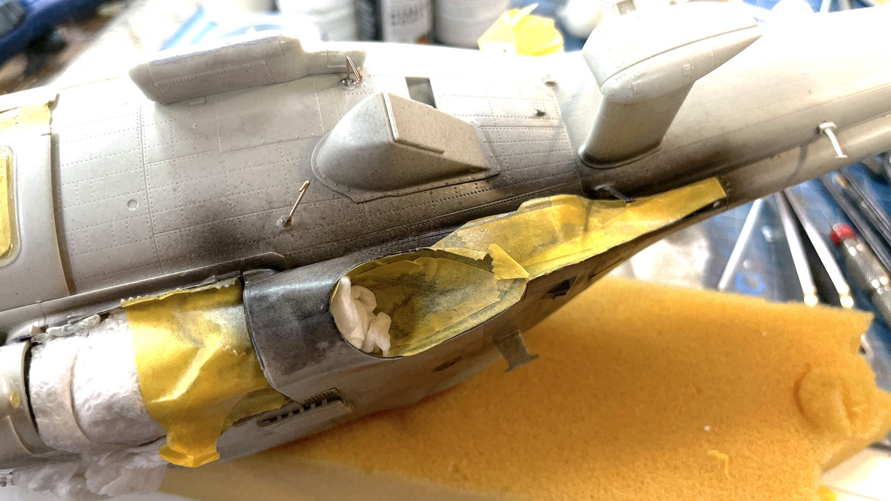
The last things I painted was the exhaust chutes. I first shot the turbine outlet some dark iron and then went back and did the whole area with flat black taking car to not overcoat the previously shot dark iron.

This is flash shot (which I rarely use) that lights up the innards.

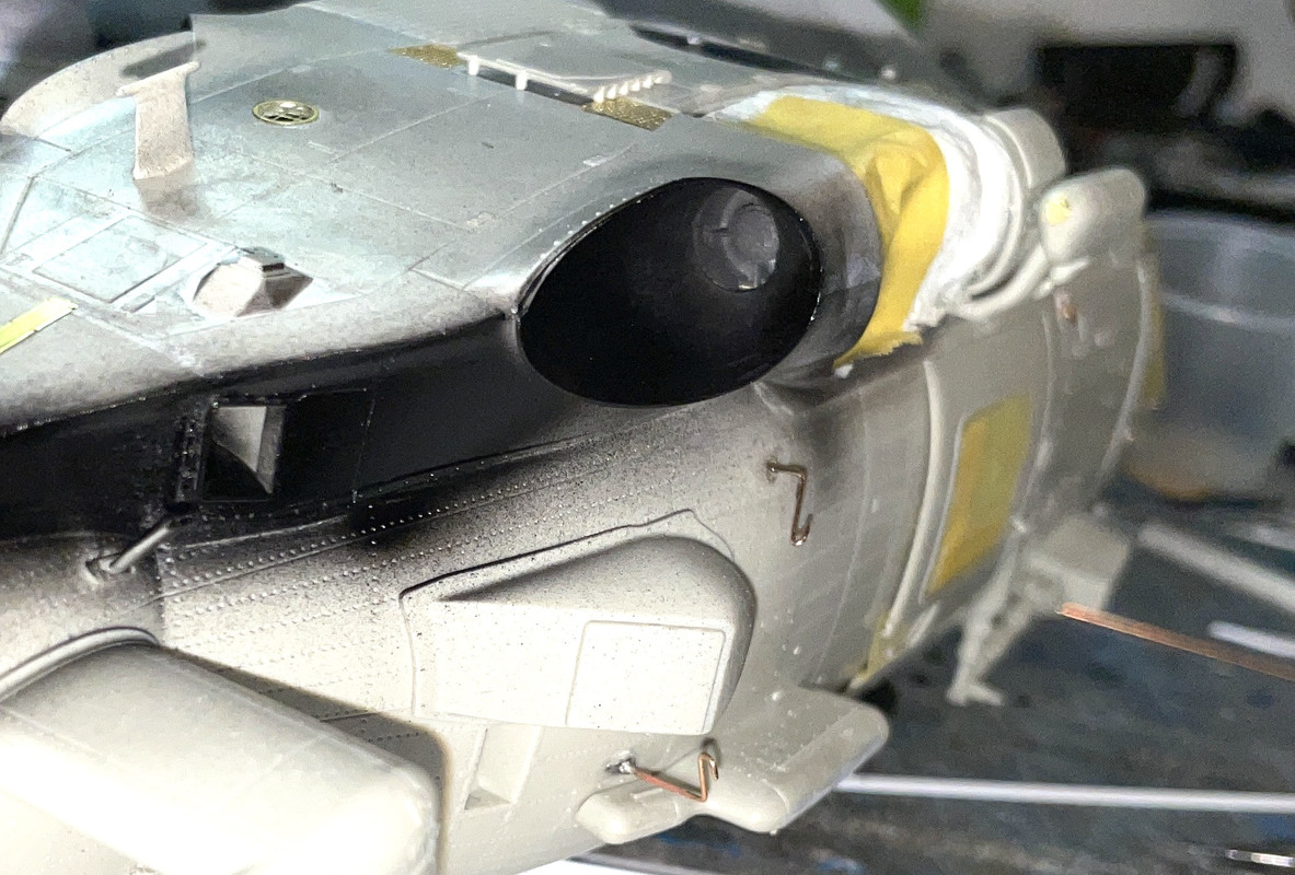
And here’s a non-flash shot showing the whole area. This will be masked to the proper outlines as needed. The last thing I did was shoot this paint with DullCoat to seal the black and make good base for the body colors. BTW: that chute where you can see a little bare color is the APU’s exhaust which would be in that part of the overhead.

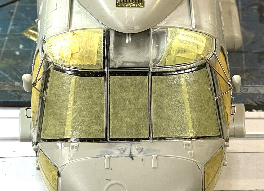
I have to write a real punchlist to ensure that I don’t miss anything. It’s a relief that all the ResKit work is now complete and reasonably successful. I still have to solder together the rear view mirror brackets, which I’m doing tomorrow.

I also glued on the big radome on the bottom since it was time.

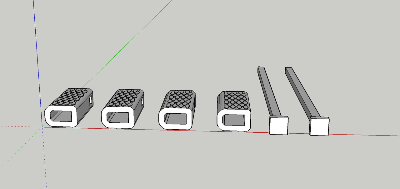
I need to build a base and want it to duplicate the surface of a hangar deck. I’m going to 3D print my own tie down cups. They’re available from Reedoak, but they’re expensive and I want to keep my powder dry to buy their 1/35 Naval Aviation service people.

What is the diameter of the modern USN tie down cup?

Found out…. 9.8" and made the drawing about 20 minutes and can produce a ton of them for $0.25 of resin.

Now I just have to the rest of the design.

4 Likes

I am drawing a US Navy wheel chock set and the base itself which will duplicate the surface of a hangar deck. The models is a scale 60 feet long so the base is going to be 30" by almost 14" with 60 tie down pucks. Reedoak wanted $5.50 USD for 14 pucks plus shipping from Europe. It would probably be $50 just for the tie downs. I’ll print 60 for about $1.00. BTW: with the 3D work that I’ve sold over the last two years, the printer is paid for more than once, so any work I do is a direct cost savings to me.

Here’s my hangar floor design. I eyeballed the plate and tie down spacing. I looking at a series of hangar deck images, it looks like the plates are 8’ wide and the tie downs look like they’re 2’ off the seams and about 4’ apart. Does anyone know the actual dimensions. I making it on a bias so it’s more interesting.

I’m also drawing a set of 1:35 Naval wheel chocks. It looks like the only sizes commercially available are 1:32, 48 and 72. Now they’ll be 1:35s also.

In the shop I did some stuff also. Got the tail plane clamps done. One of my fabricated clamps worked okay, but the other fell apart during shaping. I chose a different approach making it out of a solid piece. However, as you can see they’re not exactly the same. They’re on the underside of the tail and difficult to view. I’m calling them done. I also replaced the missing hinge loops on the tail planes that were wrecked when breaking the joints.

I touched up the wheel paint and the rear landing gear. I then went to work making a set of metal rear-view mirror frames. It took a couple of iterations, but got them built.

These small jobs are made very doable with the resistance soldering unit AND the MicroMark ceramic soldering pad that lets you stick the parts into the surface and hold everything still with T-pins. The metal is more scale in appearance than the plastic and a whole lot stronger.

Here’s the right side one being fitted.

And the left side…

And with the mirror housing installed.

There is a slight problem. When looking straight ahead the left side is hanging lower than the right. Fixing that (if I fix it) will have to wait until Monday.

4 Likes

I Redid the left side mirror frame. It’s still not perfect, but it’s better. It really doesn’t take very long to bend and solder a new one togeher.

Painting has officially begun today with the masking of the exhaust channels. This was a finicky masking job because of curves and concave faces. After masking I coated the edges with clean to better seal them.

I was tired of bending and un-bending the static discharge probes and scrapped them and replaced them with 0.012" guitar string (I think it’s a B string since I use very like gauge strings). They’re tough as nails… well actually tougher than nails since piano wires is harder than most nails. And they’re very sharp and will getcha!

I broke my last micro drill, but 20 more are arriving shortly from Drill Bits Unlimited.

I mixed up a very light gray, almost white for the bottom color and air brushed all the bottom facing things including the undersides of the horizontal stab. This all has to be masked and that will probably happen on Wednesday.

I then I find these on the HF sprue. Looks kinda like the support struts to hold the horizontal stabs in the folded position. Too late. That boat has left the dock. I tried to remove the homemade ones, but they were just too well glued and I didn’t want to risk any damage. It’s part HE33 and is on the Seahawk-only sprue. There was no mention in the instructions or any information about folding the stab at all. If you’re following along with me and plan on building this model, now you know. There are parts to fold the stab, but they just don’t tell you. Now you’ve been told.

3 Likes

Looking good. Thanks for the heads up on the folded stab support too.