Korean War AF-2 Guardian "Hunter" - 1/48 Special Hobby Build

I do actually build my own stuff, in addition to shepherding the “epic” B-17F 1/48 Luscious Lady build to the finish line.

This build is of a Special Hobby 1/48 AF-2 Guardian in the “Hunter” configuration. I had entered it into the old forum Korean War campaign, but the build schedule meant it really was “never gonna happen” for me. :-1:

Anyway, here is the specific subject.

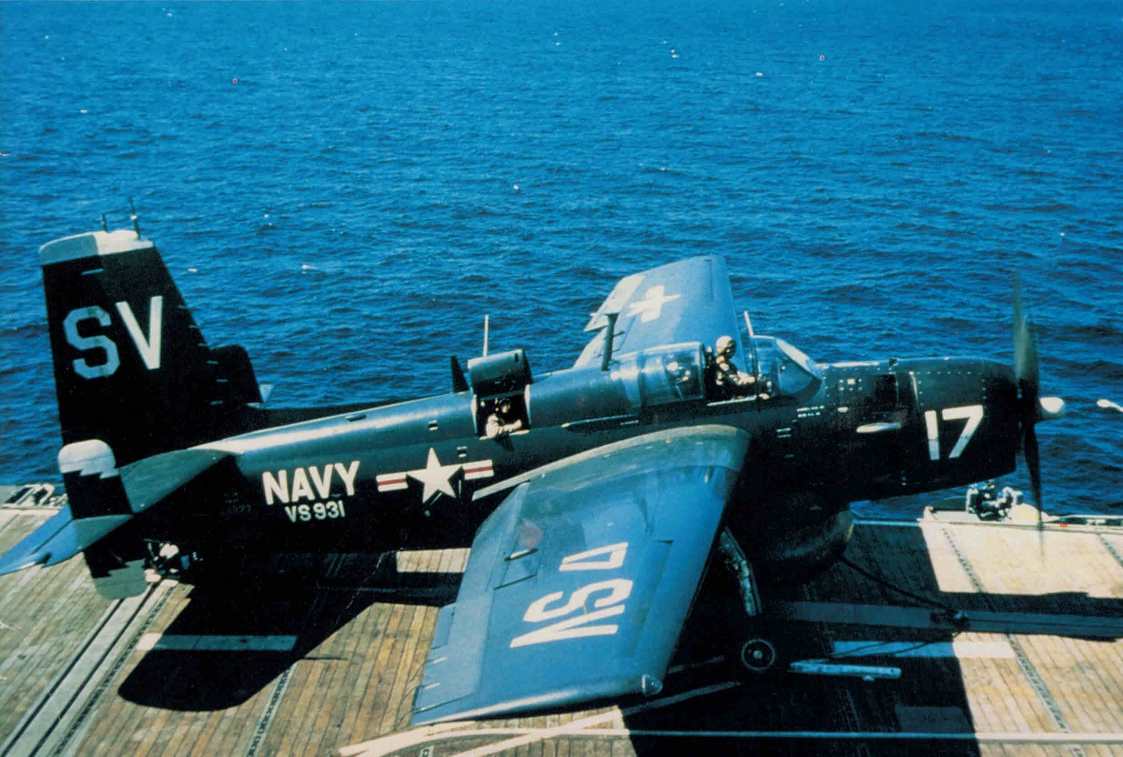
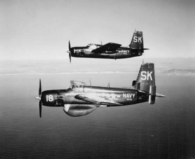
which belonged to VS-931, assigned to various carriers during a deployment to Korea in 1952. Here’s a brief history of the squadron that I found online.

VS-931 Antisubmarine Squadron was activated at Willow Grove Naval Air Station in Pennsylvania on March 1, 1951, during the Korean War and was transferred to Los Alamitos Naval Air Station in California. The squadron was sent abroad on the USS Sicily and operated near Japan and Okinawa. Upon transferring to the USS Badoeng Strait, the Squadron went to Korea on two different occasions to protect the US Naval fleet from enemy submarines. There were several transfers back and forth between the two ships and in addition, the squadron was stationed on land bases at Atsugi and Itami for brief periods. The squadron returned to the States aboard the USS Sicily. Upon returning to Los Alamitos the squadron’s designation was changed from VS-931 to VS-20.

There is no doubt that VS-931 took part in ASW missions in support of the UN Korean war effort, as documented by this online history of the USS Badoeng Strait (CVE-116)

Badoeng Strait strait made two more Korean War deployments, in October 1951 - February 1952 and October 1952 - February 1953, providing a base for both Marine Corps fighter-bombers and Navy anti-submarine planes, depending on the operational needs most critical at the time.

XlqMot

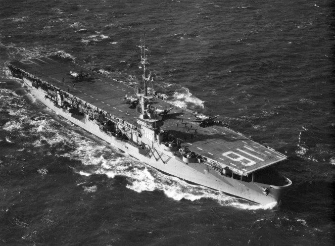
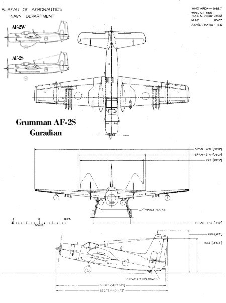
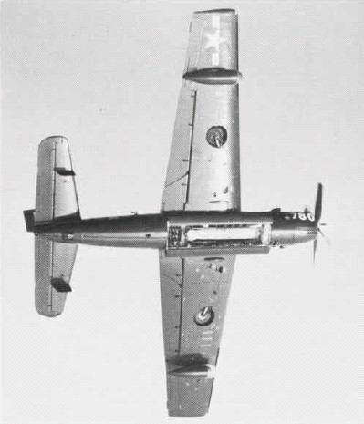
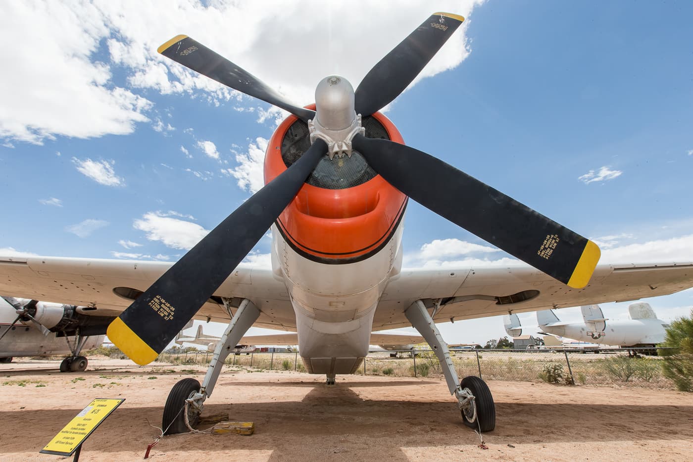
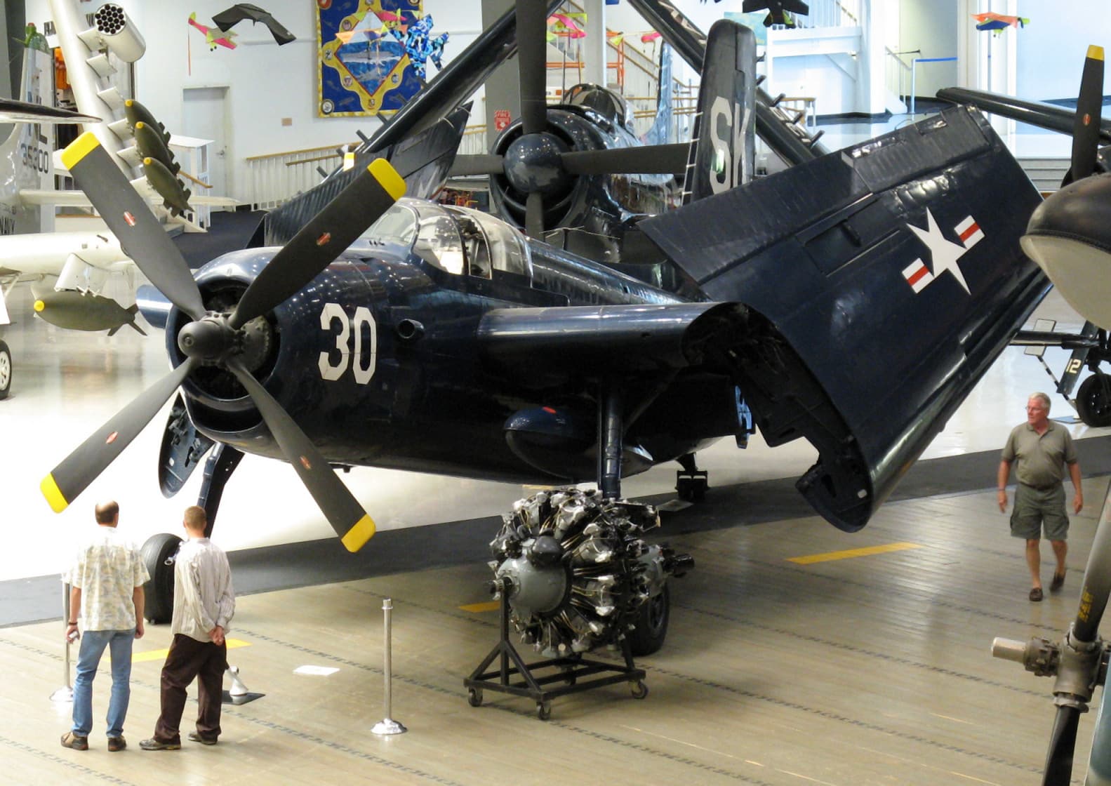
That’s a pretty small flight deck for the largest single-engine propeller aircraft ever operated by the Navy off of aircraft carriers!

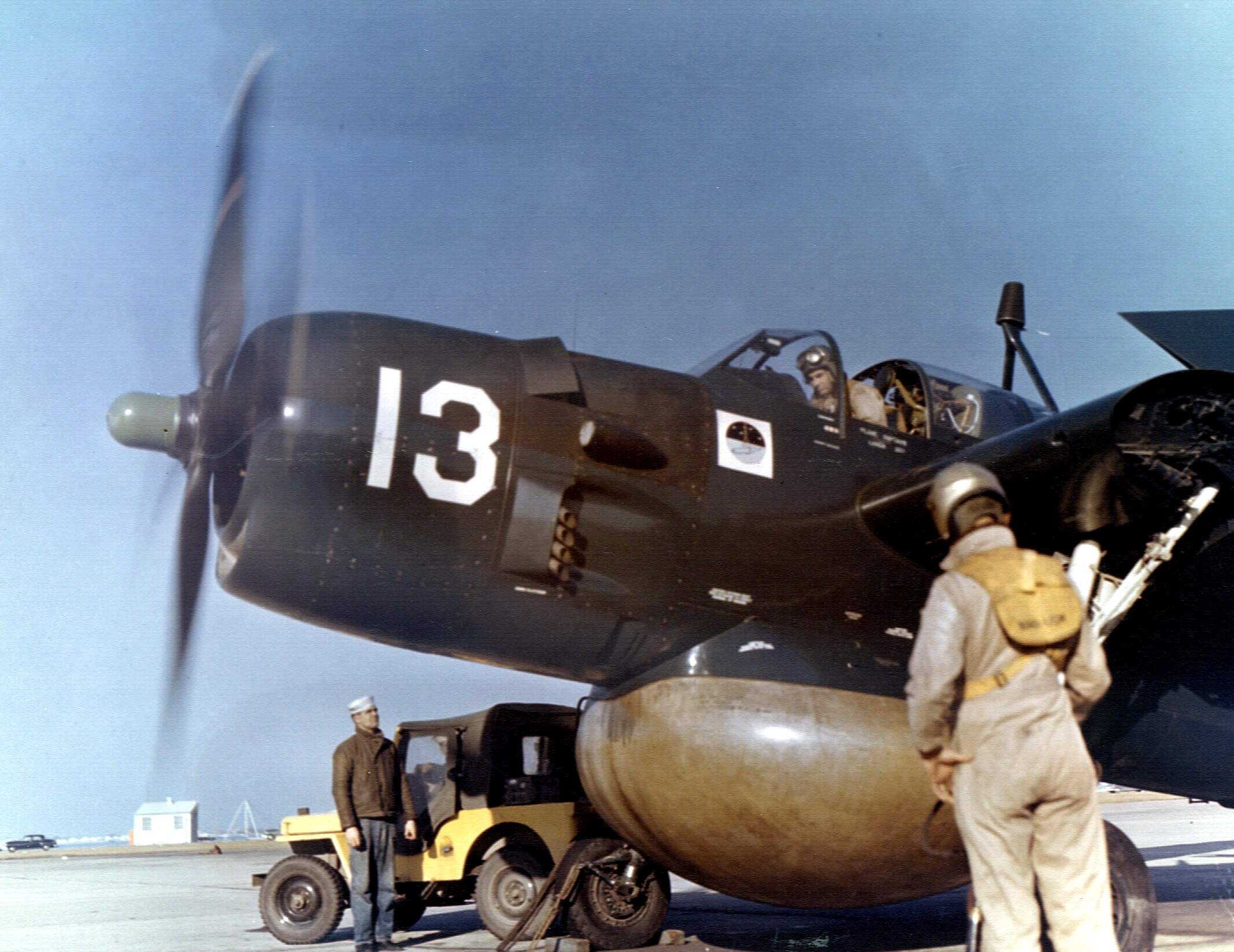
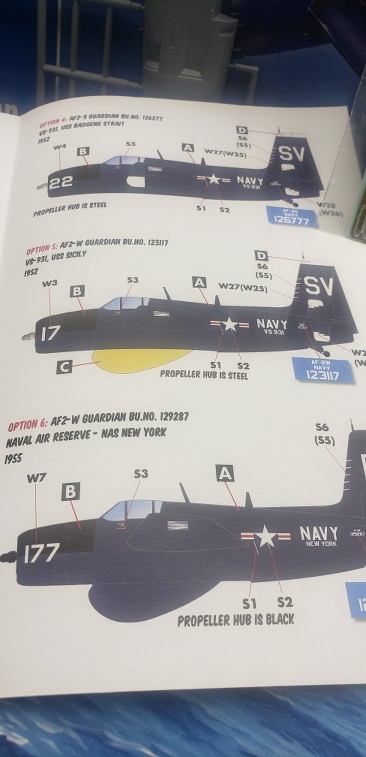
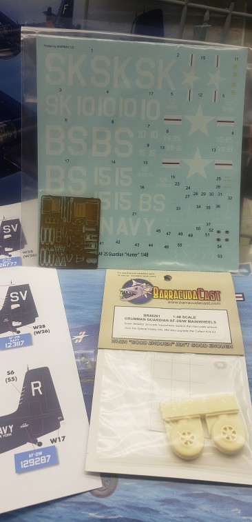
I’m using Caracal decals for my subject, which you can see in the middle.

Aftermarket details will be minimal because there aren’t many! I am using Barracuda wheels with the correct number of spokes in the wheel hubs.

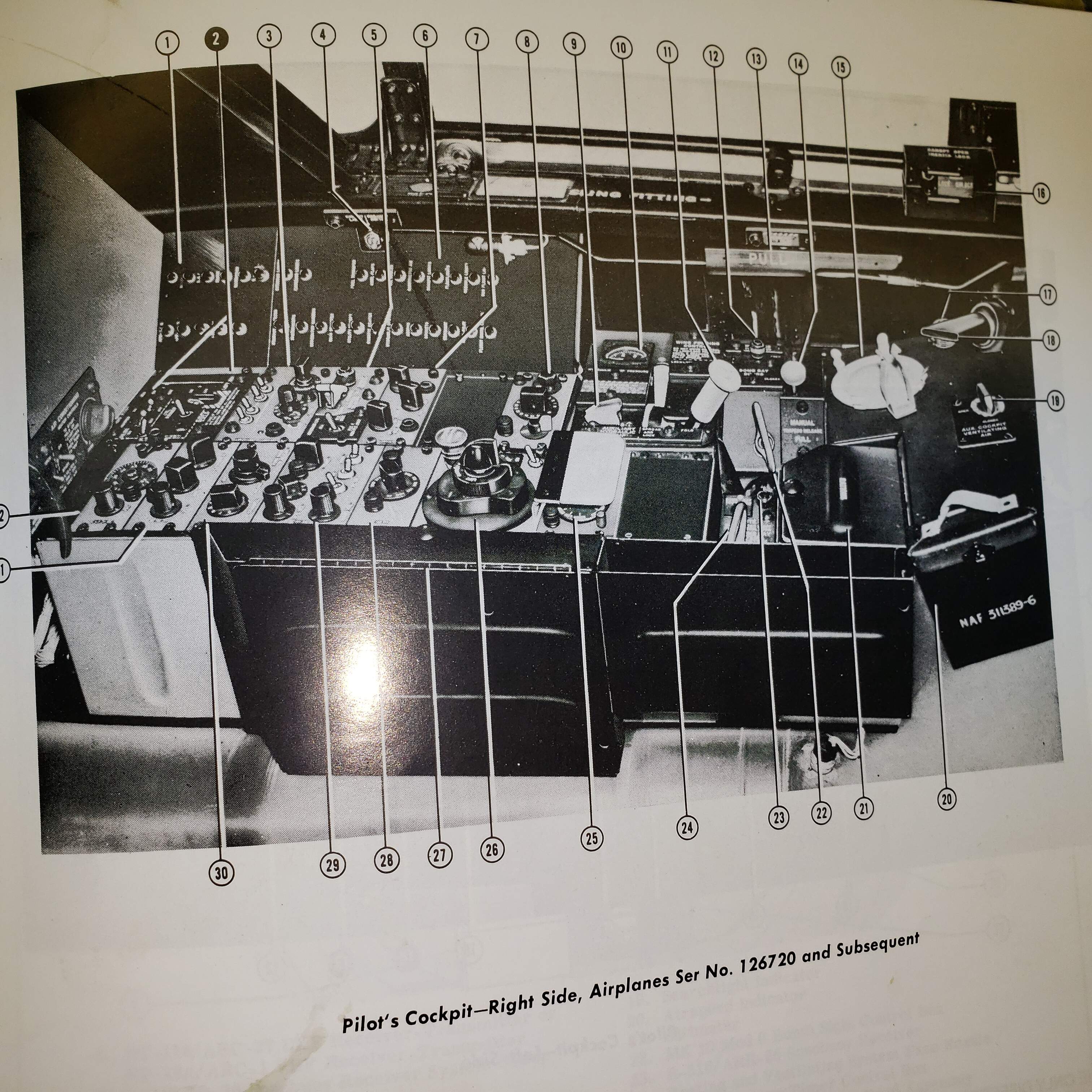
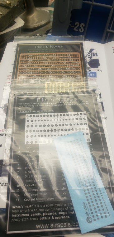
One big downside of these kits is that there are no aftermarket instrument panels and not even instrument decals sheets for them. Just the plastic bevels for the instruments.

To address this, I’m going to have the fun of punching out the Airscale decals below, though I decided the brass bevels were overkill.

For the side panel instruments, I found a copy of a decal online for one version of this A/C (the “MAD Boom” SH issue, which SH didn’t bother to include in the earlier kits.) I downloaded it and printed it out, “adapting” it to the kit with “mixed results,” shall we say. In any event, it’s better than nothing, I think. :wink:

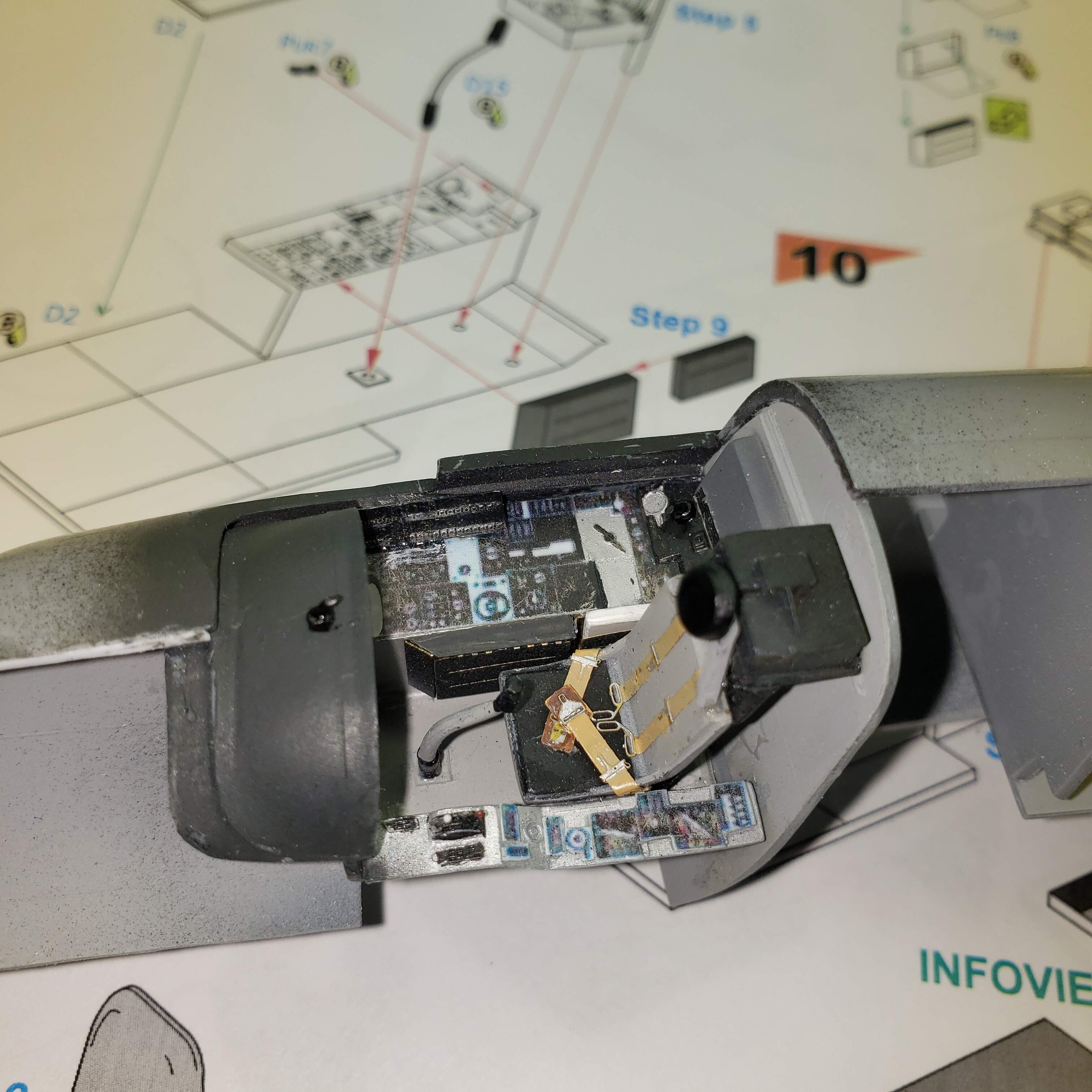
Here are three views of the just-completed cockpit.

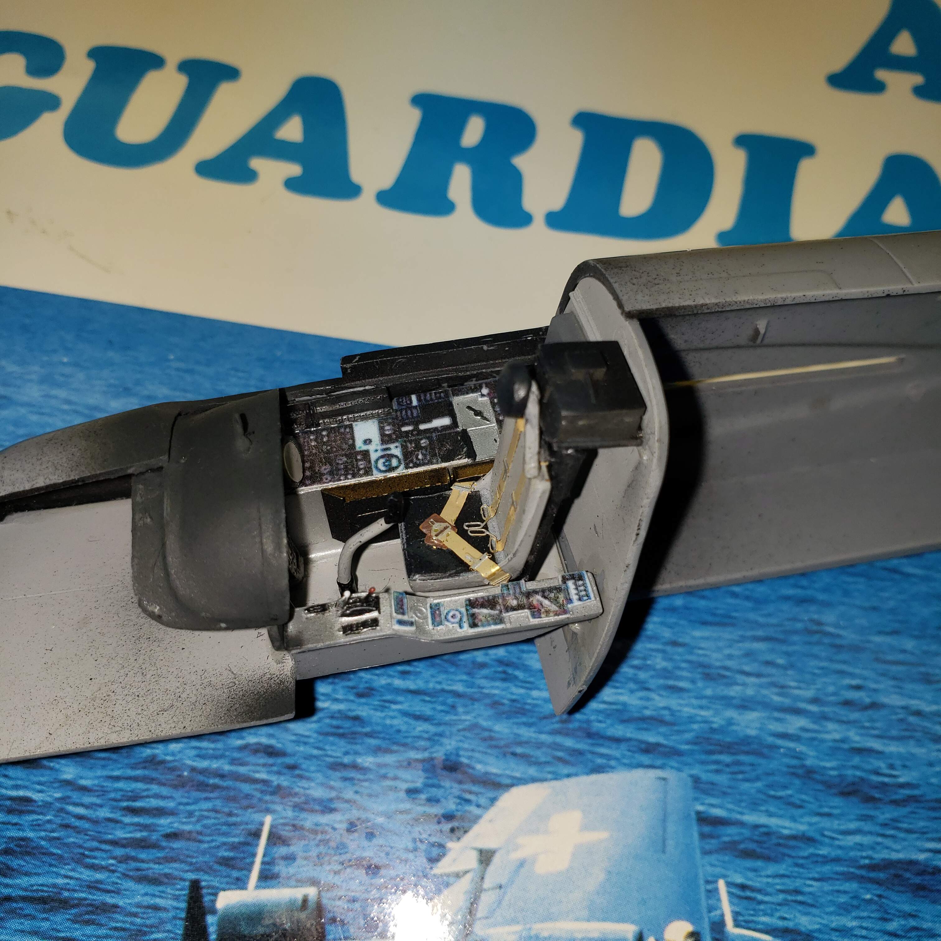
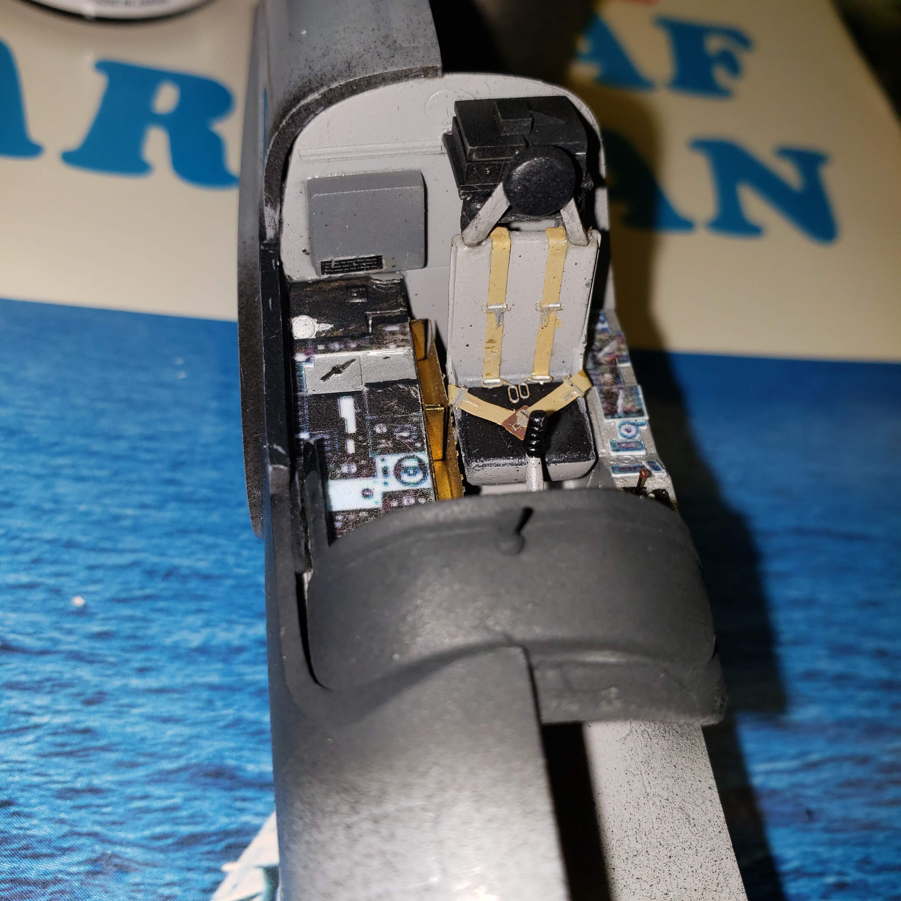
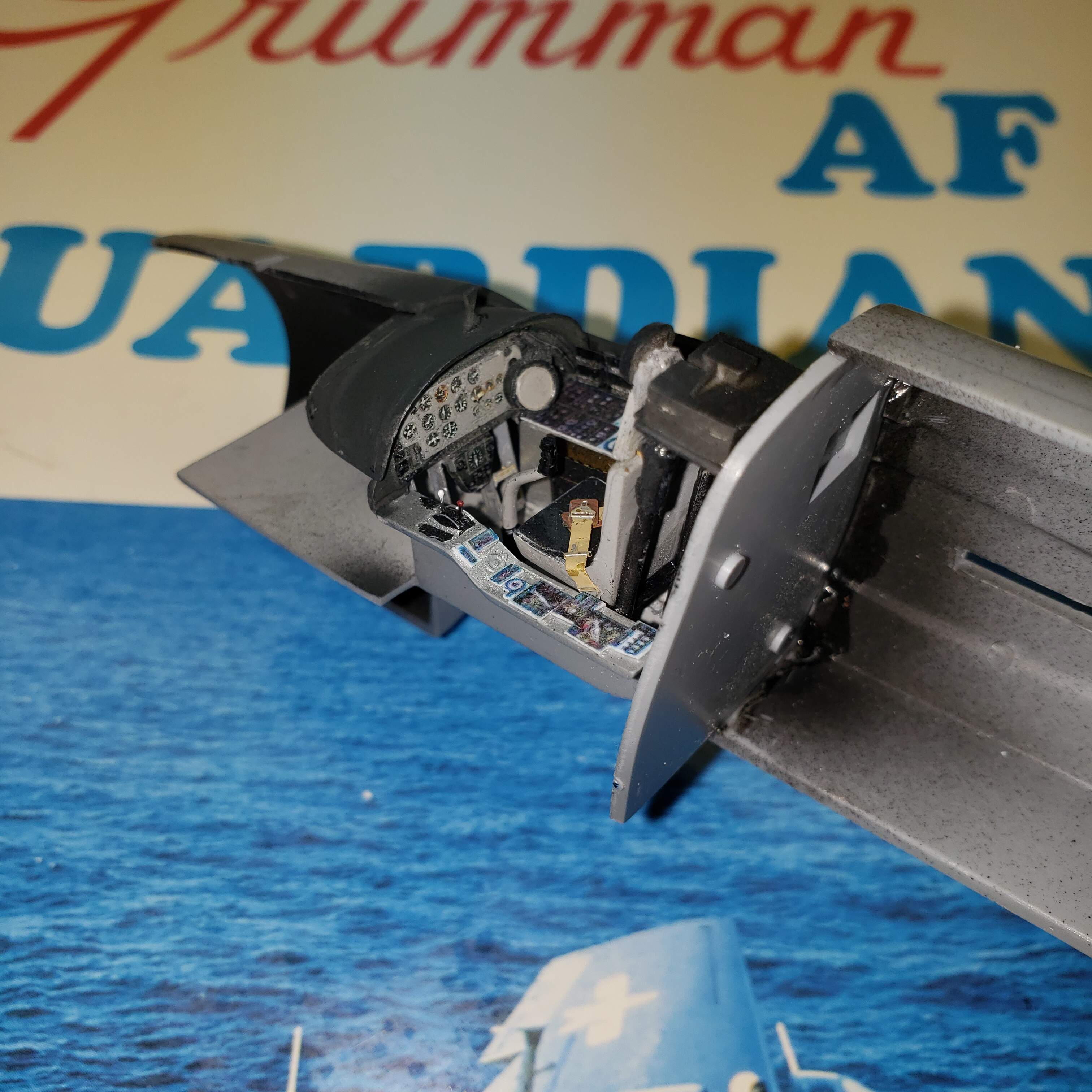
Yes, there is some touch-up needed, and I will probably, carefully, paint the exposed brass of the interiors of the map/documents holders to the right of the pilot seat in the same color as their black exteriors. Only after I installed them did I see how visible they are.

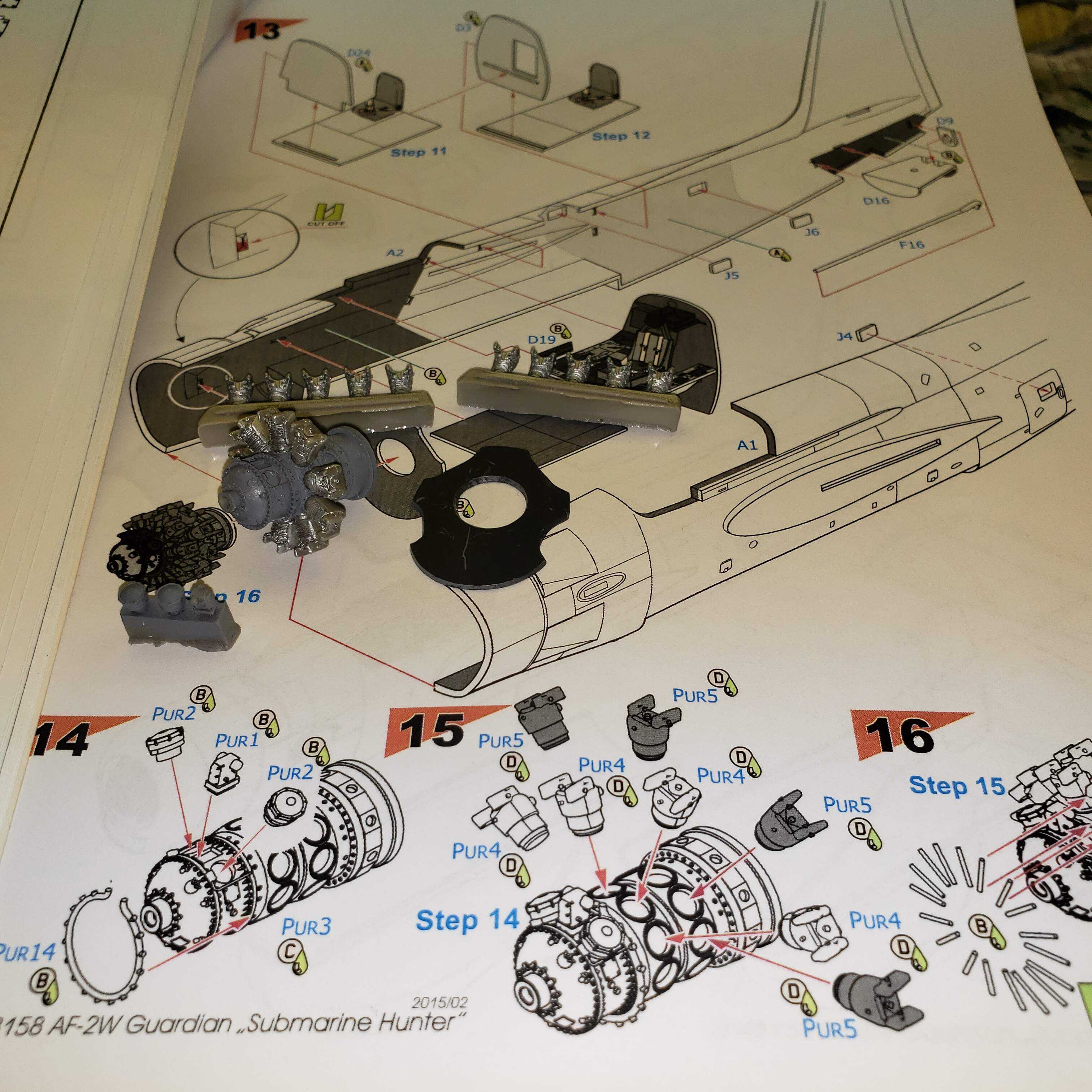
I’ve done better cockpits but lemme tell ya, it was a chore just to get this done! This kit is my first Special Hobby build, and they are DEFINITELY “limited run” products. There was a lot of filing, sanding (and cursing) that accompanied this part of the build, and the instructions were less than helpful. They didn’t even cover installing the instrument panel!!

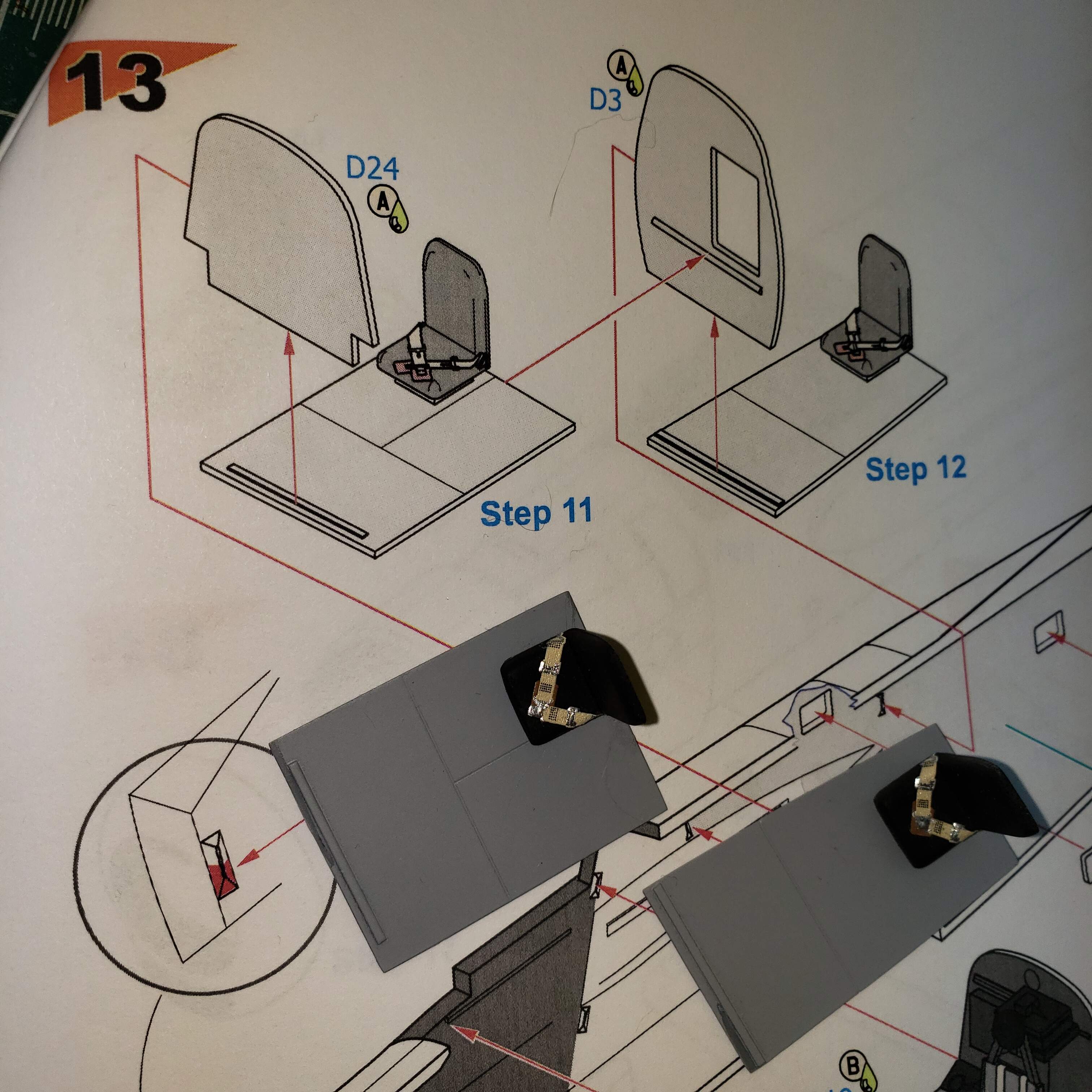
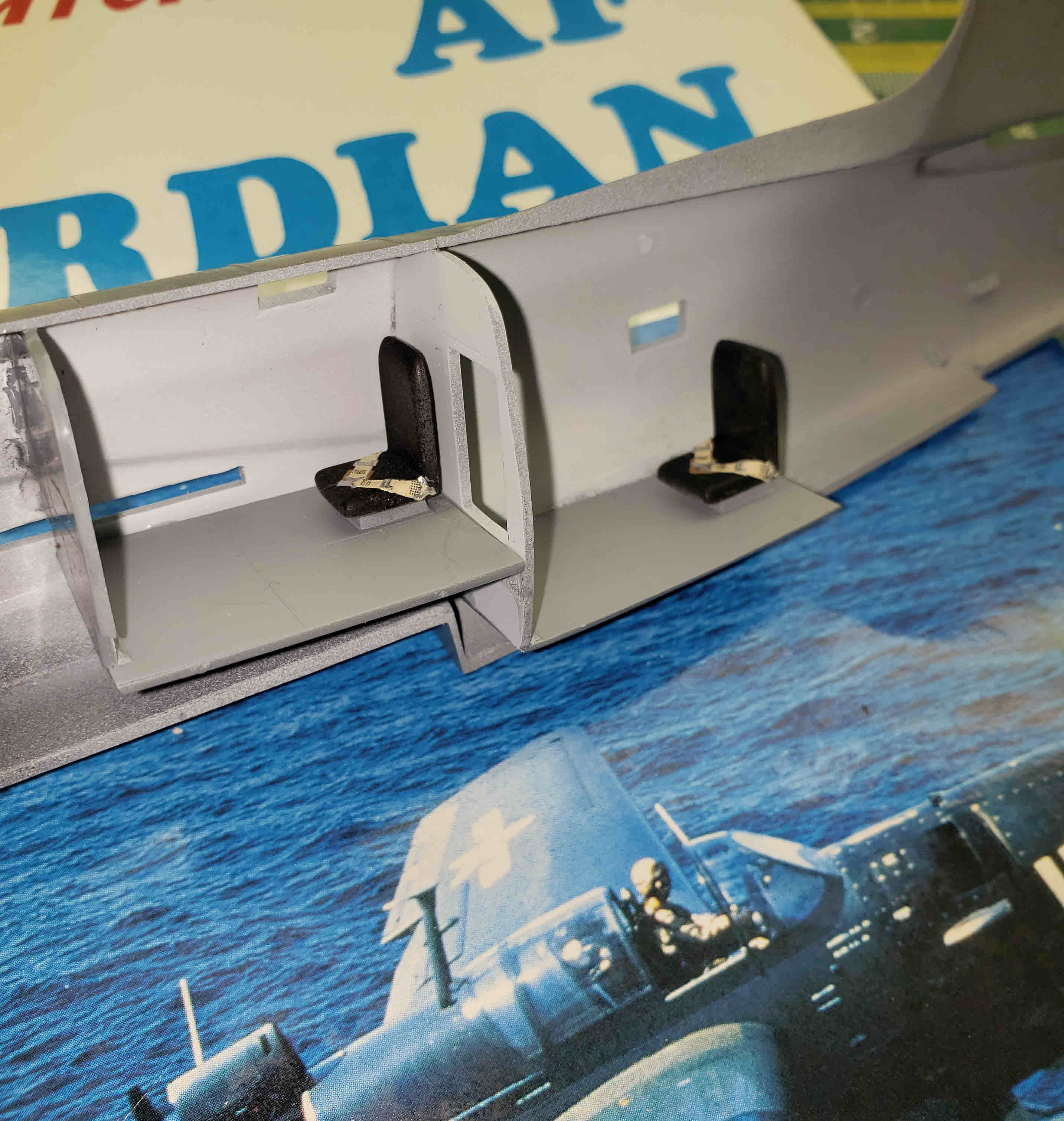
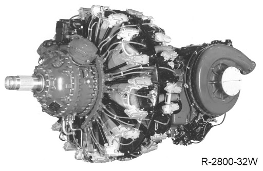
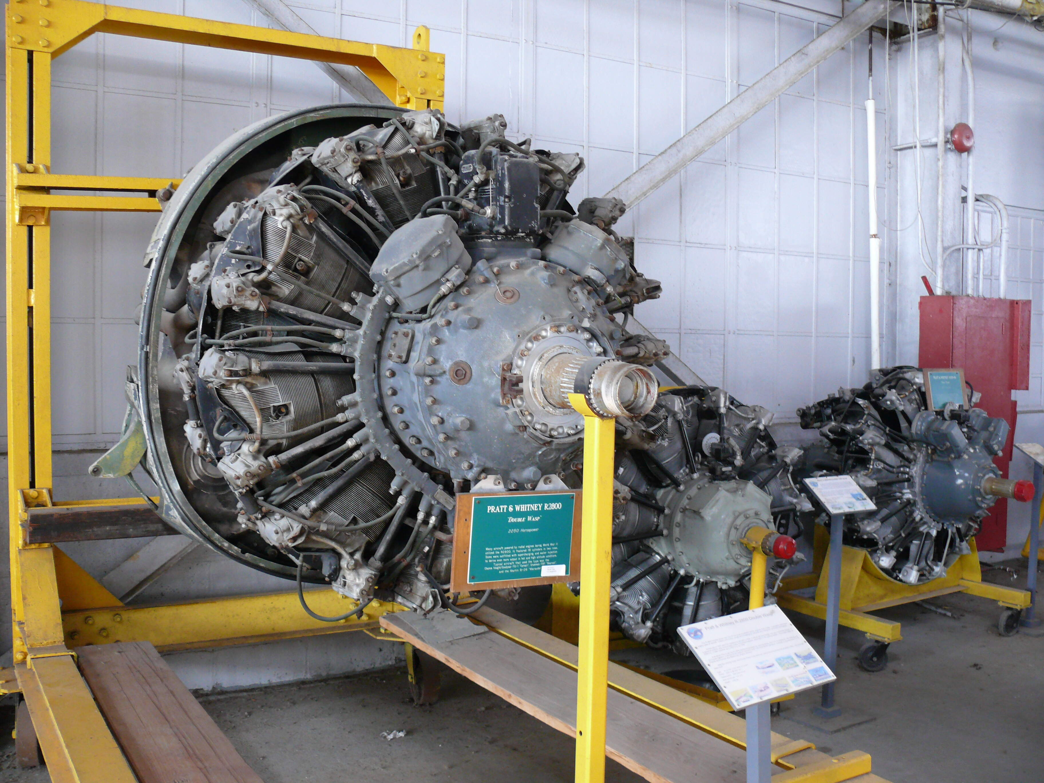
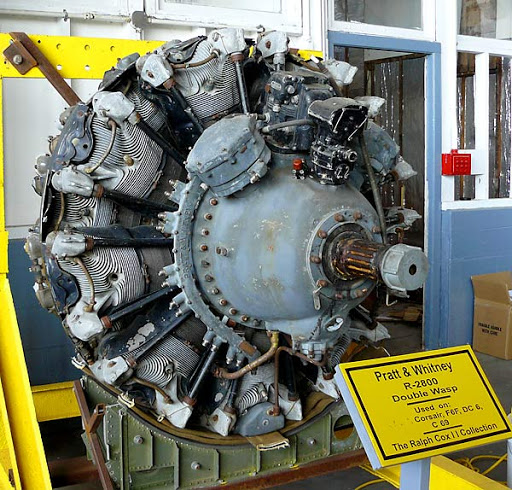
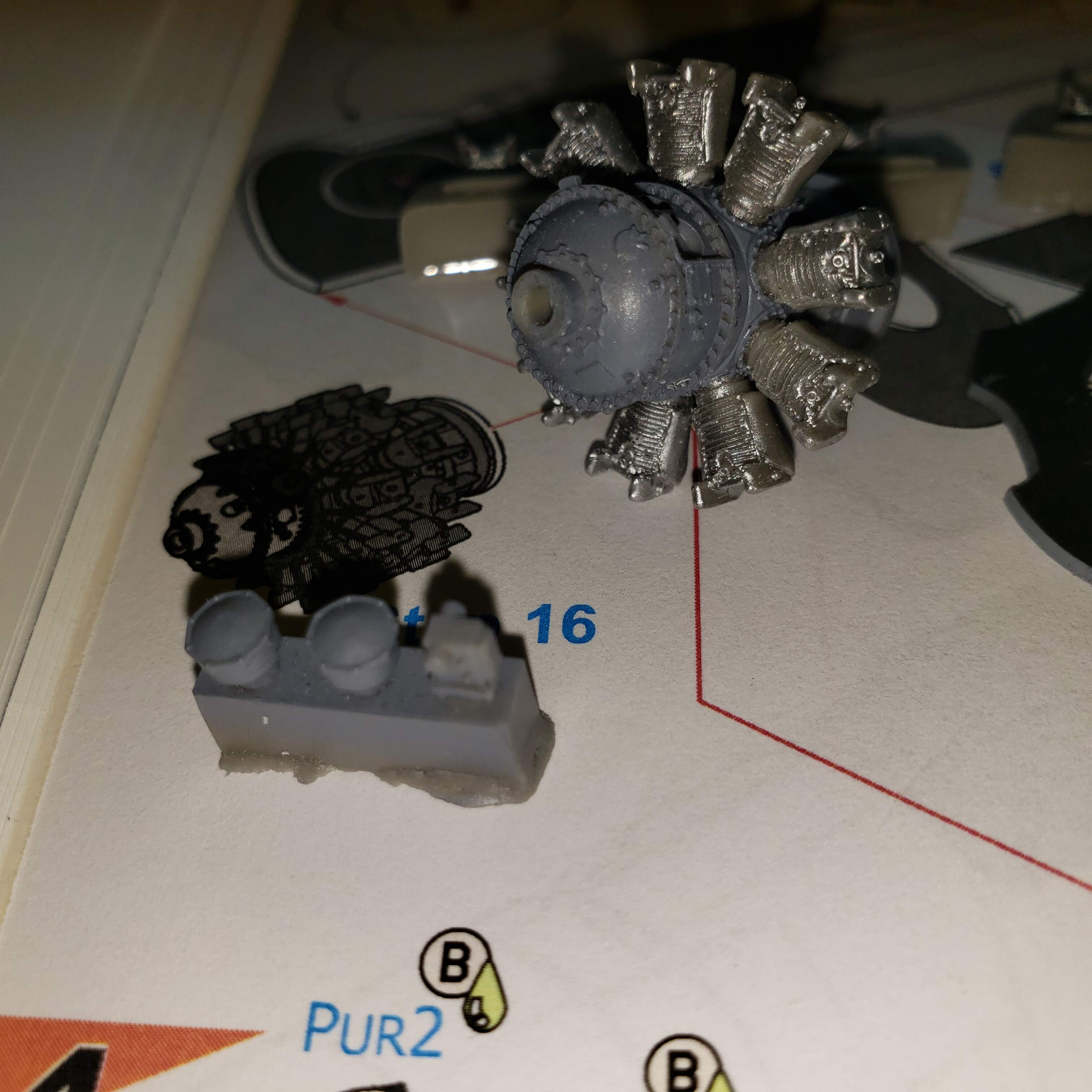
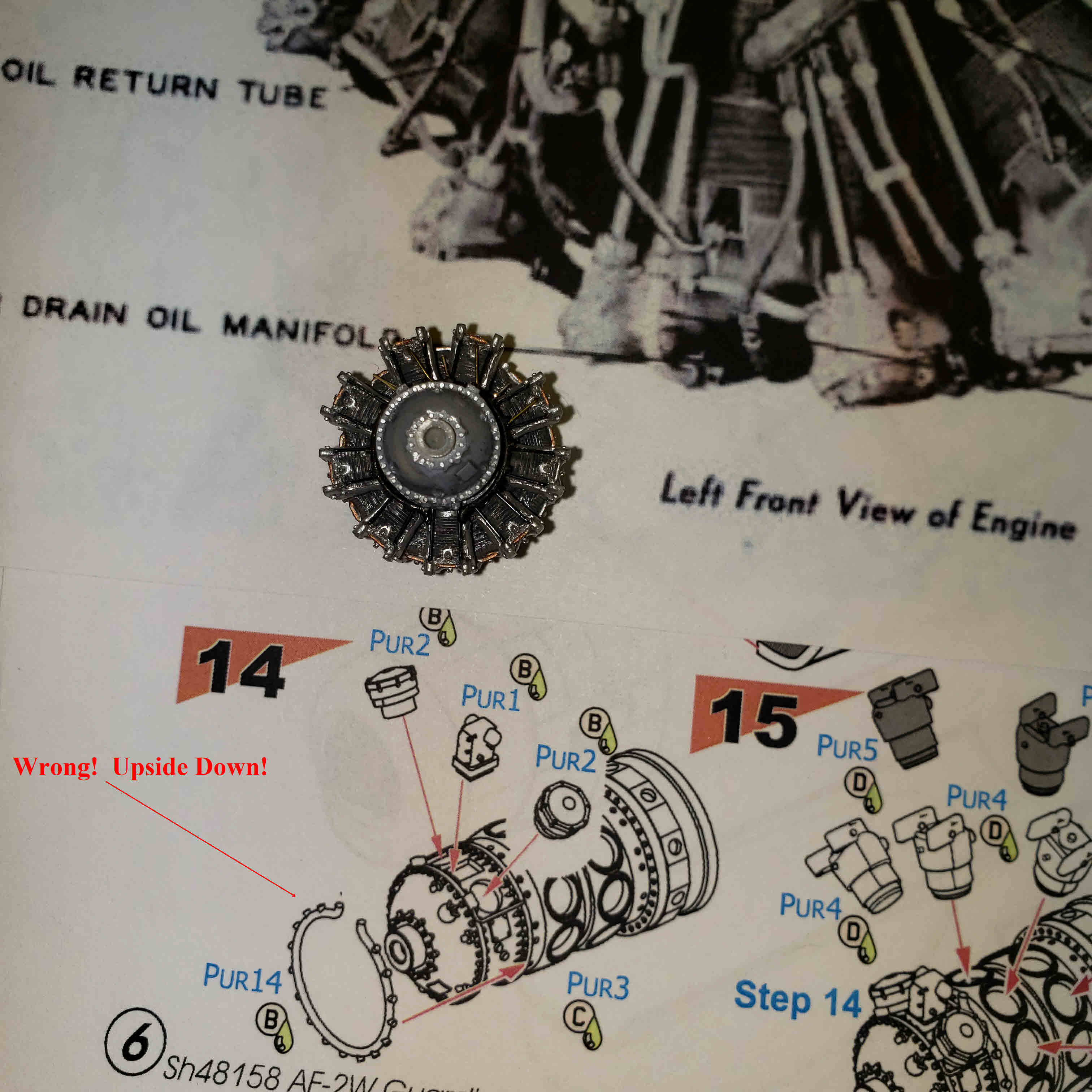
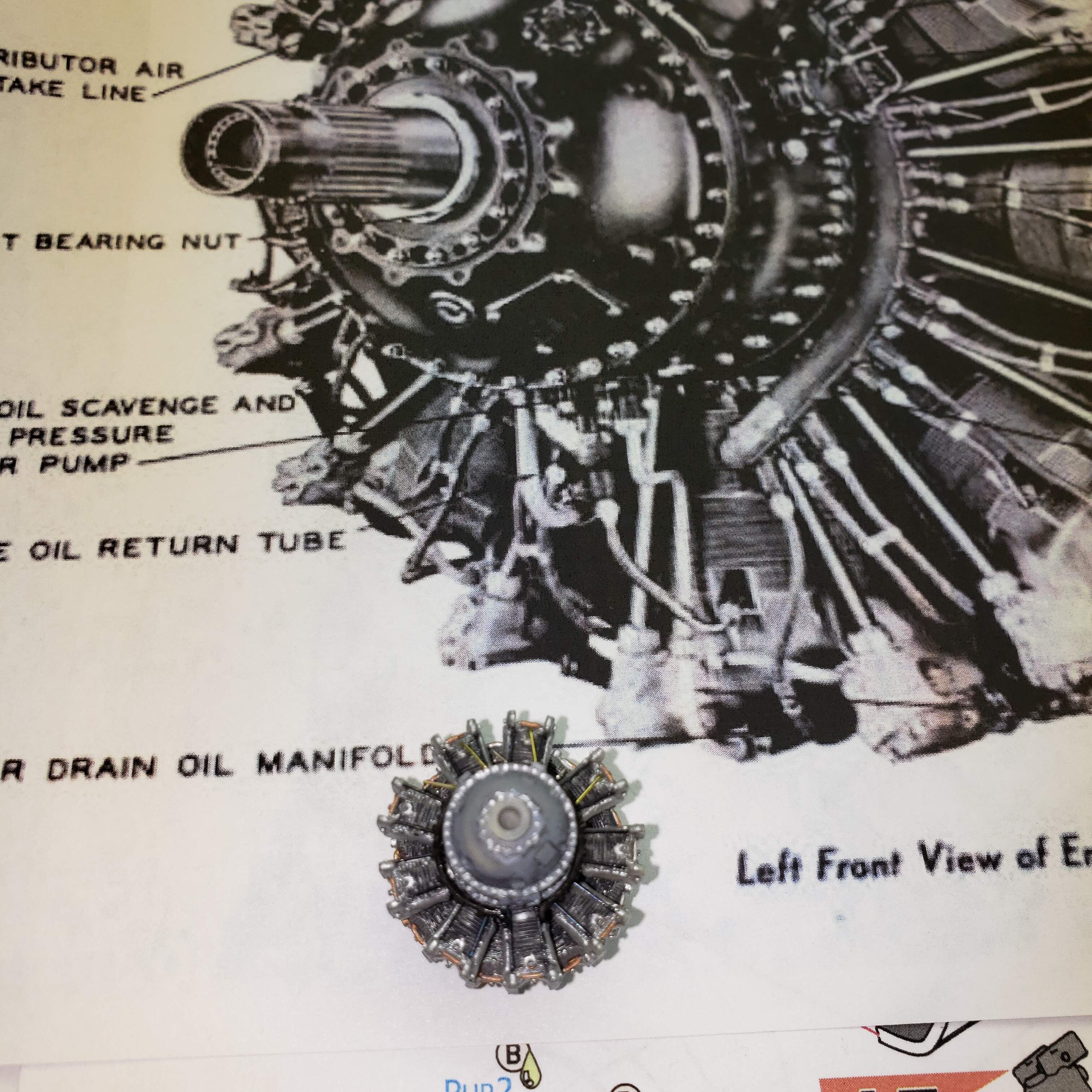
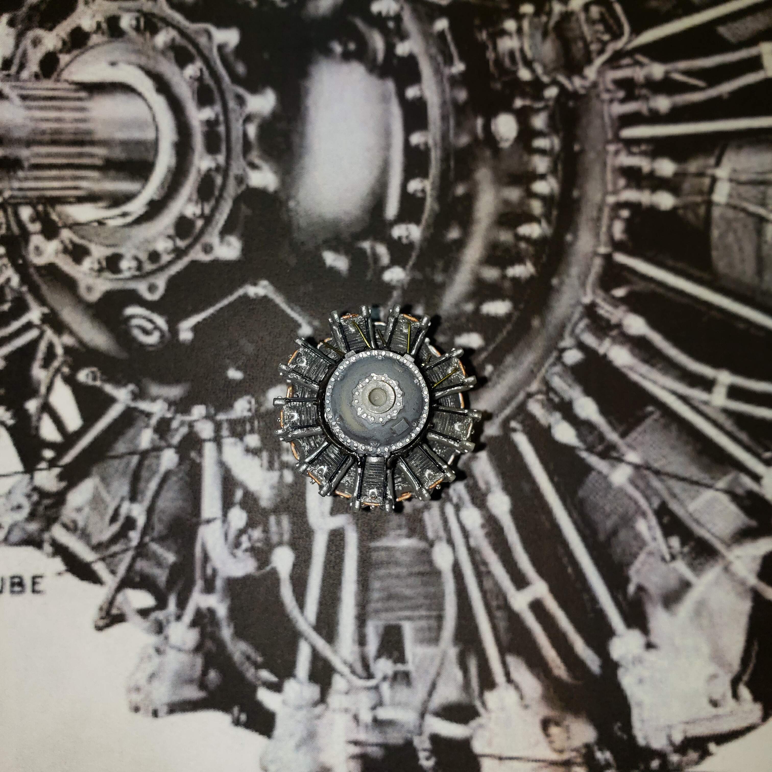
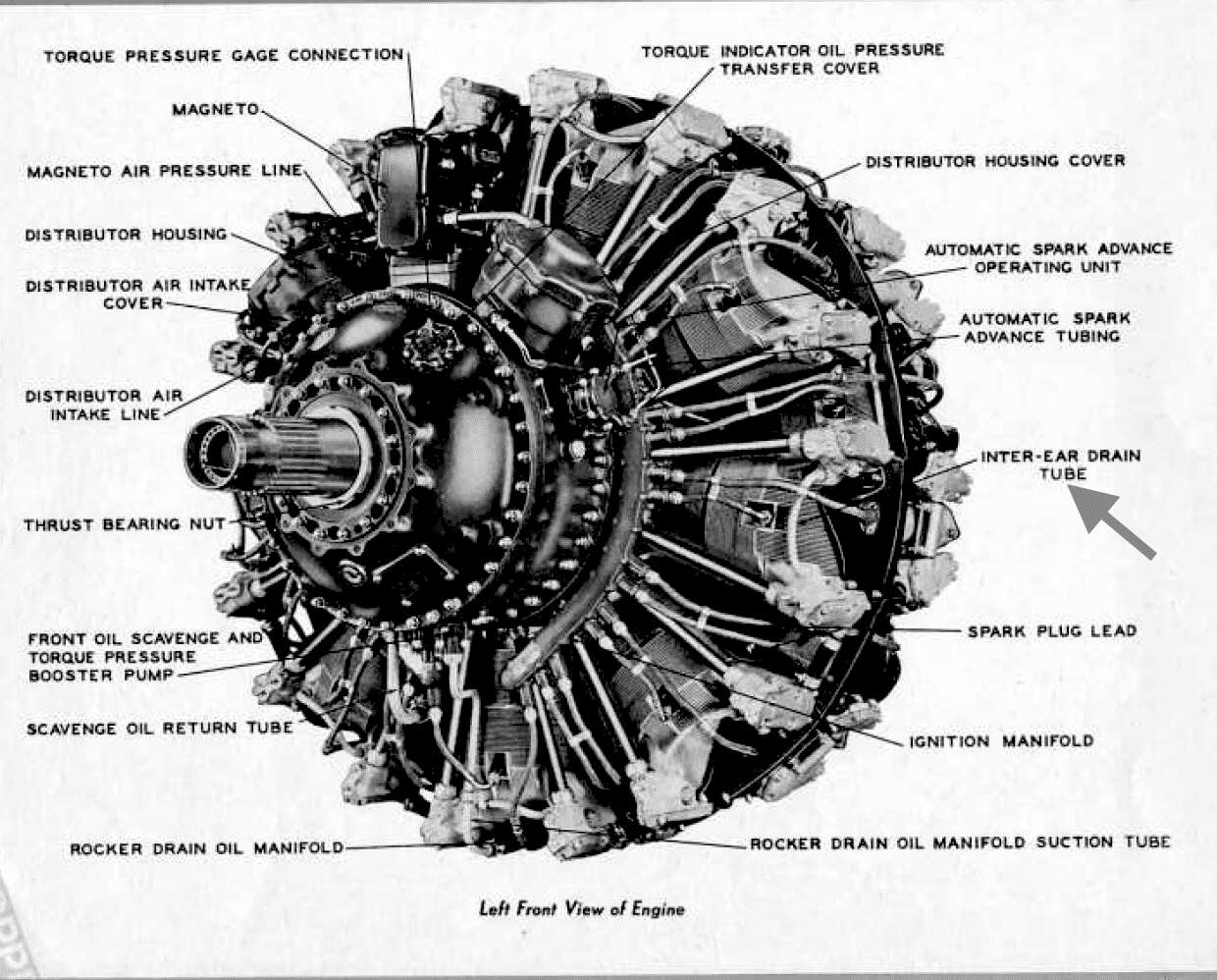
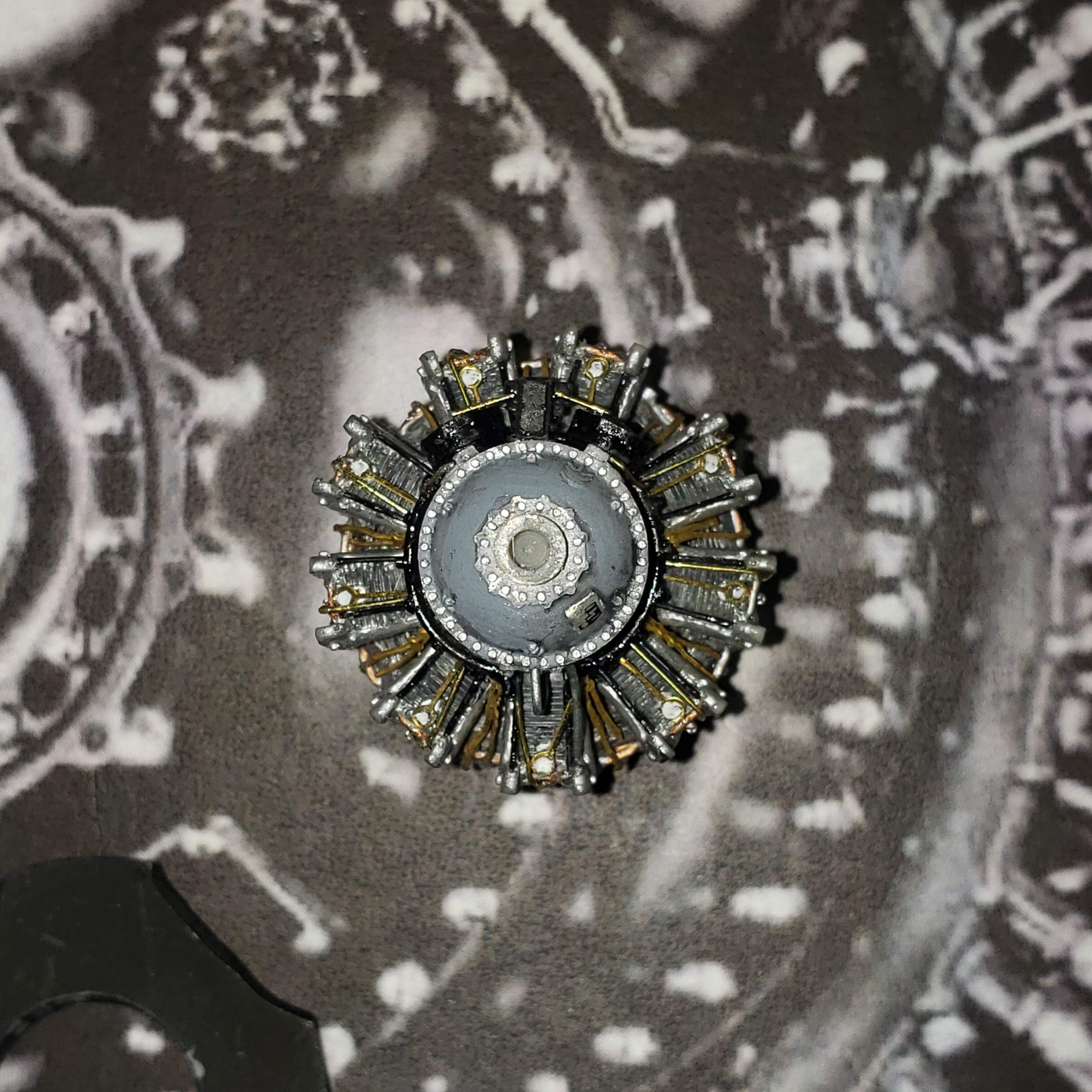
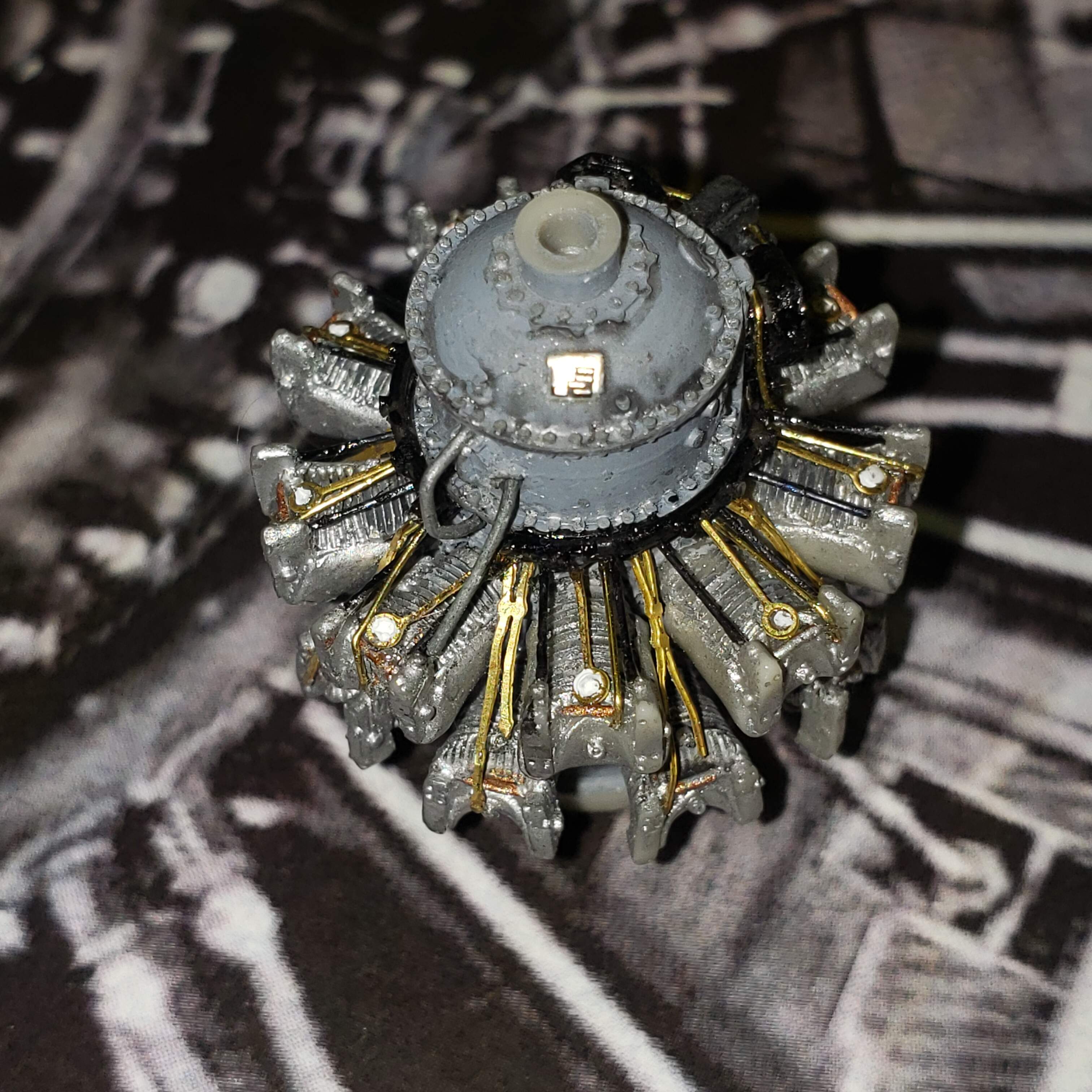
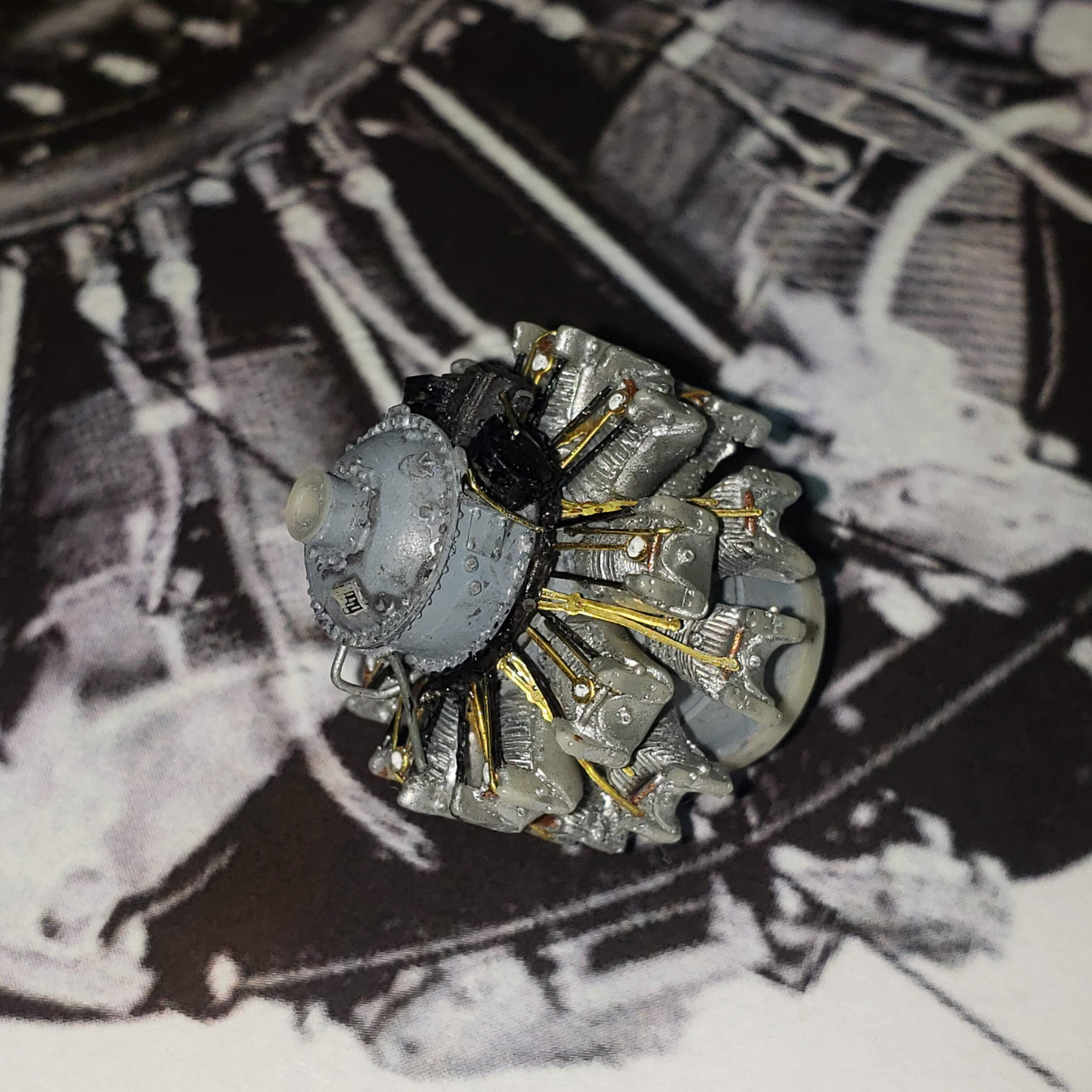
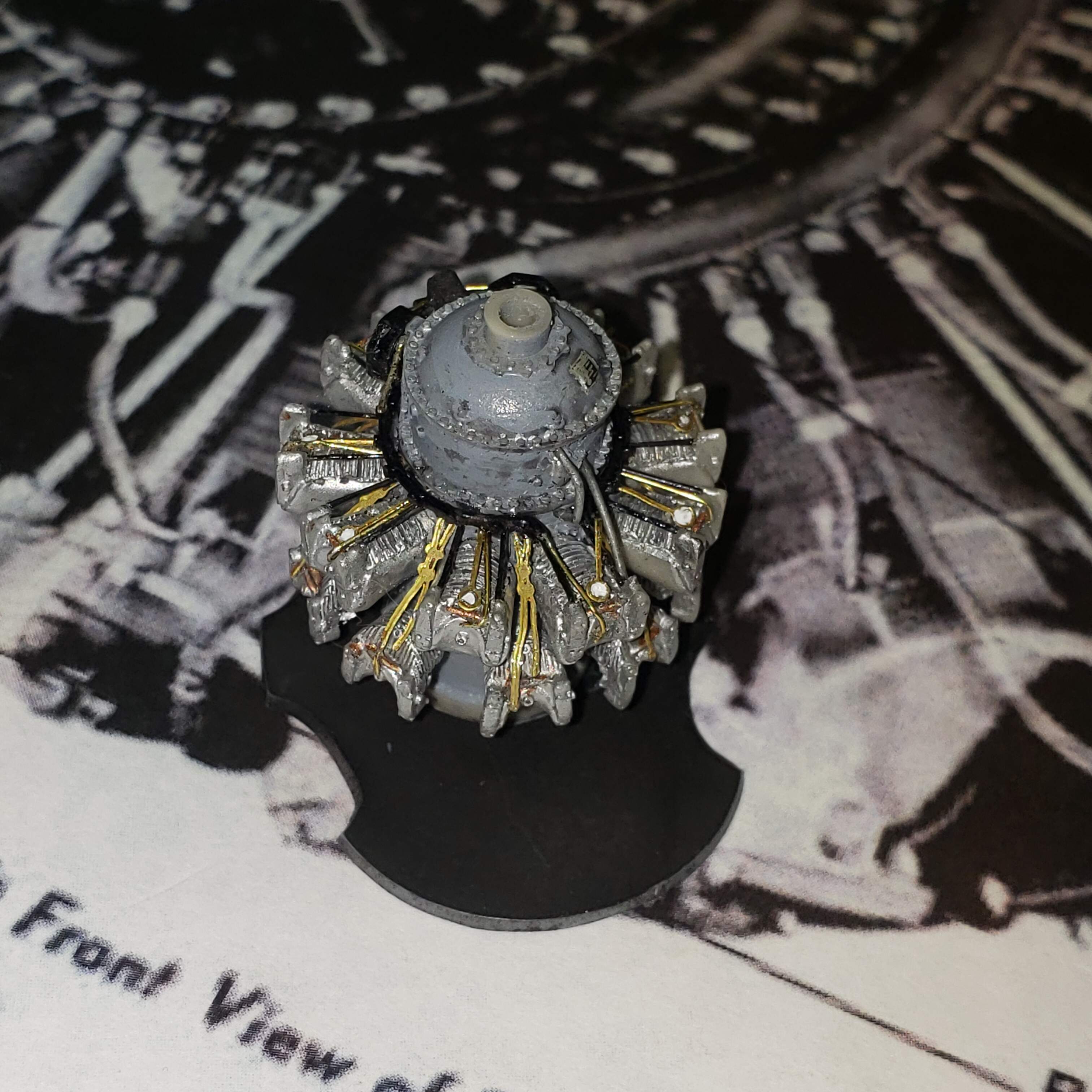
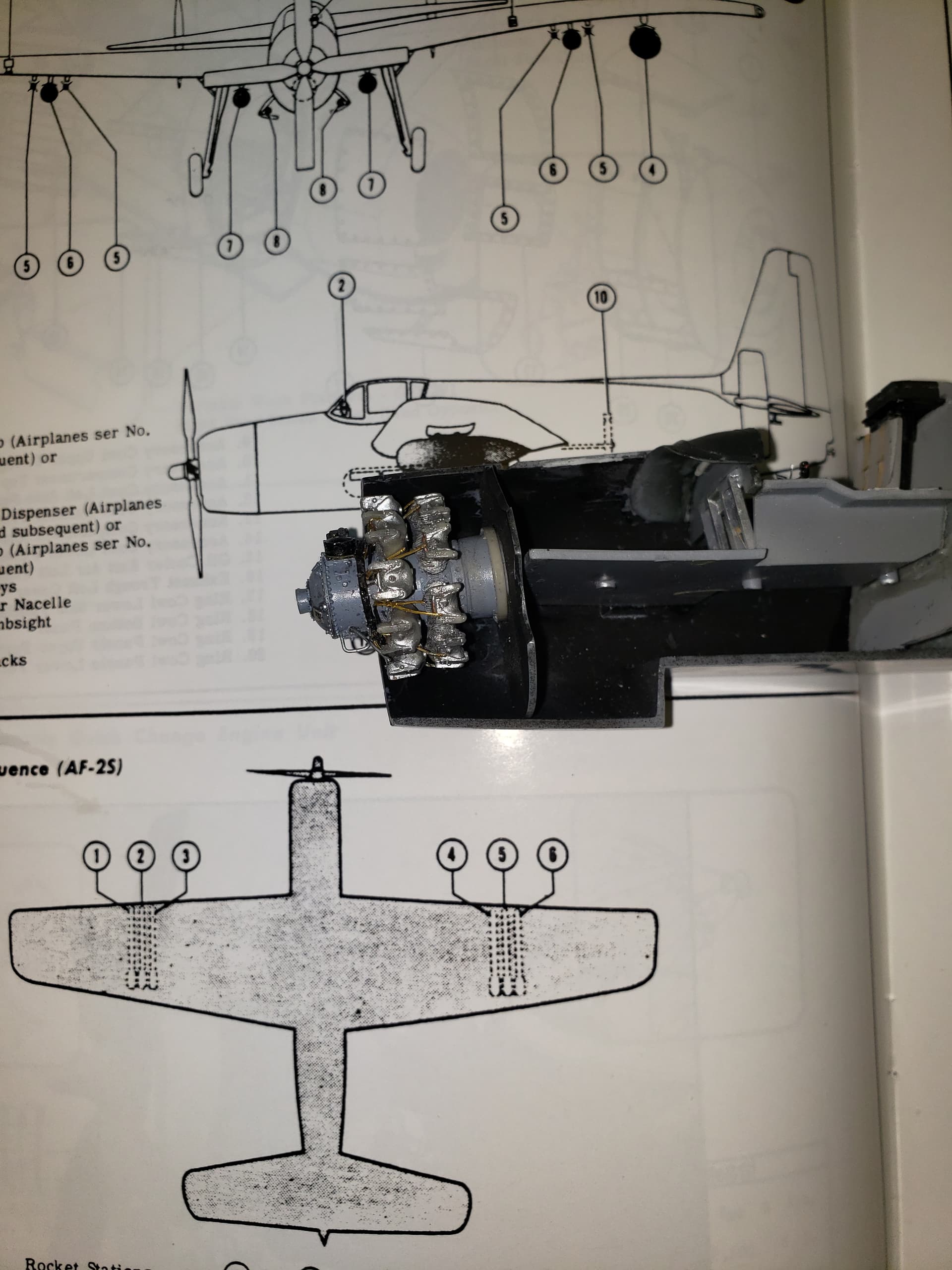
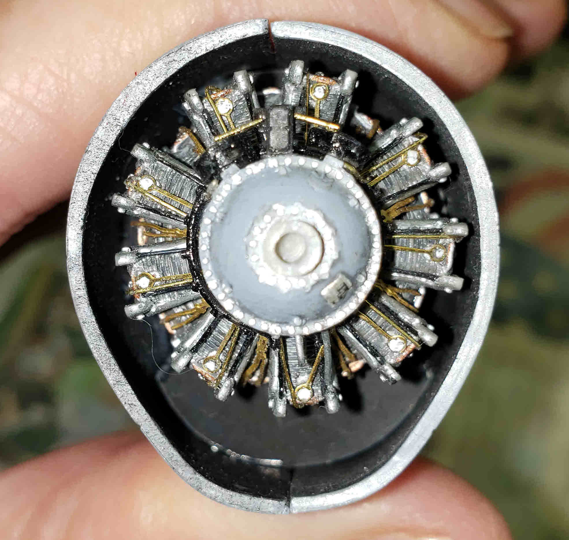
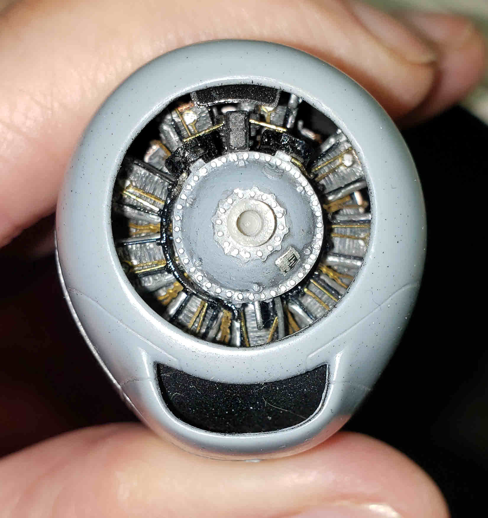
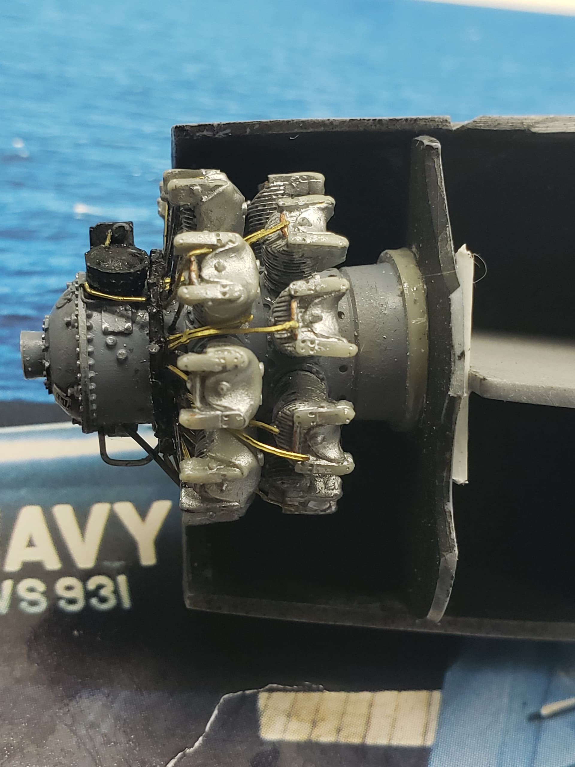
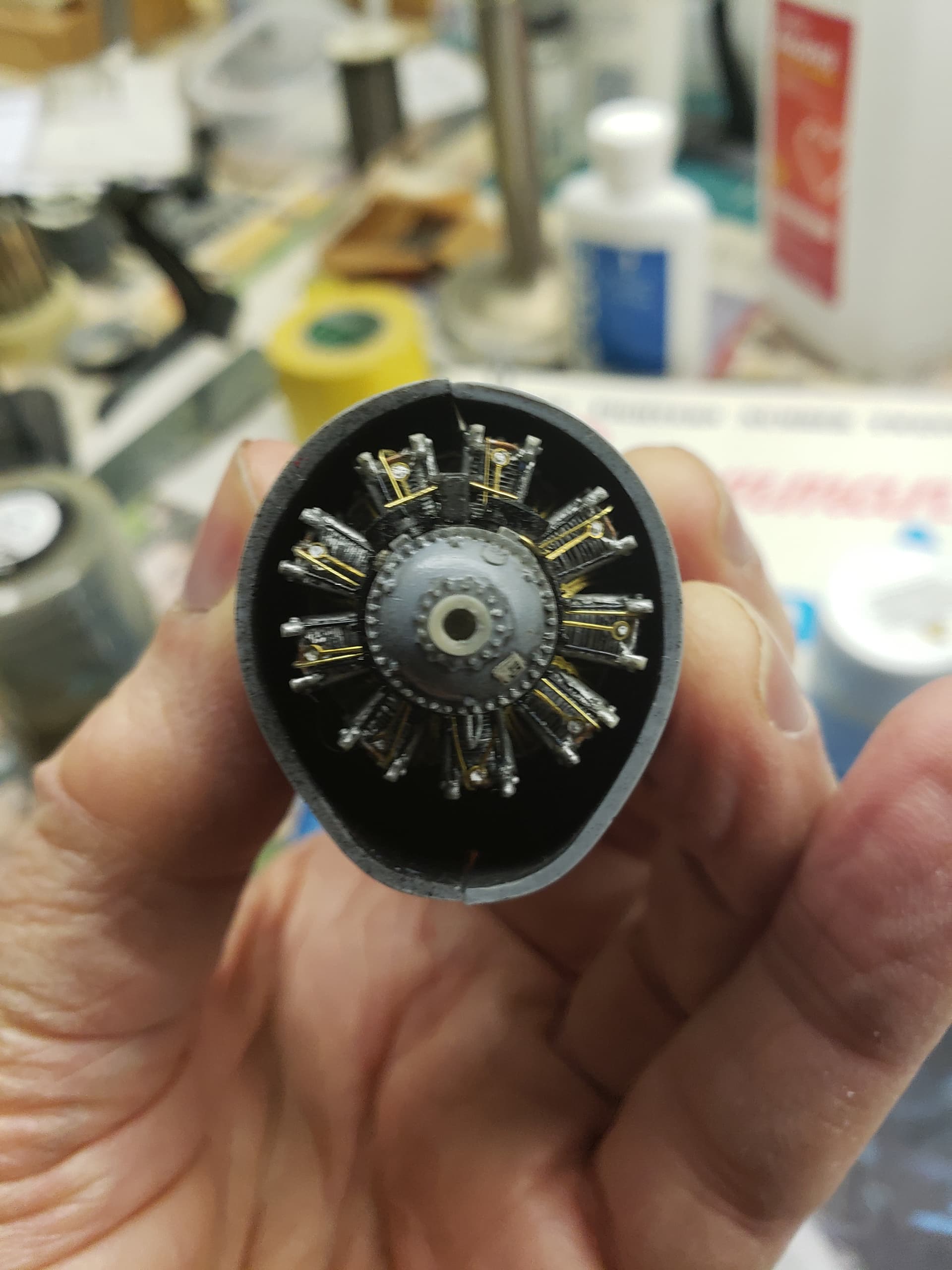
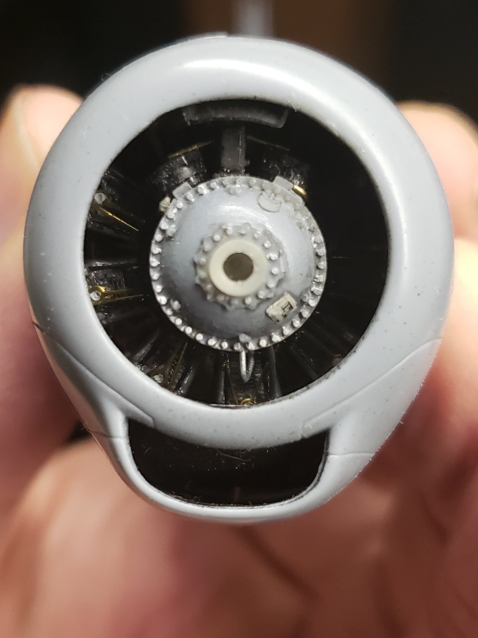
Next is the completion of two rudimentary crew spaces aft, which are barely visible behind small rectangular windows, and installation of a rudimentary firewall, which the instructions do not tell you must be installed at a slight, right angle, since the engine was offset to compensate for the strong torque generated by the aircraft’s Pratt & Whitney R-2800-48W “Double Wasp” radial engine, rated at 2,400 hp.

Stay tuned.

6 Likes

Brian - I am delighted to see you posting your builds again - what a nice surprise ! Count me in .
Cheers Richard

Thank you Richard. It’s about fookin time, I reckon. PS, I still owe you a picture of my build of the Tamiya Birdcage F4U-1. I’ll put that up Tomorrow.

He’s back and better than ever. This looks seriously good Brian and such a cool subject too. Gonna look fantastic on the self!

1 Like

A quick post to show I’m still at it. Seats in the after crew compartments.

The instructions say to paint the floor white to match the bulkheads and fuselage walls, but the mind rebels at the idea of WHITE floors and so I am painting them in a medium interior “aircraft grey” per instructions for other parts of the interior, i.e. the cockpit. It’s really Tamiya grey primer in the can, but it’s “close enough.”

Both compartments were filled with electronic and other equipment, but the sparseness is justified by the fact that the fuselage windows are tiny rectangles, and only an impression of the seats will be visible through the clear plastic, and virtually nothing else. Works for me.

I also did work on the fuselage fit. What a bear!! This is NOT, as I stated before, a shake-n-bake model. FAR from it.

More when I get the bulkheads and fuselage sides painted a “flat white” per the instructions.

2 Likes

THE BARE ESSENTIALS

The after compartments, but one will see virtually nothing through the tiny windows other than the seats through clear styrene.

I still have to install the fuselage windows, do some clean-up of the cockpit, install the tail wheel well, and position and glue in the slightly angled firewall before attempting the delicate task of gluing the fuselage halves together.

3 Likes

So you don’t want to be drawn down the rabbit hole of another multi year interior detailing build ? LOL
Looks good Brian and I’m going to play the broken record again: good to see you building again !
Richard

2 Likes

It was a rabbit hole as large as the Grand Canyon. I’m still going to mess around with “fixing up” some of the diecasts I bought – including continuing the fixer-upper of the Marushin D3A-2 in 1/48 – and some other projects, but it really IS time to return to the “pure” hobby of building one from scratch. And this is a very “The Bridges of Toko-Ri” era subject, which is at the outer end of my modeling interests.

Thanks for watching!

1 Like

BABY STEPS AND A NEEDED CORRECTION

Here’s the tail wheel well

And some work on the firewall area for the engine.

Before gluing the firewall in and gluing the fuselage halves together, I decided I needed to complete the engine and glue it to the firewall, so that I wouldn’t be gluing a complete engine into a deep cowling opening with all kinds of placement problems.

The angled white styrene at the front of the horizontal flooring is intended to provide an angled base for the firewall to be glued in. The engine in the real thing was angled to compensate for the strong torque to the right that the engine generates.

So, what’s wrong with this picture?

In a “What was I thinking?” moment, I angled the styrene so that the engine would also be angled to the right, thus compounding the problem of right engine torque!

My gut told me there was something wrong with this, but my eyes fooled me because I was looking at a line drawing of the aircraft from the bottom rather than the top, thus getting the angle backwards!

You can see this better from the below view of the aircraft in flight.

AF-2S_weapons_bay

How could I have thought that angling an engine to the right would decrease torque to the right!?

These pics also confirm a slight engine placement angle to the left

and possibly a slight downward tilt to the engine as well.

So the next immediate step is to rip out the offending styrene angling the engine to the right and replacing that with the “right” angle.

It’s going to require more study while I build the engine.

But I still have to finish some corrections to the cockpit. That’s next.

5 Likes

COCKPIT “CLEANUP”

OK, one of the things I wanted to deal with in the cockpit was those two brass-colored openings in the boxes to the right of the pilot seat.

It was worth looking at a photo from the Ginter Guardian book.

Pardon the flash reflection on the forward box with the angled front, but you can see the real aircraft had a hinged cover to this that was missing from the kit brass, and that the rear one remained open.

So I made a cover out of styrene sheet, painted it black and installed it over the front opening. For the rear box I made and placed in the opening a white, grey-edged, sandwiched rectangle that’s supposed to simulate an aircraft technical manual. (As good a guess as any, I suppose.)

I had to re-glue the seat in and install a couple of other small pieces and consider the cockpit basically done now. It’s far from perfect, but I am happy enough with the view that will appear under the large canopy (just don’t look too closely, please!) to move on to building the engine. That should be more enjoyable.

3 Likes

ENGINE START!

To begin with, I was quite wrong about the tilt angle of the engine against the firewall, and the Special Hobby design to reflect it. The only other full-blown build blog of this model I know of is by Tom Cleaver over at Modeling Madness. It’s worth a look. I now believe him when he writes there:

**Special Hobby has done their research with these kits. They have designed in the 3-degree right offset and 3-degree down angle of the engine correctly; the engine is the now-standard resin with separate crankcase and cylinders.

I take him at his word on this after further research of my own. More on this later.

The aircraft came equipped with a Pratt & Whitney R-2800-48W “Double Wasp” radial engine, 2,400 hp (1,790 kW) and here is a picture of a close cousin, an R2800-32W I found online.

unnamed (2)

The -48W was a "C-Series engine, which was:

a complete redesign of the R-2800. Some of the main changes were: forged rather than cast cylinders, allowing an increased compression ratio (from 6.65:1 to 6.75:1); a redesigned crankshaft; a single piece (rather than split) crankcase center section; a two-section nose casing, incorporating hydraulically operated torque-monitoring equipment and an automatic vacuum-operated spark-advance unit.

Here’s a color picture of an unknown C-series varient, which gives a better idea of the color and details.

However, colors vary.

There are some brass/bronze highlights near the top of the cylinder heads I might copy from this one.

unnamed (3)

Time will tell.

Here’s my start. Nothing fancy,

At least I’m building again.

3 Likes

ENGINE DETAILS

Herewith a few pictures of my engine detailing efforts. In this first one note that the instructions are wrong. The open end of the ignition harness is at the bottom, not the top of the engine.

Although it should be grey per the photos, I elected to paint the ignition harness black per the instructions for the sake of variety. Colors varied on these things, and when I saw a Guardian at the Naval Aviation Museum in Pensacola years back, the darkness of the engine stuck out in my mind. (That’s my excuse and I’m sticking to it.)

The cylinder heads and barrels were weathered with Flory dark weathering. The pushrods are naturally black wire, and I am using unpainted brass wire for the ignition wires. There are no less than 36 brass wires to shape and attach. Ugh! :dizzy_face:

The drawing, which I found online, will be helpful in showing what goes where, and guide me in laying a few additional pipes at the bottom once the ignition wires are done,

Then will come touch-up and positioning the engine at the proper downward/to-the-right angle in the firewall.

2 Likes

ENGINE COMPLETED – “JUST RIGHT”

It’s been a while but tonight I completed the R-2800-43W radial engine for the Guardian.

I’m going to let the pictures do the talking, except to say that nothing I do is “perfect,” but “I’m happy with this” and I don’t mind some slight accuracy offsets that “fool the eye,” which I why 1/48 is my Goldilocks scale – Just right.

I think it has just enough extra detail and “dirt” to give it a lifelike look and to be the eye-catcher I want it to be looking straight on into the cowling,

In the last shot, you see the engine sitting on the black firewall. The engine will have to be carefully positioned to show the proper downward and to-the-right angling to counteract torque, per the aircraft design.

There are a couple of rectangular fuselage windows to glue in and mask in the after fuselage, and then comes the next major step – gluing the fuselage halves together, and ensuring I can insert the arresting gear in through the tail at a later time–or now if necessary.

Later!

6 Likes

The Double wasp looks brilliant Brian, gone are the days of painting engines just black. Great research too
tim :smiley:

2 Likes

FINAL STEPS BEFORE GLUING THE FUSELAGE TOGETHER – BETTER LATE THAN NEVER

Well, clearly I’ve experienced an inspirational lapse after finishing the engine and posting about it on July 8. So, it is something of an achievement that I have restarted this.

These are not the best pictures but they do show “progress.”

There were two parts left to install before actually attempting to glue the fuselage halves together – installing the arrestor hook and the engine.

Here’s my installation of the arrestor hook.

Not exactly elegant, but after doing some research I elected for red and white stripes on the hook and steel on the tip.

Next comes the aggravating job of trying to position the engine to get the proper downward and port offset angle as on the real aircraft.

Contrary to what another build reviewer has said, this is going to have to be done by “seaman’s eye” since the engineering of this part of the kit is less than instructive. The engine doesn’t just drop in at the right angle, at all.

Gluing the halves together is going to be a pain in the neck as well, since the fit is rough on this limited run kit. It will be one section at a time and a rather tedious and exacting process.

After that, I will (again) fix up some details in the cockpit such as the seat headrest and the AC outlets on the instrument panel coaming as well as at the rear of the flat instrument and control array to the right of the pilot seat and near the rear bulkhead. These fell off and I have to scratch build triangular-shaped pieces that look like vents.

I plan to glue the engine in tonight.

EDIT: Upon further examination, the hook painting needs to be cleaned up, and it needs to be repositioned slightly. (The devil is in the details, and “I can do better than this.”)

4 Likes

Glad to see you back at it Brian .
Cheers- RT

1 Like

Very pleased to see your build continuing Brian :smiley:

1 Like

MOAR! FINAL STEPS BEFORE GLUING THE FUSELAGE TOGETHER

Going back to front, I sanded down the arrestor hook, re-primed it, and sprayed it white. (Yes, in real life it’s white, not gray.)

It’s a toss-up to me whether the dark stripes on the hook are in the picture are red or black, but the lighter tint tilts me in favor of red. Plus, it will add some color.

This time I didn’t rush the masking.

But how well it turns out after I spray the red remains to be seen. That’s a task for tomorrow.

Now, the engine.

After a lot of fiddling, this is the down & port-side position I chose for it.

Notice the cracks on the skin of the fingers in the background. (I’m using really old tools for this work).

Here’s a more aesthetic view with the cowling on.

I do think it conveys the “What’s wrong with this picture? (even if it’s right) look” that the real thing has, but time (and the prop) will tell. There is a risk that if you look at pics of the real aircraft you won’t see the changed positioning at all, so here I decided to give a whole new meaning to the term “scale effect.”

Finally, I am semi-psyched to continue. I want to make a decent, clean-looking display model then move on to more exotic topics, leaving the other “Killer” variant for later. It will be nice to have at least one of these Korean War monsters in the display case.

5 Likes

Looks like you are on a roll Brian - keep the momentum going!

2 Likes

NOSE TO TAIL

After gluing in the engine last time I found myself unhappy with the angle that it was canted to the right, looking forward. I decided to give some photographs of this bird another look.

Here is what I consulted.

This is the Guardian at the Pima Air Museum. One sees the definite tilt to the right.

Next, I took a closer look at the Guardian preserved at the National Museum of Naval Aviation in Pensacola.

af-2s-guardian-002

I don’t think there’s any doubt that there is a slight but subtle tilt to the right (and bottom) in these views. I like the last photo best.

So, how to fix my solidly glued-in engine? Rip it out and replace it? No. That’s going backward.

So, I resorted to something simple. I inserted a styrene piece of bar, which you can see below between the “firewall” and the “floor” of the cockpit.

Crude but effective.

Subtle enough for you? It works for me. I’m not gonna mess with this again.

Now onto the tail, where I said that I was unhappy with the paint job on the arrestor hook.

Here it is repainted and fitted into the fuselage at a lower angle that conforms better to pictures I’ve seen.

And this is what it will look like with fuselage halves joined.

I’m okay with this too. So I have no further excuses for not doing the fuselage halves together.

That I plan to do this weekend.

5 Likes