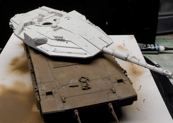
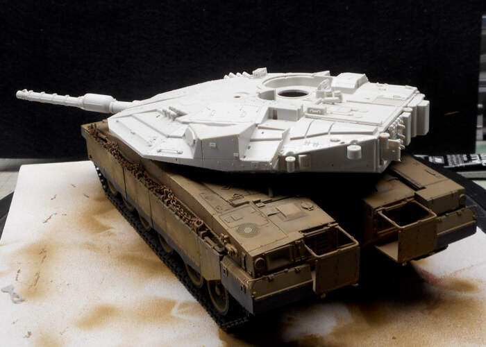
The bottom part is complete, started the first sessions of painting
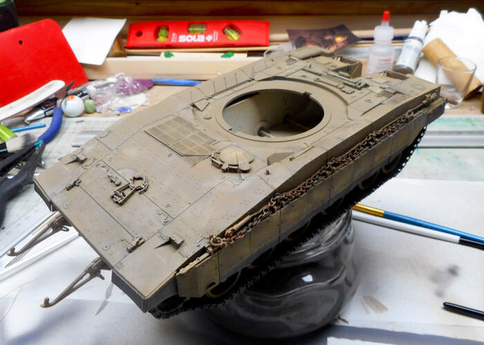
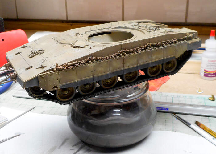
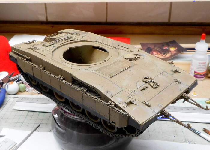
Still a way to go
looking good!!! ![]()
![]()
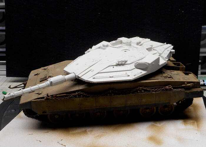
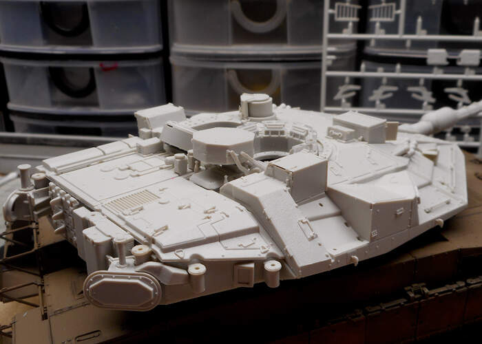
Jan, is that chain on the hull side the right size ? What is it used for ? It looks massive ??
Thanks Nikos for clearing that up. I take it then if they use chains, they don’t have what I would call a normal recovery rope like on a Chally or M1 ?
Is there a reason behind it ? I would of thought (and I’m sure I was taught it ) that a chain would have more fail points than metal recovery ropes and is it just one length of chain per tank ?
I think there is also mounting points for a tow cable on the left side- usually the cable is mounted behind the chain or the chain is sometimes left off. Then sometimes both chain and cable are mounted plus another chain at the front! @ReluctantRenegade may be able to explain why this is.
So what were the deflectors for on early Mk1s then?
To allow proper air circulation in the engine compartment. The Mk.1 and 2 had air-cooled engines with two large fans sitting on top.
Sure, but I think I better open a new thread as I don’t want to hijack this one.
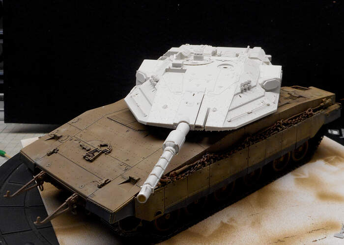
I LOVE the Meng Mk-IV LIC EXCEPT for thT ball & chain nightmare. Might work well in the real world but is certainly a PITA at 1/35th! I ended up just doing the ‘outside half’ due to so many diving off my desk into the great unknown (also where socks & tupperware lids go I suspect). Thought about getting the trophy system but in the end $$ won out.
My Meng Merkava IV didnt have individual ball and chains they didnt need assembling,they were consolidated see step #29 parts E77 E 81 E82 unless they handled it differently in your kit but this one was pretty simple,no balls rolling off the bench into infinity.
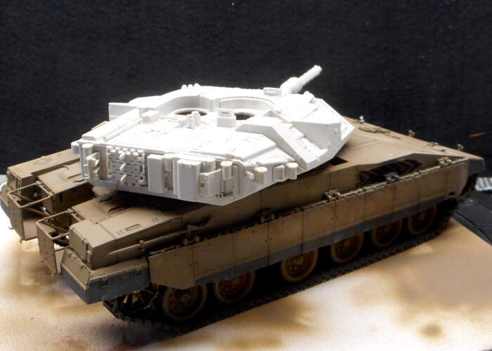
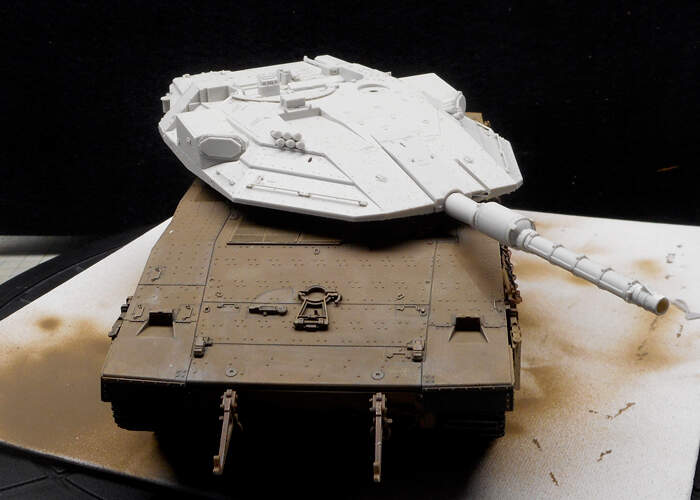
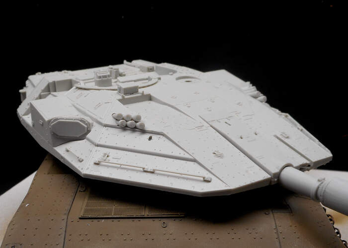
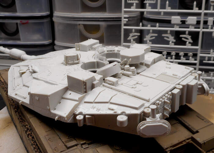
Still working true the building plan, feels like putting thousand very small parts together ![]()
Don’t know about other brands, this one is very detail t with filigree parts.
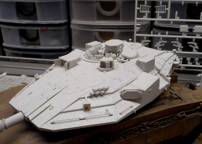
Still some page to do
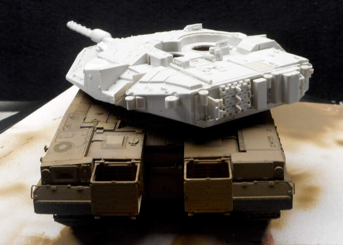
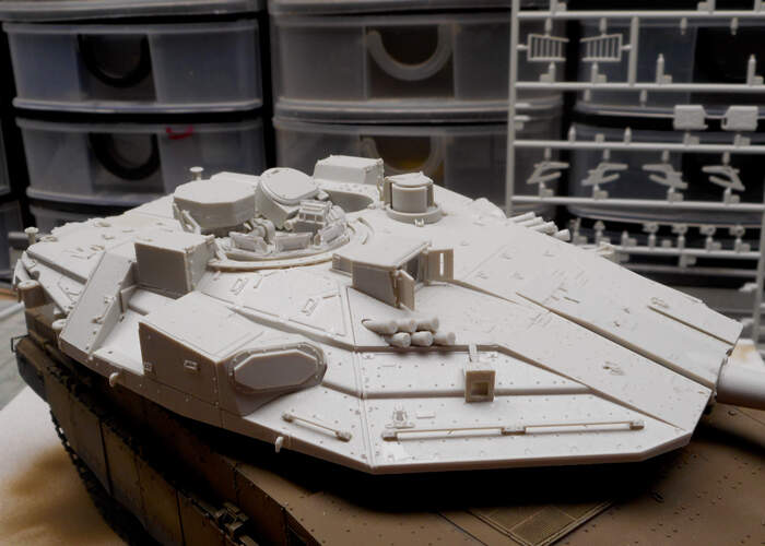
Certainly looks like it goes together well Jan
looking good, I like the gun, looks good detailwise
I Think once complete, it will be a from the detail a good model.
But the parts are real small, I think every hinge and buckle are separate to glue one
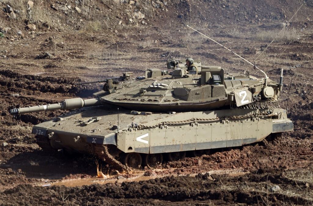
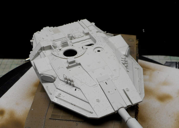
Boy that turret sure looks futuristic. It could easily pass as a part of a spaceship in a sci-fi movie.
Thanks, so this leads to another daft question.
So both exhausts are now directed out via the slats and also the air that has been cooling the engine? Or, are more modern Mks water cooled?
Not a daft question at all. Late Mk.1s had both their exhaust redirected via the large opening on the right side of the hull. Now, I don’t know why they did that, but I suspect the original exhausts were generating way too much heat and could benefit from some cooling. The Mk.2 had the exact same setup.
If you look at the photo of the engine I’ve posted above, you can see that the exhaust of the left-side cylinder-block was redirected between the cooling fans producing the middle stain on the deflectors, whilst the right-side exhaust was bent upwards 180 degree (that part is missing from the engine on the photo) exiting perpendicular to the the other exhaust, producing the strain forward on the deflectors.
Mk.3s and 4s have liquid-cooled engines with a large radiator sitting on top of the engine. I’m not familiar with their exhaust arrangements, but based on what Nikos said, the Mk.3 probably has a similar setup of the earlier marks, while the Mk.4 most likely has one tailpipe for both cylinder blocks leaving a single strain more or less in the middle of the deflectors.
That turret looks fantastic