Good day fellow modelers,
Yesterday I started working on the Tamiya SD. Kfz. 9 Famo.
I decided to work on this project one step at a time as it is a difficult and challenging kit to build.
Yesterday I have assembled the engine and I must say it is an interesting part or subject of the build.
I was thinking of posting pictures of every step in the building project.
And I also thought that this was a perfect opportunity to get tips and other good stuff from my project as I’m working on it.
I’m fairly confident that my building and constructing quality and skills are good to build a decent quality model kit.
Please forgive when I need more information or explanation on a certain technique or topic. Because I don’t know the technique or something.
I’m also hesitant on doing and trying new things as I’m mostly practical minded. And that I have to see the purpose of a certain technique or topic.
I’m going to try to update this topic as I’m making progress on the project.
But please forgive if I’m needing help doing this.
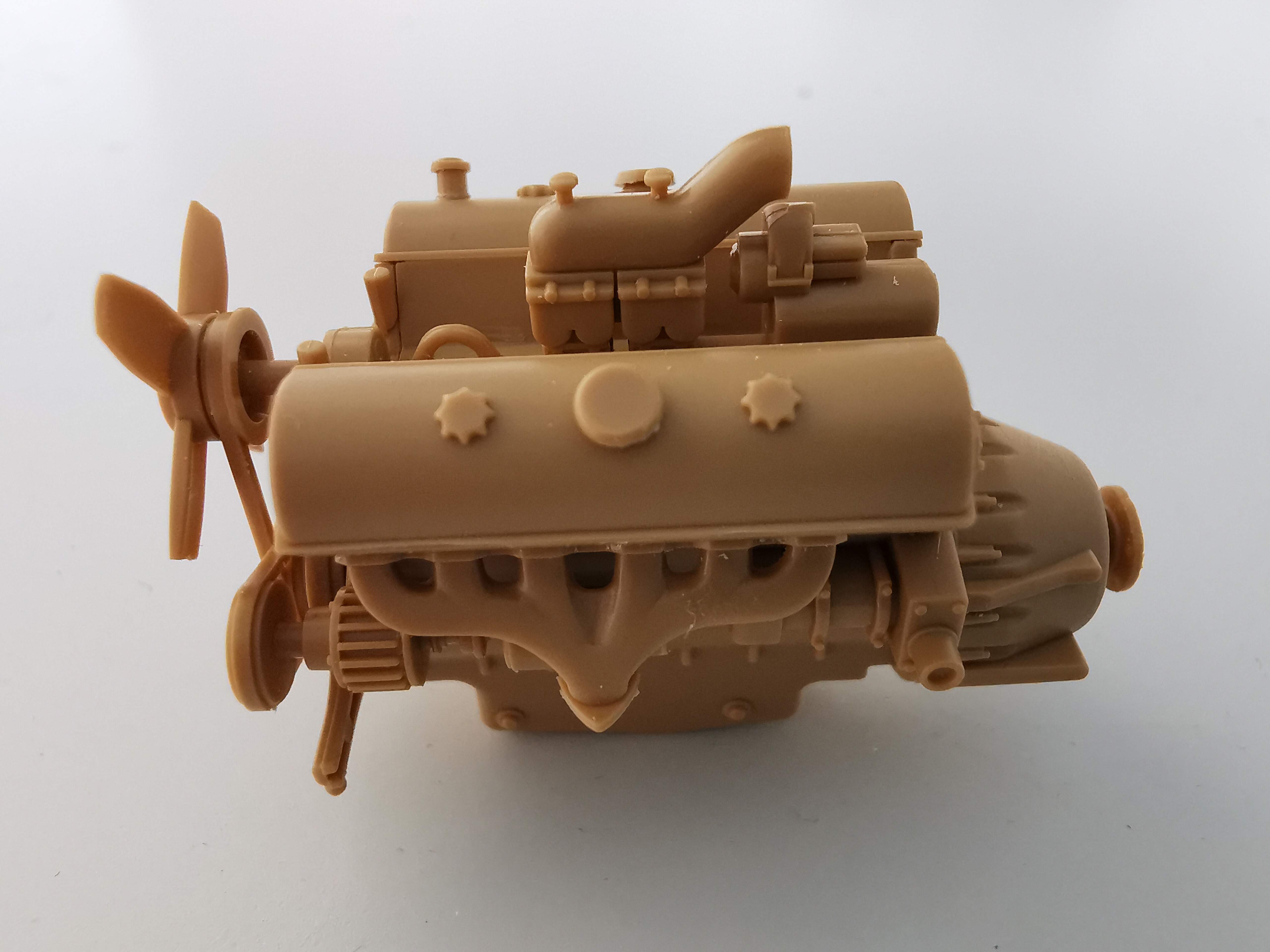
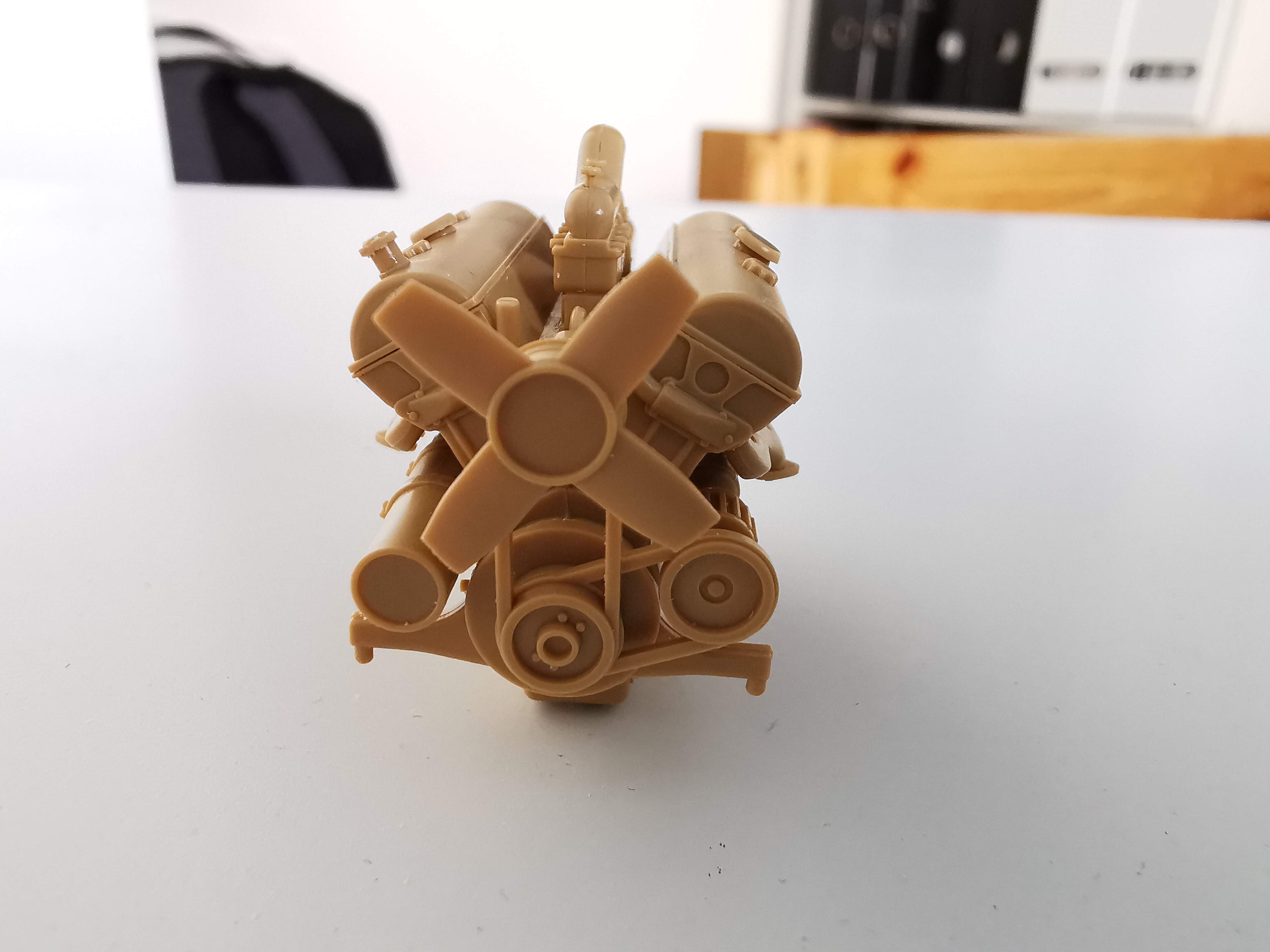
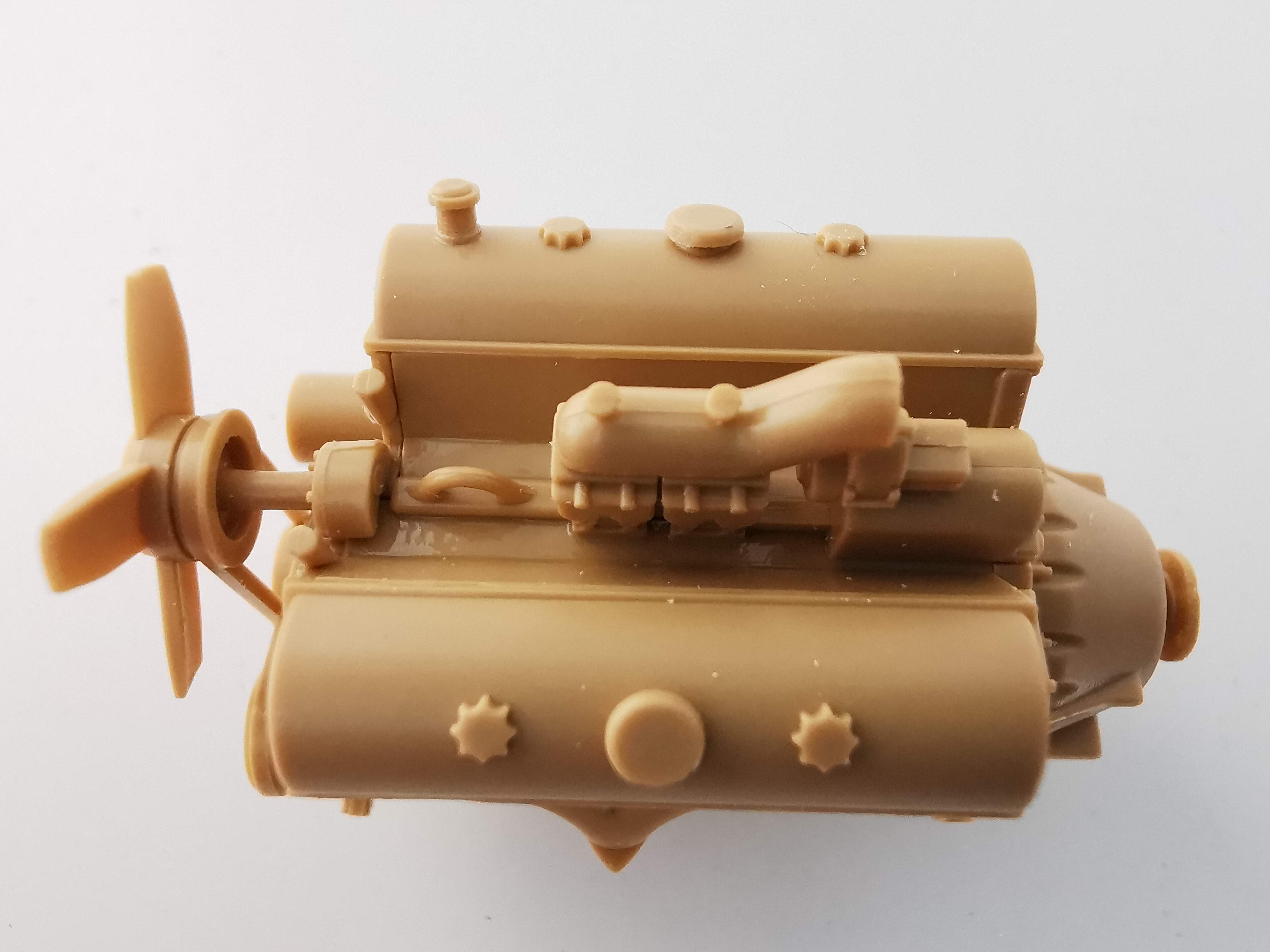
Enough words, here are the first pictures:
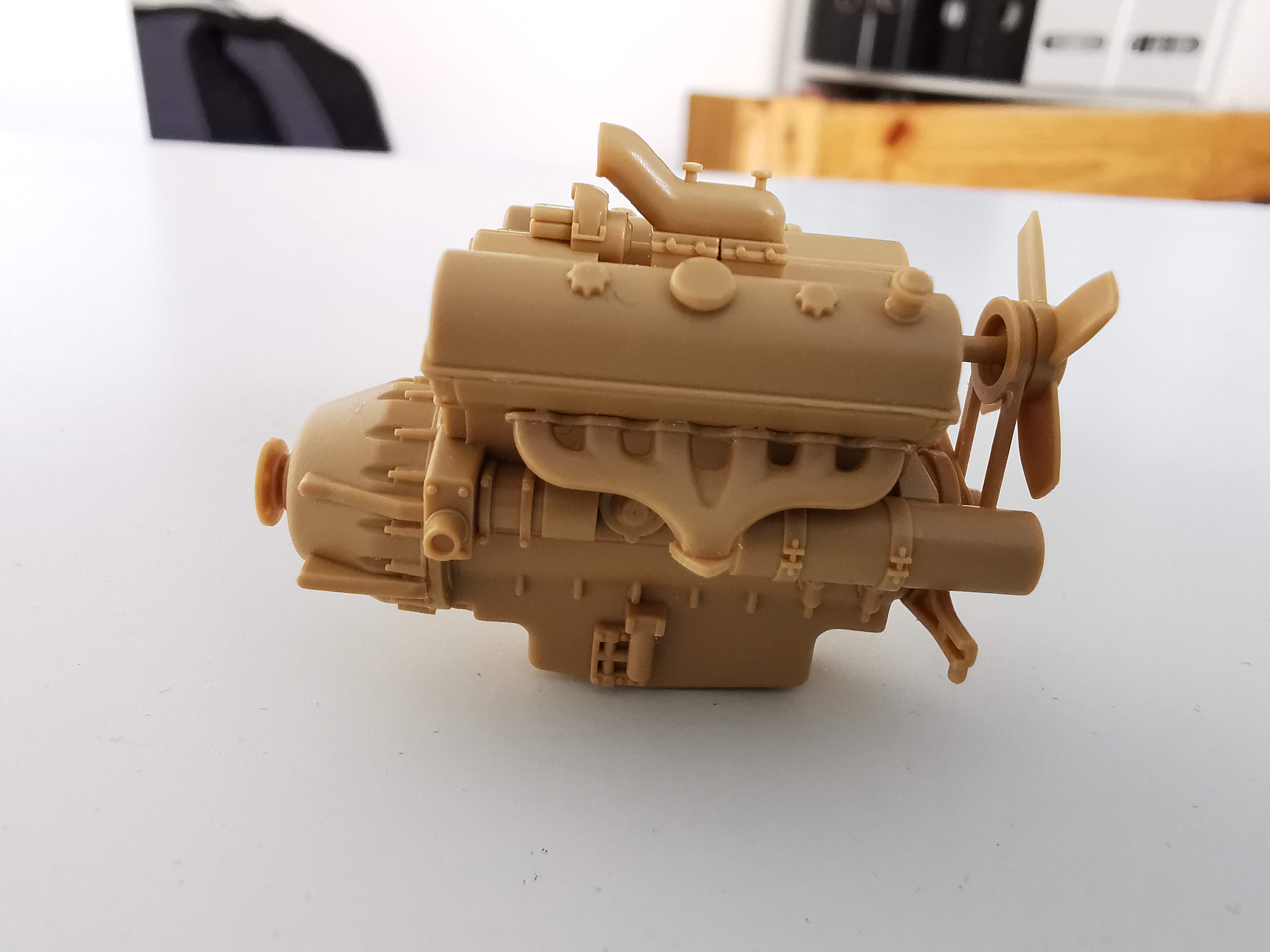
Engine assembled. Maybach HL108 if I’m not mistaken.
I have done the filing work on the carburoteur. And the seam is removed somewhat I believe.
But when I was working on this particular part, I came to the conclusion that I didn’t really have the tools to do this kind of work properly. The best I got was files from Tamiya and a knife from Revell which is rather old. And even that didn’t work that well. I think I need to do some more research online before purchasing some better tools do this kind of job better.
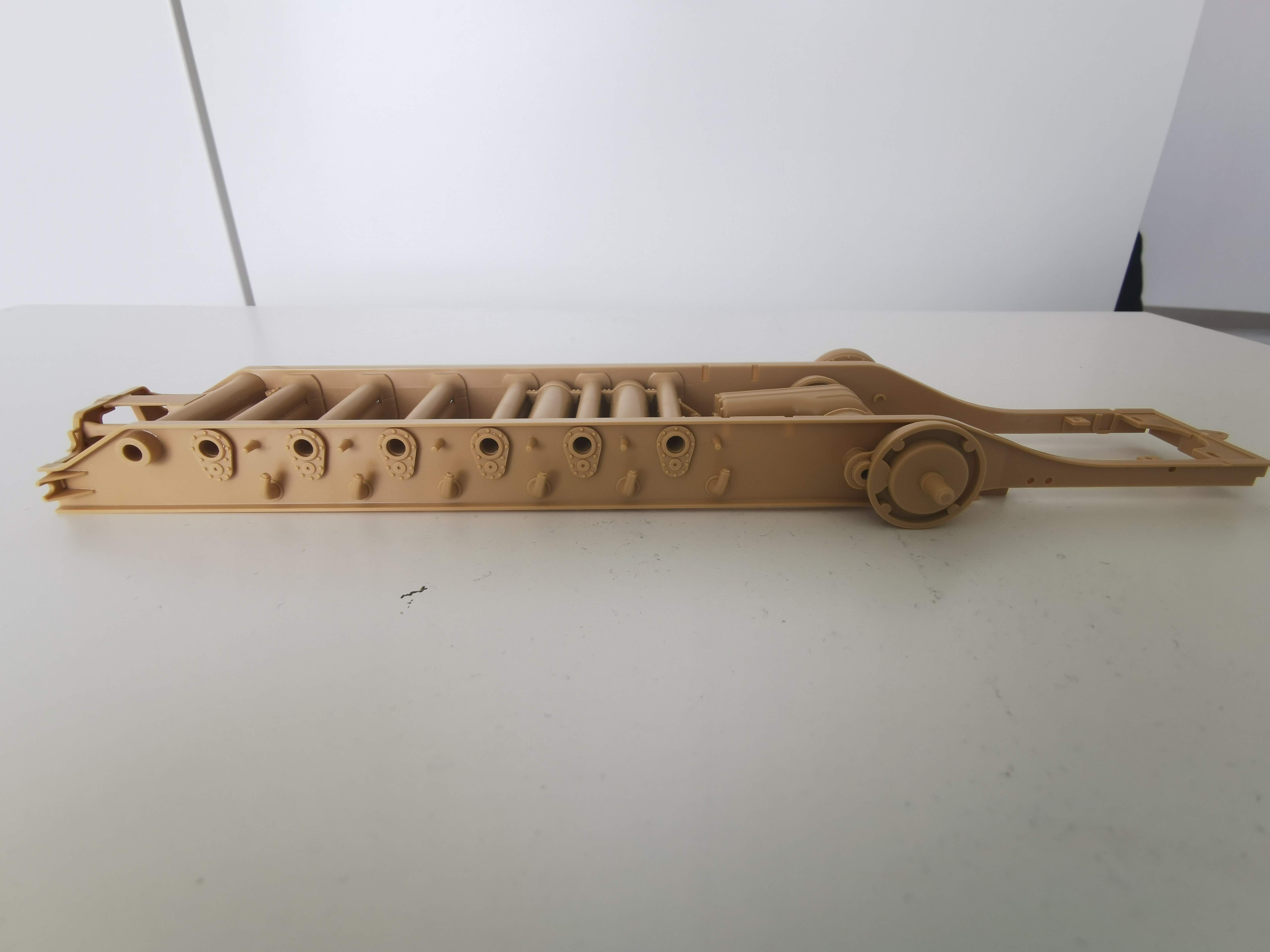
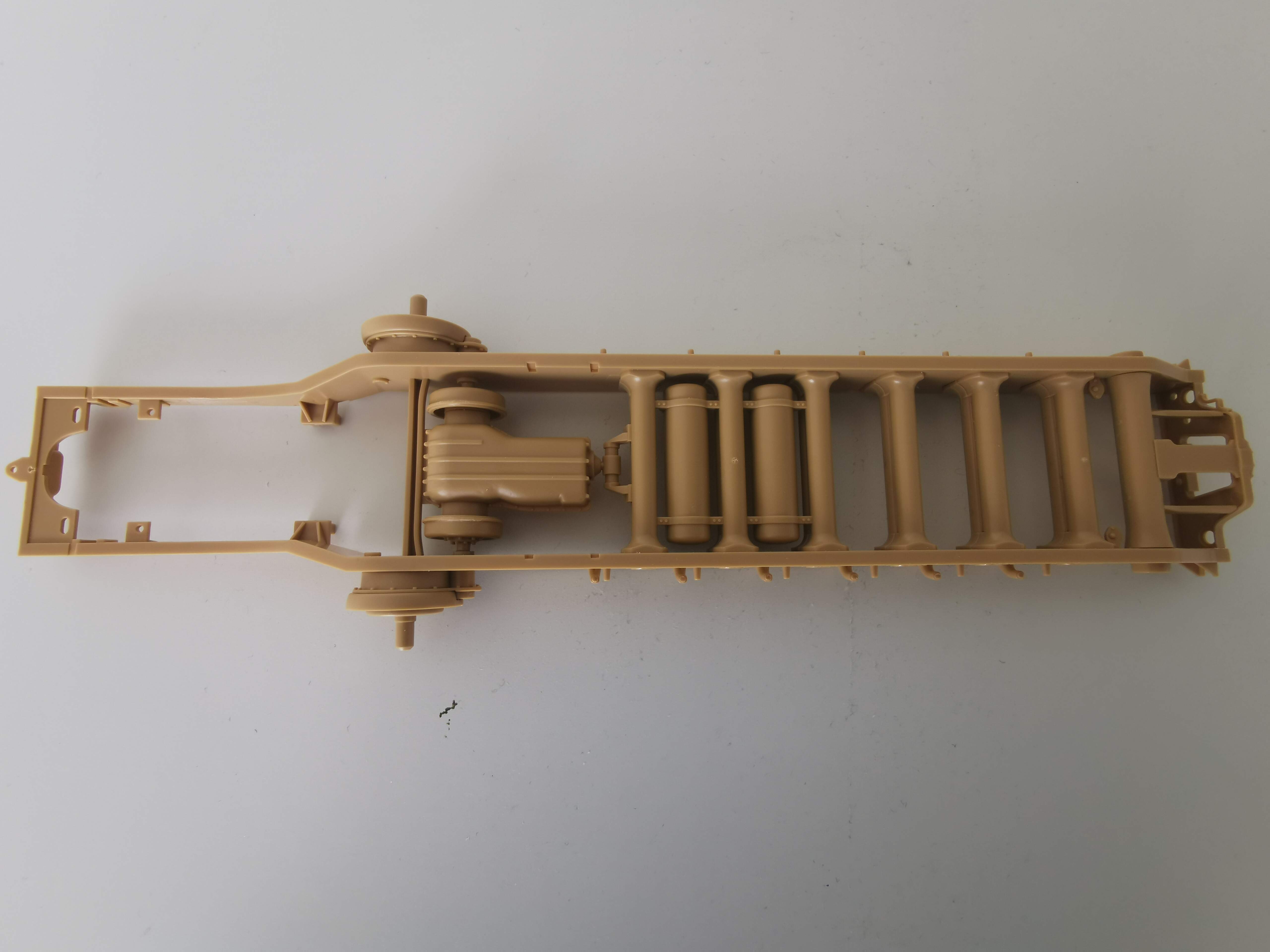
Yesterday I’ve worked on step two of the project according to the building instructions.
The process took a lot of time but I think the result turned out nicely.
I was founding it hard to determine if the seamlines had to be taken care of.
Because I didn’t exactly know if these were visible later on in the building process.
So I did choose to not do to much about them.
I did some filing with some sanding sticks I got from Revell.
But I just found it hard to determine, maybe with more experience and feedback I get more feel for it.
Or some tips and rules?
9 Likes
Feel free to post and ask, we are all constantly learning.
Seems that you still have a couple of seams to clean, if you plan to leave the hood open. In that case, note that you should add cables, pipes and details… Usually engines in models are quite basic.
Tell me about how I would do the cleaning part. Because, I have tried it sometimes. But I found it quite difficult to do. Maybe I don’t have the tools to do it?
And what about adding details? Would I need to buy them aftermarket or something?
Thanks for replying
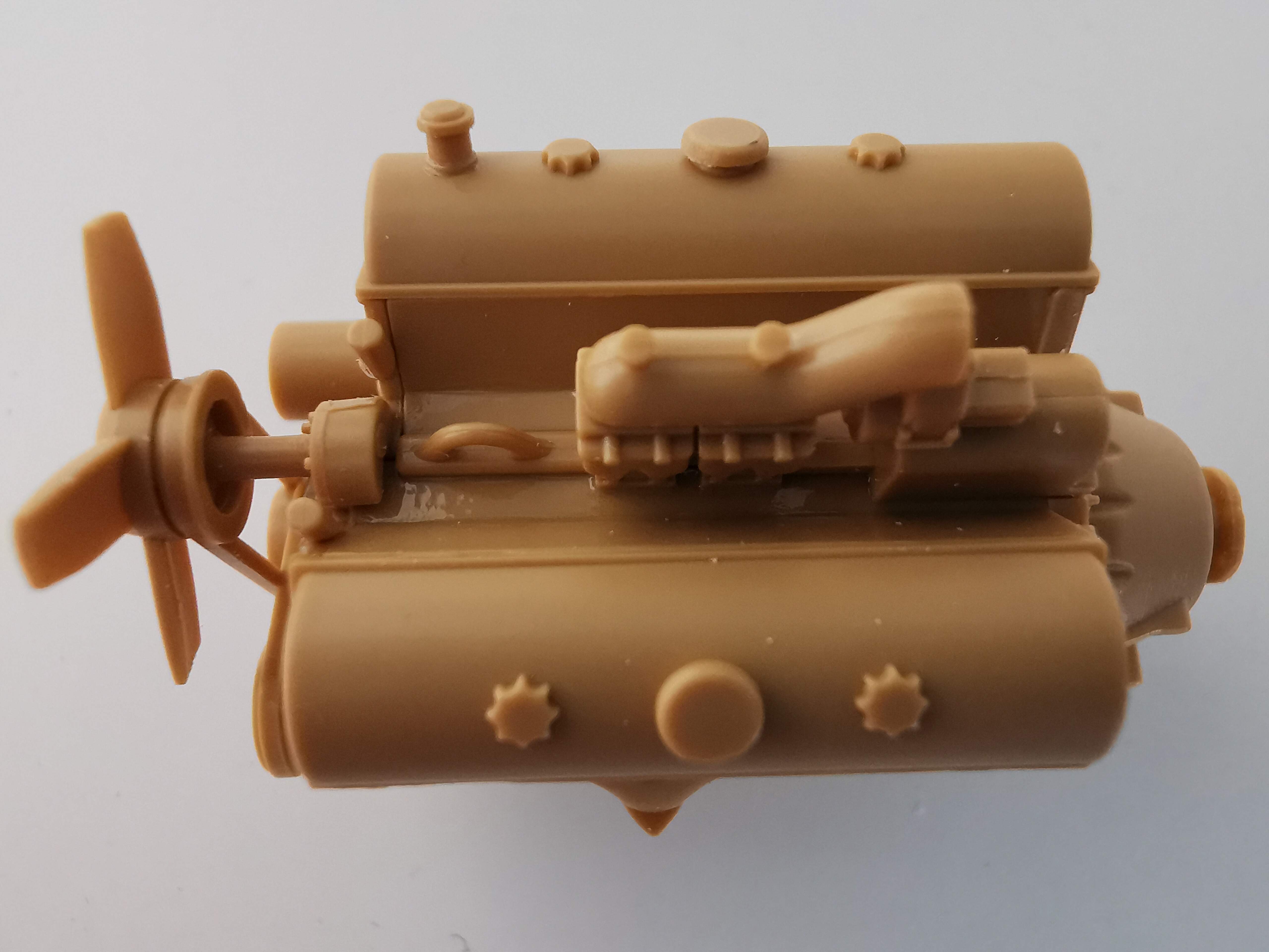
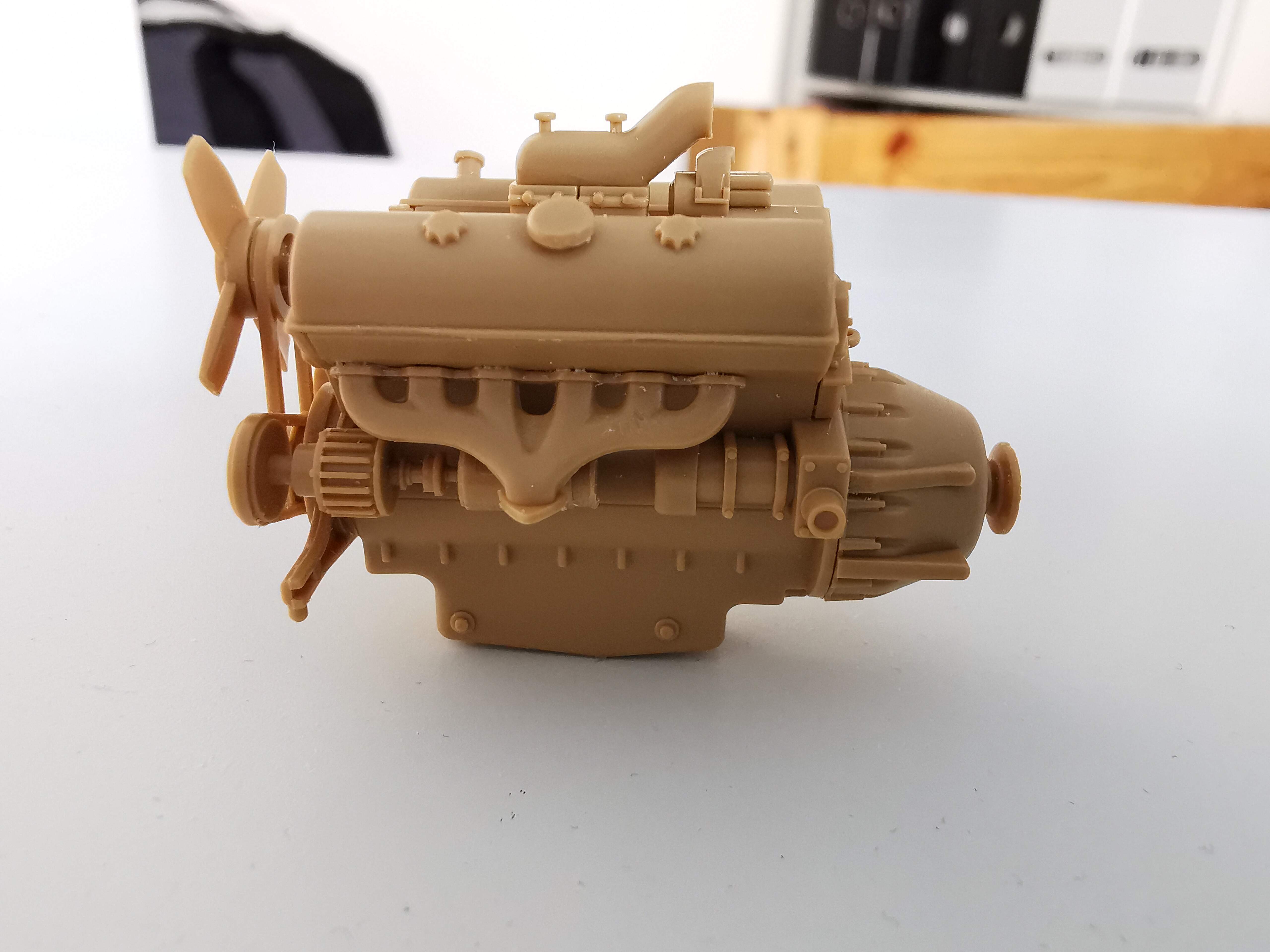
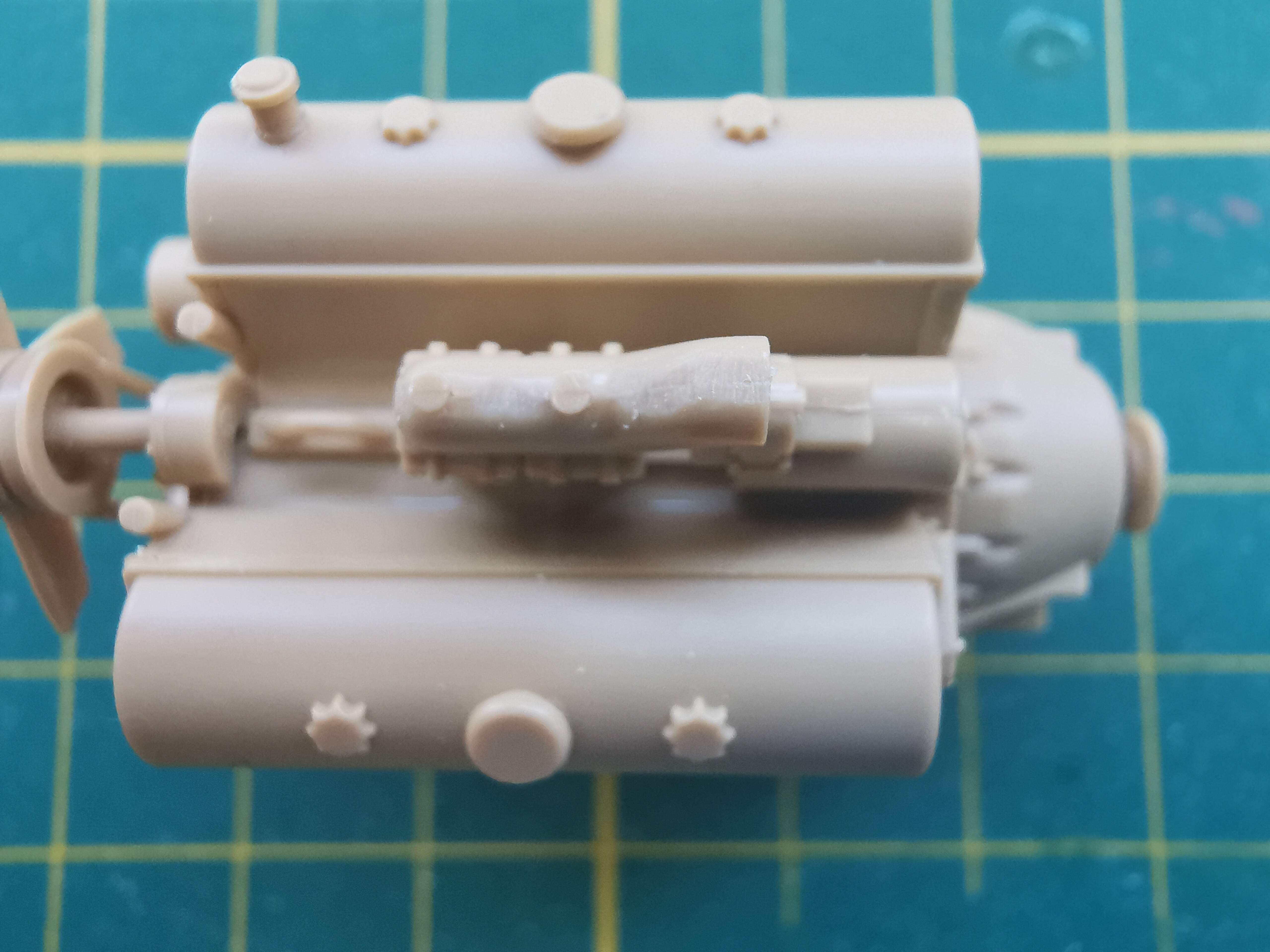
This seam should not be here:

You can remove it with a small file, or sandpaper, or scrapping with the edge of a blade (do not try to cut it!). Work slowly because the part is round and you may leave it flat if overdone.
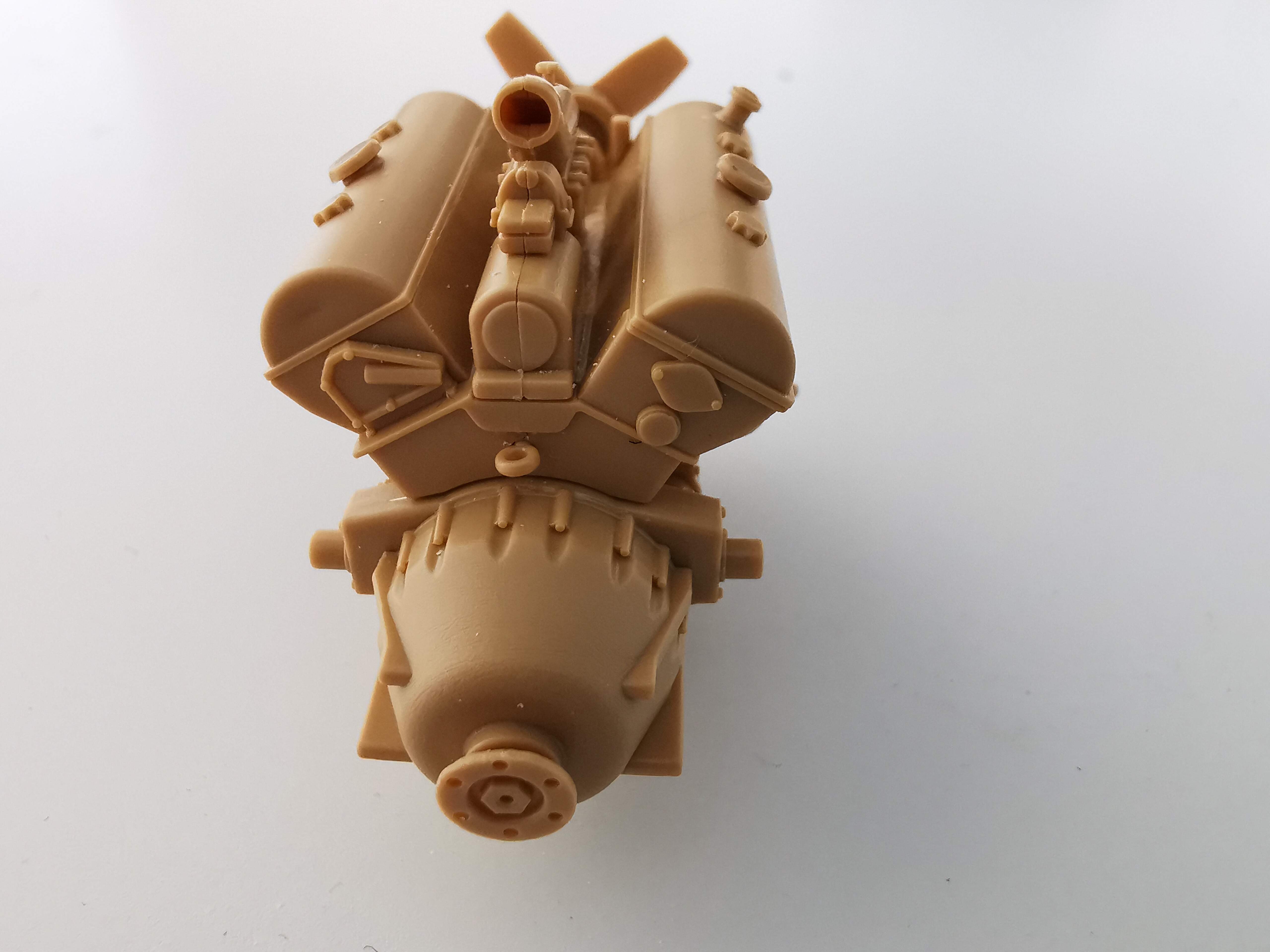
Here you have to fill the gap:

Use some putty and carefully sand flat.
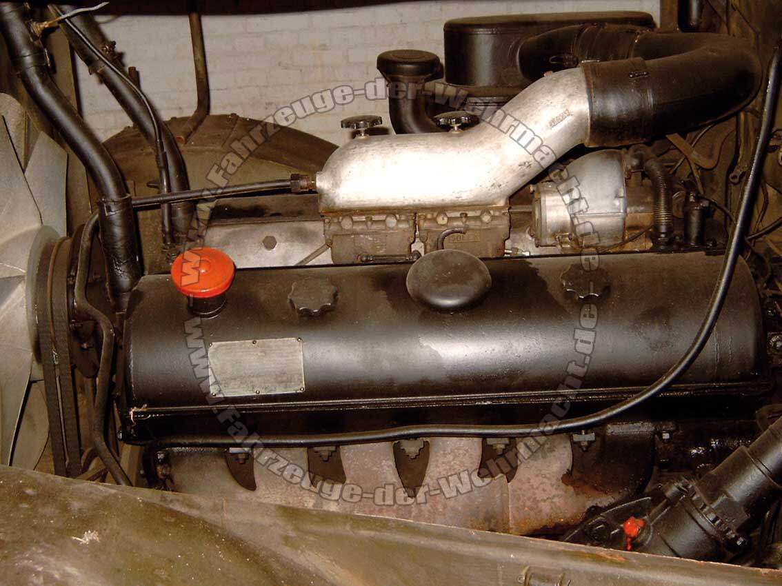
As for detailing, look here:
(there are more images at Maybach Motoren - Fahrzeuge-der-Wehrmacht.de (fahrzeuge-der-wehrmacht.de))
If you intend to show the engine, you should add the pipes and details using wire, plastic, etc. Use your imagination 
7 Likes
The two black knobs appear wider and sit a bit higher atop the silver part in the real engine. I only mention this because you seem very detail oriented.
I like to shave raised seams lightly with the edge of a very sharp knife (X-acto or scalpel type).
Tilt the working edge of the blade away from the direction you are moving the blade.
1 Like
That’s what I tried to say but you have explained it much better 
2 Likes
I don’t have putty to fill gaps. I don’t know yet how to do it. But I remember I have seen an article on scalemates.com on how to do it. So I read that article for that.
Regarding the smoothening of the Seam from the carburetor. I will be trying that. And I will be showing new pictures when I have done this job.
And regarding the detailing. I think regarding that I will just close of the engine by putting the panels in closed position when I get to that step.
Because I’m thinking it is a little bit to hard for me to do that.
Thanks for the feedback.
1 Like
Yes I’m caring a lot about detailing.
That’s what I did with mine 
In any case, sooner or later you will need putty to fill gaps. I like Tamiya grey, put with a spatula and sand smooth -sandpaper from hardware stores is ok, just get the finer ones, I have 400, 800, 1200 and 2500 grits.
1 Like
Thank you so far for the tips and tricks so far.
Anytime I taught kids about models, I would tell them to build like the real thing. Another words, would there be a big 'ol line down the top and bottle middle of a real airplane? Is there a big 'ol seam around mom and dad’s car tires? What about that seam down the middle of a gun barrel of a tank? Those shock absorbers got a line down the middle. Plant the seed, you will begin to see the unnatural about most models. Most of all…have fun!!
If you can’t afford to buy modeling mediums for filling gaps, the next best thing is baking soda and super glue. Primitive but effective. Place the baking soda into the gap, the squeeze enough super glue from one end of your gap…then watch the capillary affect take place. Sand down as required. Repeat if the gap takes more filling. Using this process however requires the use of primer when you get ready to paint so the super glue does not bleed through your finish. Use mom’s emory board for her fingernails to sand it down. Household products are all around you…just have to see them.
1 Like
I think I can afford to buy the putty, but not now.
Because, I’m buying my model stuff online and I need to make large orders to avoid shipping costs.
So that is what I’m waiting on now.
To make a large order of all the stuff I need for my modeling.
And than put these things on the list as well for the next project.
I must thank you as well for the reminder to have fun.
And I’m totally agreeing to that.
But I’m also willing to improve with every project I do.
To get higher quality builds, get to know new techniques.
Get some ‘innovation’ going into my hobby that maybe is rusted in place for quite some time now.
And with that in mind this is one of the best places to do that.
Thanks for the replying.
1 Like
Needle files (not the expensive diamond type) for trimming mould seams, injection points and other “faults” from the parts.
Gaps are sometimes/often caused by parts not being flat due to needing release angles to be able to get the part out of the mold. Mold seams can also cause problems
Dry fit first and check if the gaps can be eliminated by filing/sanding the mating surfaces flat.
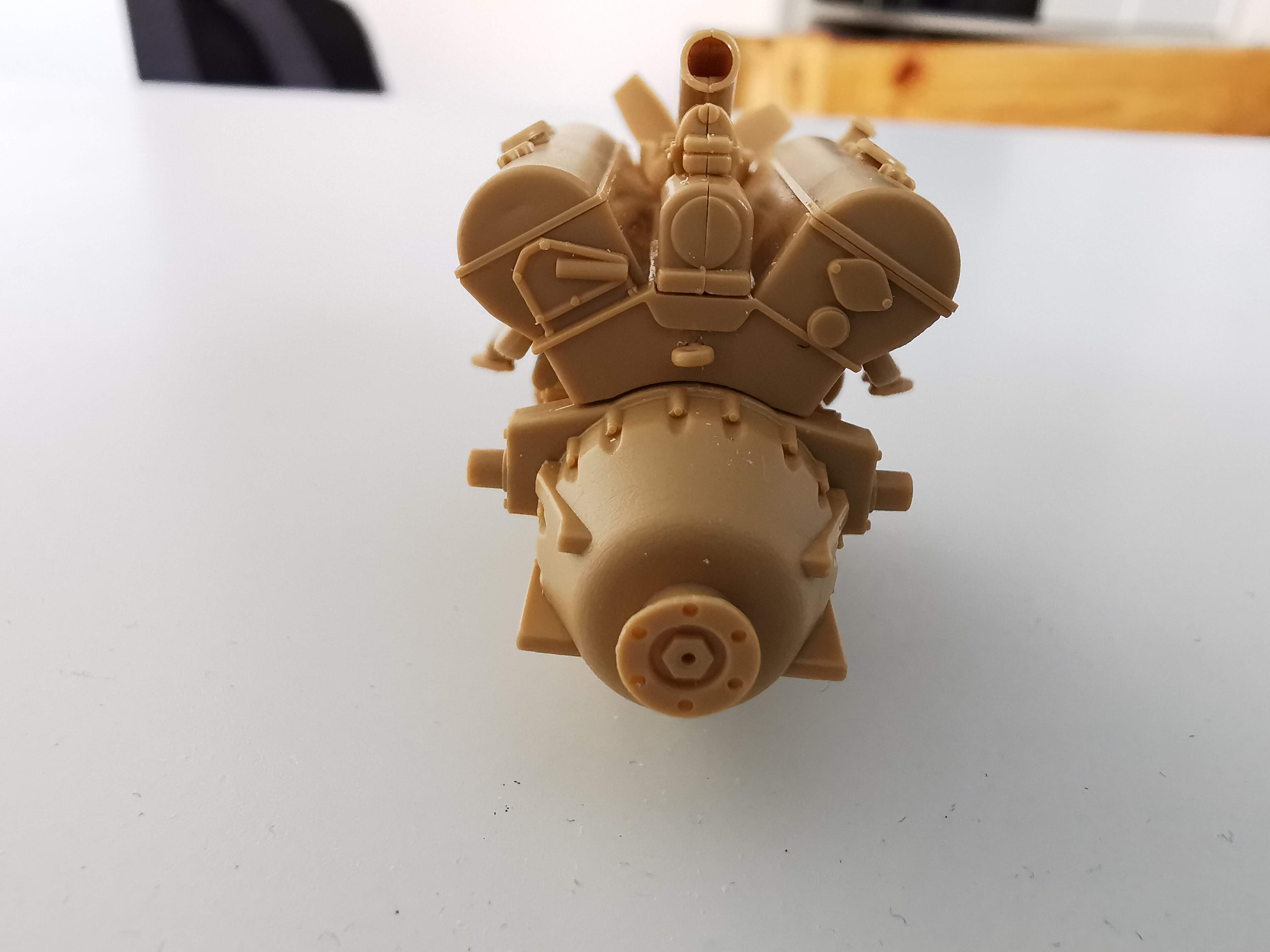
The gap in this image:

seems to be caused by mould seams and/or uneven mating surfaces.
3 Likes
Could you explain in more simple?
Because I’m not fully getting what you are trying to say.
I’m getting that I should test fit every part, but I’m doing that already most of the time.
I don’t fully get the filing part, do I need to glue them and after that file it flat and more even?
Also, how do I get putty in those very very small gaps?
And what do you mean by the ‘mat’ surfaces?
I make a note of the Needle files to get them for a next project.
Where would I be able to get them?
1 Like
I will answer the questions about moulding technology in greater detail later.
Needle files: Ask google for needle files or naaldvijlenset
Mating = paren but in this case it is about the surfaces where parts are glued to each other.
If one part has a flat surface and the other has an uneven surface there will be gaps.
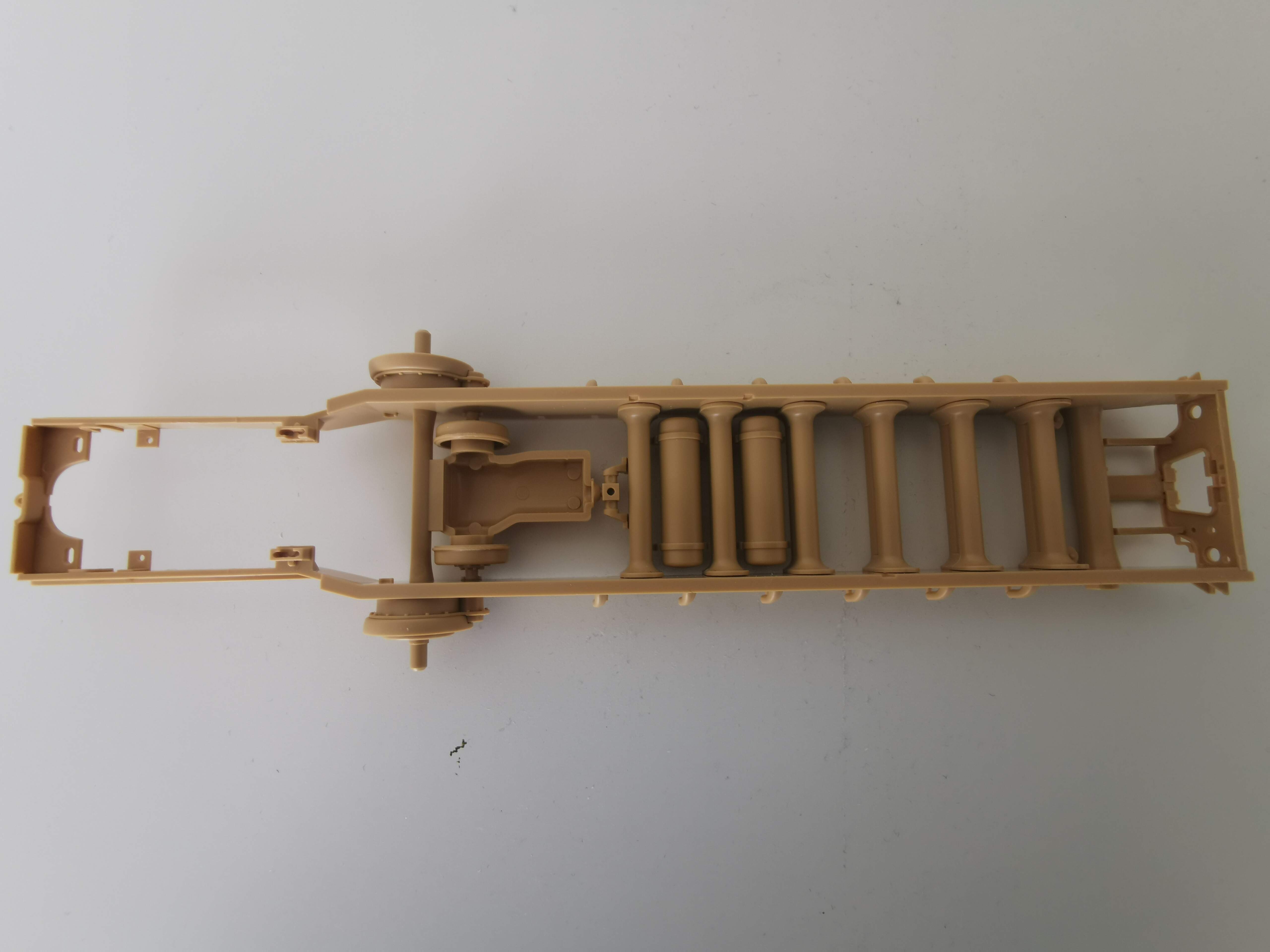
I have made an update on the post as I have moved on a next step of the project.
Please check the post regularly to get all the updates as I’m building along and working on the project.
I think it is better that you post a new message on this thread to add images as you work, rather than edit the original one. It is easier to follow.
And the chasis looks good!
1 Like
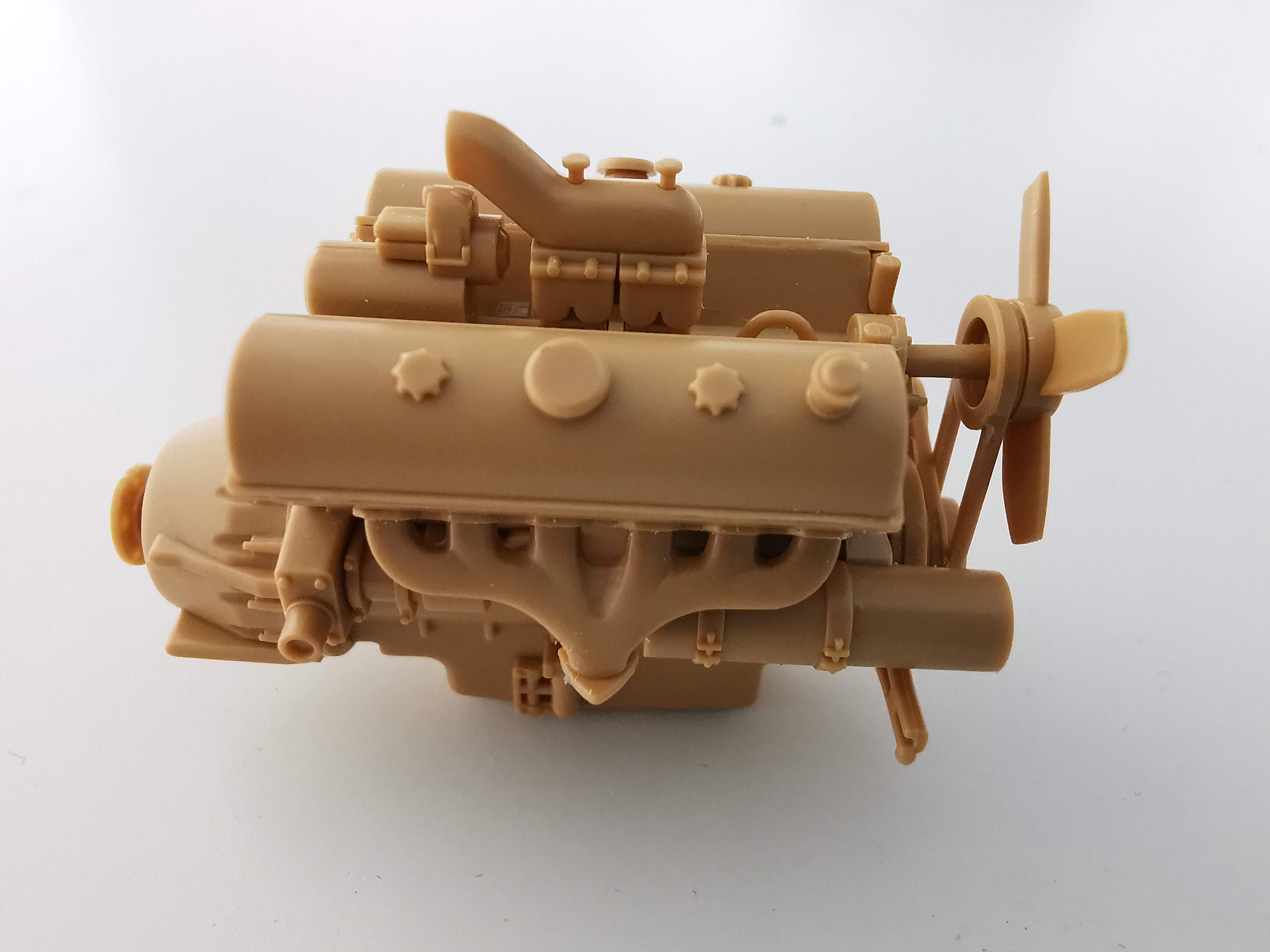
The parts G17 and G10 make up the carburetor, this assembly mounts on top of the main engine block made from parts G23 and G25.
The joint between G17-G10 lands on top of the joint between G23-G25.
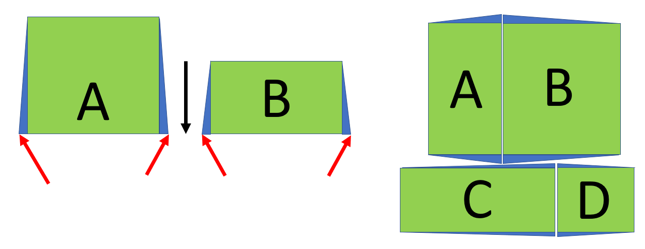
A mould for moulding melted styrene to make parts in a plastic kit must have release angles. This can be seen on box shapes, like the boxes moulded on part D32 (lids are 2 x E14). To get a box out of the mould it can not have have sides that are exactly parallell to the ejection direction. If the real object is a rectangular box the model part will have to be a trapeze.
Parts A, B, C and D should have the shape marked by the green areas. The narrow blue triangles (grossly exaggerated) show the needed release angles . The black arrow shows the direction that the parts will be pushed out of the mold. The red arrows indicate the corners where the mold will usually be slightly rounded, either by design or be getting worn by usage. The parts popped out of the mold will have the shape given by adding the blue triangles to the green rectangles where the corner indicated by the red arrows could be flared out due to the rounding effect.
If the blue triangles wasn’t there the parts would be difficult (causing breakage) or impossible to get out of the mold. It is possible to mould a rectangle but it usually requires a slide mold.
When parts A and B are assembled the result will not be a rectangle, see shape AB on the right.
When AB is glued on top of the assembly CD there will be gaps.
AB and CD could be compared to G17-G10 glued to G23-G25
7 Likes