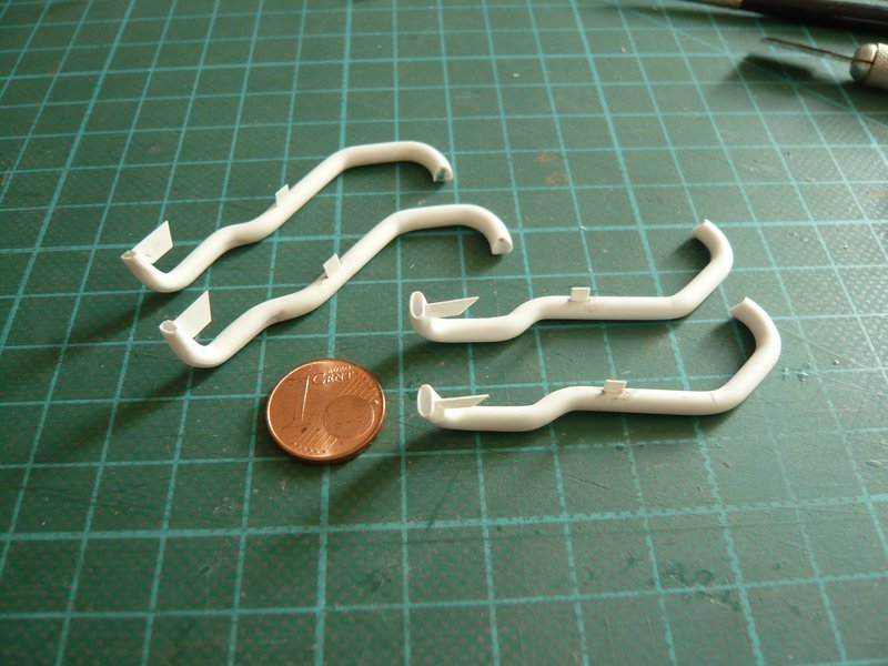
Hello everybody,
now missing only the outlet openings that I wanted to try again. 
The difficulty is, as I said, the central drilling, which you cannot do it immediately with the final diameter, which is why this time I drilled a dummy (Ø 3,2 mm) in smaller gradations. 
After center punching as central as possible I first started with Ø 1,3 mm, specifically about 6 mm deep, that means gradually in and out, so there is no chip congestion. 
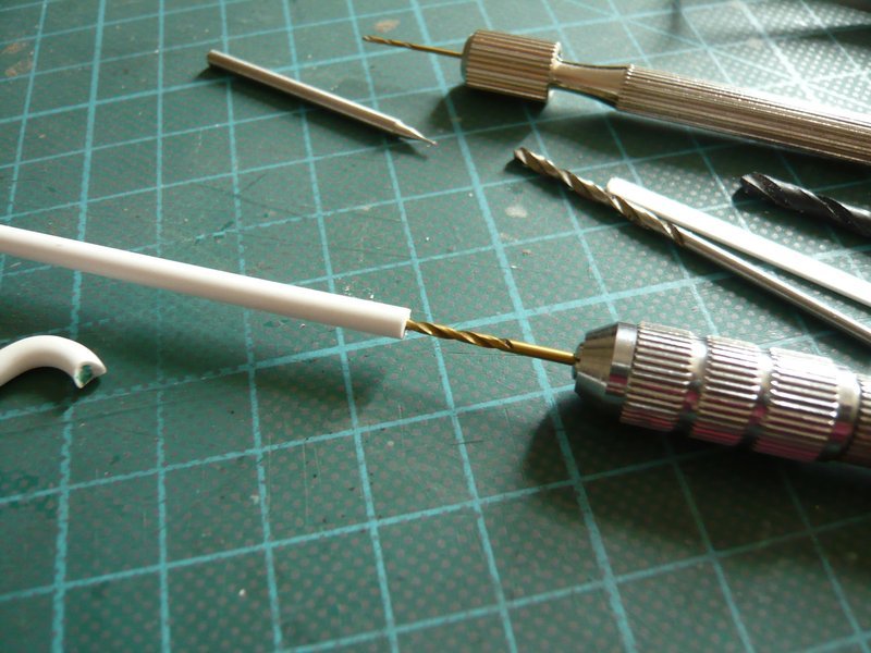
And that looks already pretty centrical. 
Thereafter followed Ø 2,0 mm,
Ø 2,3 mm,
Ø 2,5 mm,
and finally still a slight countersinking with Ø 2,7 mm for reduction the visible wall thickness, just because of the optics.
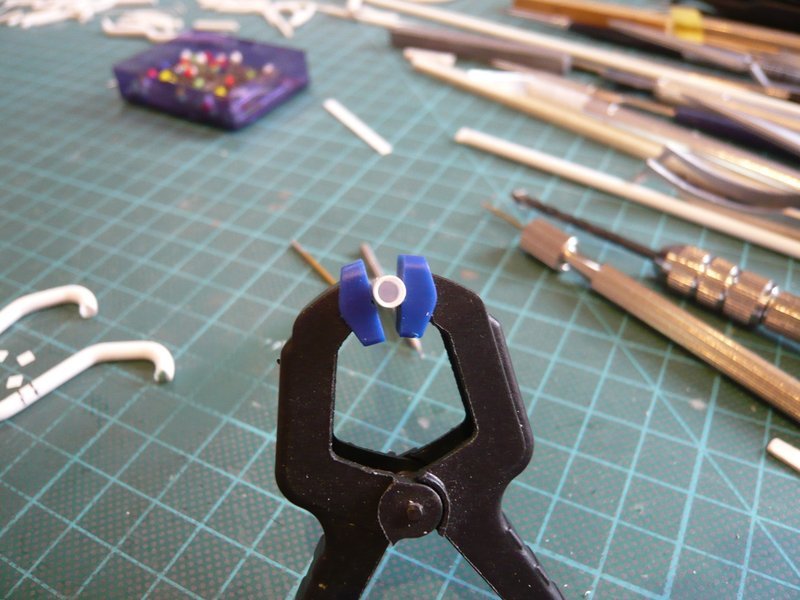
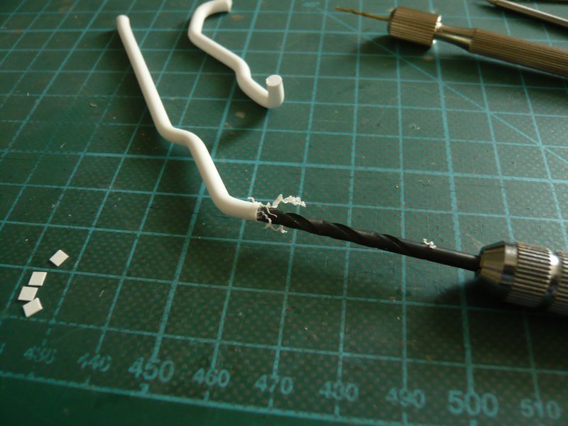
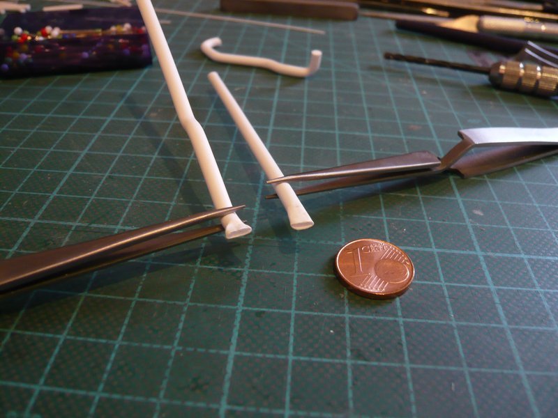
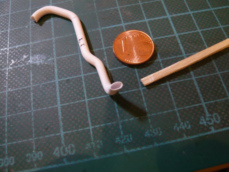
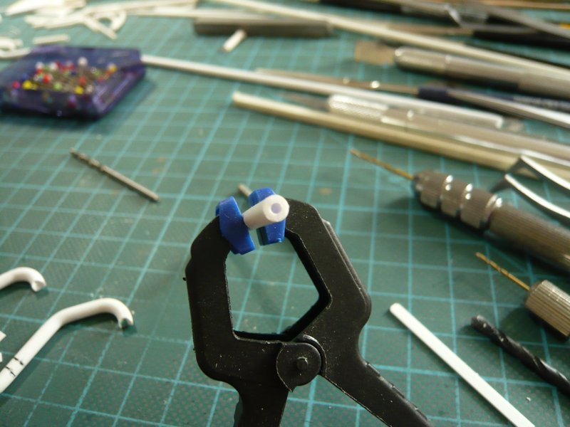
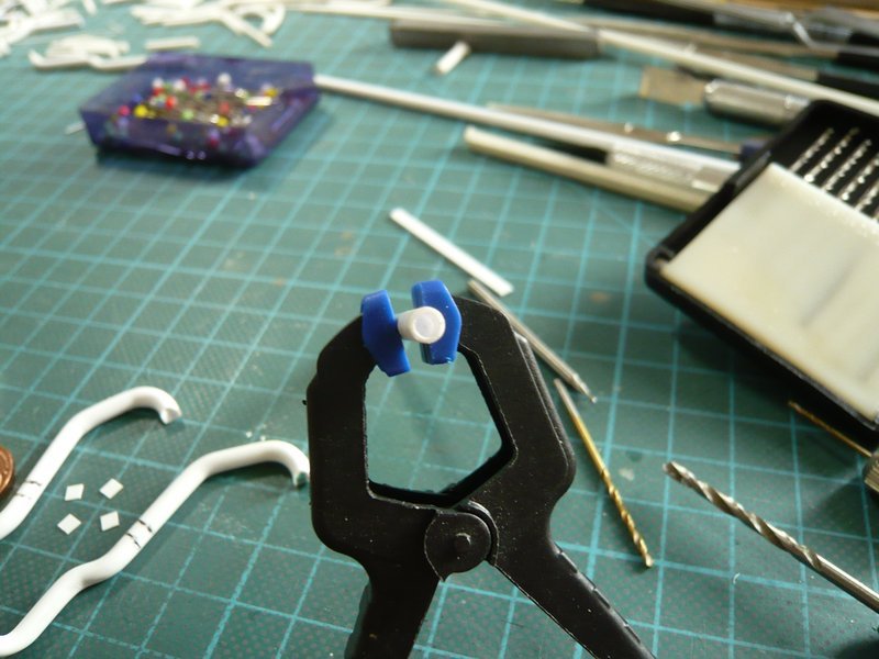
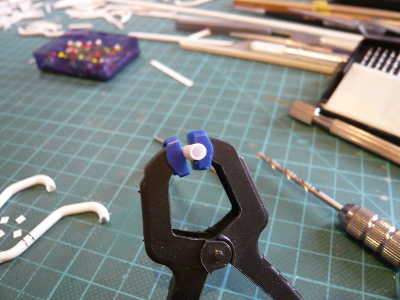
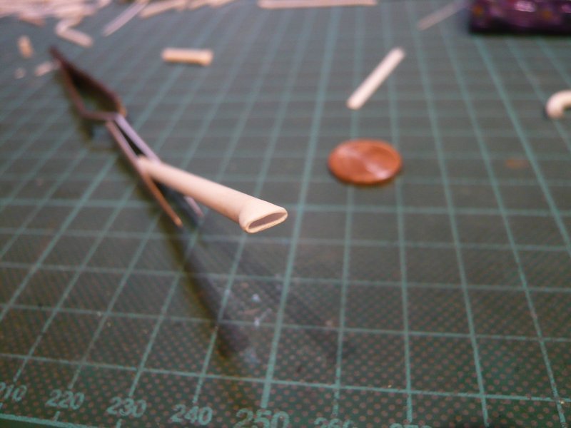
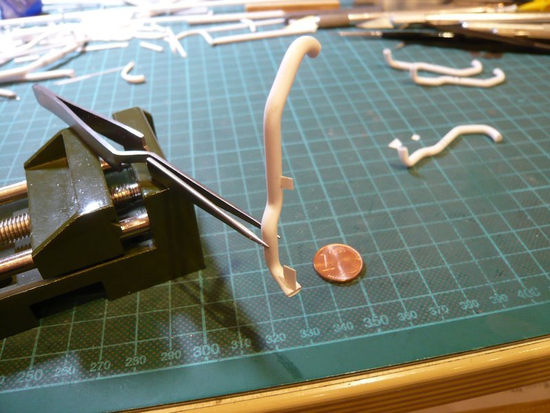
And then I have briefly heated carefully and gradually slowly flattened the front end (about 3 mm) with a core (0,75 mm x 2,5 mm) down to 1,7 mm height, but not this way … 
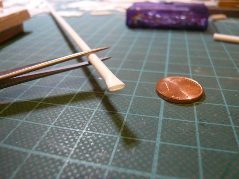
And that can be quite impressive, right? 
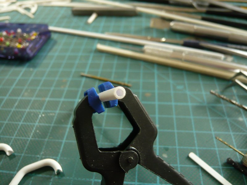
And therefore I can probably now also venture to the final outlets, hopefully it’ll work also as well then.
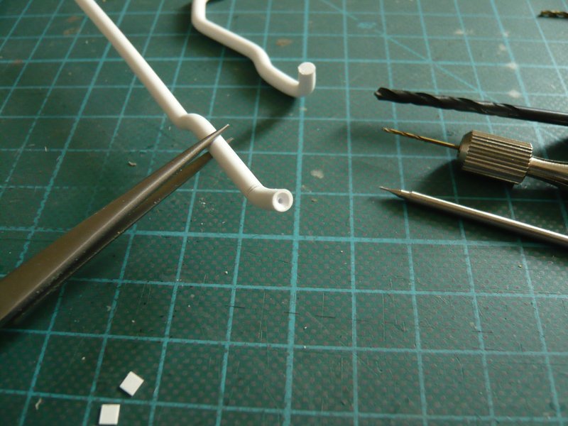
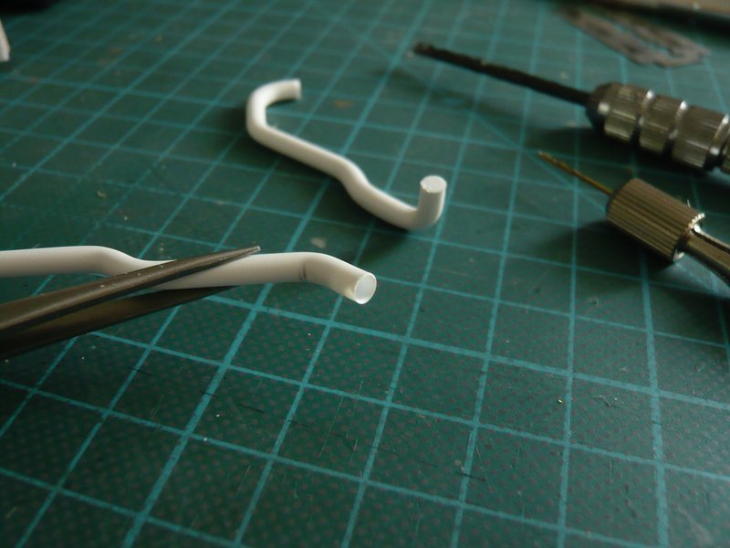
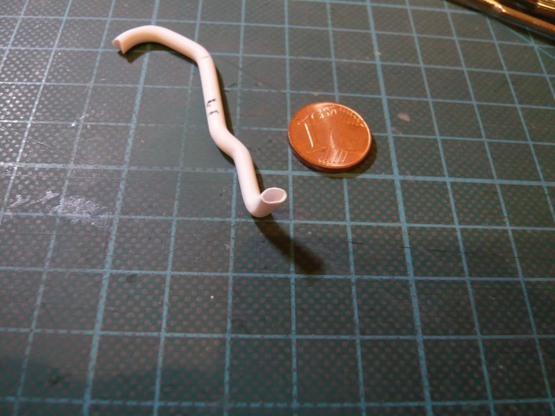
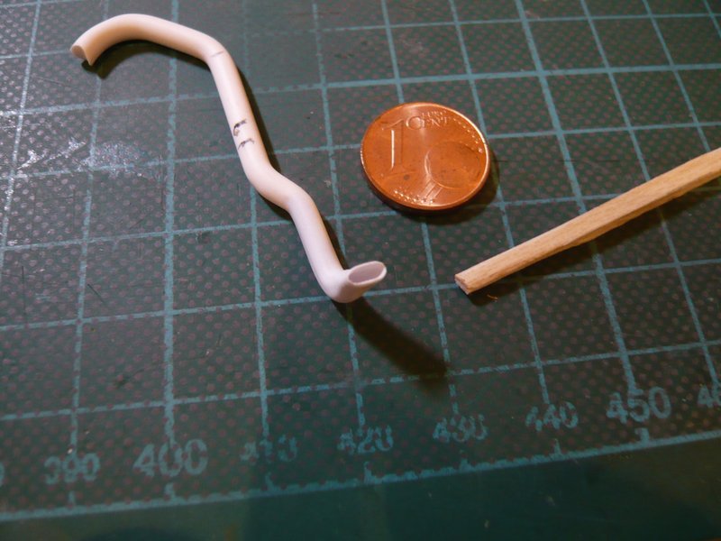
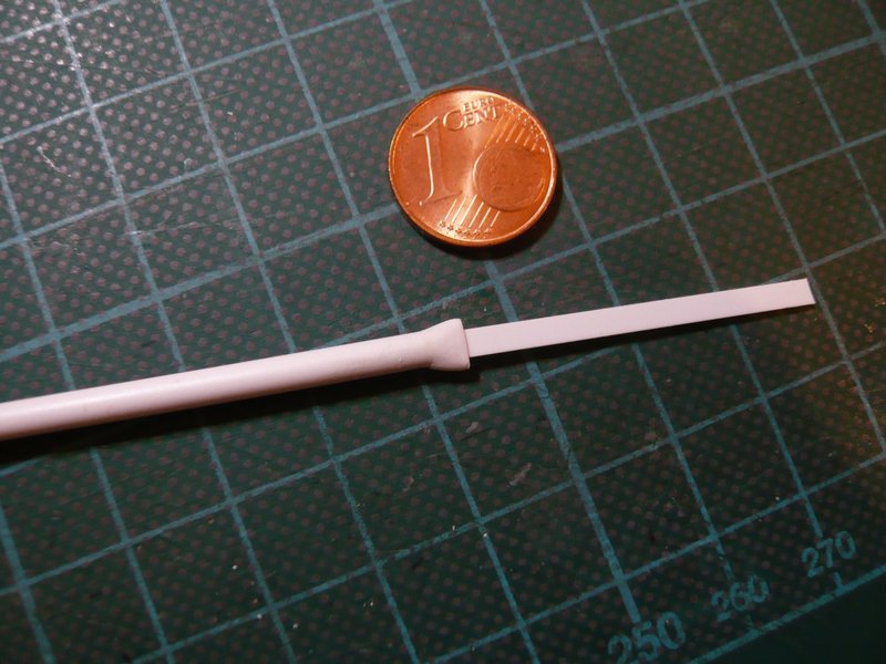
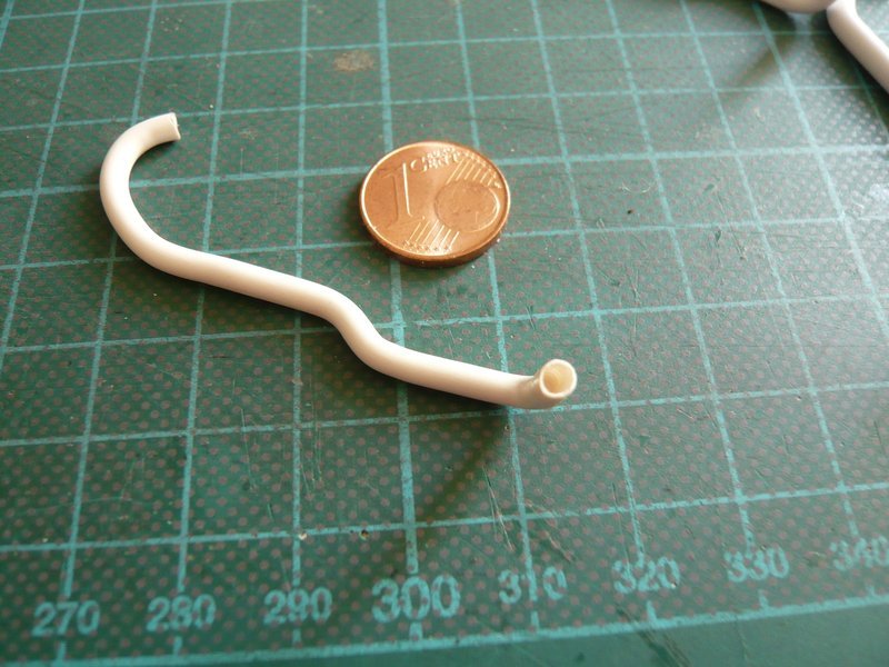
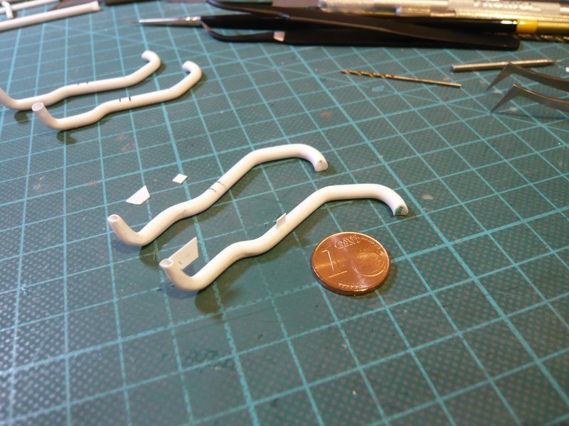
I have made a final test on a real component and thereto used my first 18’’ outlet prototype, which still was lying around and anyway is good for nothing. He still had Ø 3,0 mm and was due to the bendings no longer circular at the end , but came just right as a dummy.
Its end I have drilled out to Ø 2,5 mm,
and then flattened, as usual.
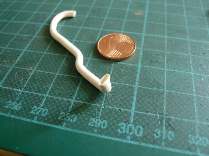
As can be seen, one can scratch the outlet opening also directly at the bent outlet.
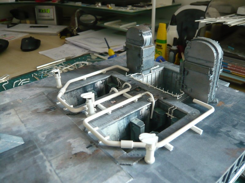
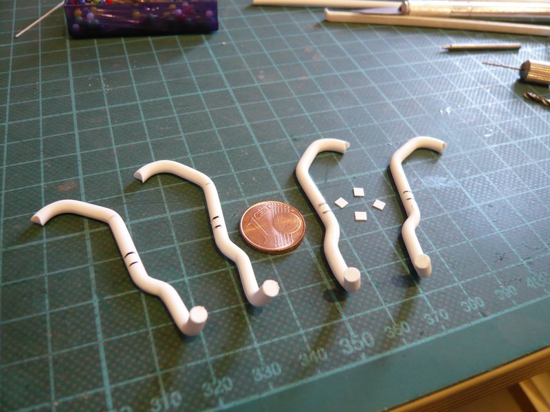
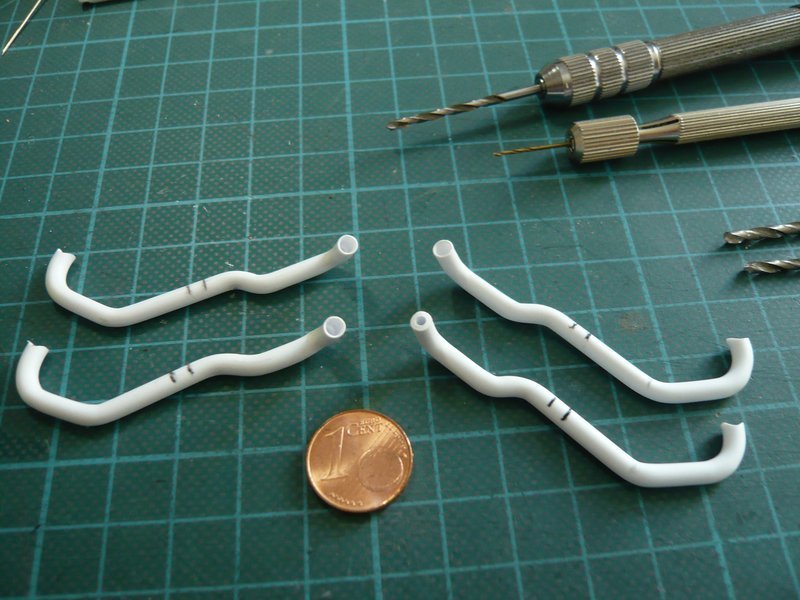
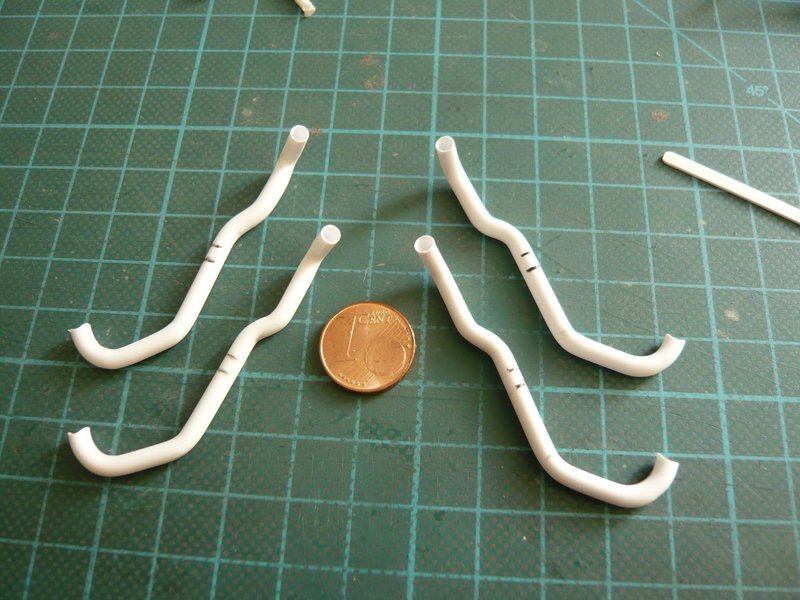
And therefore I can now also get down to business with the four final outlets (Ø 3,2 mm). 
And this I have implemented now, in hopes that it will fit somehow. 
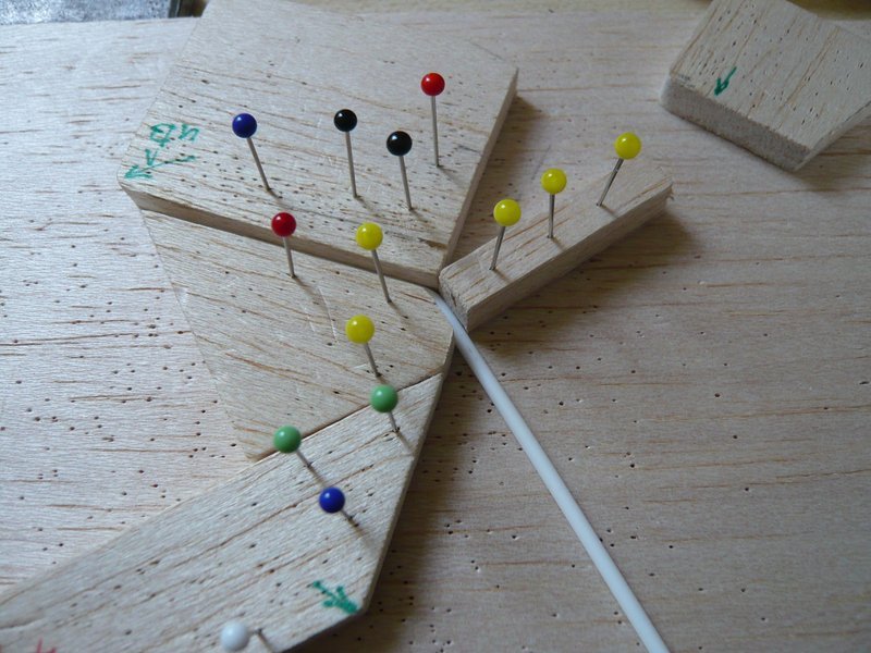
First, I have drilled out the final four 18’’ outlets, as already described.
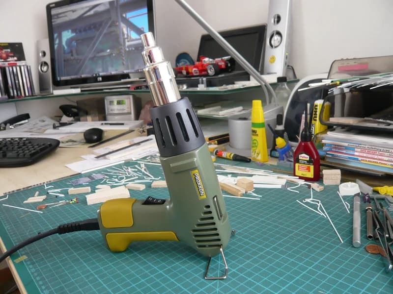
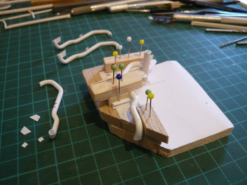
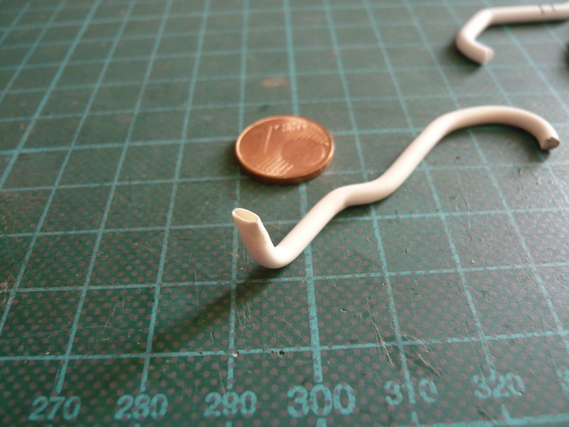
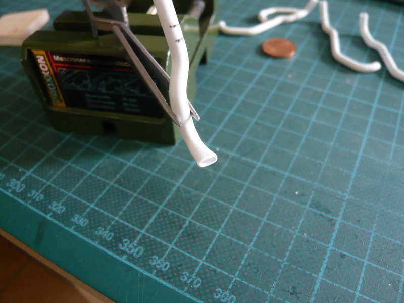
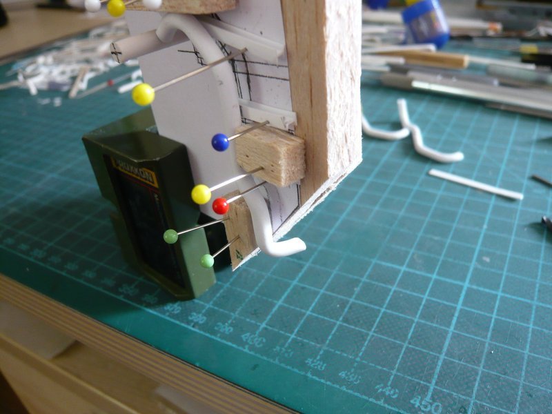
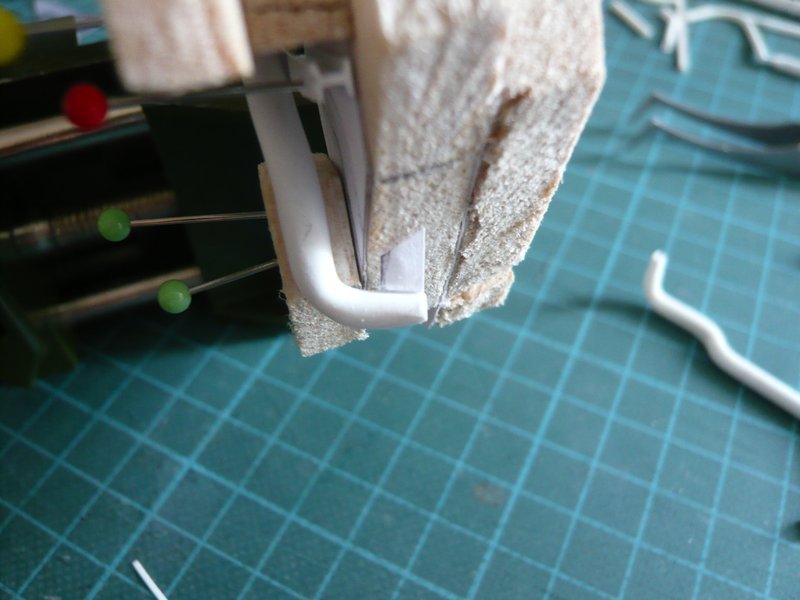
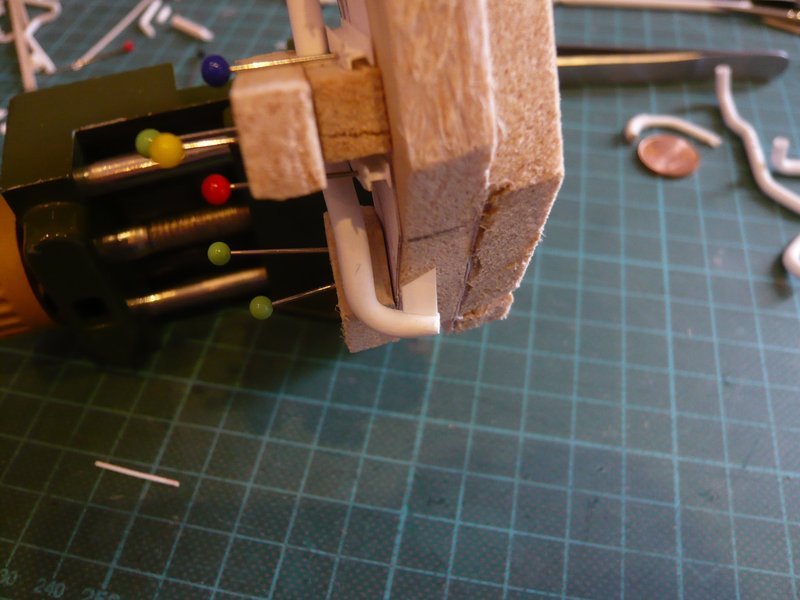
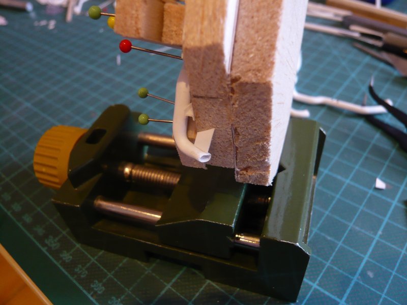
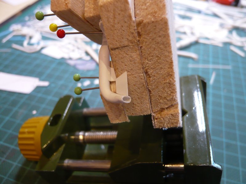
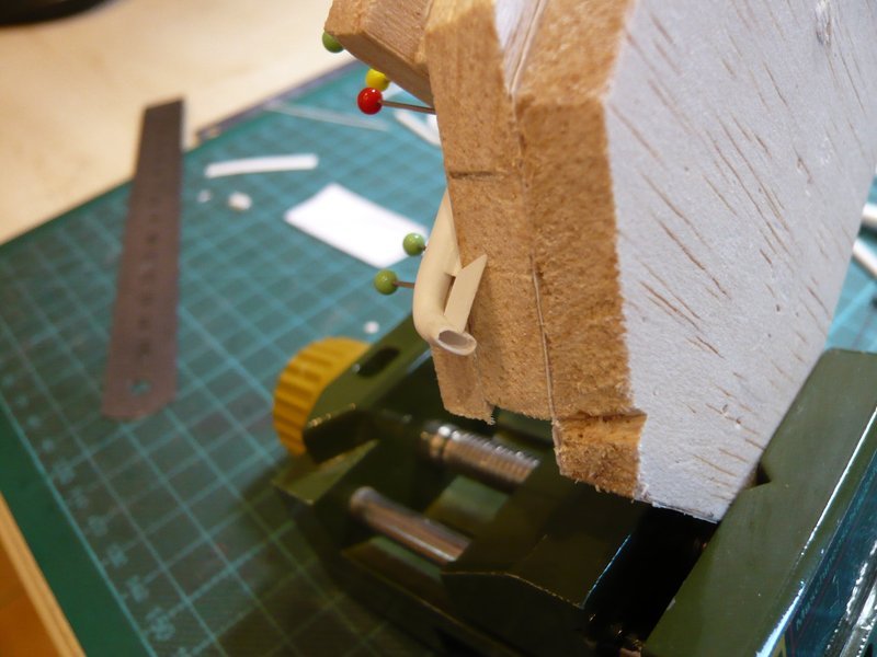
So far so good, and now came the cautious forming of the outlet openings with the help of the Proxxon Gun, for what I have inserted a core.
Nevertheless, one must be extremely careful during heating, so that the thin-walled opening is not shrinking suddenly. 
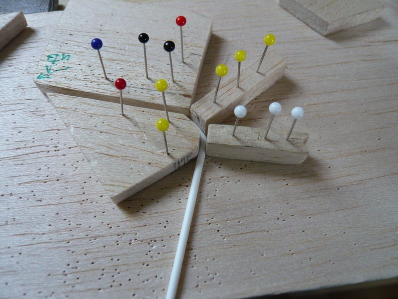
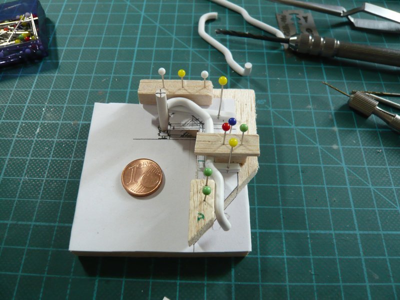
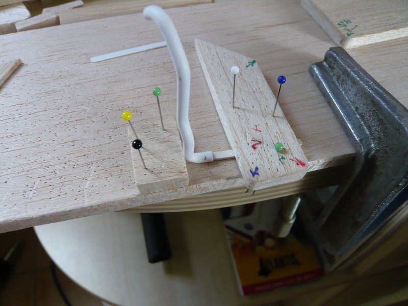
And how the subsequent fitting shows, the position of the opening under the balsa support looks quite passable.
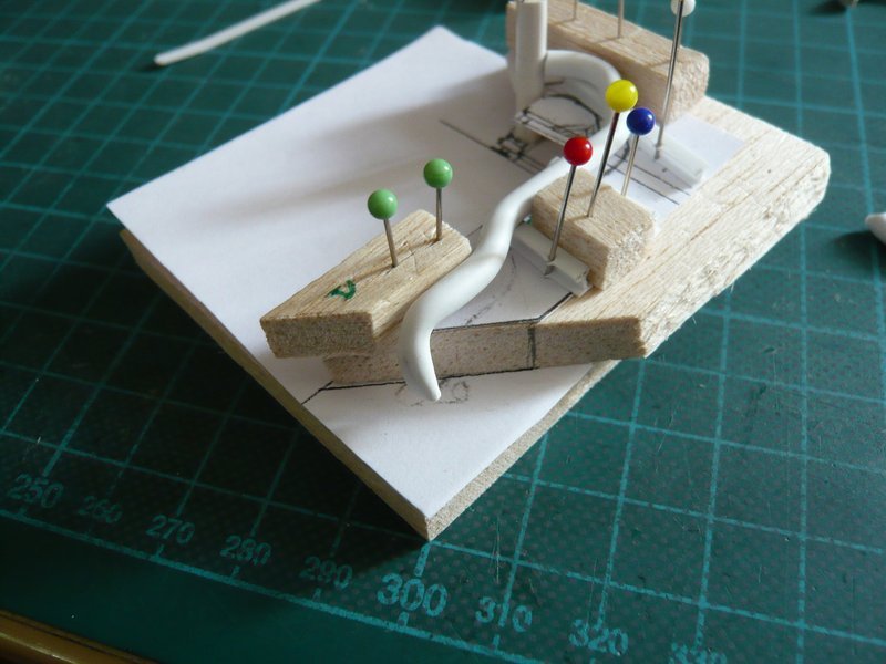
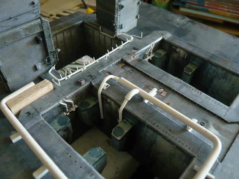
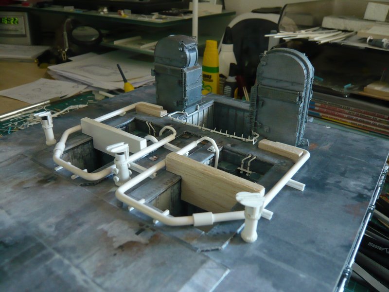
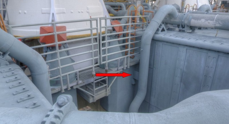
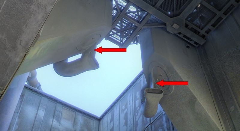
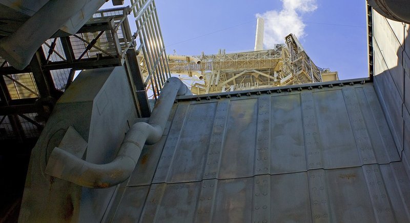
And now to the lower support plates, which can be seen in this panorama of the STS-134 on the MLP 2.
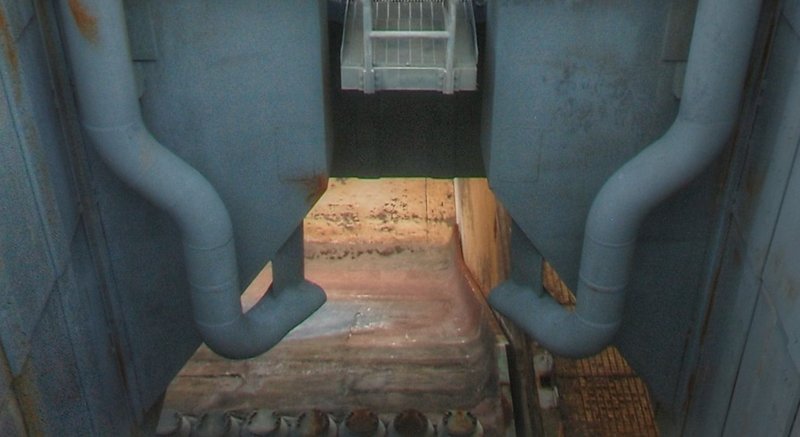
Source: nasatech.net
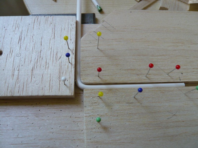
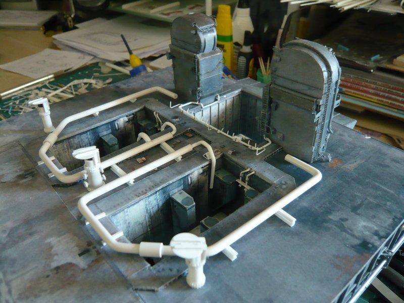
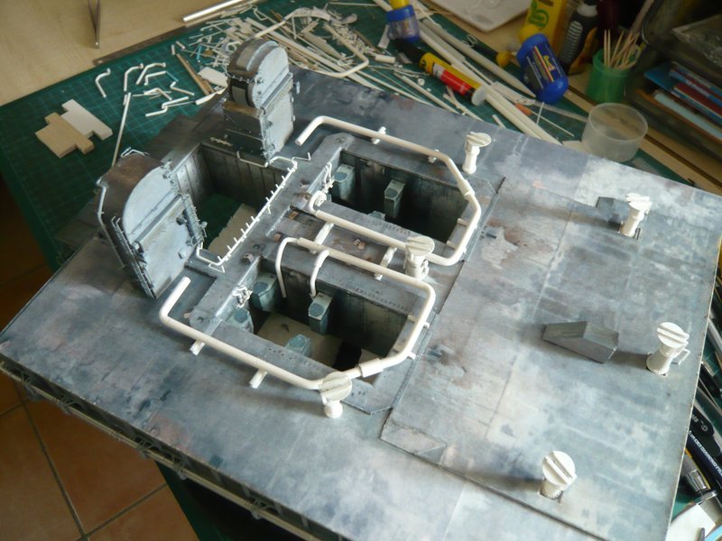
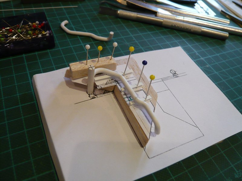
First, I have tested my estimated size with a paper dummy, which was still a bit too small.
With the adjusted support plate of 0,3 mm Stytene it looks much better already. 
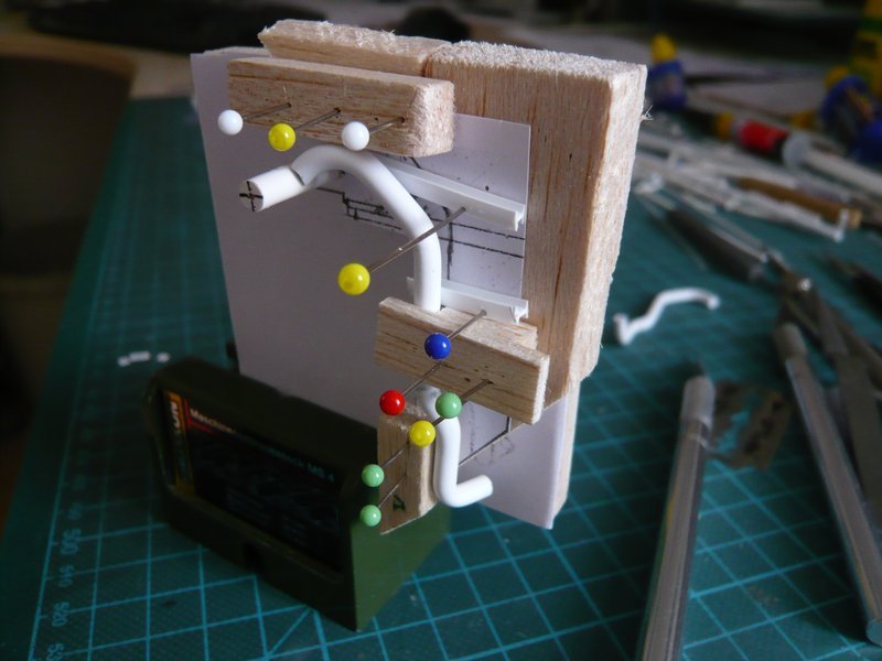
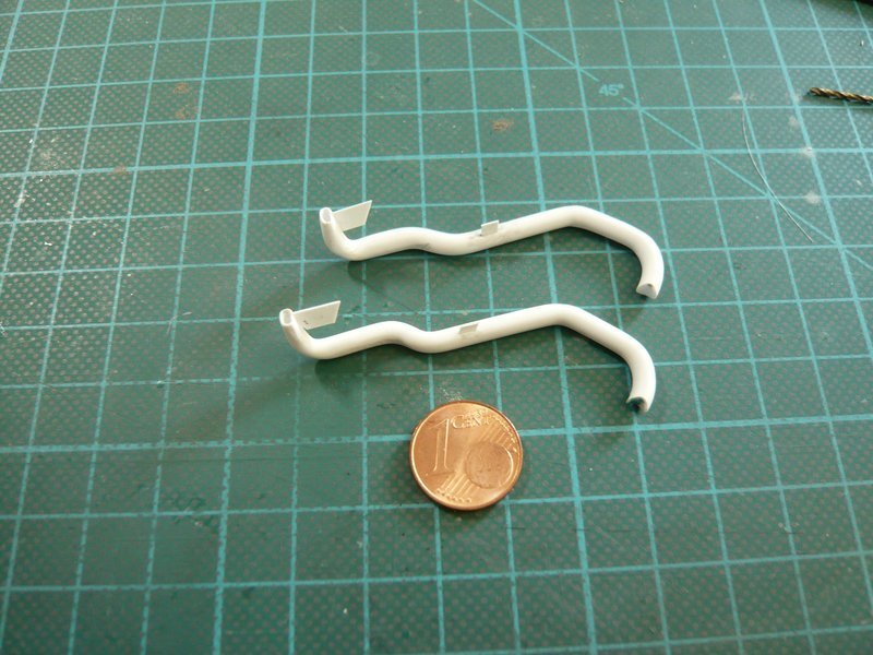
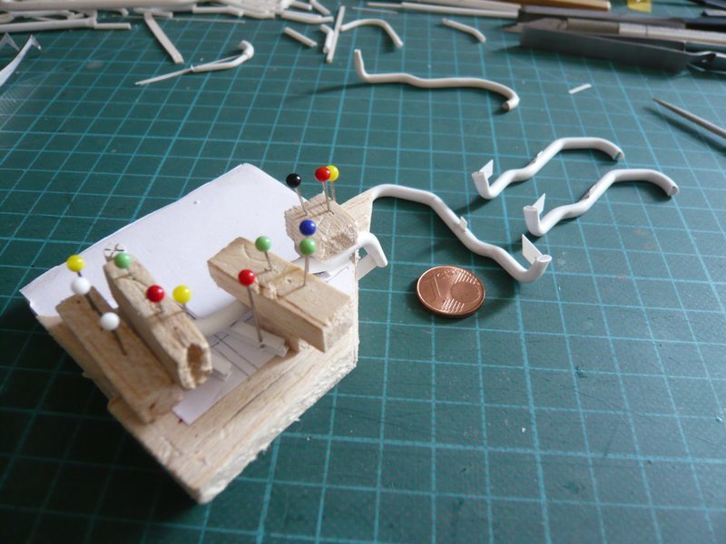
So both plates can be glued now on the outlets in place.
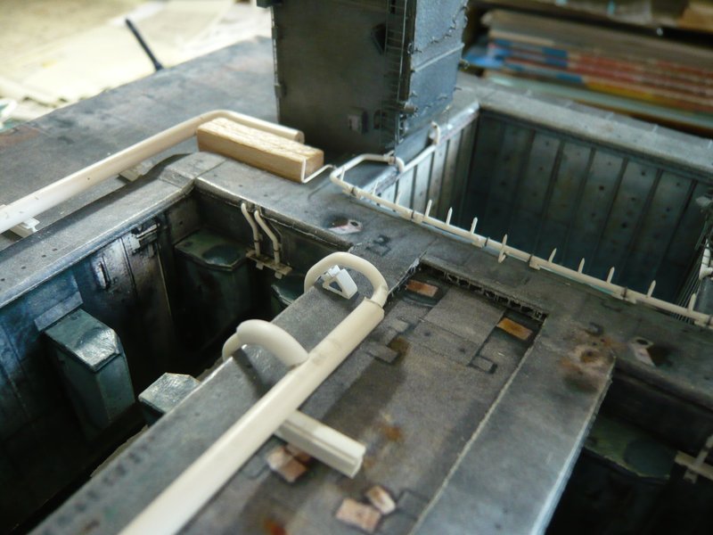
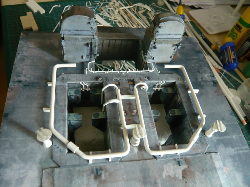
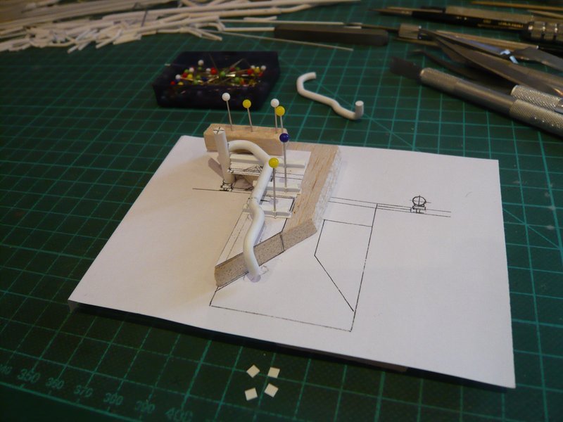
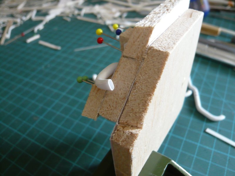
But fast nor a quick update, the lower support plate was once more modified slightly and now stands vertically,
and then it was glued above the outlet opening.
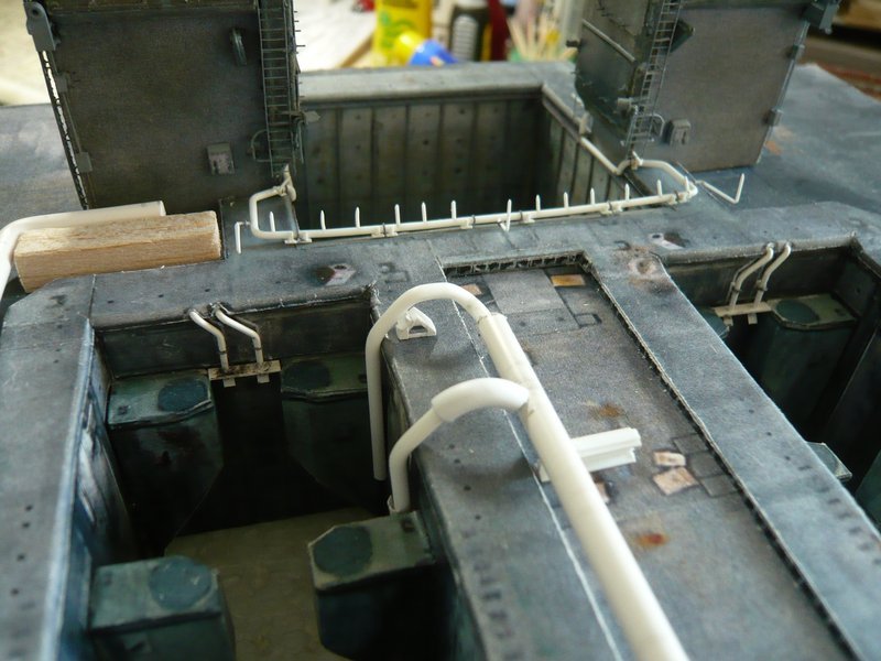
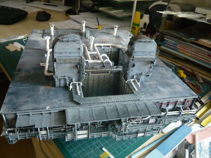
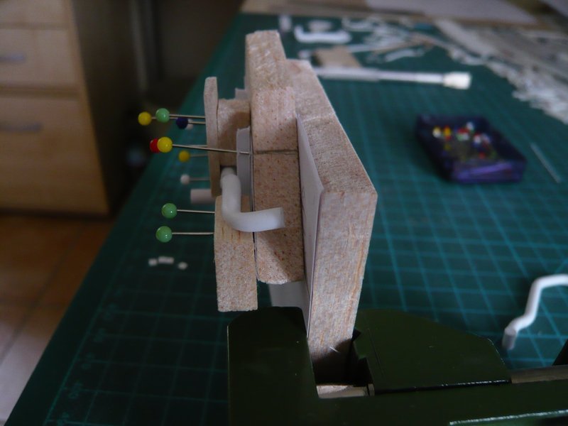
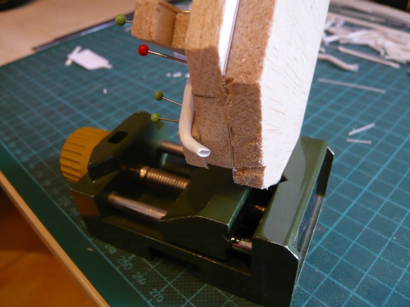
And then came still the upper support.
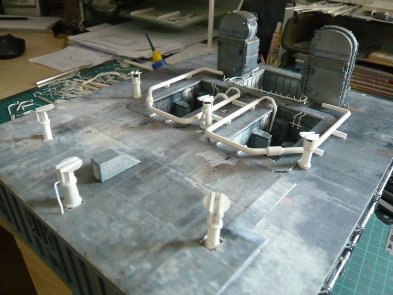
Now first take a deep breath, folks. 
Thanks for watching and stay tuned. The SSWS is a true challenge,  which is still not finished, therefore you must be tougher than the rest like me.