Space Shuttle Launch Complex 39A with Challenger STS-6 (1:144)

Hi folks,

here is still a question to the expert round, what do you think wherefore these screwings are good for, which are located at all outlets (6’’ - 9’’ - 12’’ - 18’') of the SSWS?


Source: nasatech.net

Of which there are a total of 18 pieces there, if I’ve counted correctly, although here some are covered.


Source: nasatech.net

Are these possibly vent openings or inspection ports?

What’s going on folks, no ideas or no fancy, or both?

I think, that vents shall probably not come into consideration, because the SSWS pipes are only during the launch under pressure. The rest of the time the entire system is open, from the two 36’’ feed pipes in the SRB exhaust holes,


Source: nasatech.net

to all outlet openings of the two ring lines.


Source: nasatech.net

I rather think that these openings are probably some sort of inspection ports for access for Mini Cameras periodically to check the pipes for cracks and wear. Because at these pipe-bends the stress as well as the wear of the pipes are greatest, this makes most sense to me.

Be that as it may, I’ve tried to scratch these nipples.

As already indicated, the nipples are relatively small in my scale (1:160), only about 0,4 mm/0,2 mm in diameter and about 0,4 mm high.


Source: nasatech.net

If one would be pretty exactly, one might poke a brass rod Ø 0,2 mm into a brass tube Ø 0,4 mm with 0,09 mm wall thickness, as one can see here.

But the tiny “screw” on the right side is hardly to be seen still.

This couple one could now stuck into a 0,4 mm through-hole, but this effort is not worthwhile.

Therefore, I would be satisfied with a Styrene variant, whereto I have drilled out my dummy outlet,

and glued a short stub Styrene Ø 0,4 mm.

And this stub I’ve then reduced to approx. 0,4 mm in height.

And since this result seems perfectly adequate, I will probably stick with it.

2 Likes

Makes sense as they appear on the top and near corners.

1 Like

Hello everybody,

because today is Sunday, there is a longer session, which is why at the end I want to give still a look ahead how it goes on shortly.

Finally the last two 18’’ outlets without rejuvenation also have received their support plates.

Then I have shortly pre-drilled the upper bows with Ø 0,5 mm, inserted rods (Ø 0,45 mm) for the nipples and glued them with MEK,

which then were cut and carefully sanded down to 0,4 mm height.

And then there were also still the six 18’’ outlets with rejuvenation which I had almost forgotten.

Therefore the same procedure all over again on these bows.

Now missing only the nipples of the two front 12’’ outlets, which previously still have to get their outlet openings with baffles.

There are still these two 9’’ outlets (Ø 1.4 mm), which branch off before the 12’’ outlet from the 24’’ ring line, then run through below the SRB Blast Shields,


Source: nasatech.net

and feed the line with the outlet nozzles on the rear wall of the SSME Exhaust chamber,


Source: nasatech.net

which I have completed for some time, as well as the tricky Firex line.

And at the other end of the 24’’ ring lines it goes on behind the TSM’s with the 16’’ rejuvenations (Ø 2,5 mm) which are tapering one more time to 11’’ (Ø 1,8 mm) after the first bending,


Source: nasatech.net

and end in the SSME chamber in these pipes stocked with eight outlet nozzles.


Source: nasatech.net

In order to continue with these details, I had to make measurements and scalings again.

And as it looks like, it will be probably again pretty tricky, I guess.

1 Like

Hello everybody,

here still a small addendum to two outlets that are missing yet, these are namely those four 6’’ outlets (Ø 1 mm) here, which although were to be seen already, but have not yet been regarded.


Source: nasatech.net

These transitions branch off from the ring lines, run under the SRB Blast Shields, and reappear between the front SRB Supports, whose ends with the outlet openings also already exist.

And the two 24’’ ring lines are fed in through these two 36’’ inlet pipes in the corners of the SRB chambers that were already shown also.

Here is the upper confluence into the ring line,


Source: nasatech.net

and here the lower end with the coupling elements,


Source: Troy McClellan

which must not be missing.

And in order that during the further adaptation and assembly of various outlets everything goes well and the ring lines cannot shift constantly themselves, I have precautionally carved even more mounting aids.

These mounting aids are then certainly also indispensable during subsequent assembly of so many pipe supports.

1 Like

It Nevers goes below an amazing level for this attention to detail :+1:

Yep, John, since that time I had arrived at this level, there was no way for going back.

In this sense I fully agree with Tom Cruise: Mission impossible!

1 Like

Hello everyone,

initially I still want to show the two 12’’ outlets, which now have got their outlet openings and baffles as well as the nipples.

And after that it initially went on with the 9’’ transitions (Ø 1,4 mm) of the 24’’ ring lines (Ø 4 mm), standing on a tall support pillar.


Source: nasatech.net

What on the pictures firstly looks really practical and invites for scratching, then pretty shrinks on the 1:1 Sketch again.

After determining of the dimensions of the components began the search for suitable profiles. For the pillar Evergreen rods are suitable with Ø 1 mm (bottom) and 1,4 mm for the upper sleeve, on which a flat 2 mm U-profile sits and on this a small “Sickle”. Of the width for the U-profile a corresponding Evergreen channel would be suitable, but is unfortunately too thick for this filigree support and the sides with 1 mm too high.

That’s why I preferred to bite the bullet and have scratched the profile of 0,15 mm Styrene. For the sides I have sanded down an Evergreen strip 0,25 mm x 0,5 mm to 0,15 mm and then glued with MEK.

And the difference is clearly visible, as one can see here.

Then bending was indicated again, this time with the 1,4 mm rod,

what agrees very well with the sketch.

After that I’ve drilled a hole with 1,4 mm in the front inner corner of the SRB Blast Shields, and made a test that was okay instantly.

And that also fits well with the underlying 12’’ outlet.

Now is still missing the support pillar, which I’ll make next.

1 Like

Hello again,

but initially the 9’’ outlet still received a few small details.

At the feedpoint of the 24’’ ring line is a small thickening to see, for what I have punched a small Styrene disc (0,5 mm) with Ø 1,6mm, which has already been glued, as can be seen in the following figure.

Due to the small diameter of the outlet of 1,4 mm also the diameter of the nipple is correspondingly smaller with only 0,3 mm, for what only a tiny hole were to drill,

into which my thinnest rod with Ø 0,3 mm was glued. Next to it is a lead wire (Ø 0,3 mm), which I will use for the clamping ring on the other end.

The lead wire I have glued with CA.

And so the final outlet looks, from which I still need a second copy.

And now to the slender support pillar, which stands under this outlet and consists of six parts,


Source: nasatech.net

which I have already prepared and are all quite tiny,

which must be glued together now.

And I can tell you, the mounting should become a tricky matter due to the minimal contact surfaces.

Since I glued these things with normal Revell glue for possible corrections, one can not continue, but must wait until hardening.

And the height of the support I should also check from time to time, since it should not exceed 9 mm in order to fit even under the outlet.

And for that reason alone every now and then a break is necessary, like now, why the base plate and the top plate have to wait.

1 Like

Hello everybody,

and here is the next update.

Since I still wanted to check the total height of the support pillar, I have not initially sanded the tiny rounding in the upper pipe holder, especially since it is anyway only 1 mm x 1 mm “big”.

The problem with this prototype is, that the height of the components should be exact as possible on the tenth of a millimeter, if in the end should be reached the calculated required total height of 9 mm, so that the support fits under the transition.

Subsequently, the support was positioned on the base plate and glued,

and then vertically aligned on all sides vertically.

And so the filigree structure looks, which is very fragile and wherefore the further handling is to enjoy with caution.

With the optical look of the support I am already very satisfied, although actually still missing these two screwings,


Source: nasatech.net

which I wanted to try at least times. In my estimation, one could scratch it by thin rods, which would however be again in the boundary region of the nipples with Ø 0,3 mm.

That would be even doable, although this strip (0,37 mm x 1,5 mm) is slightly wider than the only 1 mm wide plate under the pipe holder,

and through the shadows it could be seen even better in the painted state, questionable would be, however, from what distance …

But more important is the question whether and how the support would fit at all.

And to my surprise, it fits already together relatively well,

although the left side of the pipe hangs a bit in the air, as can be seen more clearly in this close-up.

But this should be still compensable if I sand even a tinier rounding in the tiny pipe holder (1 mm x 1 mm) and it plays along.

Although this support was quite tricky, this looks but overall very well.

Making of the tiny rounding was not a problem, especially since only a hint of 0,15 mm was necessary.

And here is the result,

and because the transition now sits a little bit lower, so far everything is okay.

Therefore, the rounding of the second pipe holder will be made before assembly.

1 Like

Now only the second 9’’ transition is missing, which first had to be bent again.

Although the processes are now already familiar, the difficulty lies in getting the transitions as identical as possible.

These are the individual parts for it, apart from the two rods for the support.

After the filigree U-shaped substructure was scratched, it was time for the difficult assembly of the parts, which was again quite stressful.

And with that the couple was complete,

and could be tried on on the MLP.

Although the provisional attachment of the outlets with Pattex is also a tiresome game of patience and does not last long,

the impressive overall impression is worth the effort, which is why I brought back the Rainbirds again, their scratch building I’ll come back later on.

That’s it for today.

3 Likes

So detailed… Superb work as always :+1:

Thanks John for looking in on me again.

Stay tuned, now the pipes become still smaller and get tiny nozzles.

Hello everybody,

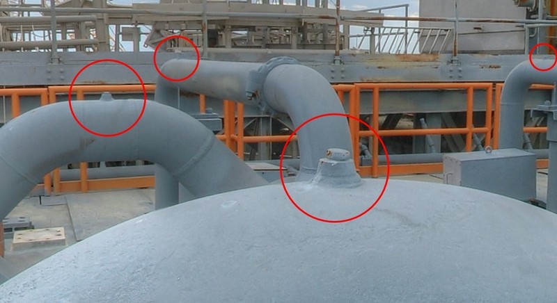
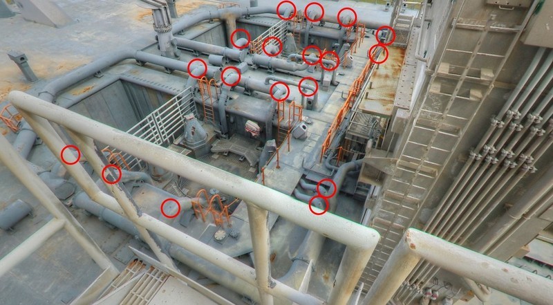
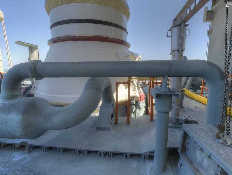
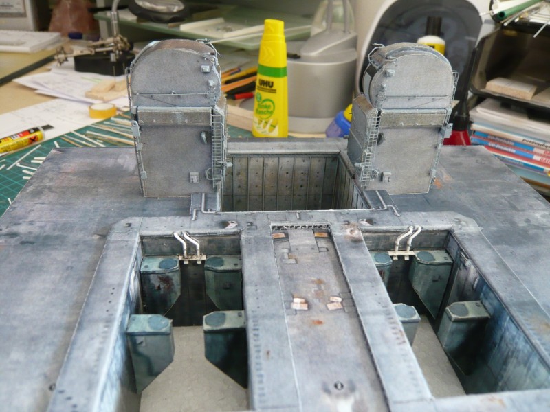
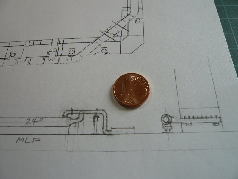
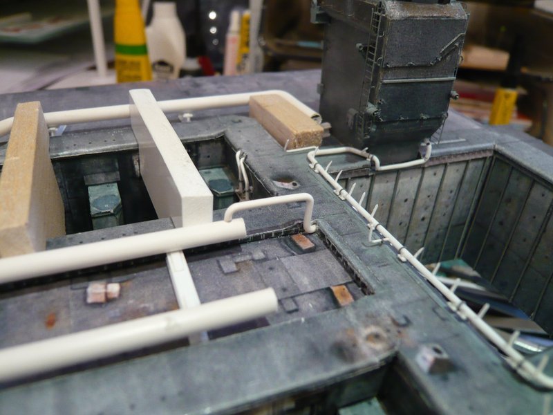
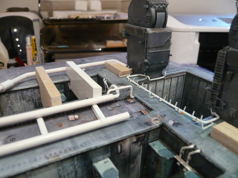
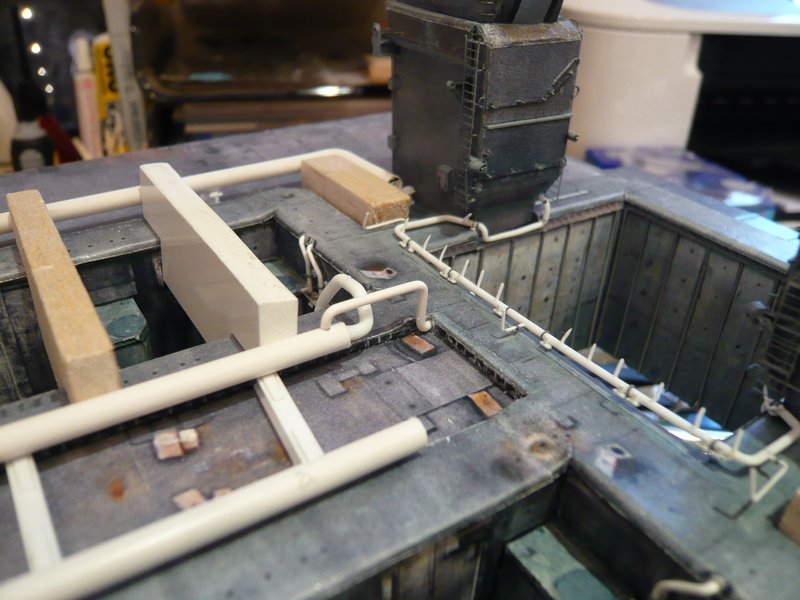
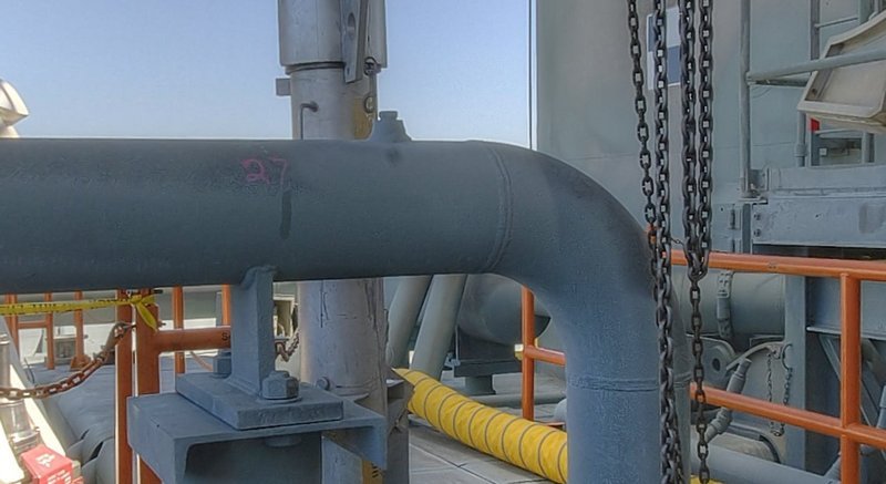
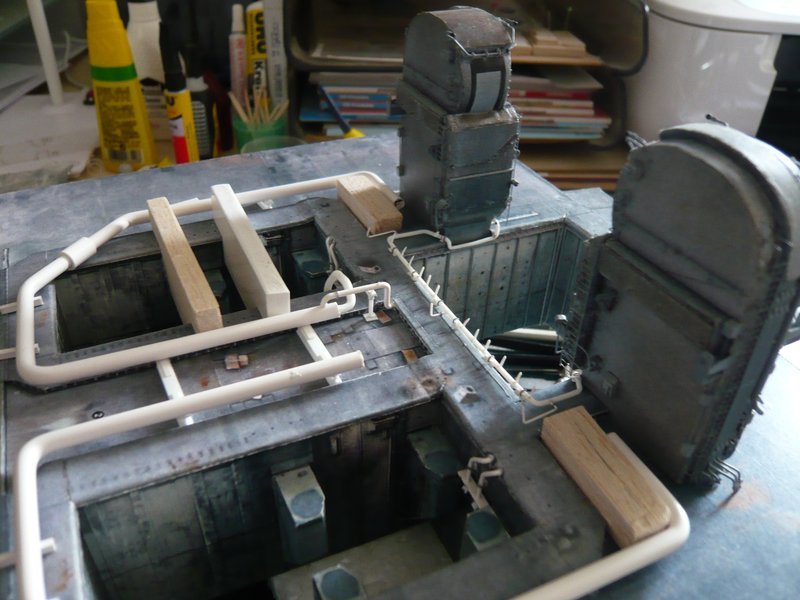
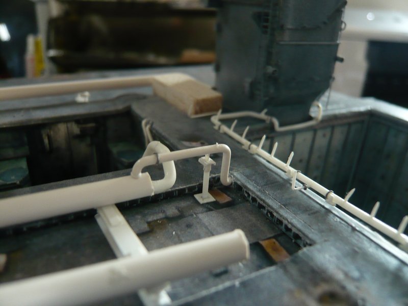
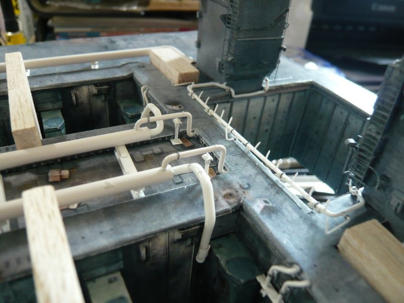
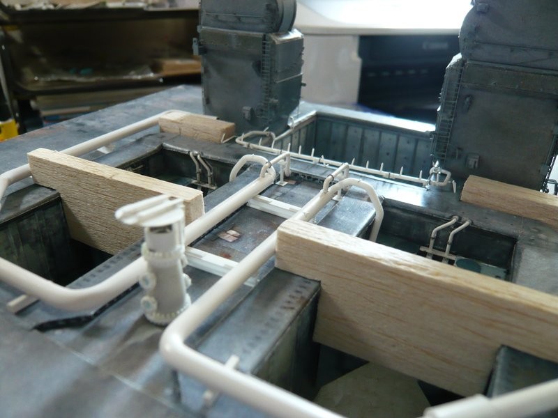
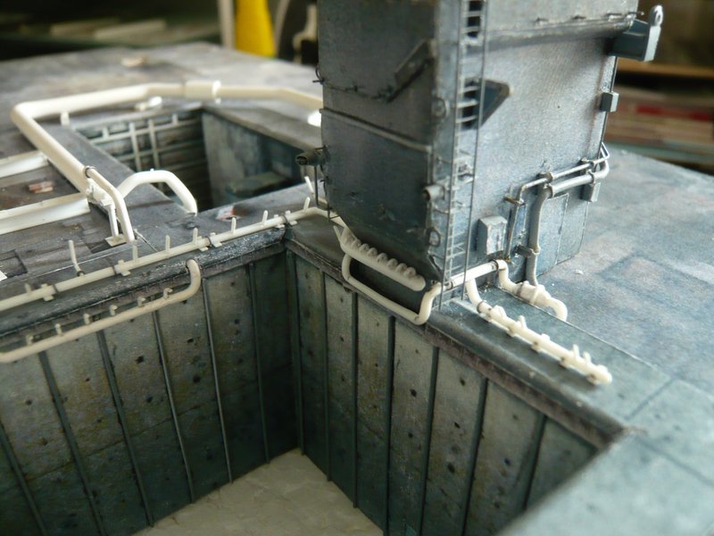
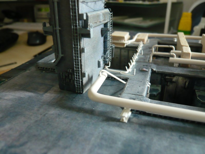
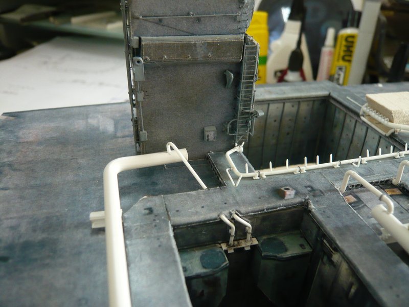
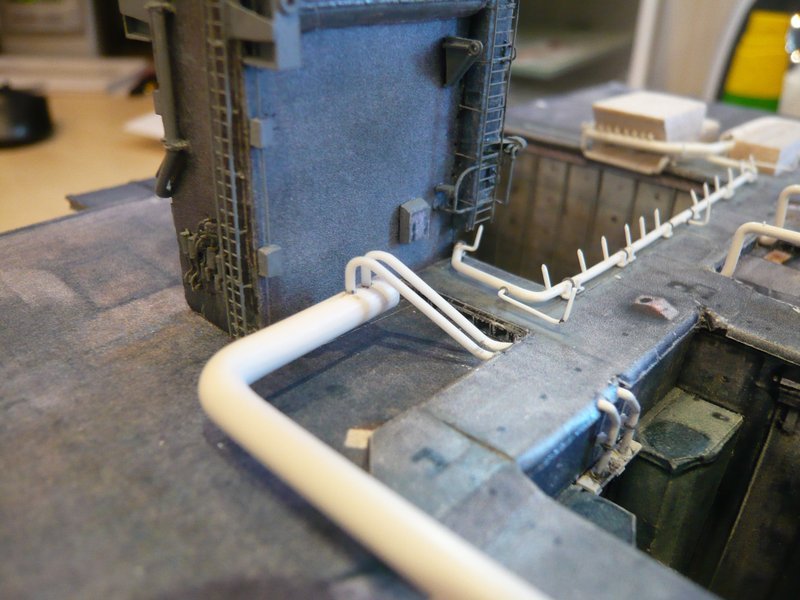
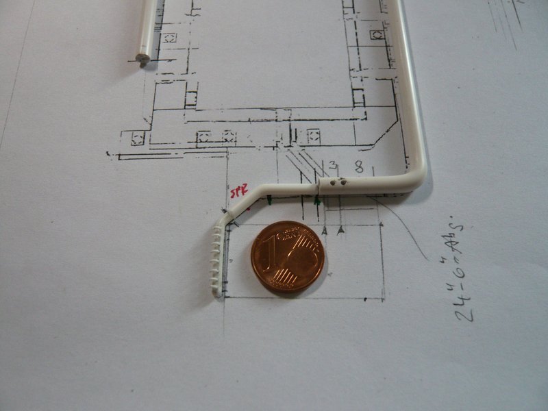
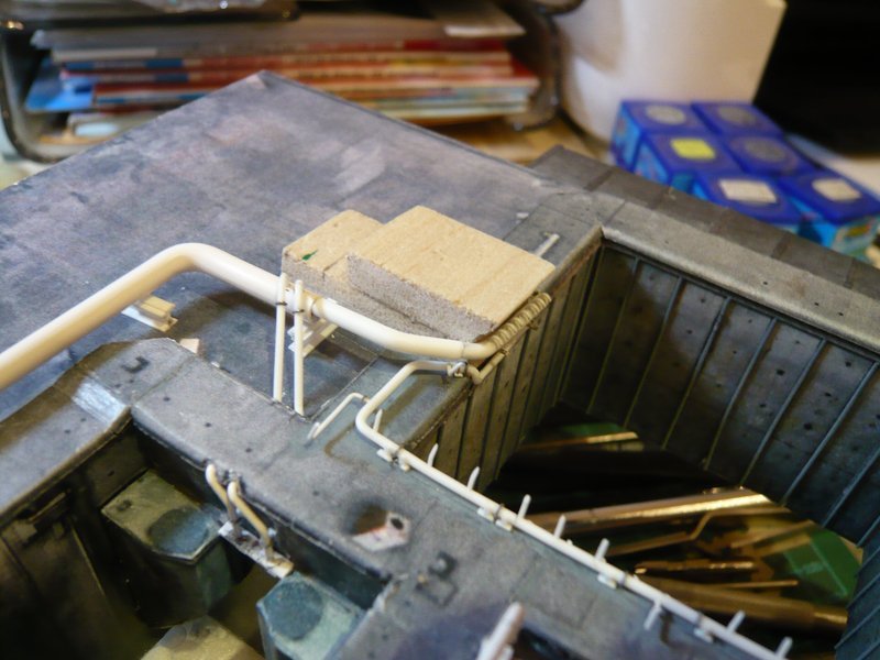
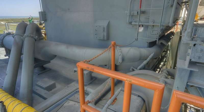
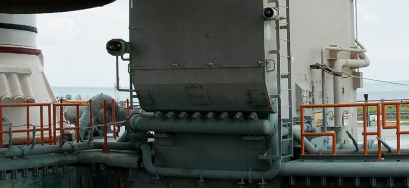
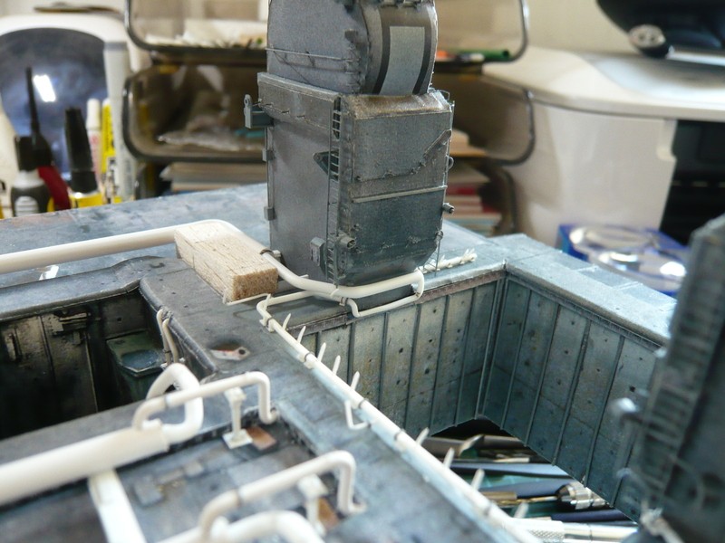
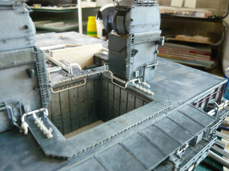
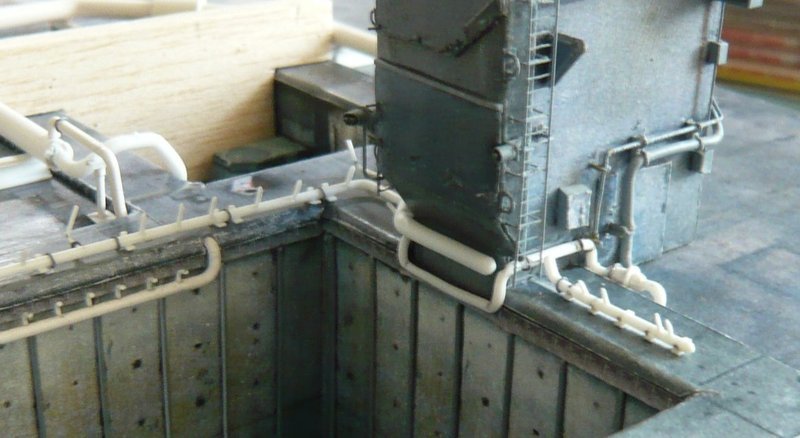
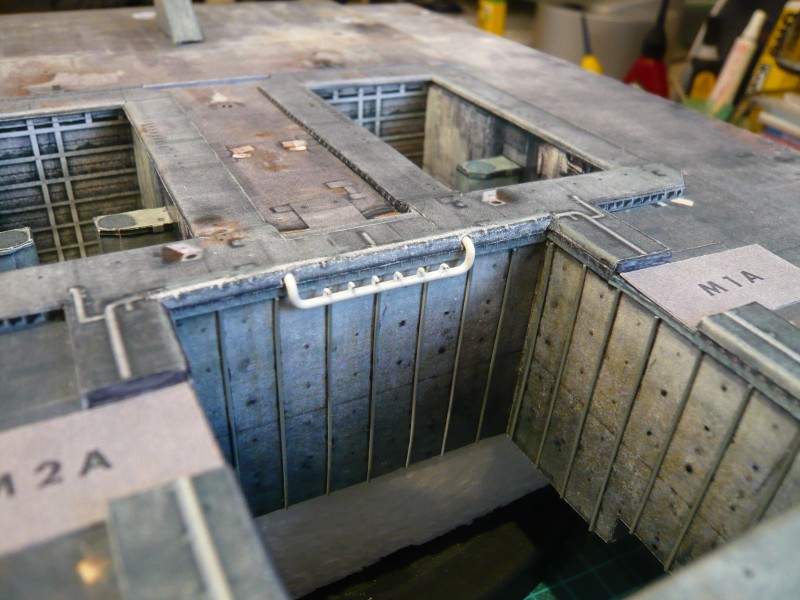
after the outlets in the SRB chambers except for the two 36’’ feed pipes and the nine missing pipe supports are done, it is now time for the last two outlets behind and under the Tail Service Mast (TSM).

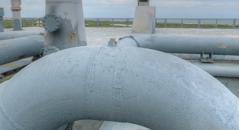
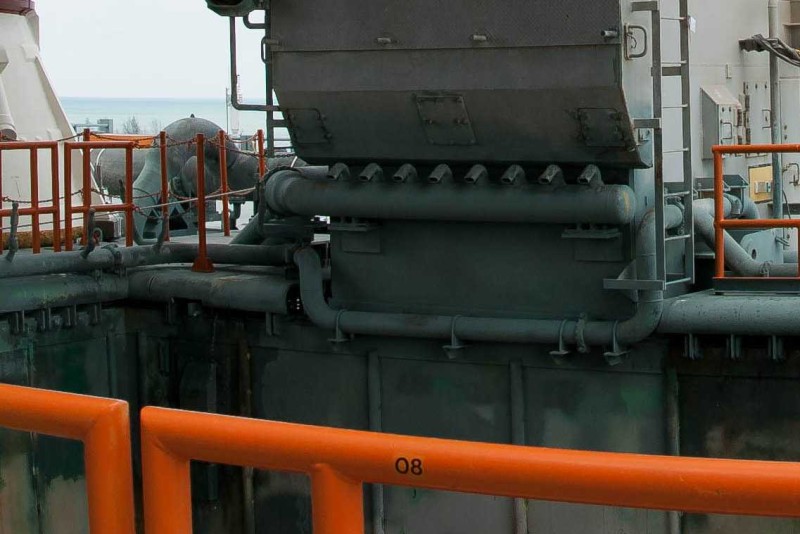
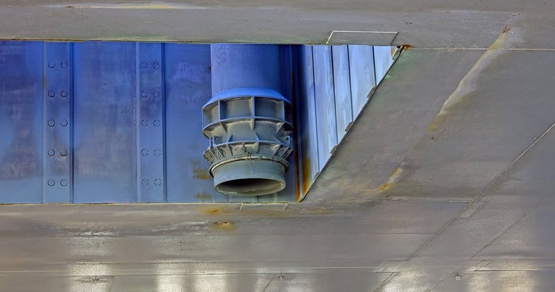
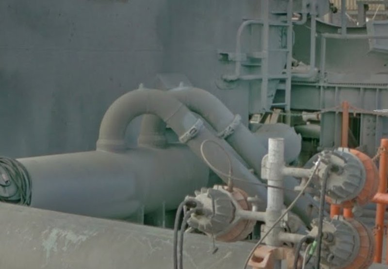
This initially affects the section behind the rejuvenation of the 24’’ ring line to 16’’ (Ø 2,5 mm) just before the corner of the TSM beside the SSME Blast chamber to 12’’ (Ø 2,0 mm), such as re-measurements have shown.


Source: nasatech.net

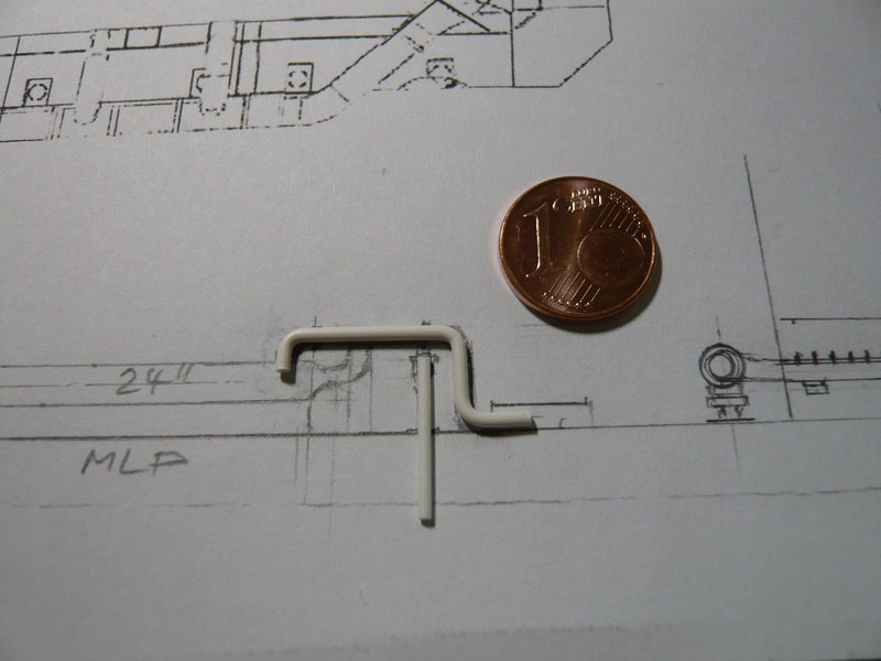
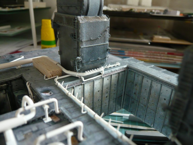
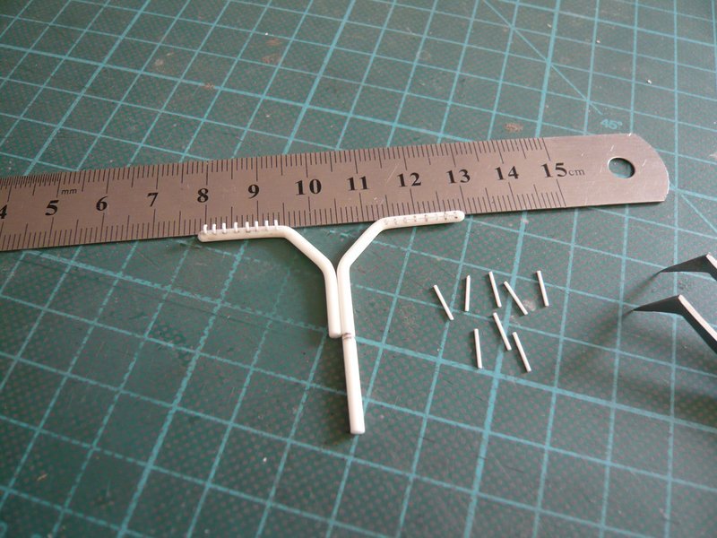
On this pipe sitting eight small bent nozzles, which should have a diameter of about 0,5 mm.


Source: nasatech.net

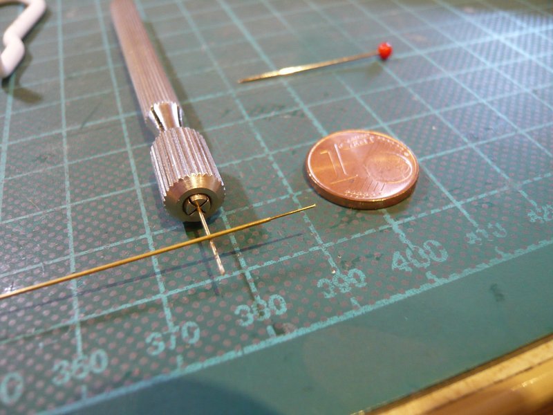
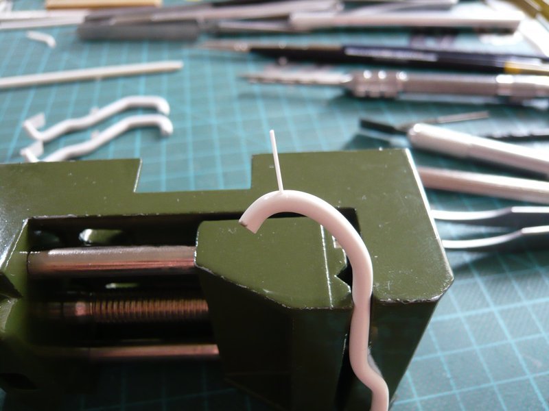
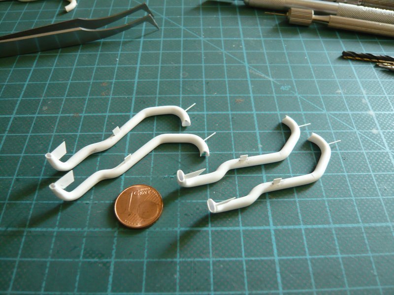
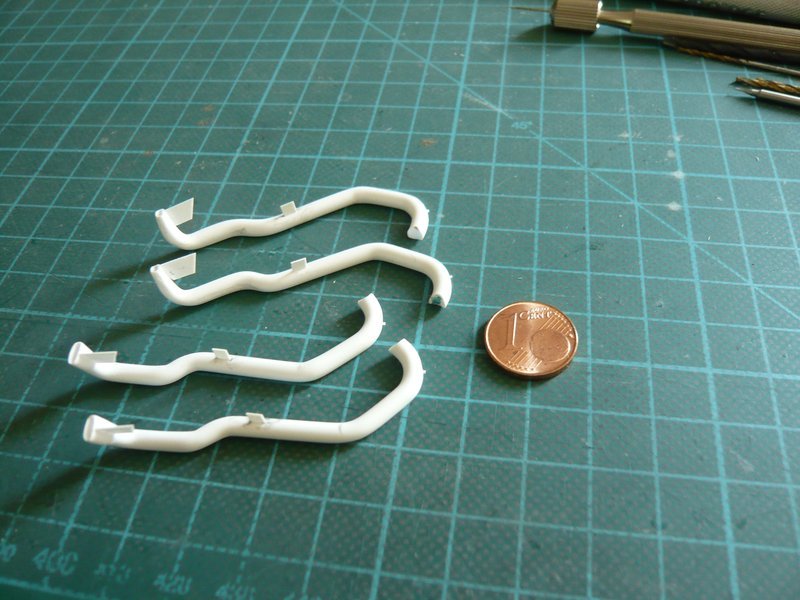
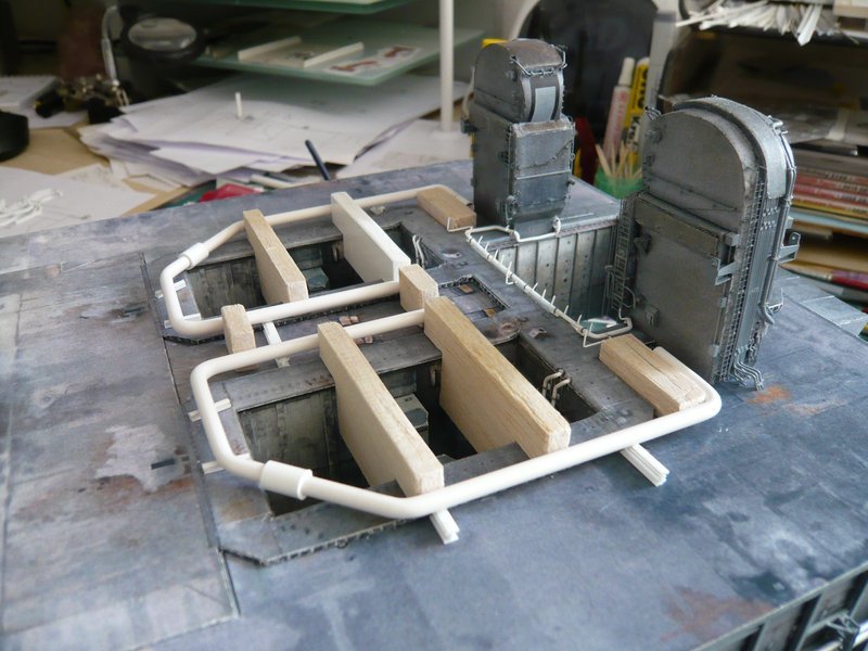
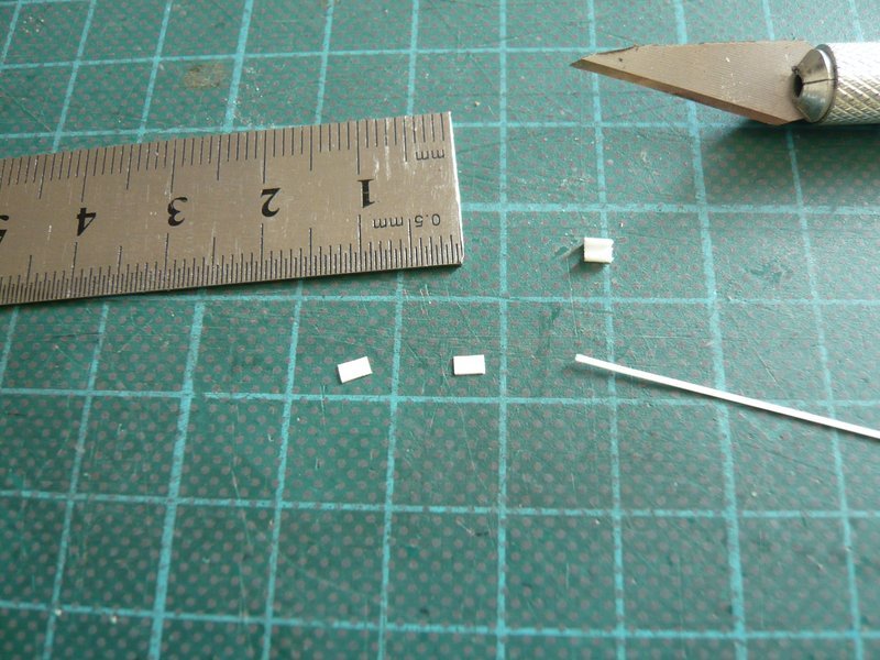
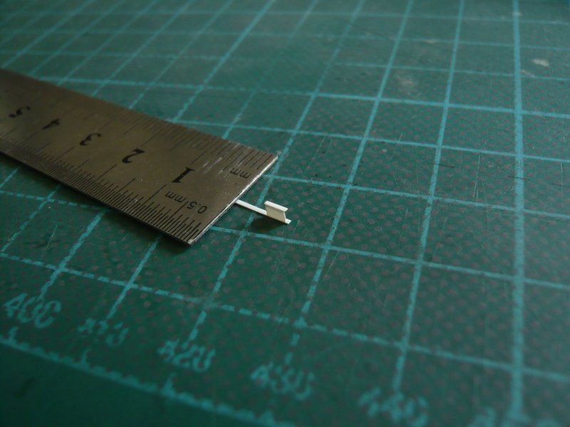
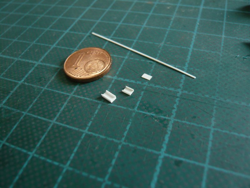
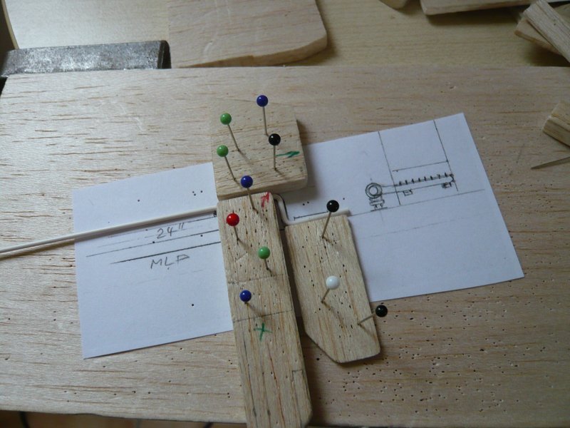
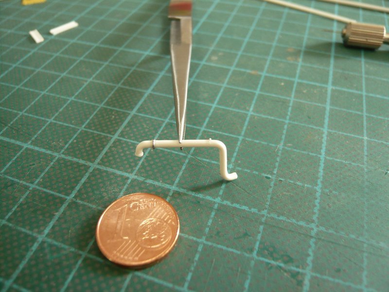
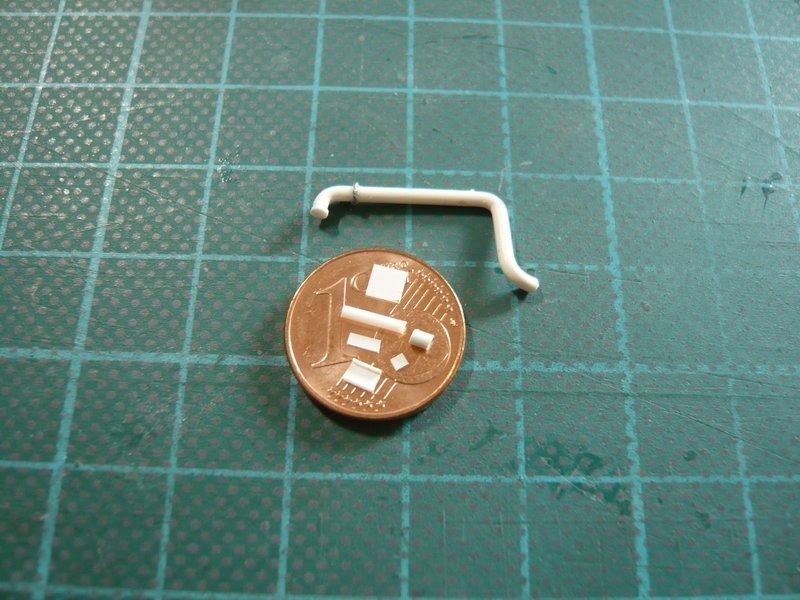
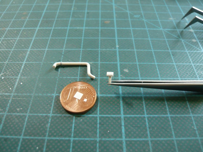
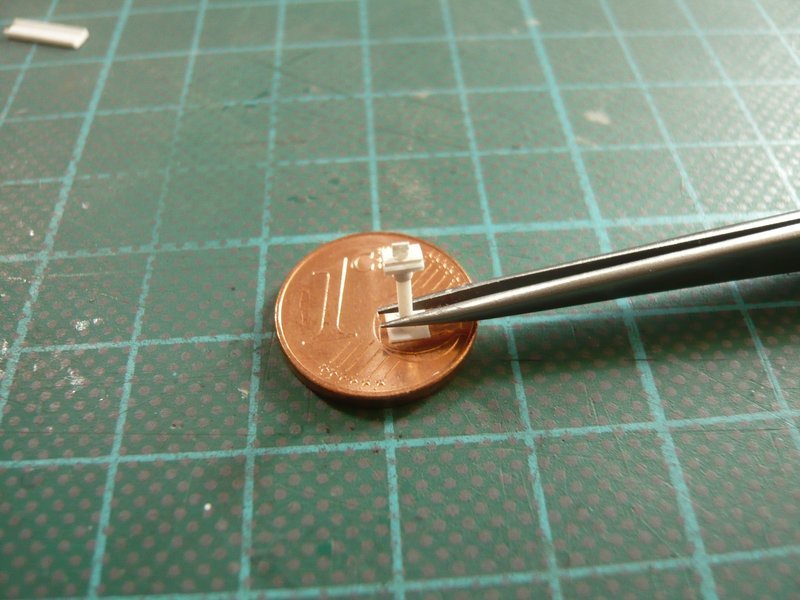
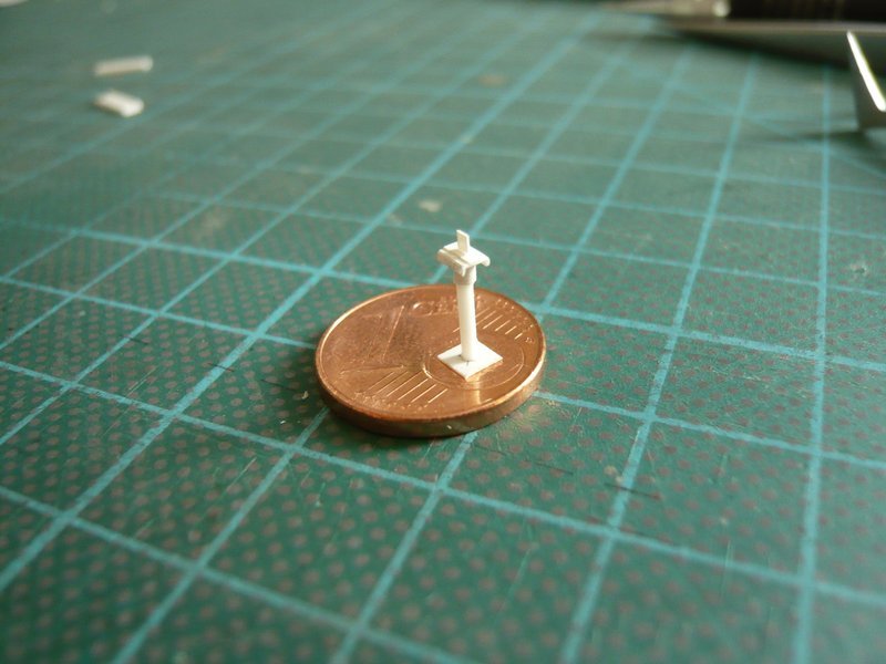
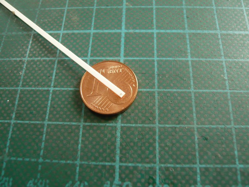
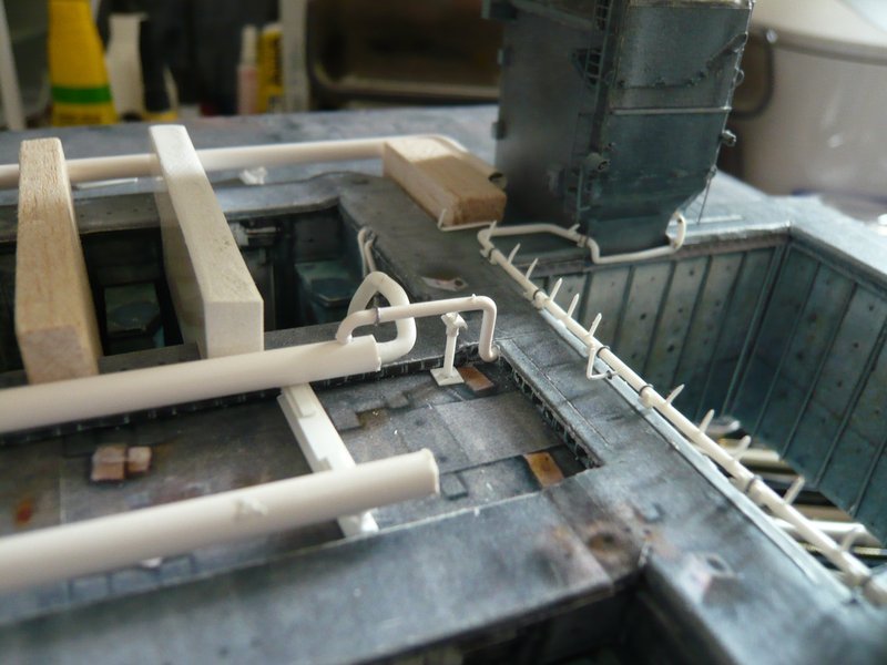
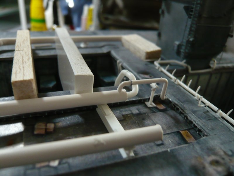
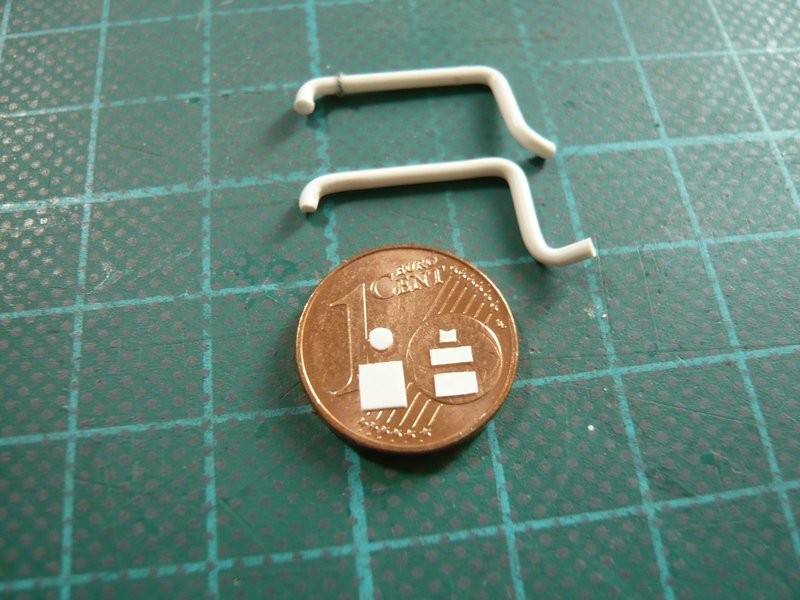
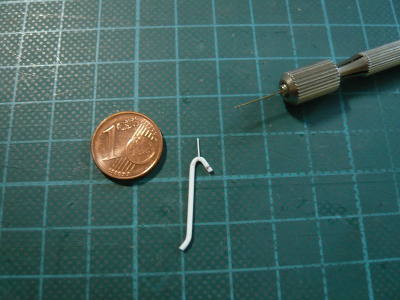
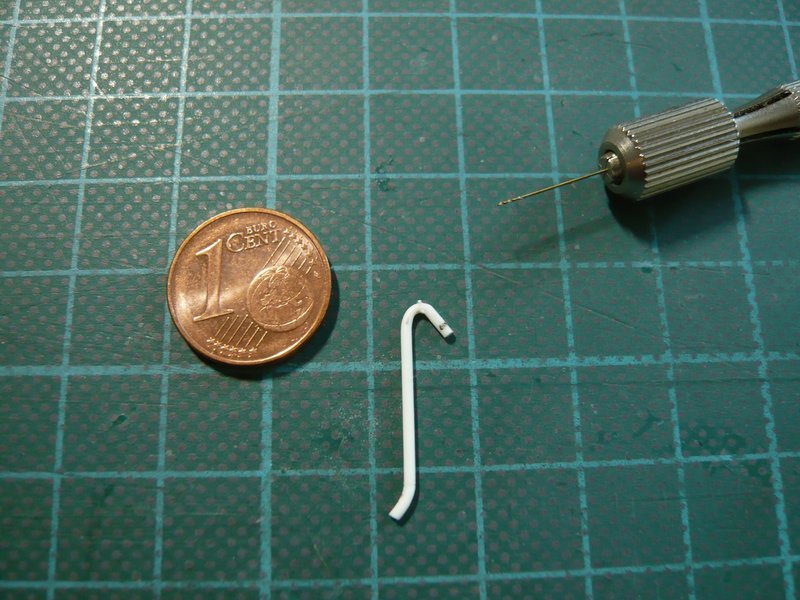
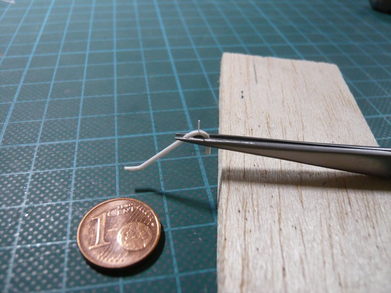
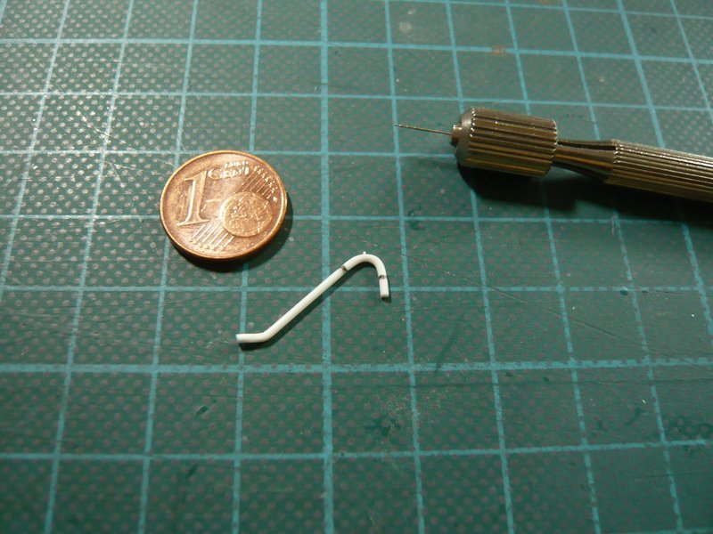
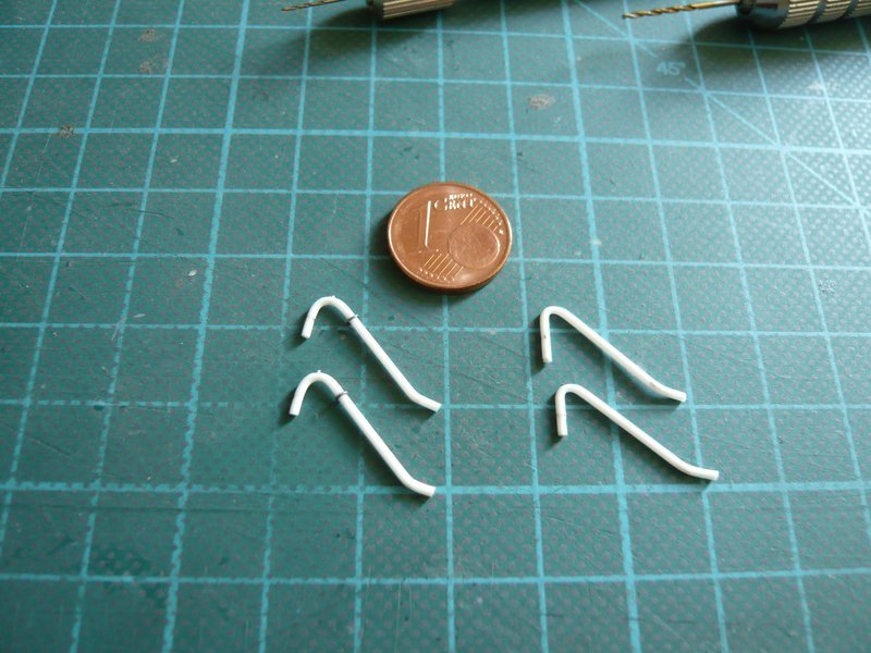
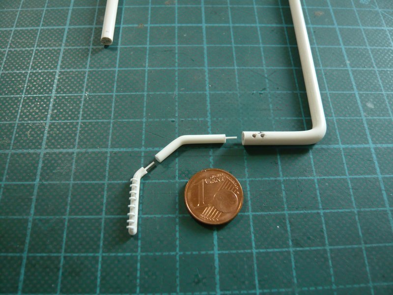
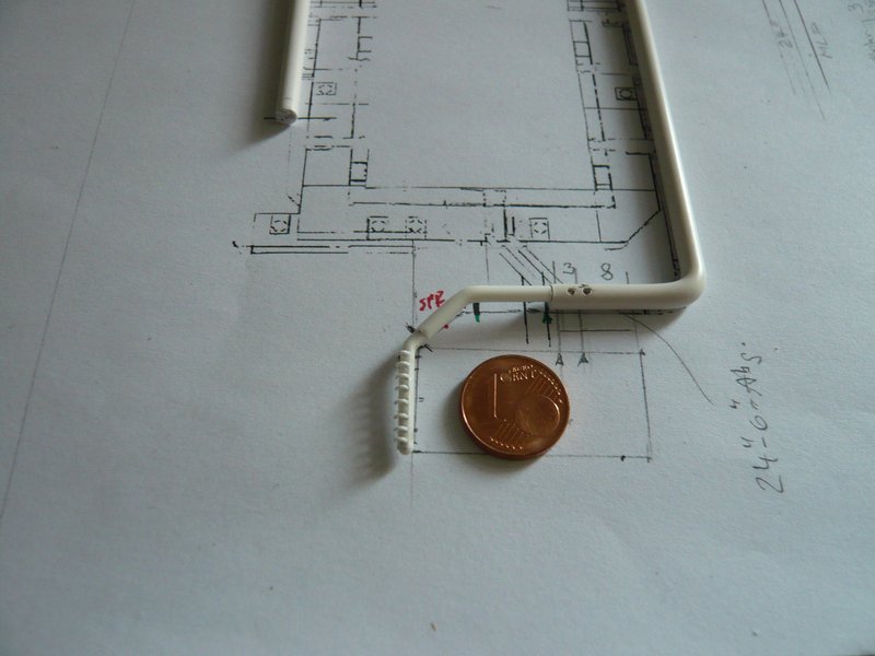
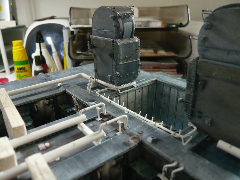
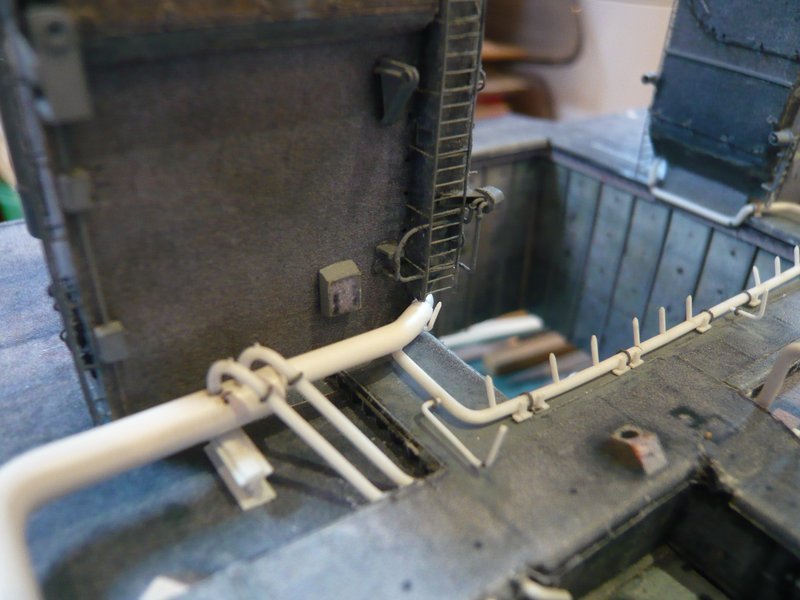
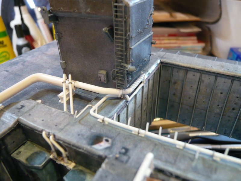
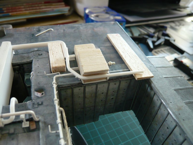
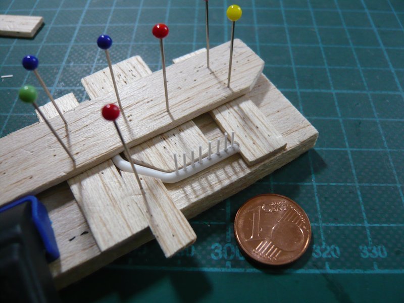
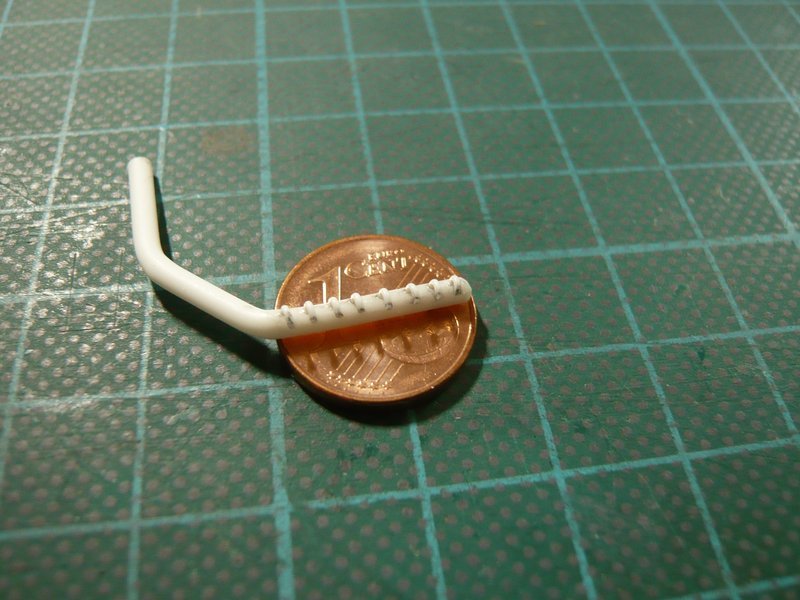
In order to adapt this outlet I initially have bent for simplicity a continuous piece of rod Ø 2,0 mm, ranging from the ring line to the end of the nozzle tube under the TSM, which is sitting on two support angles. This way possibly necessary corrections of position and mounting of the nozzles should be made easier, and only when everything matches this nozzle tube is cut at the last rejuvenation and connected to an intermediate piece with Ø 2,5 mm, which begins at the ring line (Ø 4,0 mm).

Here this continuous pipe is bent, which begins at the ring line.

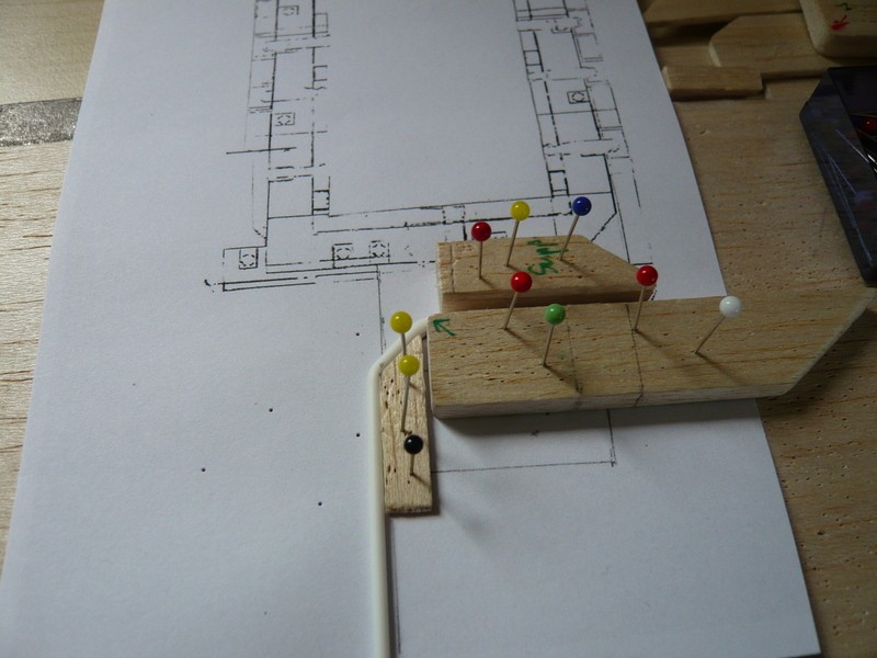
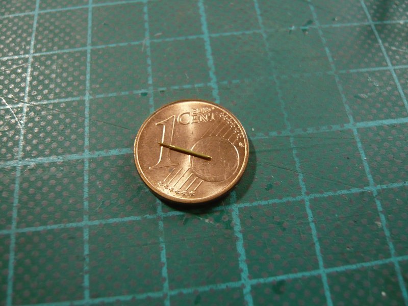
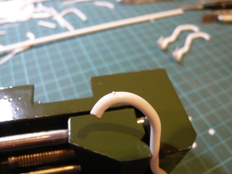
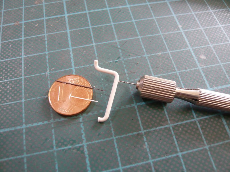
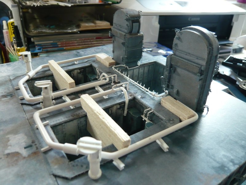
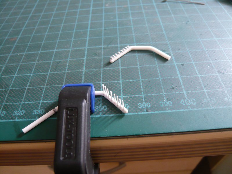
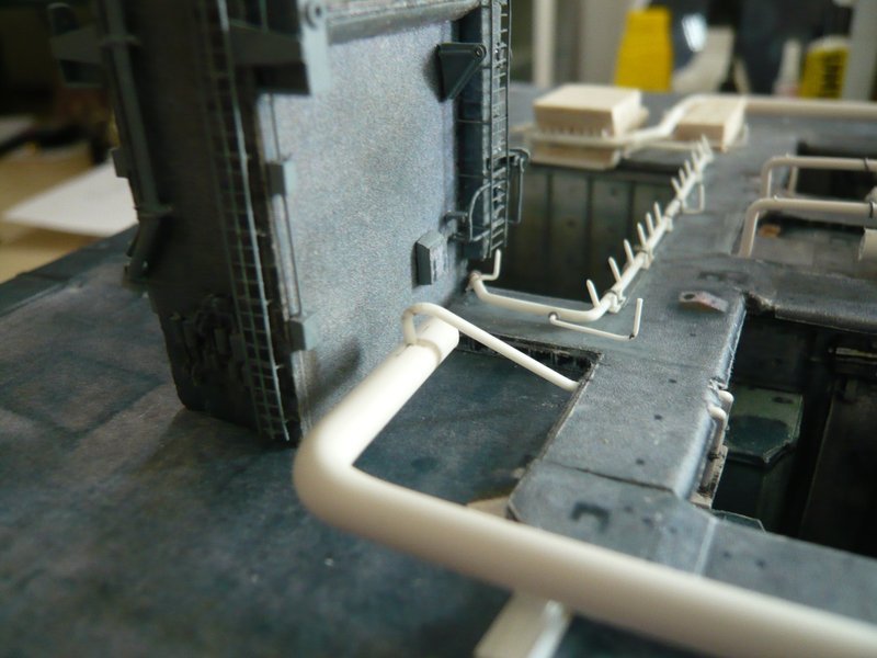
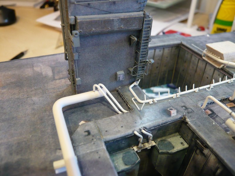
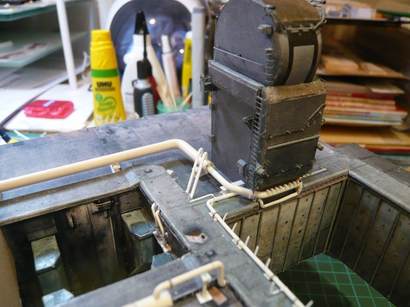
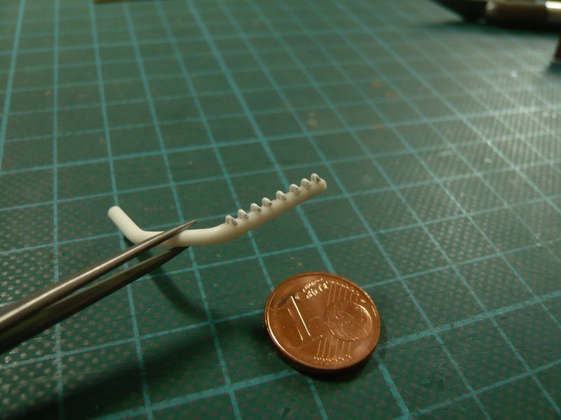
And this is the first test that looks already times quite good,

although the tube seems to be a little too close to the TSM corner,

what I’ll be watching in more detail once more.

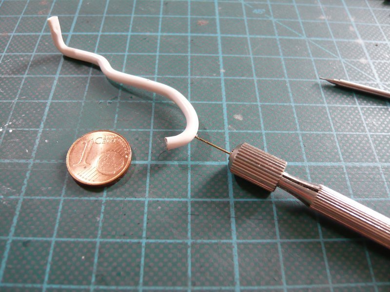
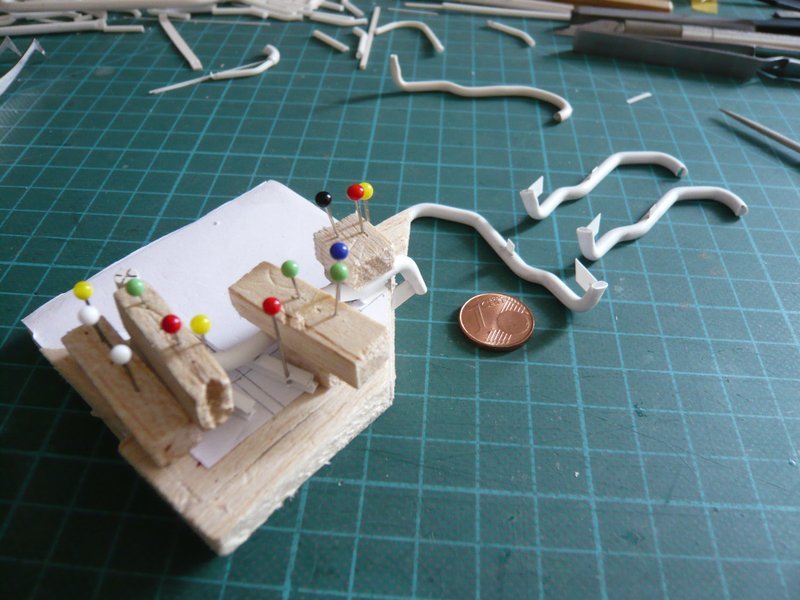
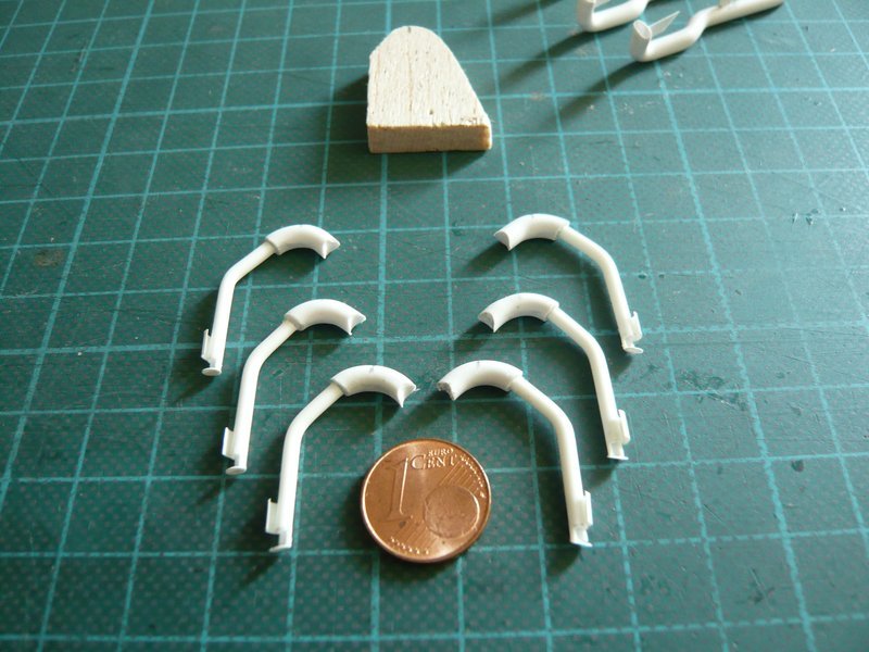
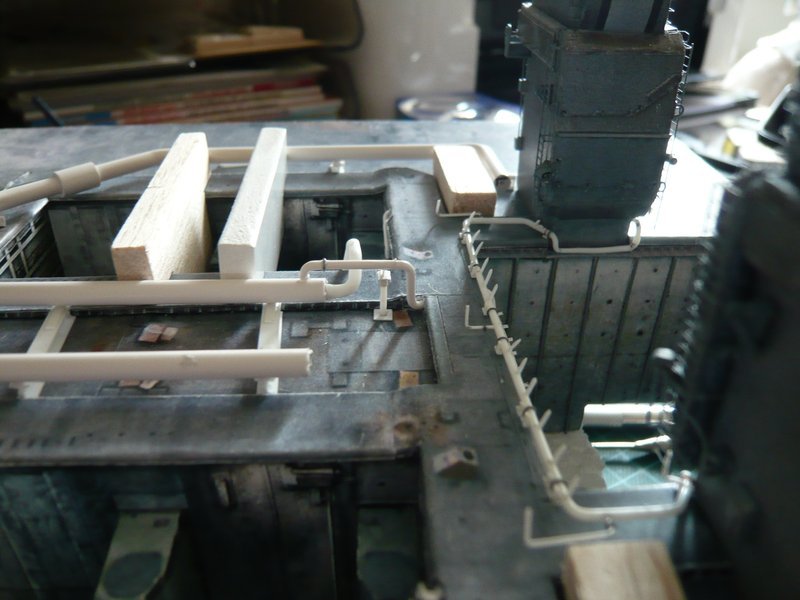
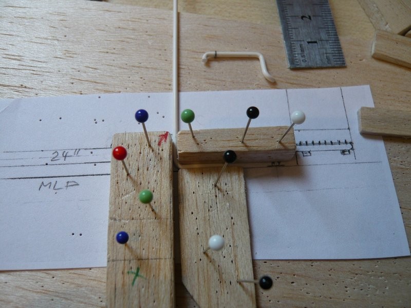
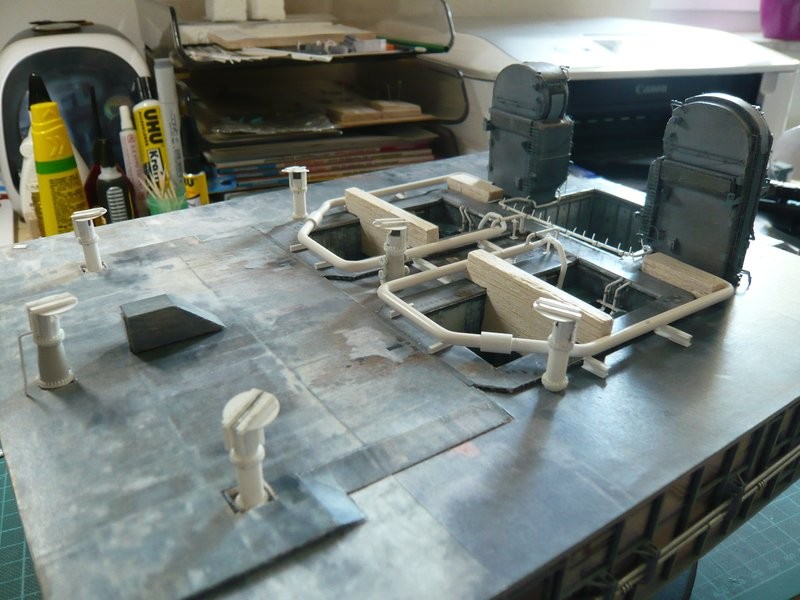
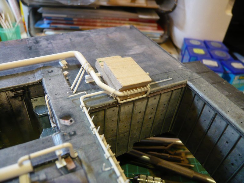
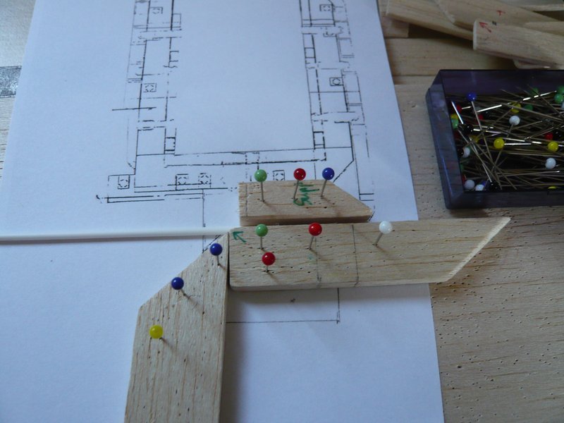
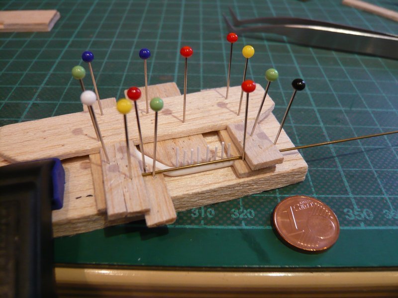
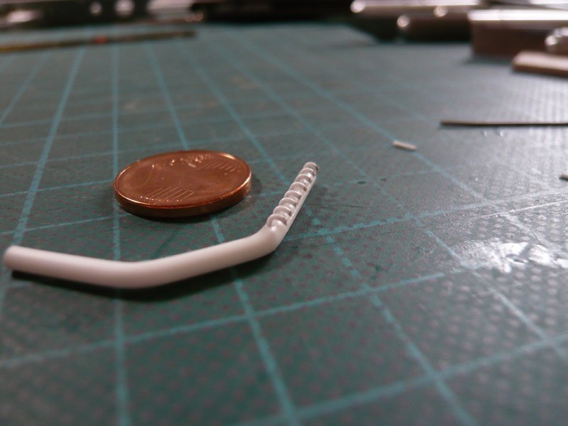
meanwhile shape and seat of the nozzle pipe have been slightly modified, and for facilitating the tests I have tinkered a little TSM Balsa dummy to avoid unnecessary stress for the final TSM.

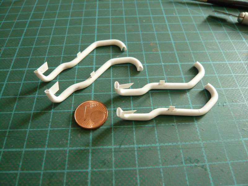
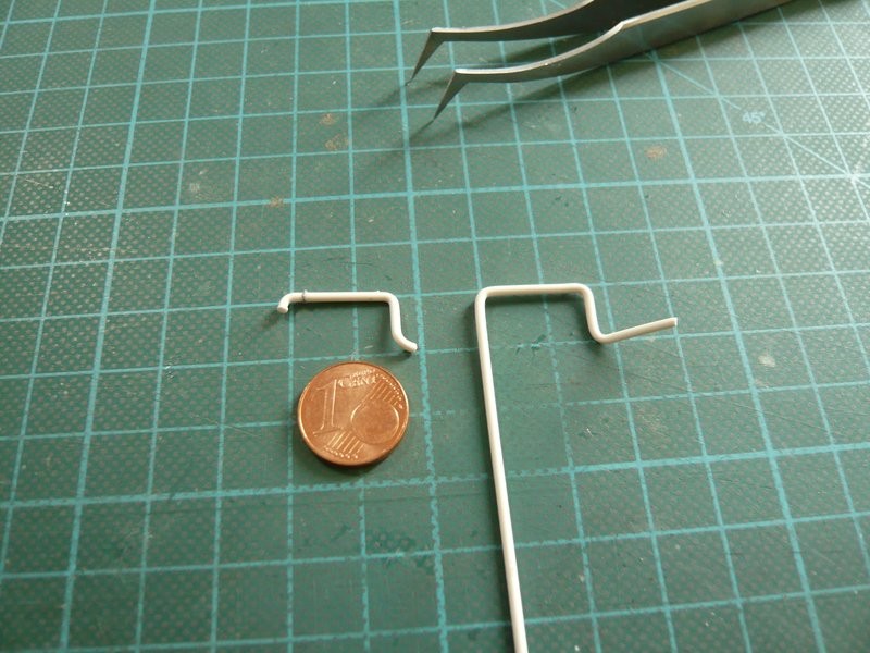
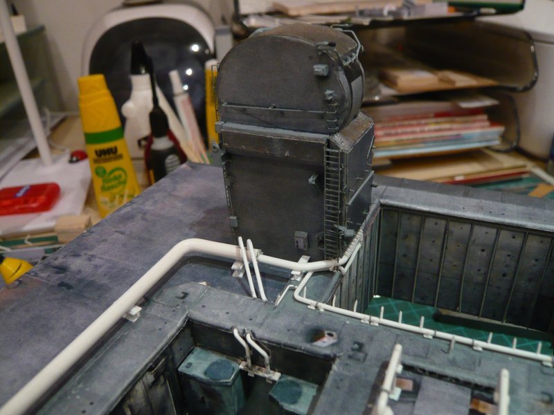
And hence to the tricky nozzles that had already made some headache a year ago dealing with the nozzle pipe on the rear wall of the SSME chamber.

Because my former manufacturing method of the individual nozzles in retrospect appeared as being too complicated, I have fiddled about another solution that should be less stressful.

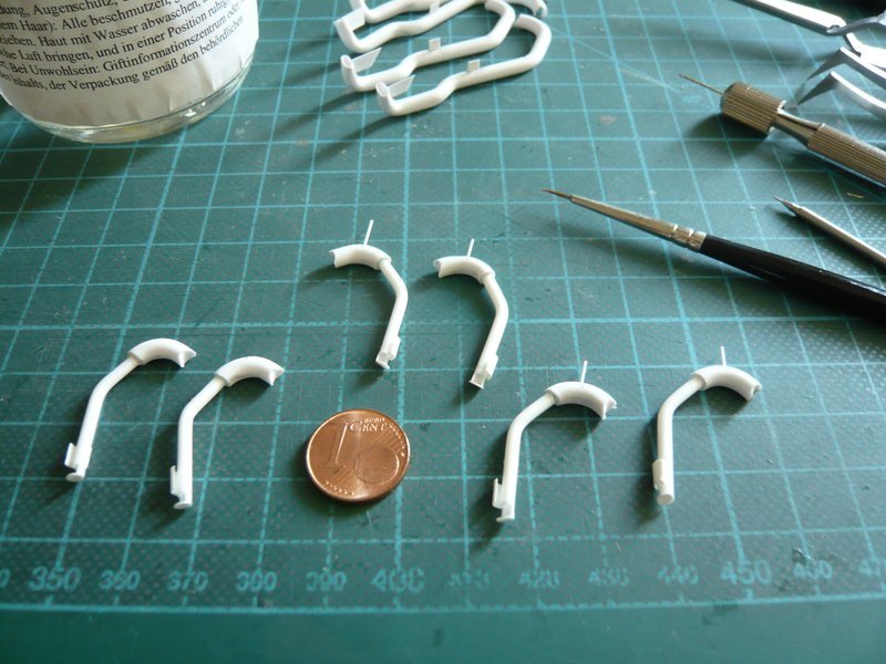
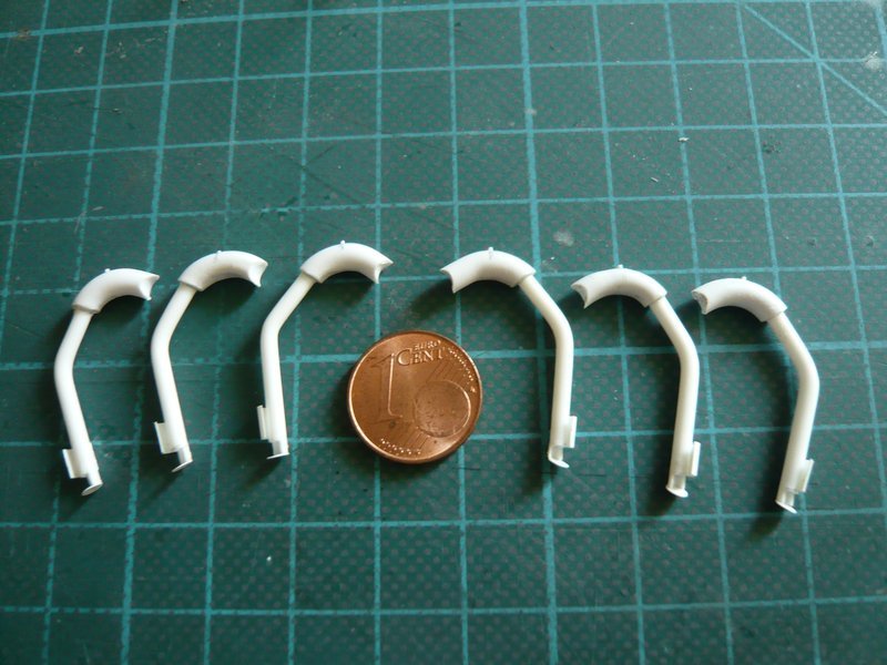
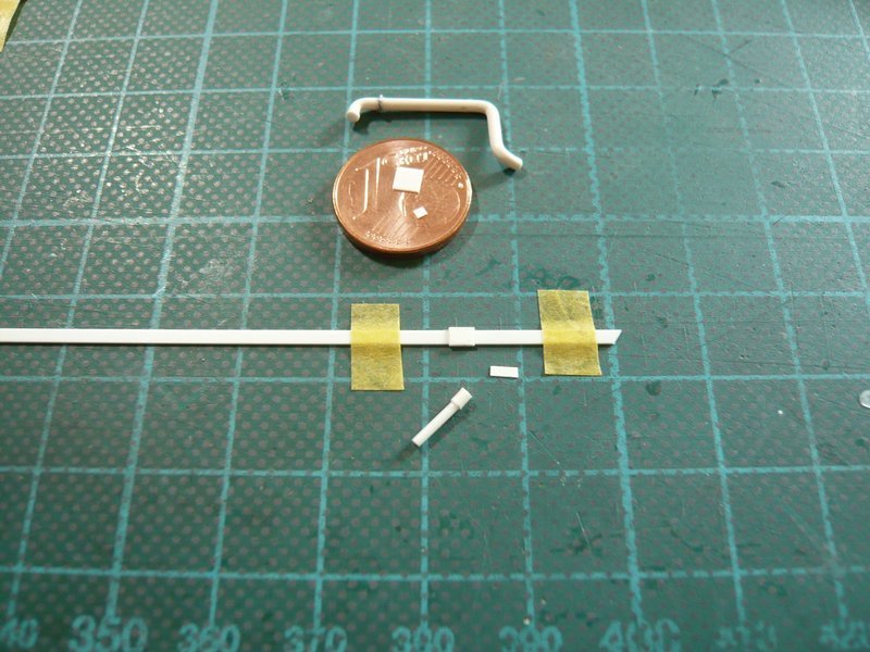
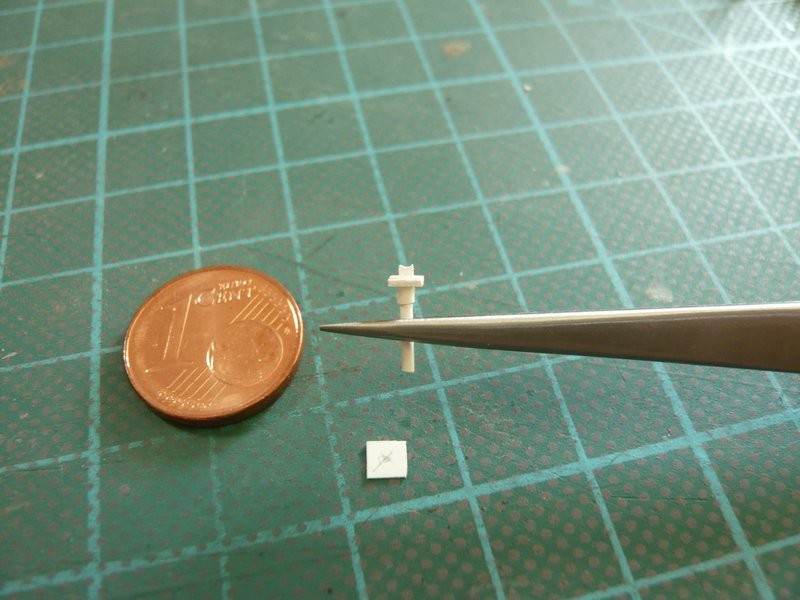
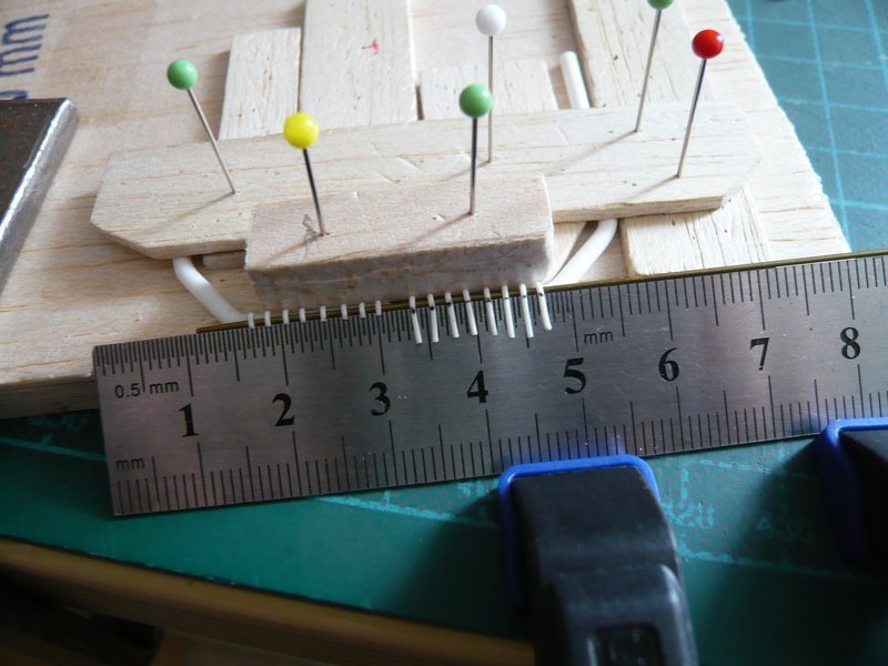
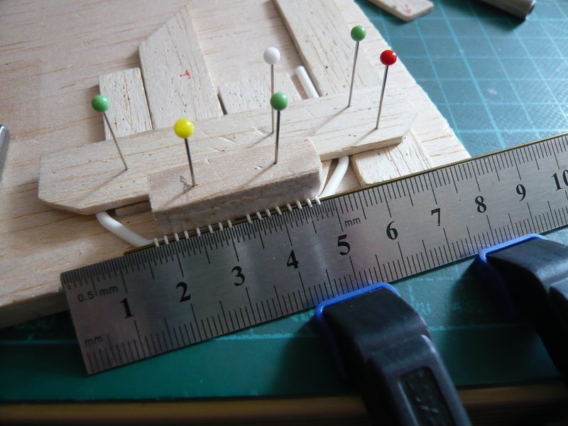
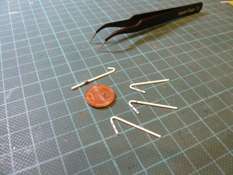
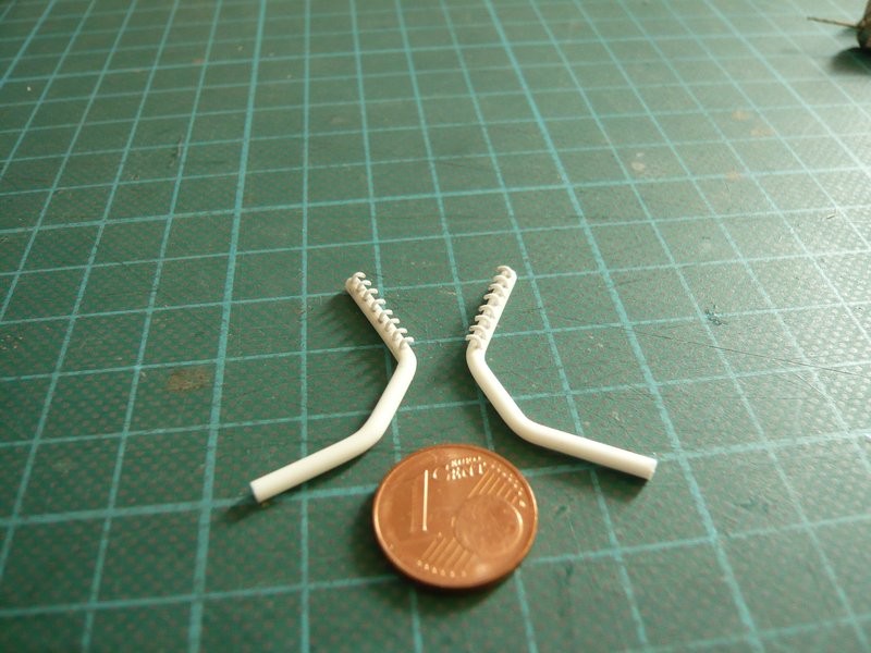
While on the former almost twice as long tube (approx. 32 mm) were arranged six nozzles, on this tube (about 16 mm) under the TSM this time even eight nozzles with Ø 0,5 mm are to be accommodated, resulting in distances of about 1,4 mm.

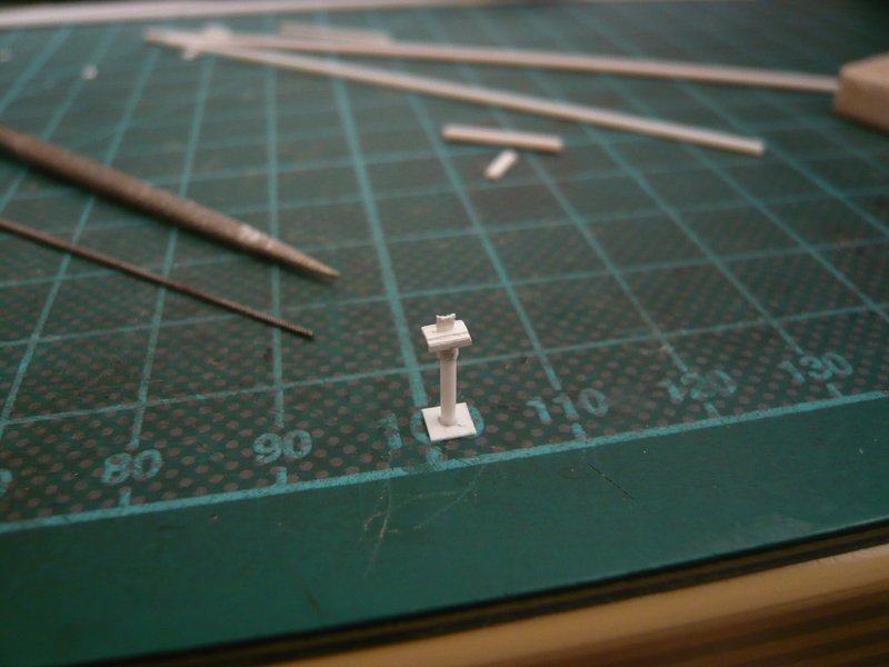
For the marking and drilling I have benefited of a PE template (cmkkits.com) for 0,8 mm rivets, which was very helpful.

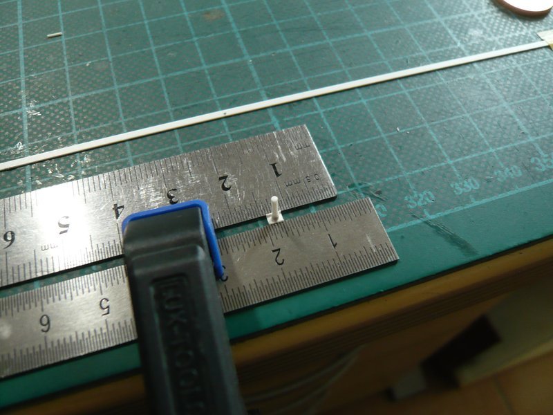
First I have pre-drilled with Ø 0,3 mm and then after that with Ø 0,5 mm.

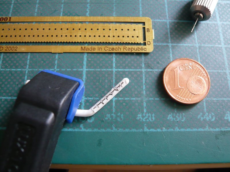
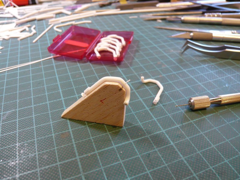
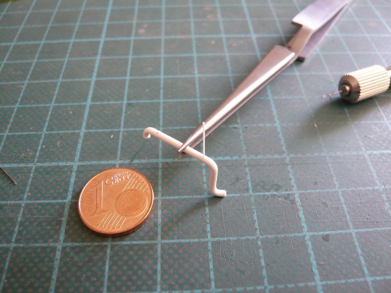
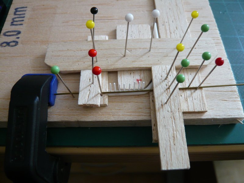
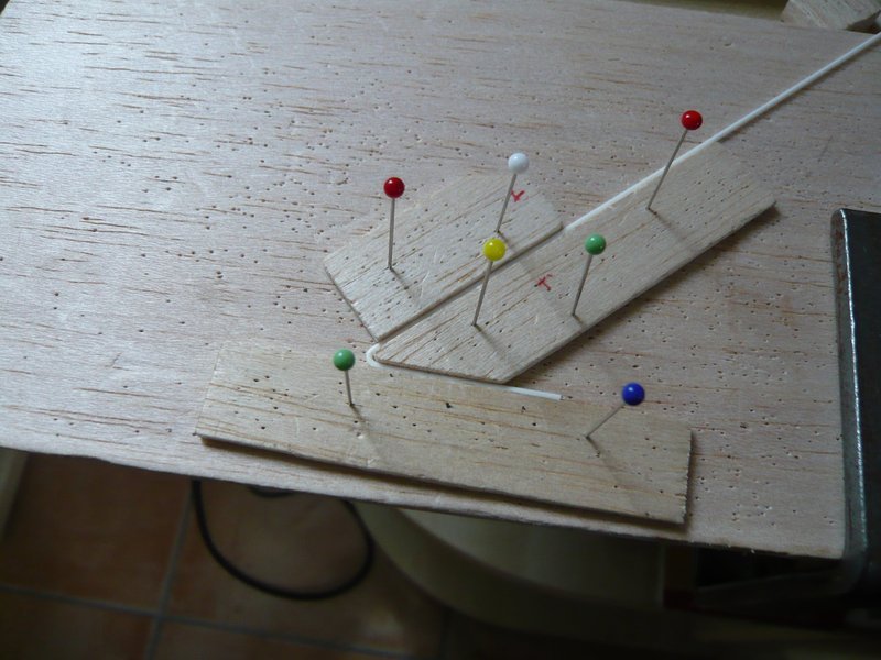
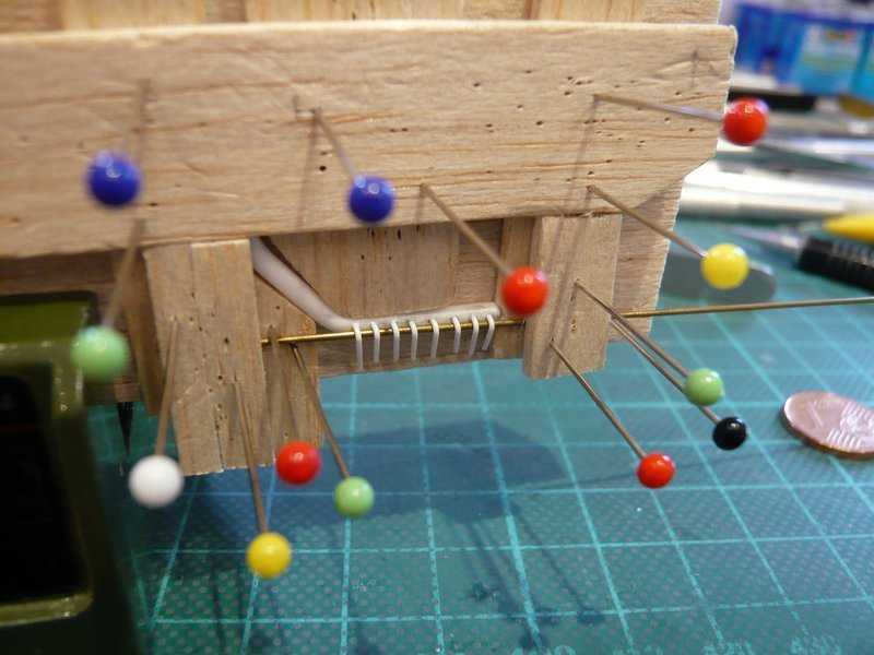
The idea was to insert somewhat longer rods (about 7 mm, Ø 0,5 mm) into the holes, to glue them with MEK and thereafter to bend all together at one time under moderate hot air in the final form, and then to cut.

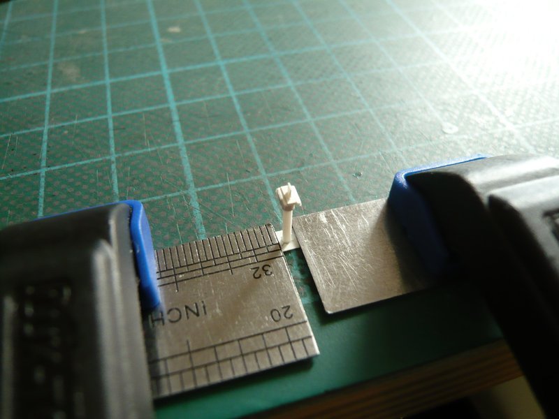
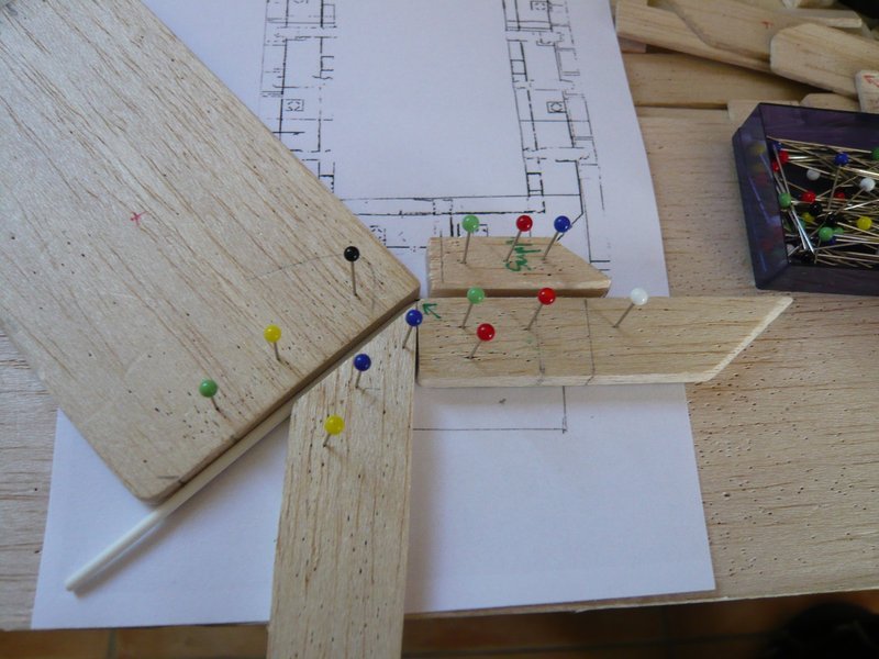
Therefore, the pipe had to be clamped again in a balsa corset, what has proven itself in similar form already several times.

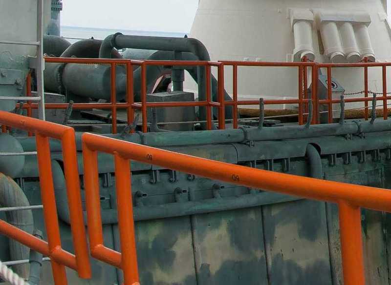
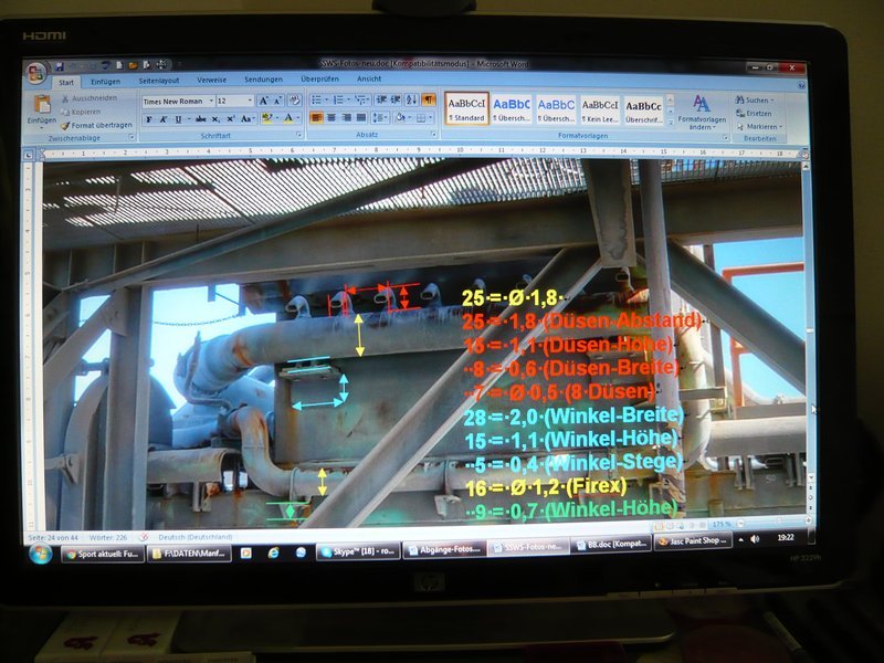
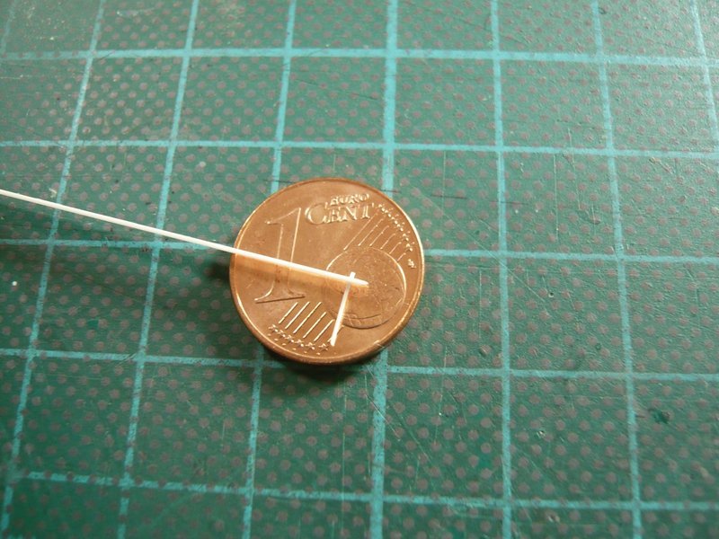
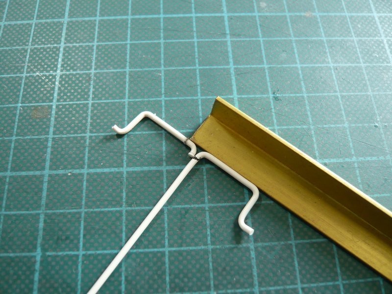
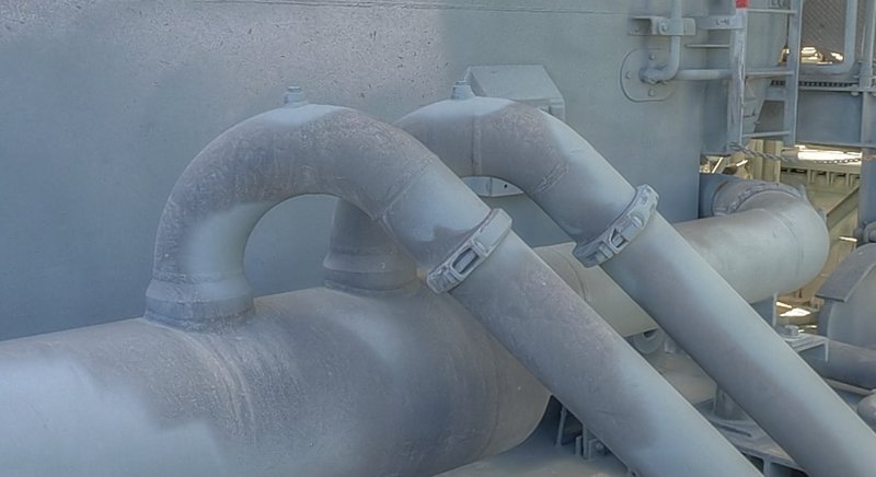
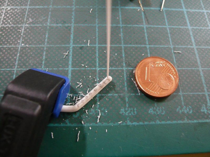
The required clear height of the nozzle bows results from this close-up on the basis of the reference diameter of the nozzle tube (Ø 2,0 mm) to about Ø 0,6 mm,


Source: nasatech.net

which is why I now have clamped a corresponding brass rod with Ø 0,6 mm directly behind the nozzle rods, whereby this Balsa jig looks slowly pretty adventurous.

And now the entire row could be bent, the Proxxon Gun in the right hand, and with Left the rods were carefully bent down with a short Balsa slat,

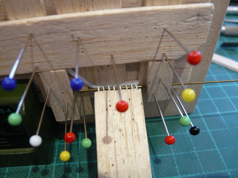
what has worked well straight away.

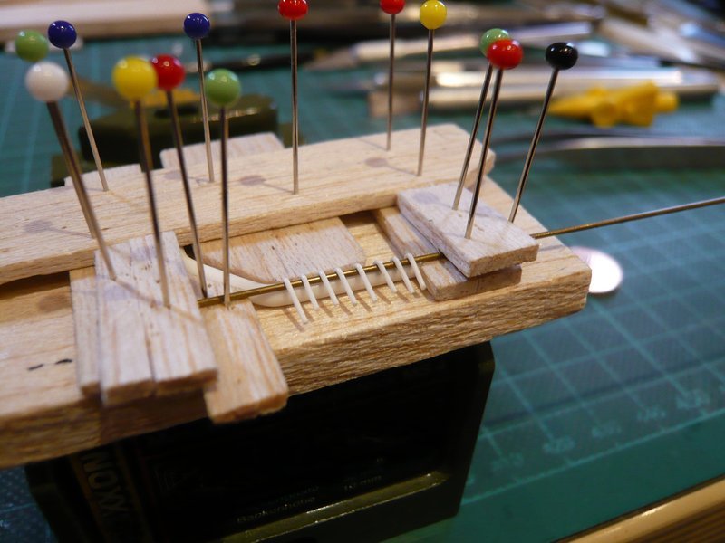
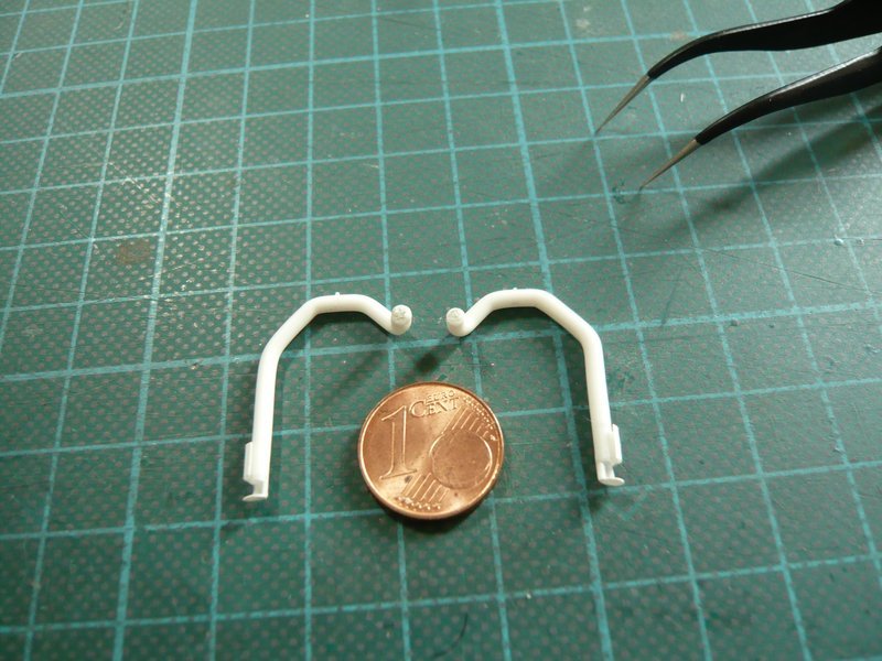
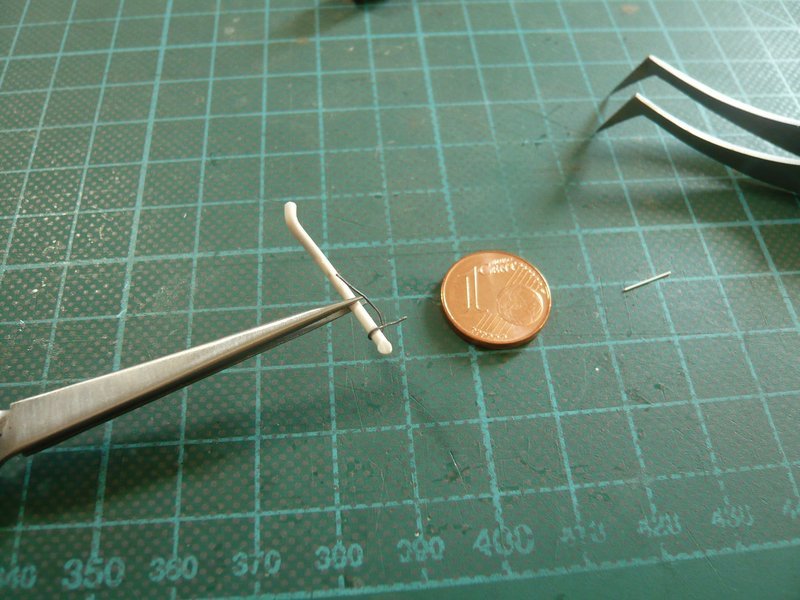
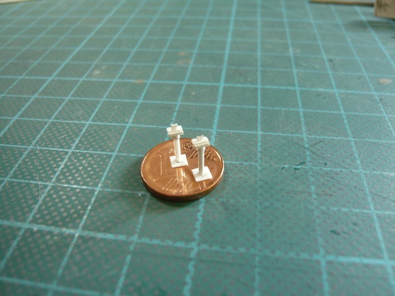
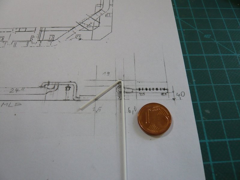
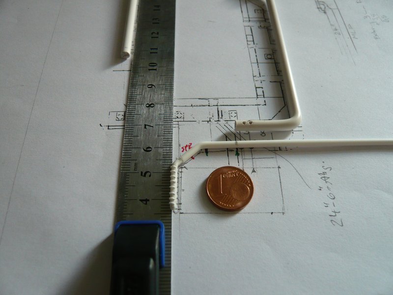
After the nozzle lengths were marked,

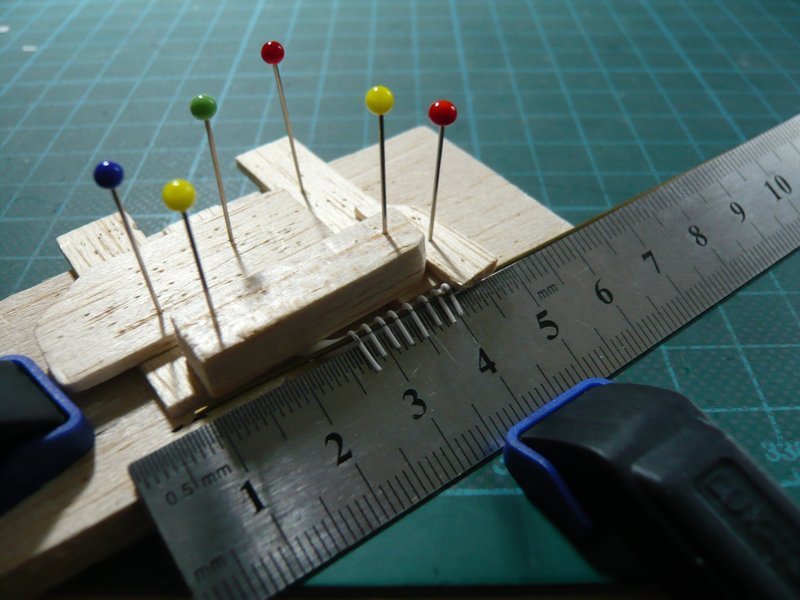
they were cut off on the steel ruler with the cutter chisel.

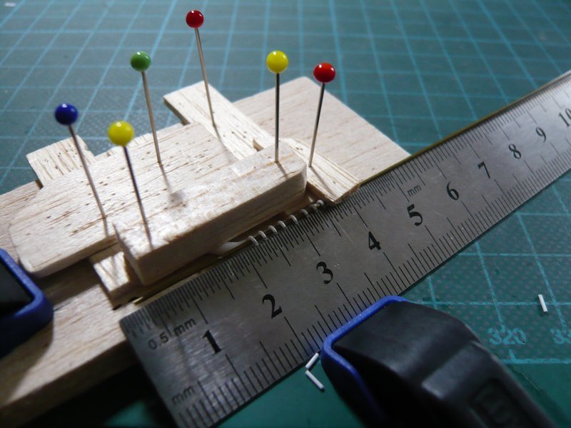
And then it looks like this.

And from this result, I am now totally surprised, because this was not necessarily to be expected.

Now I can calmly turn to the nozzle openings, which can tolerate a little bit tuning.

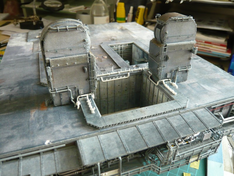
Tomorrow I will test this nozzle pipe on the MLP.

2 Likes

Unbelievable :see_no_evil:

1 Like

Thanks John, as I can see, you’re almost at a loss for words …

Hello friends,

and here are two images of today’s try-on on the MLP.

This is all still pretty shaky, but otherwise fits quite well.

Meanwhile it went on with the other nozzle tube under the LH2 TSM.

At first it was drilled again,

then the 0,5 mm rods for the nozzles were inserted and glued with MEK.

Then again followed my standard clamp procedure, meanwhile patented, for the bending process with inlaid brass rod.

The bending was followed by the reduction of the overhangs, wherefore the already finished nozzle tube was very helpful for measurements and therefore was clamped next to it.

Then the overhangs were separated on the steel ruler.

And these are the two nozzle tubes, left for the LOX TSM and right the new for the LH2 TSM, except for the mirroring almost identical twins.

And so it went on the fly to the 6’’ outlets which run behind the two TSM’s from the ring line, then under the SRB Blast Shields,


Source: nasatech.net

and end on the back walls of the SRB chambers.


Source: nasatech.net]

After the required dimensions were determined, then followed the bending of the rods (Ø 1,0 mm) around a corresponding template, which is by now becomes routine.

Now the appropriate length of the inclined portion only had to be found which one can measure unfortunately nowhere directly due to the oblique arrangement, not even from my little sketch of the true to scale side view.

So only remained Trial & Error with slightly oversize, what then looks so.

Although the bow is is indeed a little too wide and should become a bit narrower,

but from the arrangement it fits already quite well.

And the test fitting of the new nozzle tube right in the picture around the TSM Dummy is also okay.

That’s it for today, tomorrow is another day.

1 Like

Hello everybody,

today also the second 6’’ outlet of the couple has been added, and the other two outlets for the right side I have also still bent. For the clamping rings I have wrapped lead wire Ø 0,3 mm around a 1 mm rod and then cut with a razor blade.

And even on these thin pipes there are the already known nipples, for which I will use Styrene rods with approx. Ø 0,2 mm.

3D-rotatable view of this area at nasatech

Source: nasatech.net

And here the pipes have been “welded” to the ring line and threaded under the Blast Shield.

This fits in so far as quite well into the picture,

now I have to fit in only the correct adapter pipe with the rejuvenation on 12’’ (Ø 2,5 mm) at the end of the 24’’ ring line (Ø 4,0 mm) and to cut the nozzle tube (Ø 2,0 mm) just behind the TSM corner, then the strand is finally complete.

3D-rotatable view of this area at nasatech

Source: nasatech.net

And how could it be otherwise, these rejuvenations stand on a short support, which is constructed similar to the two pillars under the 9’’ transitions at the other end of the ring lines, and therefore they are also on the to-do list.

But before I want to show you still on the fly my announced attempt with the nipple on the prototype of the 6’’ outlet (Ø 1 mm).

The tiny hole on the bend I have pre-drilled with my smallest drill with Ø 0,2 mm. And then I have been amazed, as I have found in my remeasuring of the 0,3 mm rods that they are a little undersized, approx. Ø 0,25 mm, and accordingly might fit well.

After the little rod was glued with MEK and shortened, the outlet with the tiny nipple looks like this.

And so also this detail on the thinnest outlet has been mastered, especially as the clamping rings are far less problematic.

But hold on guys, do you notice anything?

1 Like

Hello everybody,

it’s just a small mistake, but nobody has noticed it, no problem.

Only upon closer inspection of the image I have noticed two things in retrospect which require correction.

Firstly, one can clearly see that the orientation of the nipple (red) does not match with the intended installation position of the outlet on the 24’’ ring line (green), what has to be initially escaped me out of overeagerness.

And on the other hand can be recognized from this photo that the bow is rounded rather like a crooked stick and has a larger opening angle than the previous. Accordingly, the rounding starts directly above the connection point on the ring line and not only after the vertical ascent like at my prototype.

3D-rotatable view of this area at nasatech

Source: nasatech.net

Since that is not so good visible in some photos due to the perspective distortion, I have twisted the following image as long as until the best direct view of the two outlets has revealed, which is similar to the previous image.


Source: NASA

Therefore, new outlets were needed with greater rounding, on their highest points the nipples were inserted,

what looks much better, why I’m satisfied now.

Here once more the comparison of the outlets, whereas the two new outlets (left) have their clamping rings already.

And now to the next step, the adaptation of the nozzle tube (Ø 2,0 mm) to the ring line (Ø 4,0 mm).

For this purpose, the tube was separated after the bend at the TSM corner because there the connecting piece to the ring line starts, which was bent from a rod (Ø 2,5 mm).

To align the course of the parts better before the final bonding, I have drilled the parts with Ø 0,5 mm and then inserted appropriate connection rods.

This allows plug together the strand, whereby the test-fitting on the MLP is facilitated and any necessary length corrections are possible.

And only when everything fits, the parts are then glued together.

1 Like

Hello everybody,

yeah, my solution with the plugged-together-strand has actually paid for itself well.

And this strand I’ve tried on on the MLP, initially with the TSM Dummy, because this is much simpler than with the unhandy real TSM. And lo and behold, a slight shortening of the intermediate piece (Ø 2,5 mm) was necessary actually,

so that the nozzle tube just so fits around the TSM corner and does not protrude too far.

But the acid test came then with the real TSM, and as I had feared, it was really quite closely at the corner,

as one can see here,

across the Firex line and below the ladder through, and left past on the angled nozzle.

Good that it was not tighter, but fortunately it has worked well.

1 Like